
Abstract
Continued research into thermal barrier coatings (TBCs) for internal combustion engines has generated insights into the design of TBCs that can increase fuel conversion efficiency. In this work, two low thermal inertia TBCs (a commercially available Gen 1 material, Gadolinium Zirconate, and a proprietary Gen 2 material) were experimentally tested in gasoline compression ignition (GCI) on a light-duty single cylinder research engine. Compared to a metal baseline, a 250-micron thick Gen 1 coated piston produced an efficiency benefit of 0.4 percentage points (pp) at 6 and 10 bar net indicated mean effective pressure (IMEPn) and a 0.2 pp penalty at 15 bar IMEPn. The Gen 1 coating also showed an uHC and smoke penalty. An 80-micron thick Gen 2 coated piston showed an efficiency benefit of 0.9 pp at 6 bar IMEPn and 0.4 pp at 10 bar IMEPn, but an efficiency penalty of 0.5 pp at 15 bar IMEPn. The Gen 2 coating, which has a lower thermal inertia than the Gen 1 coating, displayed durability problems while the Gen 1 coating did not. A third piston was coated with a 120-micron thick Gen 2 coating everywhere except the high failure outer bowl region, which was coated with a 120-micron Gen 1 coating. This hybrid coating displayed good durability, an uHC emission penalty, a smoke benefit, an efficiency benefit of 0.1 pp at 6 bar IMEPn, an efficiency benefit of 0.4 pp at 10 bar IMEPn, and no change in efficiency at 15 bar IMEPn. These results indicate that a durable Gen 1/Gen 2 coating can provide an efficiency benefit to GCI combustion, and that further improvements on piston-spray interaction optimization and surface sealing of the TBC, as well as increasing the coated combustion chamber surface area (e.g. head and valves) can add further improve efficiency.
Introduction
Diesel is the primary fuel for compression ignition engines around the world. While this has been true for decades, increasingly stringent greenhouse gas emissions and criteria pollutant regulations are pointing toward a future where diesel will be displaced by a myriad of fuels. Many such fuels are currently not available at the pump in most parts of the world. As trends in electrification continue to displace light-duty gasoline engines with hybrid electric or battery electric vehicles, the demand for gasoline is expected to decrease. This creates a unique opportunity where gasoline, a widely available fuel, could replace diesel in compression ignition, serving as a steppingstone toward decarbonization of the transportation sector.
Diesel is an amalgam of heavy hydrocarbons that result in a fuel with low volatility, high sooting potential, and high chemical reactivity. Because of its high reactivity and low volatility, diesel combustion is mixing controlled, with fuel injected near top dead center (TDC). This results in a diffusion burn, where a fuel-rich plume mixes with air at the periphery of a standing flame. The fuel-rich region of the flame produces particulate matter and soot while the near-stoichiometric periphery of the flame produces thermal NOx. 1 Both of these criteria pollutants require complex aftertreatment systems to meet current regulations, and future projected regulations are trending toward near-impossible-to-meet tailpipe standards for diesel engines. The addition of exhaust gas recirculation (EGR) is an effective NOx mitigator, but results in a soot penalty, creating the so-called soot-NOx tradeoff that limits the cleanliness of engine-out diesel exhaust.
There are many advantages and challenges associated with replacing diesel with a fuel like gasoline. As an amalgam of lighter hydrocarbons, gasoline is significantly more volatile than diesel. Gasoline has a lower sooting potential than diesel and can tolerate higher levels of EGR. While gasoline cannot completely break the soot-NOx tradeoff like short-chain oxygenated fuels (e.g. methanol, 2 ethanol, 3 or di-methyl ether 4 ), it can lessen the severity of the soot-NOx tradeoff, thereby lowering engine-out criteria pollutants. 5 With lower engine-out criteria pollutants, other changes can be made to the operating strategies to increase efficiency to higher-than-diesel levels.
Gasoline is also significantly less reactive than diesel. This, combined with its high volatility, enables not only mixing controlled compression ignition strategies, but also kinetically-controlled compression ignition strategies. Kinetically-controlled compression ignition is an umbrella term for compression ignition combustion strategies that are premixed or partially premixed – the key is that kinetically-controlled combustion is not mixing-limited and thus the heat release process is dictated by the compositional and temperature stratification in the cylinder at the start of combustion.6,7 With a significantly lower degree of stratification than mixing controlled combustion, kinetically-controlled combustion results in lower thermal NOx and particulate matter emissions. However, emissions of CO and unburned hydrocarbons (uHC) are higher due to premixed fuel in the crevices and near-wall regions that never reach a high enough temperature to complete oxidation. 6
Kinetically-controlled combustion is generally more difficult to control than mixing controlled combustion. For any fuel in mixing controlled combustion, the heat release process is controlled by injection timing, duration, and pressure. In premixed kinetically-controlled combustion, the combustion process is generally more separated in time from the injection process, making the cylinder-to-cylinder control mechanism over the heat release process less obvious. With gasoline, partially premixed compression ignition obtains a control mechanism: fuel stratification. Strategies like partial fuel stratification (PFS) 8 demonstrate that fuel stratification can be employed to control the heat release process of kinetically controlled combustion, but that the robustness of control is a strong function of the operating condition and fuel chemistry. 9
While mixing controlled compression ignition provides robustness, there is still the opportunity to take advantage of the superior emissions qualities of kinetically-controlled combustion with gasoline. A gasoline compression ignition (GCI) strategy that combines both mixing and kinetically-controlled phases, called partially premixed compression ignition (PPCI)-diffusion in recent work,5,10 demonstrated robust control while showing an increase in efficiency and a decrease in engine-out soot and NOx.
In parallel with developing new combustion strategies for alternative fuels in compression ignition, the addition of technologies that can improve fuel conversion efficiency in internal combustion engines is of significant research interest. One such technology is thermal barrier coatings (TBCs). Research into TBCs for internal combustion engines has a rich history over the last few decades, with many conflicting results. The idea that a low thermal conductivity ceramic will result in elevated surface temperatures is undisputed, but whether this translates into a fuel conversion efficiency benefit is the subject of debate.
A plethora of research is able to provide some key insights into how to design TBCs to elicit the desired efficiency benefit that many have pursued over the last few decades. First, not only should the thermal conductivity be low, but the volumetric heat capacity should be low as well. This results in low thermal inertia coatings that demonstrate a “temperature swing,” where the surface of the TBC increases rapidly in response to combustion to reduce in-cylinder heat transfer during the expansion stroke, and then decreases rapidly during gas exchange to avoid charge heating penalties. 11 Second, the surface roughness of the TBC must be extremely low.12,13 Rough TBC surfaces result in an increase in total surface area, which increases total convective heat transfer, and can have a fuel storage effect, negatively impacting combustion efficiency and increasing engine-out uHC emissions. 14 Third, the porosity of the coating at the surface of the TBC should be minimized. 15 This is a difficult guideline to abide by since increasing porosity is an effective way to reduce the thermal inertia of the coating.16,17 However, at the surface, pores act analogous to surface roughness. Additionally, a porous microstructure accessible by combustion chamber gases can result in compression losses as the high pressure gases diffuse into the coating. This would also result in significant fuel absorption. Using either a natively low porosity material 18 or using a seal coat or a surface densification spray methodology 19 with a natively high porosity material are effective ways to mitigate surface porosity. However, it is important that if one of the latter methods is used, the surface thermal inertia must not be significantly higher than the rest of the TBC or performance of the coating will rapidly degrade.
Regarding the thickness of the coating, there are competing factors. The penetrative depth of a material undergoing a cyclic heat transfer profile, such as a TBC in an internal combustion engine, is a function of the material’s thermophysical properties. 20 Physically, this corresponds to the depth with which the cyclic temperature profile persists. Selecting a TBC whose thickness equals its penetrative depth maximizes the temperature swing. Note that the penetrative depth varies with operating condition. Increasing the thickness of the coating beyond its penetrative thickness increases the average surface temperature of the coating without increasing the magnitude of temperature swing. While this could still be advantageous for reducing heat transfer losses, it also results in charge heating. In spark ignition or compression ignition with diesel, charge heating lowers the volumetric efficiency and increases knock propensity. 21 However, in GCI, where some operating conditions require breathing strategies such as exhaust rebreathe, negative valve overlap, or uncooled external EGR to achieve high intake valve closing temperatures,22,23 charge heating would actually be beneficial. Additionally, elevated surface temperatures from TBCs whose thickness is in excess of their penetrative depth resulted in improved combustion efficiency in homogeneous charge compression ignition (HCCI). 19
The goal of TBCs is to reduce heat transfer losses by reducing the temperature difference between the gas and the wall without impacting any other parameter that affects heat transfer. It was discussed above that surface roughness and open surface porosity should be minimized to ensure that the surface area for heat transfer is not unintentionally increased through the application of a coating. An unsettled debate in the community exists about whether the elevated surface temperature of the TBC impacts the thermal boundary layer and convection heat transfer coefficient. 24 If the elevated surface temperatures allow chemical reactions closer to the combustion chamber surfaces, a convection vive effect may occur, which would raise the convective heat transfer coefficient. Therefore, if this convection vive effect exists and depending on its severity, it is theoretically possible for a smooth, low porosity, low thermal inertia TBC to increase heat transfer. If convection vive is a consideration, it would generally reduce the effectiveness of TBCs and favor thinner coatings.
This work aims to experimentally evaluate the impact of low thermal inertia TBCs on GCI combustion, using state of the art TBCs that were designed from the learnings of previous work. To do so, three pistons are studied at three different GCI operating conditions. One piston is coated with a commercially available low thermal inertia TBC, Gadolinium Zirconate (GZO). A second piston is coated with a proprietary TBC material with a lower thermal inertia than GZO. Finally, a third piston is coated with a combination of the two studied TBCs to increase durability.
Experimental setup and methodology
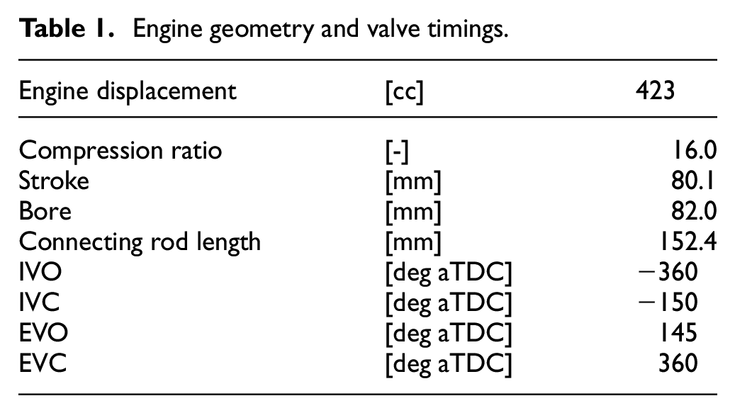
The experiments performed in this work were conducted on a single-cylinder research engine consisting of a 4-cylinder production GM engine head, with one cylinder fully instrumented and mounted to an FEV single cylinder engine block. The remaining three cylinders were deactivated. The piston was a shallow toroidal bowl geometry and the injector included angle was 150°. Details on the engine geometry and valve timing are shown in Table 1.
Engine geometry and valve timings.
A diesel common rail fuel system with a Bosch CP3 pump and a Denso solenoid-style injector was used. Gasoline has a lower lubricity than diesel. Therefore, a lubricity additive (Infineum R655) was blended at a concentration of ∼0.05% by mass. Previous work with ethanol showed that lubricity additive at this concentration did not impact combustion chemistry. 25 Data acquisition and engine control were handled by a custom-built LabVIEW code. Low-speed data acquisition of pressure, temperature, flowrates, and emissions were recorded at 1 Hz. A Horiba MEXA 7100-DEGR measured five-gas emissions in the exhaust and the CO2 concentration in the intake. A Kistler encoder mounted on the crankshaft was used to synchronize crank angle-resolved measurements of cylinder pressure, intake runner pressure, exhaust runner pressure, and common rail fuel pressure with a resolution of 0.1°. A Cambustion DMS 500 was used to collect the particulate size distribution. The filter smoke number (FSN) is calculated using a correlation between FSN and the measured soot concentration in units of mg/m3. 26
At each operating condition, 300 consecutive cycles were recorded under steady-state operation. A custom MATLAB code was used to process the data, including a statistical-based uncertainty analysis. 27 This uncertainty analysis propagates uncertainty with a confidence interval of 95% using the following equation at each step of data processing:
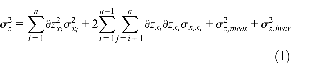
where
The following set of equations define performance parameters used in this work:
The net fuel conversion efficiency (NFCE) is defined as the work output of the cycle divided by the total fuel energy input, given by the following equation:

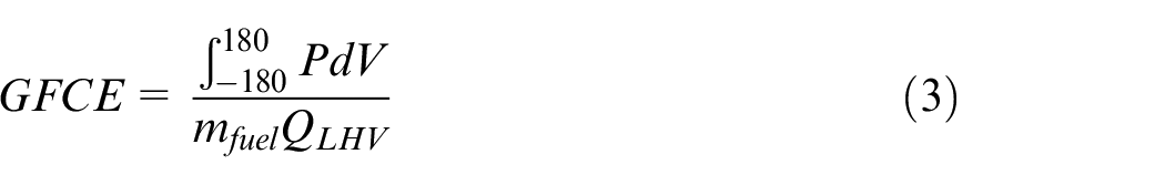
The gross fuel conversion efficiency (GFCE) is defined as the work output of the compression and expansion strokes divided by the total fuel energy input, given by the following equation:
The combustion efficiency is defined as the total fuel heat release divided by the total fuel energy input, calculated using measurements from the emissions analyzers and given by the following equation:

where
The net/gross thermal efficiencies (N/GTE) are defined as the work output of either the total cycle or the compression and expansion strokes, respectively, divided by the total fuel heat release, since the fuel heat release is the energy that is added specifically to the thermodynamic cycle. Therefore, the N/GTE is the N/GFCE divided by the combustion efficiency:

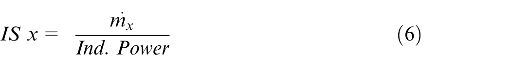
The indicated specific emissions (IS) of a species, x, is defined as the mass flowrate of x in the exhaust divided by indicated power output of the engine:
These definitions can be found in Heywood. 28
Since all of the cases considered are moderately or highly boosted, a turbocharger model is used to determine the back pressure level required to obtain a certain boost level given a target turbocharger efficiency,
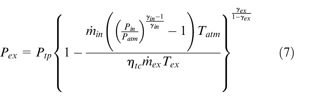
where
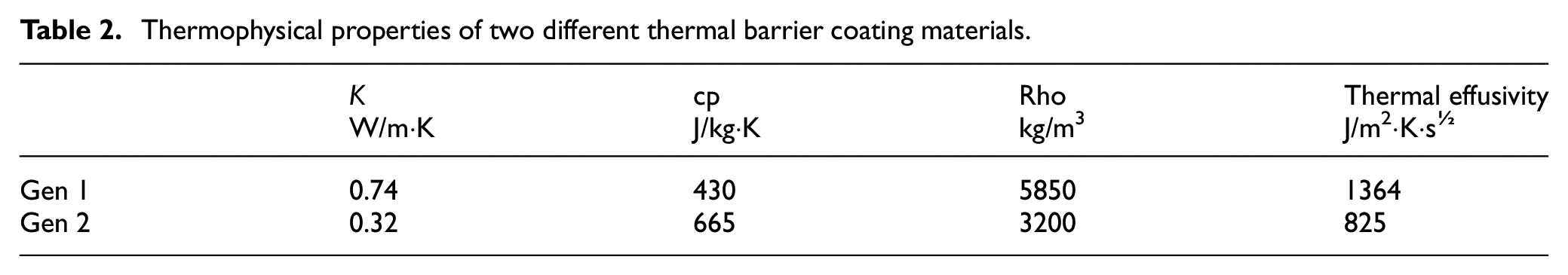
The purpose of this experimental work is to evaluate the impact of TBCs on GCI combustion. The two TBC materials studied, referred to as Gen 1 and Gen 2, have the thermophysical properties shown in Table 2. The Gen 1 coating is a ceramic that is commercially available, Gadolinium Zirconate, with a porosity level of ∼15%. The Gen 2 coating is an advanced proprietary ceramic formulation, with a somewhat higher level of porosity than the Gen 1 coating. All of the coatings in this work were polished to achieve a surface roughness of 2 Ra or lower, which was achievable in all open areas of the piston. In the cusp of the bowl, it was difficult both to polish and to measure the actual roughness. Thus, it is not possible to say with certainty that the surface roughness in the cusp of the bowl was below 2 Ra, it was not excessively high either.
Thermophysical properties of two different thermal barrier coating materials.
Results
Performance of Gen 1 and Gen 2 coated pistons in GCI
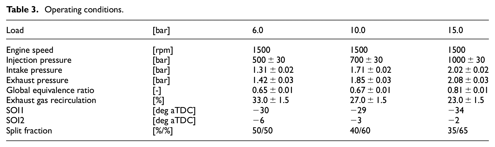
Three GCI operating conditions will be studied in detail in this work, shown in Table 3.
Operating conditions.
Charge heating is a well-documented phenomenon associated with TBCs. This is especially true when the thickness of a TBC is thicker than its penetrative depth. For materials with low thermal inertia like the TBCs studied in this work, the penetrative depth tends to be very small. For the Gen 1 material GZO, the penetrative depth is roughly ∼120 microns at this engine speed. Increasing the TBC thickness beyond the penetrative depth will result in charge heating as the surface temperature does not swing back down to the baseline metal temperature during gas exchange.
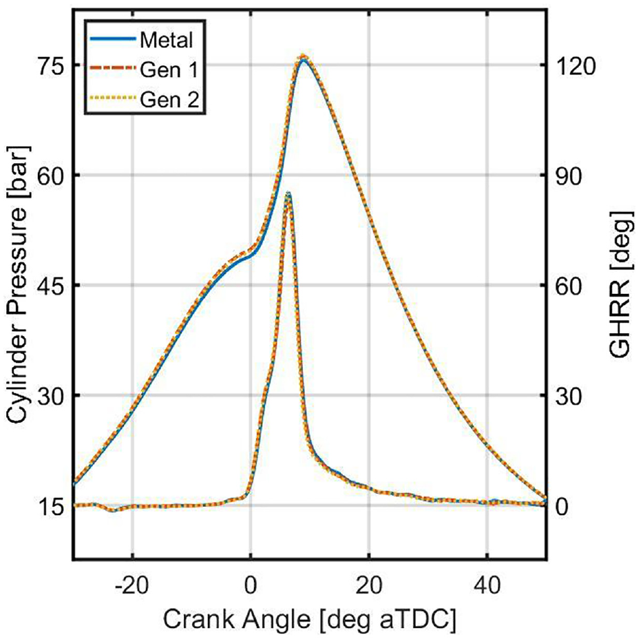
In addition to charge heating, reduced heat transfer during the compression stroke also increases the temperature and pressure during compression, which will advance the start of combustion of the kinetically-controlled PPCI phase. Figure 1 displays the cylinder pressure and the gross heat release rate (GHRR) of the metal baseline and the 250-micron Gen 1 piston with the same intake temperature. It is clear that the start of combustion of the Gen 1 piston occurs earlier than the metal baseline. This then shortens the ignition delay of the diffusion-combustion phase, lowering the peak heat release rate and increasing the length of the diffusion burn. In this sense, the charge heating effect of the TBC has a negative impact on combustion. A third case shown in Figure 1 is when the intake temperature of the Gen 1 piston was lowered from 400 to 398 K to match the start of combustion of the metal baseline. When the intake temperature was lowered, the Gen 1 TBC showed no significant impact on the combustion process at 6 bar IMEPn. Thus, the charge heating from the TBC is actually useful since it decreases the demand on the breathing strategy to achieve the required intake temperature.
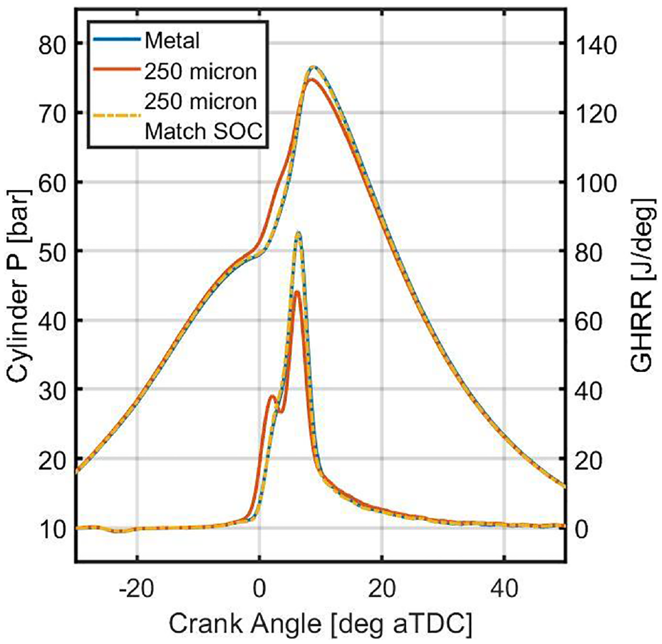
Cylinder pressure and gross heat release rate (GHRR) versus crank angle of the metal baseline, the matched intake temperature 250-micron Gen 1 piston, and the matched start of combustion (SOC) 250-micron Gen 1 piston at the 6 bar IMEPn operating condition.
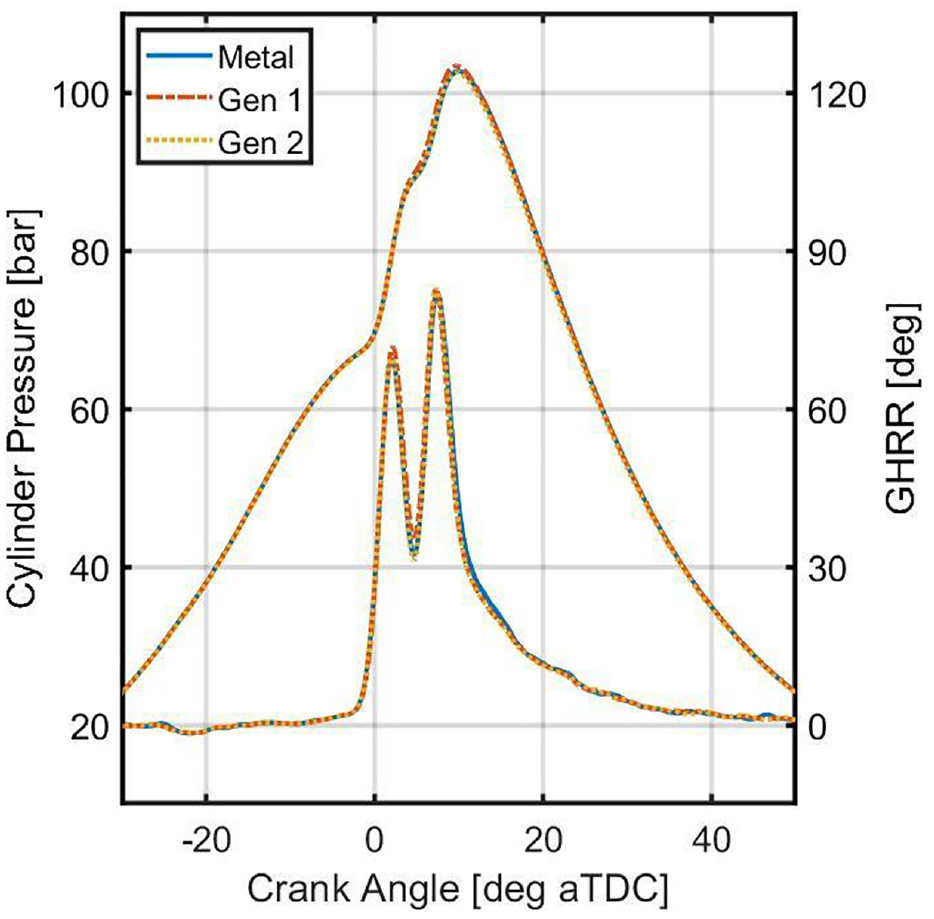
For the following comparisons, the intake temperature of the TBC cases was adjusted to match the start of combustion of the metal baseline. With identical injection strategies and closely matched thermodynamic conditions at the start of combustion, any differences observed during the combustion process may be attributed to the TBC surface properties. Figures 2 –4 show the cylinder pressure and gross heat release rate traces of the metal baseline, the 250-micron Gen 1 piston, and the 80-micron Gen 2 piston at 6, 10, and 15 bar IMEPn, respectively. Tables 4–6 show the indicated performance and emissions results of the metal baseline, the 250-micron Gen 1 piston, and the 80-micron Gen 2 piston at 6, 10, and 15 bar IMEPn, respectively.
Cylinder pressure and gross heat release rate (GHRR) versus crank angle of the metal baseline, the matched start of combustion (SOC) 250-micron Gen 1 piston, and the matched start of combustion (SOC) 80-micron Gen 2 piston at the 6 bar IMEPn operating condition.
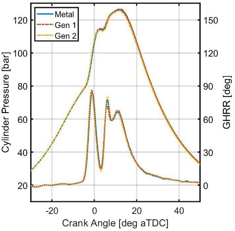
Cylinder pressure and gross heat release rate (GHRR) versus crank angle of the metal baseline, the matched start of combustion (SOC) 250-micron Gen 1 piston, and the matched start of combustion (SOC) 80-micron Gen 2 piston at the 10 bar IMEPn operating condition.
Cylinder pressure and gross heat release rate (GHRR) versus crank angle of the metal baseline, the matched start of combustion (SOC) 250-micron Gen 1 piston, and the matched start of combustion (SOC) 80-micron Gen 2 piston at the 15 bar IMEPn operating condition.
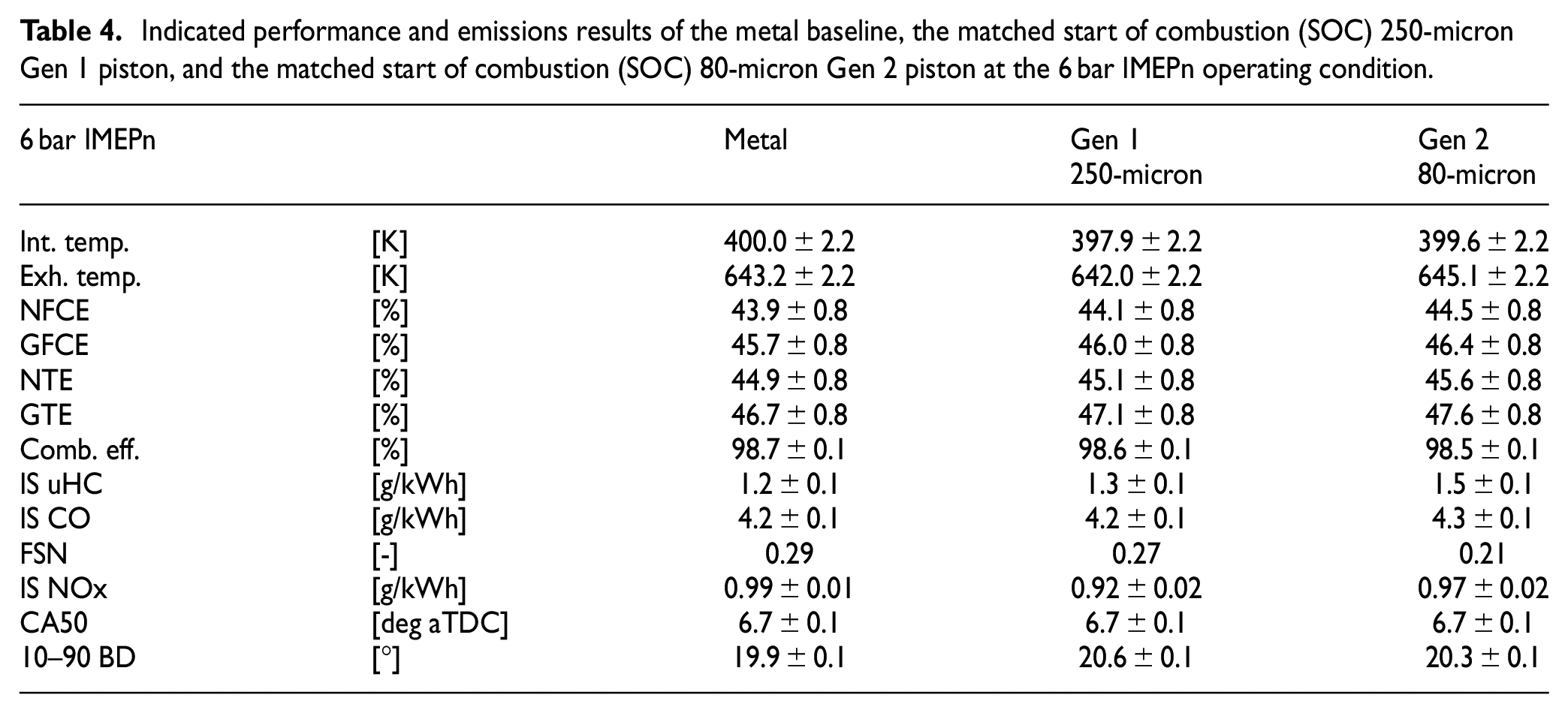
Indicated performance and emissions results of the metal baseline, the matched start of combustion (SOC) 250-micron Gen 1 piston, and the matched start of combustion (SOC) 80-micron Gen 2 piston at the 6 bar IMEPn operating condition.
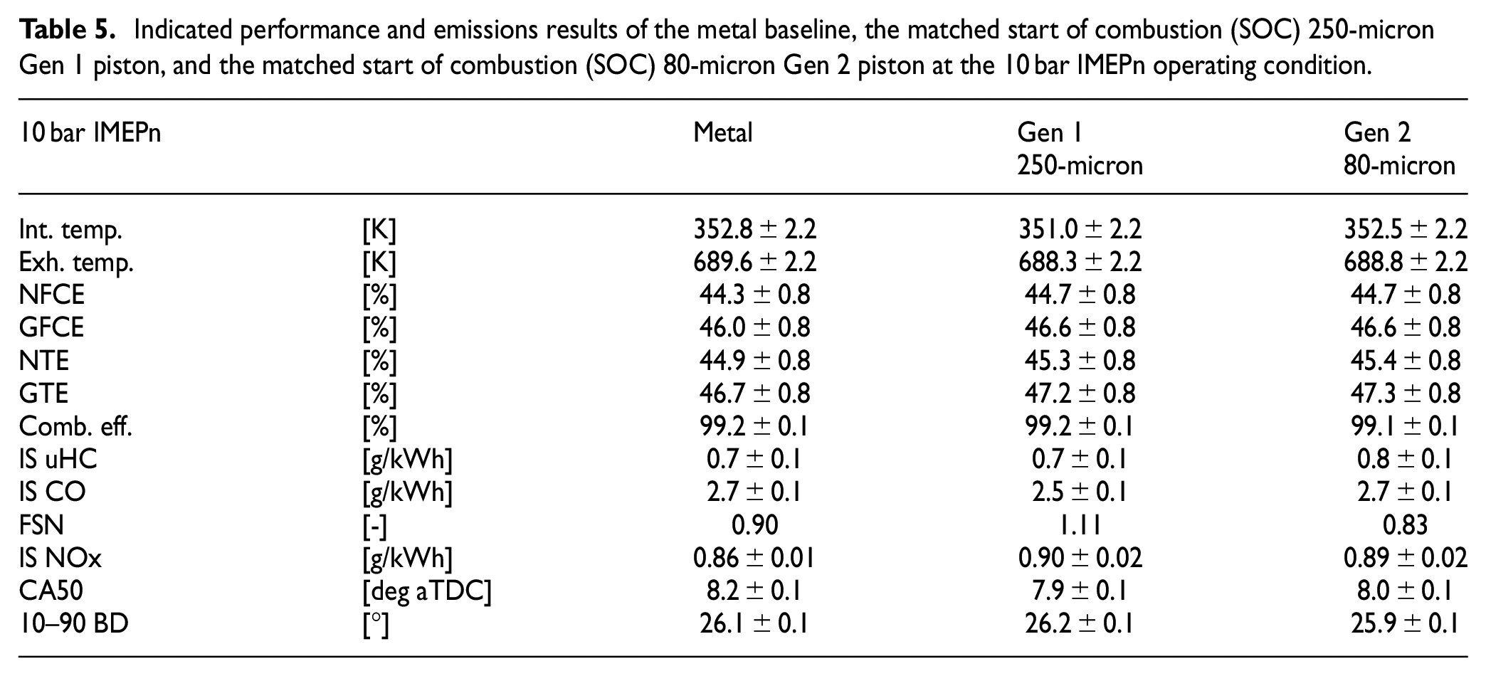
Indicated performance and emissions results of the metal baseline, the matched start of combustion (SOC) 250-micron Gen 1 piston, and the matched start of combustion (SOC) 80-micron Gen 2 piston at the 10 bar IMEPn operating condition.
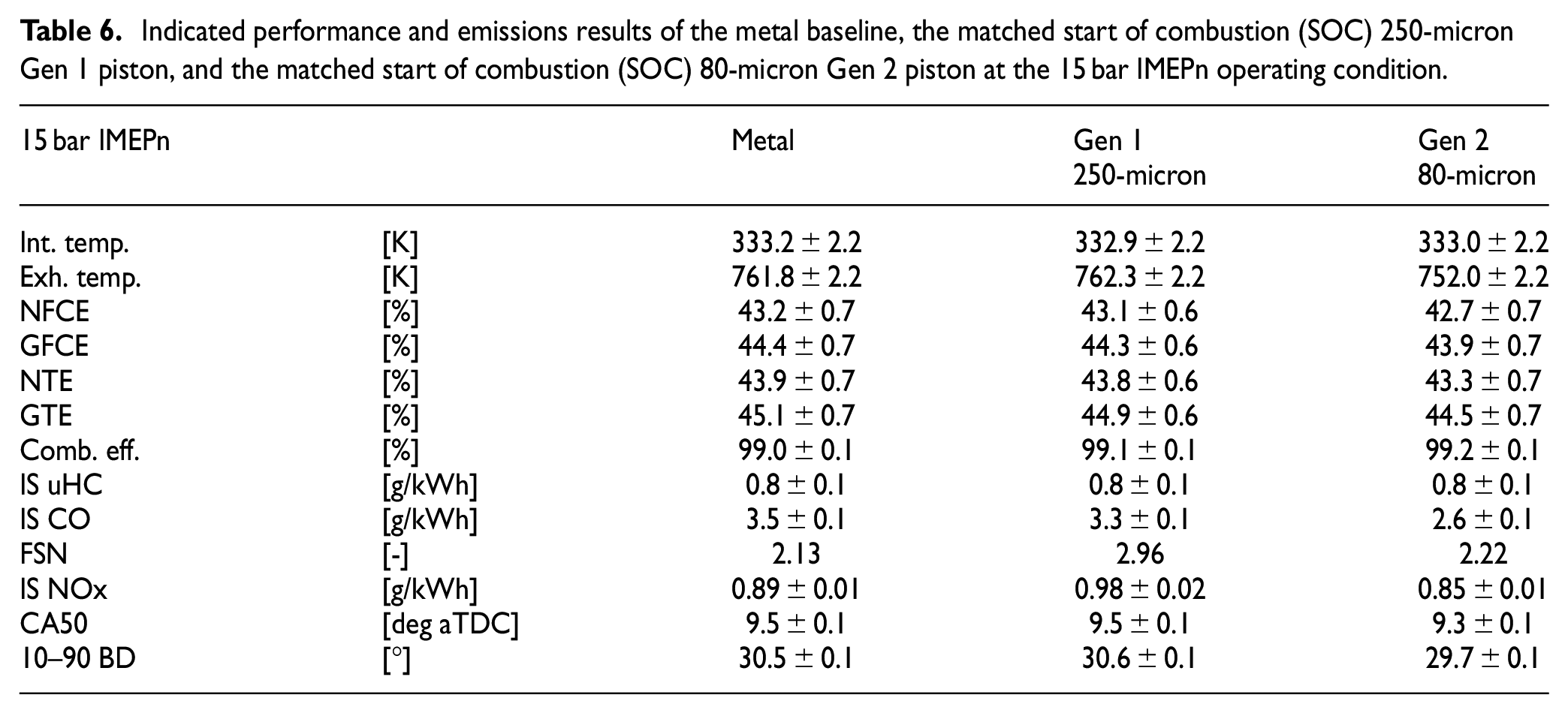
Indicated performance and emissions results of the metal baseline, the matched start of combustion (SOC) 250-micron Gen 1 piston, and the matched start of combustion (SOC) 80-micron Gen 2 piston at the 15 bar IMEPn operating condition.
The intake temperature requirement to achieve autoignition of gasoline decreases rapidly with pressure due to its cool flame reactivity. This is why the intake temperature decreases significantly as load increases in this work. Cool flame reactions also result in non-Arrhenius ignition behavior whereby an increase in temperature does not result in the expected decrease in ignition delay. This is because of a decrease in the cool flame reactivity. 29 When the sensitivity of ignition delay to temperature inverts, a negative temperature coefficient (NTC) region of the operating map emerges. This reduced sensitivity of autoignition to changes in temperature manifests here as a decreased sensitivity of start of combustion to charge heating. Unlike the Gen 1 material, the thickness of the Gen 2 material did not exceed its thermal penetrative depth (∼100 microns). Therefore, the intake temperature requirement of the Gen 2 piston did not decrease as much as the Gen 1 piston.
Previous research has shown mixed results on whether the application of TBCs experimentally results in an increase in exhaust temperature. 19 Yan et al. 30 showed with modeling that although a decrease in exhaust temperature may occur with TBCs due to differences in charge composition resulting from a lowered intake valve closing temperature, the exhaust enthalpy increases. Since the exhaust temperature is sensitive to dilution, experimental uncertainty in equivalence ratio and EGR fraction can result in higher variance in exhaust temperature than changes resulting from the TBC. Overall, the present results do not show a clear exhaust temperature trend.
Before discussing the efficiency changes resulting from the application of TBCs on the piston crown, a brief discussion of the uncertainty in efficiency measurement is given here. The expected gains in thermal efficiency achieved via the application of either coating on the piston crown only are modest 31 and are thus difficult to evaluate experimentally. A robust uncertainty analysis is performed on each experimental data point, which results in experimental uncertainties larger than the expected gain in efficiency. The large uncertainty shown for each efficiency value is largely sourced from the instrument error of the fuel flow measurement device. However, the fuel flow rate and efficiency at each steady state operating condition is highly repeatable, meaning that the instrument uncertainty, when evaluated at a given operating condition (i.e. fuel flowrate) is largely a bias error. This makes sense when considering that any uncertainty stemming from linearity error functions as a bias error when comparing the same fuel flow conditions. As such, comparing the efficiency of identical operating conditions, like each table shows, likely results in much smaller uncertainty values than those shown since the bias error will cancel out. Quantifying this bias error would require another highly accurate fuel flow rate device, which was unavailable for this work. Therefore, the uncertainties reported in each table are left as is, but a discussion of the difference in efficiency resulting from TBC application is still given, understanding the statistical significance is likely higher than reported. To demonstrate robust statistical significance of the results, gains at multiple operating conditions can be considered simultaneously.
Another brief aside on the reported efficiency is that four efficiency values are shown for each operating condition: net fuel conversion efficiency, gross fuel conversion efficiency, net thermal efficiency, and gross thermal efficiency. While the net fuel conversion efficiency is ultimately the efficiency that matters the most, looking at differences in thermal efficiency is useful for looking singularly at the thermodynamic difference in efficiency. Similarly, comparing the differences between gross and net efficiency help normalize out any small, non-negligible changes that occur in the pumping work, which may result from engine rebuild uncertainty and day-to-day variances in the test cell.
At 6 bar IMEPn, both the Gen 1 and the Gen 2 coatings showed an improvement in net fuel conversion efficiency. Both pistons also experienced a slight decrease in combustion efficiency in the form of increased uHC emissions. The Gen 1 piston experiences a 0.4 percentage point (pp) increase in gross thermal efficiency while the Gen 2 piston experiences a 0.9 pp increase compared to the metal baseline. At this operating condition, smoke emissions are low, thus there is no appreciable difference in smoke emissions resulting from either TBC. Overall, using an identical injection strategy and matching the start of combustion using the intake temperature, there was no appreciable difference in the heat release process of either coated piston case compared to the metal baseline.
At 10 bar IMEPn, both pistons experience a similar gain of 0.4 pp in net fuel conversion efficiency. Here, only the Gen 2 piston experienced a small combustion efficiency penalty compared to the metal baseline in the form of increased uHC emissions. The gross thermal efficiency gain of the Gen 1 piston at this operating condition was 0.5 pp, roughly the same amount as at 6 bar IMEPn. For the Gen 2 piston, the gross thermal efficiency gain was 0.6 pp, down noticeably from the 6 bar IMEPn case. The smoke emissions of the Gen 1 piston (FSN of 1.11) were somewhat higher than the metal baseline (0.90). The Gen 2 piston had a slight decrease in smoke emissions (FSN of 0.83) compared to the metal baseline. Using the same injection strategy and adjusting the intake temperature to match the start of combustion, the heat release process of both coated pistons behaved nearly identically to the metal baseline.
At 15 bar IMEPn, there was a net fuel conversion efficiency penalty with both pistons. With the Gen 1 piston, there was a 0.1 pp decrease in the net fuel conversion efficiency and a 0.2 pp decrease in gross thermal efficiency. The Gen 1 piston also experienced significantly higher smoke emissions (FSN of 2.96) compared to the metal baseline (FSN of 2.13), and noticeably higher NOx emissions. Figure 5 displays the mass probability distribution function versus particle diameter directly from the DMS 500 for all three pistons at 15 bar IMEPn. There it is clear that the Gen 1 piston produces significantly more soot mass in both the accumulation (small particle diameter) and agglomeration (large particle diameter) phases.
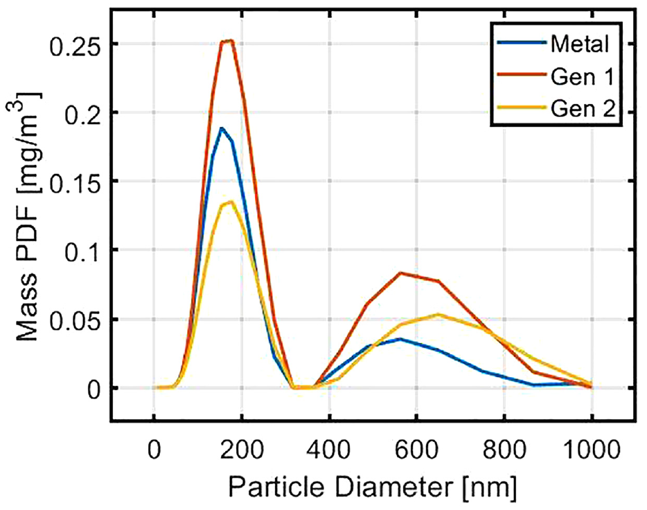
Mass probability distribution function (PDF) of soot mass versus particle diameter of the metal baseline, the matched start of combustion (SOC) 250-micron Gen 1 piston, and the matched start of combustion (SOC) 80-micron Gen 2 piston at the 15 bar IMEPn operating condition.
Looking at the heat release profile, with roughly the same pilot heat release process and the same injection parameters, the premixed spike of the main injection has a lower peak heat release rate compared to the metal baseline. Although it is not clearly visible from Figure 4, this would imply slightly more fuel in the diffusion burn, explaining the increase in smoke emissions. However, it is also known that TBCs can display some fuel storage effects due to small-scale surface roughness and porosity, which causes fuel adsorption and absorption, respectively, resulting in increased smoke emissions. 33 Although the target surface roughness of 2 Ra or lower should avoid this result, the difficulty in polishing the cusp of the bowl which experiences heavy fuel impingement may result in more fuel absorption. This operating condition has the highest injection pressure as well as the highest operating pressure, both of which would increase fuel storage propensity in the TBC. As the piston recedes from TDC, fuel captured by the TBC may be released in the combustion chamber, similar to fuel trapped in the crevice.
The Gen 2 piston demonstrated a significant net fuel conversion efficiency penalty of 0.5 pp at 15 bar IMEPn. CO emissions decreased by 25% compared to the metal piston and the smoke and NOx emissions remained comparable. There was no appreciable change in the heat release process that could explain these results. From Figure 5, the Gen 2 piston shows a decrease in the amount of soot mass in the accumulation phase, but an increase in the agglomeration phase.
Overall, these experiments demonstrated that on average, the Gen 1 piston showed an efficiency benefit with an emissions penalty while the Gen 2 piston showed significantly varied results, with large gains in efficiency at two operating conditions, but a significant efficiency penalty at the third. Compared to thermodynamic modeling results that coupled a 0D engine simulation with a 1D surface temperature solver, both coatings experienced higher than expected gains in thermal efficiency at 6 bar IMEPn. The modeling predicted ∼0.2 pp for the Gen 1 coating and 0.4 pp for the Gen 2 by coating the piston crown only, as shown in Figure 6, reproduced from Yan et al. 31 However, the model also predicted increasing efficiency gains as load increased, which is the opposite trend observed in this experimental work. While experimental uncertainty could contribute to some of this disagreement, the modeling assumptions of a spatially uniform surface temperature and of no convection vive could also contribute to this discrepancy. This will be discussed in more detail following the last set of experimental results below.
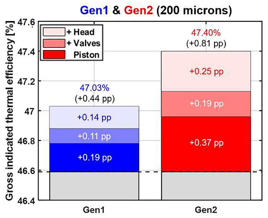
Gross indicated thermal efficiency for different coating coverage @ 1500 rpm, 6 bar IMEPg reproduced from Yan et al. 32
Hybrid Gen 1/Gen 2 coated piston
After testing each piston, the piston was removed from the engine and inspected for failure. The Gen 1 piston showed no signs of failure. The Gen 2 piston showed failure in several regions on the piston, as seen in Figure 7. Some of the results above, particularly the unexplained significant efficiency penalty at 15 bar IMEPn, may be explained by coating failure. Several subsequent iterations of the Gen 2 piston were made to address the various failure modes. While some failure modes were fixed with each iteration, such as failures in-plume and near the piston pip (i.e. the center point of the piston), no Gen 2 piston completely survived testing. In particular, failure in the bowl cusp region continually recurred. Failure in this region was attributed to poor adhesion of the spray to the bond coat on the vertical wall and to the sharp radius of curvature as the bowl transitions to the squish region. These failure modes are also hypothesized to be exacerbated by the fact that in this light-duty engine, there is significant piston-plume interaction, as seen in a CFD snapshot in Figure 8. This is due to constraints of the current project, which coupled a flat fire deck with a shallow bowl piston that was optimized for a GCI system with a pent-roof head. For more information on the CFD model, see Yan et al. 31
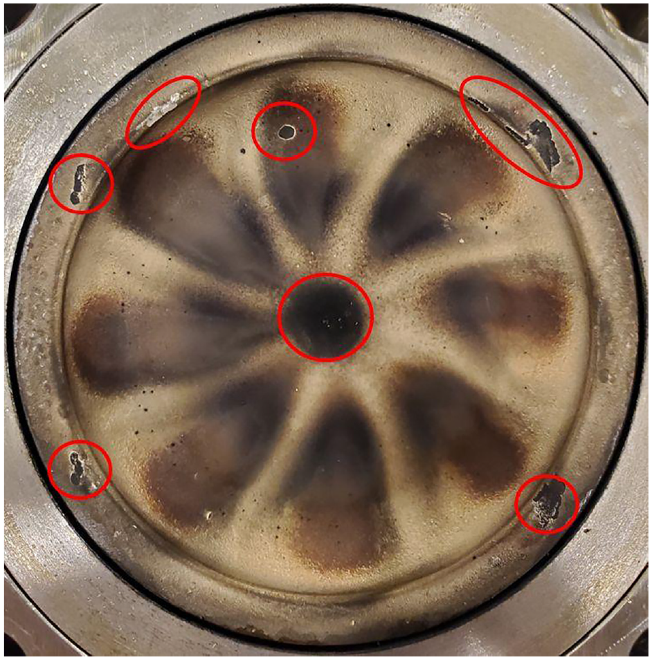
Gen 2 piston after testing with major coating failures highlighted in red.
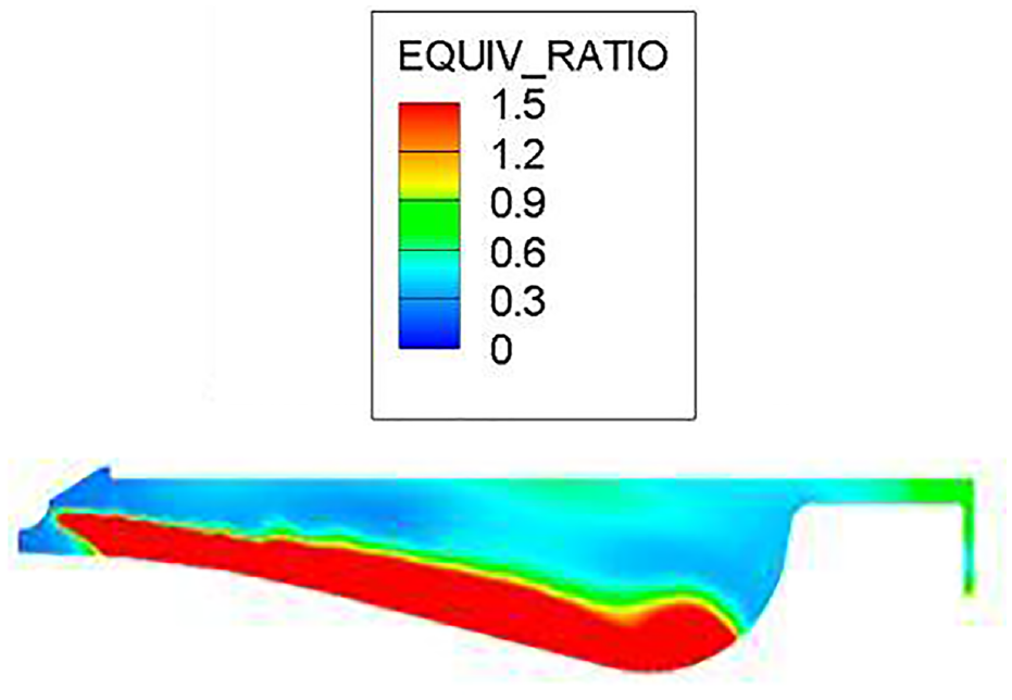
CFD snapshot of spray impingement on the piston crown.
Since the material properties of the Gen 1 coating are more favorable for durability, a final piston was sprayed, where the Gen 1 material was sprayed in the high failure-rate region in the bowl cusp, and the Gen 2 material was sprayed everywhere else on the piston. This coating, referred to henceforth the Gen 1/Gen2 hybrid TBC, has a thickness of 120 microns and is shown in Figure 9(a). Figure 9(b) shows the hybrid piston after testing and Figure 9(c) shows the hybrid piston after testing with combustion chamber deposits (CCDs) cleaned off. No failures or defects were detected in this coating after testing. One interesting observation from Figure 9 is that after testing, soot from each plume is clearly visibly deposited on the Gen 2 material on piston crown, and the region between plumes is relatively clean. Additionally, there are no CCDs on the Gen 2 material in the squish region. Although testing was only conducted for roughly 6 h, a clean metal piston under similar conditions would have some CCDs everywhere on the piston. The Gen 1 material in the bowl has CCDs along the entire stripe, both in and out of plume. After cleaning the piston, the Gen 1 material appears to remain more discolored than the Gen 2 material.
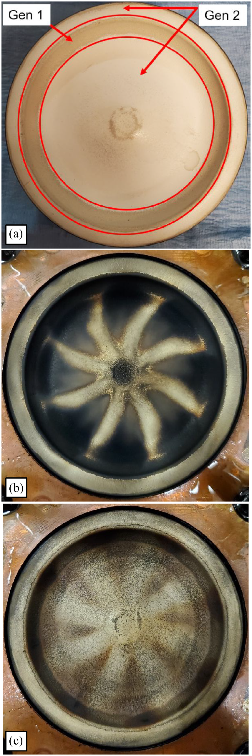
120-Micron Gen 1/Gen 2 hybrid piston: (a) before testing, (b) after testing, and (c) after testing with combustion chamber deposits cleaned off.
While there is nothing quantitative to conclude about these observations at this point, they may point to some interesting differences between the coatings. For example, the thickness of CCDs are known to be an equilibrium phenomenon between deposits forming and burning off. 33 When the surface temperature is elevated, this equilibrium shifts toward building thinner deposits. Since the Gen 2 coating is expected to swing significantly higher in temperature than the Gen 1 coating, at any given operating condition, CCD formation propensity may be diminished. Additionally, after cleaning, the Gen 1 material appears to have more CCDs that are “baked in.” This may simply be the result of the Gen 1 material sitting in a higher sooting propensity region of the piston – this is partially supported by the fact that in Figure 9(c), the CCDs on the small amount of Gen 1 material visible in the squish region cleaned off easier than in the bowl. However, this may also be connected to why the Gen 1 material demonstrated a clear increase in smoke emissions compared to the metal baseline or the Gen 2 material.
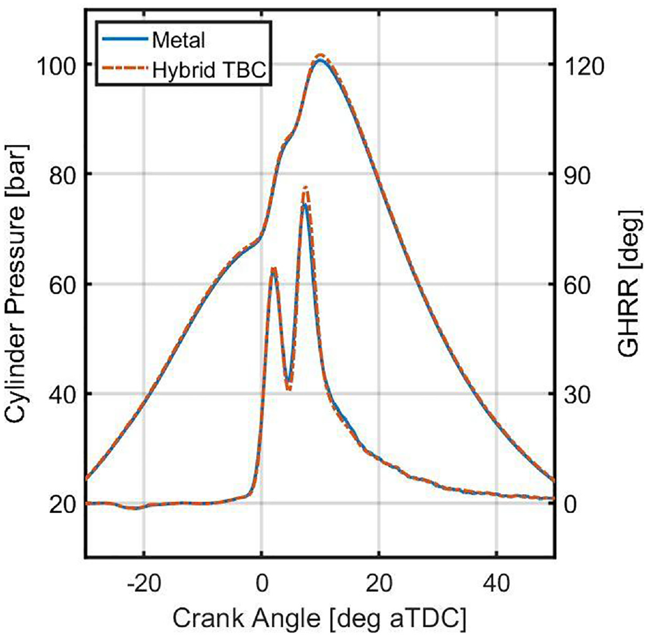
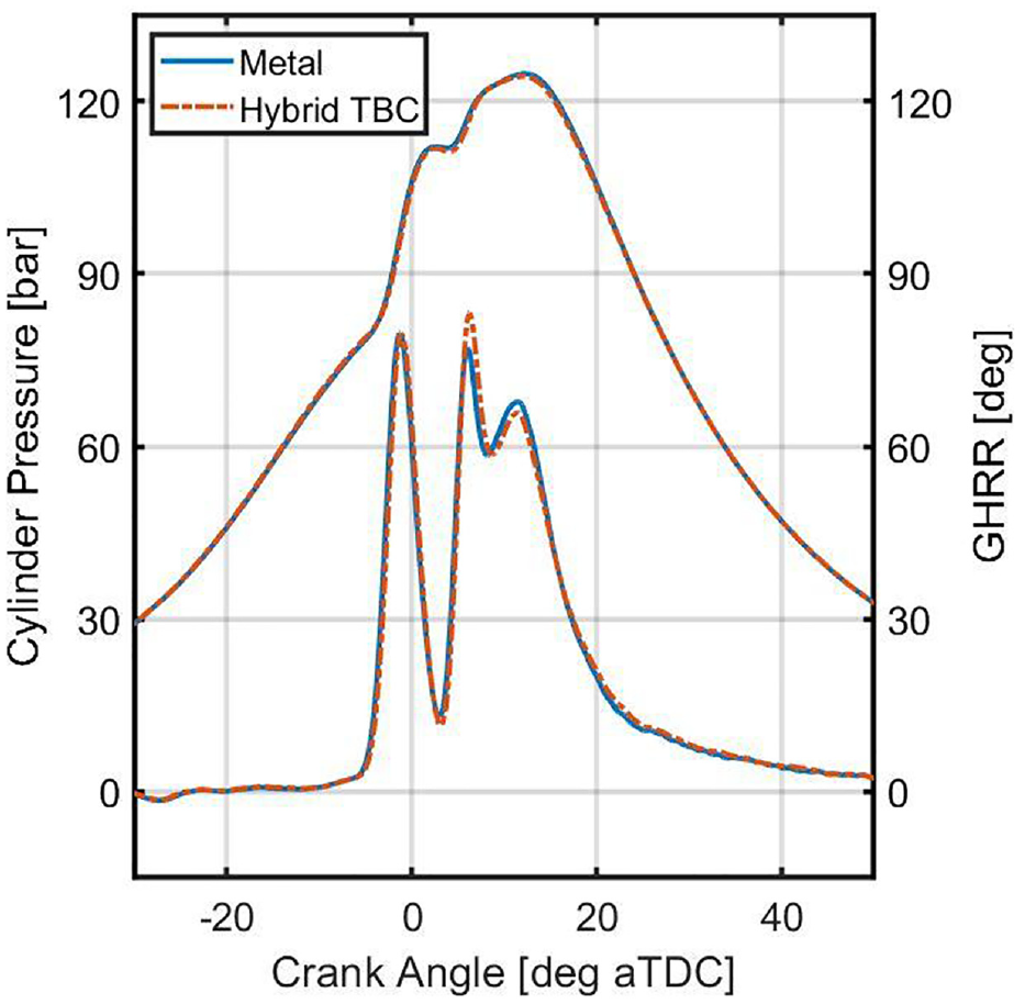
Figures 10–12 show the cylinder pressure and gross heat release rate traces of the metal baseline and the 120-micron Gen 1/Gen 2 hybrid piston at 6, 10, and 15 bar IMEPn, respectively. Table 7 shows the indicated performance and emissions results of the metal baseline and the 120-micron Gen 1/Gen 2 hybrid piston at all three operating conditions. Note that the indicated results of the metal baseline presented here are different than the one previously shown. After numerous Gen 2 piston coating failures, the engine was tuned up and a new metal baseline was established.
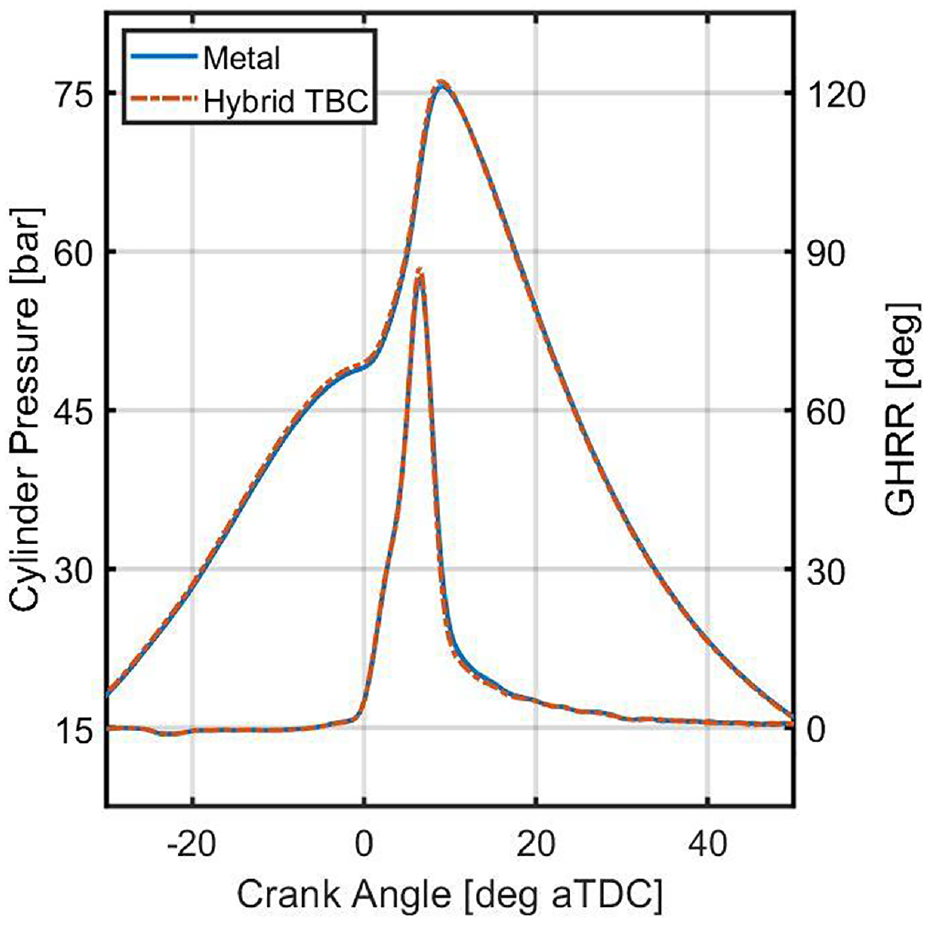
Cylinder pressure and gross heat release rate (GHRR) versus crank angle of the new metal baseline and the matched start of combustion (SOC) 120-micron Gen 1/Gen 2 hybrid at the 6 bar IMEPn operating condition.
Cylinder pressure and gross heat release rate (GHRR) versus crank angle of the new metal baseline and the matched start of combustion (SOC) 120-micron Gen 1/Gen 2 hybrid at the 10 bar IMEPn operating condition.
Cylinder pressure and gross heat release rate (GHRR) versus crank angle of the new metal baseline and the matched start of combustion (SOC) 120-micron Gen 1/Gen 2 hybrid at the 15 bar IMEPn operating condition.
Indicated performance and emissions results of the new metal baseline and the matched start of combustion (SOC) 120-micron Gen 1/Gen 2 hybrid.
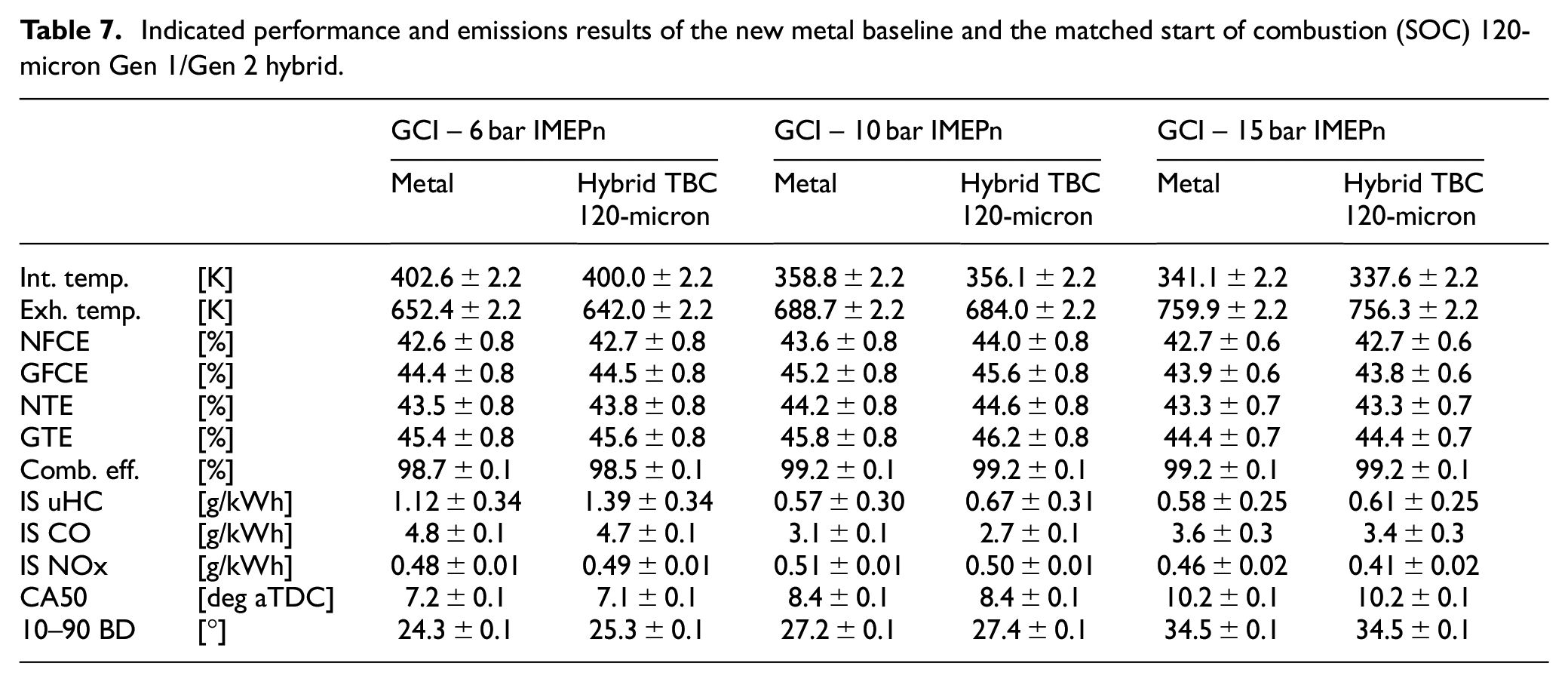
The intake temperature requirement to achieve the same start of combustion for all three operating conditions was lower with the hybrid coating compared to the metal baseline. Similarly, the exhaust temperature was lower for all three operating conditions with the hybrid coating. Compared to the previous two coatings tested, the Gen 1 coating section of the hybrid piston is thinner and the Gen 2 section is thicker. Since the total surface area of the coating is >80% Gen 2 material, increasing the total thickness of the Gen 2 material beyond its penetrative depth will result in more charge heating compared to reducing the thickness of the Gen 1 coating section. What is not explained is why the intake temperature requirement changed so significantly at 15 bar IMEPn, when previously no change was observed.
The net fuel conversion efficiency increased very slightly at 6 bar IMEPn (0.1 pp), more significantly at 10 bar IMEPn (0.4 pp), and then not at all at 15 bar IMEPn. At 6 bar IMEPn, there was a combustion efficiency penalty of 0.2 pp in the form of a ∼25% increase in uHC emissions. Thus, the gross thermal efficiency actually had a higher increase of 0.3 pp. At 10 and 15 bar IMEPn, the combustion efficiency was unchanged as the increase in uHC emissions was offset by a decrease in CO emissions. Overall, these results were somewhat similar to what would be expected of a hybrid Gen 1/Gen 2 coating – an increase in efficiency that is diminished at 15 bar IMEPn and an increase in uHC emissions.
The original metal baseline smoke dataset was recorded thrice throughout the various coated piston tests and showed high repeatability. Unfortunately, when re-baselining the metal piston for the hybrid piston, the smoke data from the DMS 500 showed highly inconsistent results compared to the previous datasets. Specifically, the smoke emissions of the new metal baseline were 30%–50% higher than previous datasets, with a large concentration of large particles up to the 1000 nm size. Since it is highly unlikely that this is physical, the smoke emissions for this new dataset were omitted.
Discussion and next steps
The thermal efficiency gains shown in the above experimental results were roughly equal to or exceeded the predicted gains from a priori modeling results at 6 and 10 bar IMEPn. There was a clear increase in uHC emissions with both the Gen 1 and Gen 2 coatings, though only the Gen 1 coating appeared to have a negative impact on soot emissions. In GCI, this uHC problem is mostly of concern at the lower end of the load range where the partially premixed combustion phase may be a significant fraction of the total released heat. This leaves room for potential improvement of the coating, provided that the uHC emissions can be addressed at the coating surface without sacrificing the low thermal inertia of the coating. If so, the thermal efficiency gain observed can be compounded with a combustion efficiency gain to further elevate the net fuel conversion efficiency increase due to the TBC.
At high load, there was no thermal efficiency gain observed but rather a potential penalty. The reduced order model predicted an efficiency gain at this condition, which suggests that there is some phenomenon that is happening in the experiment that the reduced order model does not capture. At this point, the authors can only speculate why this may be the case. Babu et al. 34 showed that the average surface temperature of a low thermal inertia coating could exceed 800 K in mixing-controlled combustion. Moser et al. 35 further showed that the surface temperature of a low thermal inertia coating can reach 1200 K in mixing-controlled combustion directly under the plume. While the science is not clear as to what degree convection vive impacts the performance of TBCs, if the surface temperature under the plume is in excess of 1000 K, it is possible that the thermal boundary layer is significantly impacted and hot enough to facilitate chemistry. With this in mind, convection vive could perhaps be operating condition dependent, especially in GCI where the low loads are generally more premixed and the high loads are a larger fraction of diffusion burn. When the injection pressure and the amount of fuel in the diffusion burn is higher, a convection penalty in-plume may outweigh a heat transfer reduction out of the plume. This may be exacerbated by spray impingement. Designing experiments to provide direct evidence to prove or disprove the theory of convection vive is difficult. Similarly, the boundary layer assumptions made in 3D CFD are currently ill-equipped to shed insight into this problem. These results, and others in the literature, provide continued motivation to develop experimental and computational techniques to explore questions related to TBCs and convection vive.
For GCI combustion, these results show that in the low and medium load range, tangible efficiency gains are achievable through the use of TBCs. The gains in this work are likely to increase by coating the head and valves as well, though direct experimental evidence is needed to quantify, which the authors are working toward as part of this continuing project. Part of the difficulty in coating valves with a wide spray angle injector is that the TBC will protrude into the combustion chamber and can disrupt the spray plume. Pre-machining the valves to accommodate the TBC is difficult because they are made of hardened steel. These results also point toward the importance of co-optimization of the combustion chamber geometry and the spray with the challenges associated with TBCs in mind. Whereas previous co-optimization of piston and spray for a light-duty GCI engine did not directly penalize spray impingement, 36 this work implies that care should be taken to keep the spray off the coating surface. Specifically, impingement of the PPCI-phase injection increase uHC emissions and impingement of the diffusion-phase injection may increase convection vive, especially at high load.
Conclusions
In this work, three pistons coated with low thermal inertia thermal barrier coatings (TBCs) were experimentally tested in gasoline compression ignition (GCI) on a single cylinder, light-duty research engine. One piston was coated with a 250-micron commercially available thick “Gen 1” material, Gadolinium Zirconate. A second piston was coated with an 80-micron thick proprietary “Gen 2” material. The Gen 1 coating displayed a slight uHC emissions penalty and a significant smoke penalty. The Gen 2 coating displayed an uHC emissions penalty but no smoke penalty. Both the Gen 1 and Gen 2 coatings displayed a fuel conversion efficiency benefit at 6 and 10 bar IMEPn and an efficiency penalty at 15 bar IMEPn. The Gen 1 coating proved durable while the Gen 2 coating experienced continual coating failure in the cusp of the bowl.
To address the durability issue of the Gen 2 coating, a third piston was experimentally tested that was sprayed with the Gen 2 coating everywhere except the high failure bowl cusp region, where the Gen 1 material was sprayed instead. This hybrid coating demonstrated an uHC penalty, no smoke penalty, a thermal efficiency benefit at 6 and 10 bar IMEPn, and no change in efficiency at 15 bar IMEPn. These results provide some indirect evidence of a convection vive effect of the impinging diffusion flame as a potential explanation for why the efficiency benefit disappears at high load. Overall, these results show promise for coating combustion chamber surfaces in GCI engines. The remaining challenges include improving surface sealing to mitigate the uHC penalty in the partially premixed phase of combustion and decreasing spray impingement on the piston crown.
Footnotes
Declaration of conflicting interests
The author(s) declared no potential conflicts of interest with respect to the research, authorship, and/or publication of this article.
Funding
The author(s) disclosed receipt of the following financial support for the research, authorship, and/or publication of this article: This work was funded by a contract from Aramco Services Inc. to Clemson University.