
Abstract
Shipping is one of the most efficient transportation modes for moving freight globally. International regulations concerning decarbonization and emission reduction goals drive rapid innovations to meet the 2030 and 2050 greenhouse gas reduction targets. The internal combustion engines used for marine vessels are among the most efficient energy conversion systems. Internal combustion engines dominate the propulsion system architectures for marine shipping, and current marine engines will continue to serve for several decades. However, to meet the aggressive goals of low-carbon-intensity shipping, there is an impetus for further efficiency improvement and achieving net zero greenhouse gas emissions. These factors drive the advancements in engine technologies, low-carbon fuels and fueling infrastructure, and emissions control systems. This editorial presents a perspective on the future of ship engines and the role of low-life cycle-carbon-fuels in decarbonizing the marine shipping sector. A selection of zero-carbon, net-zero carbon, and low-lifecycle-carbon-fuels are reviewed. This work focuses on the opportunities and challenges of displacing distillate fossil fuels for decarbonizing marine shipping. Enabling technologies such as next-generation air handling, fuel injection systems, and advanced combustion modes are discussed in the context of their role in the future of low-CO2 intensity shipping.
Keywords
Introduction
The global efforts to mitigate the adverse effects of global climate change requires developing and deploying low-carbon-intensity processes for all energy consumption sectors. A rapid evolution of propulsion system technologies 1 across on-road, off-road, rail, marine, and aviation transportation must achieve significant decarbonization and limit the global temperature rise to 1.5°C. 2 Marine transport accounts for over 80% of global trade and about 3% of global carbon emissions. According to IEA (https://www.iea.org/energy-system/transport/international-shipping) it is 2% of energy-related carbon emissions. Also, according to OECD (https://www.oecd.org/ocean/topics/ocean-shipping/) the global trade is 90%, not 80%. The maritime shipping industry includes international (also referred to as ocean-going or blue-water ships), inland, and coastal waterways (i.e. small vessels) for transport. Currently, the international shipping sector member states aim to adhere to the stringent International Maritime Organization (IMO) targets for reducing greenhouse gas (GHG) emission levels by 50% in 2050 compared with 2008 levels. 3 Emissions of CO2 must be reduced by at least 40% (by 2030) and 70% (by 2050). 4 IMO discussions of future standards include well-to-wake and account for fuel production in terms of carbon footprint. Also, the European Union (EU) recently added the maritime sector to its Emissions Trading System framework to cut GHG emissions (including CO2, CH4, and N2O) by 55% by 2030 (compared with 1990 levels). Existing EU shipping emission regulations only consider tank-to-wake carbon footprints (excluding fuel production).
Marine propulsion systems can be divided into two main categories: medium- or high-speed, four-stroke engines (used in smaller vessels) and low-speed, two-stroke engines (standard in large ocean-going marine vessels). Figure 1 shows the relative fuel consumption in the marine sector broken down by ship main engine type. The main propulsion engines for large container, bulk carrier, and tanker vessels are the largest low-speed, two-stroke engines (<12 m tall), which generate up to 80 MW; medium-speed, four-stroke engines in the 1–20 MW range are used for many other classes of shipping including LNG tankers, fishing vessels, ro-ro and ro-pax, and cruise ships; and high-speed, four-stroke engines generating <500 kW power smaller vessels in inland/coastal applications. Figure 2 illustrates the size scale across the marine engines used in these vessel types.
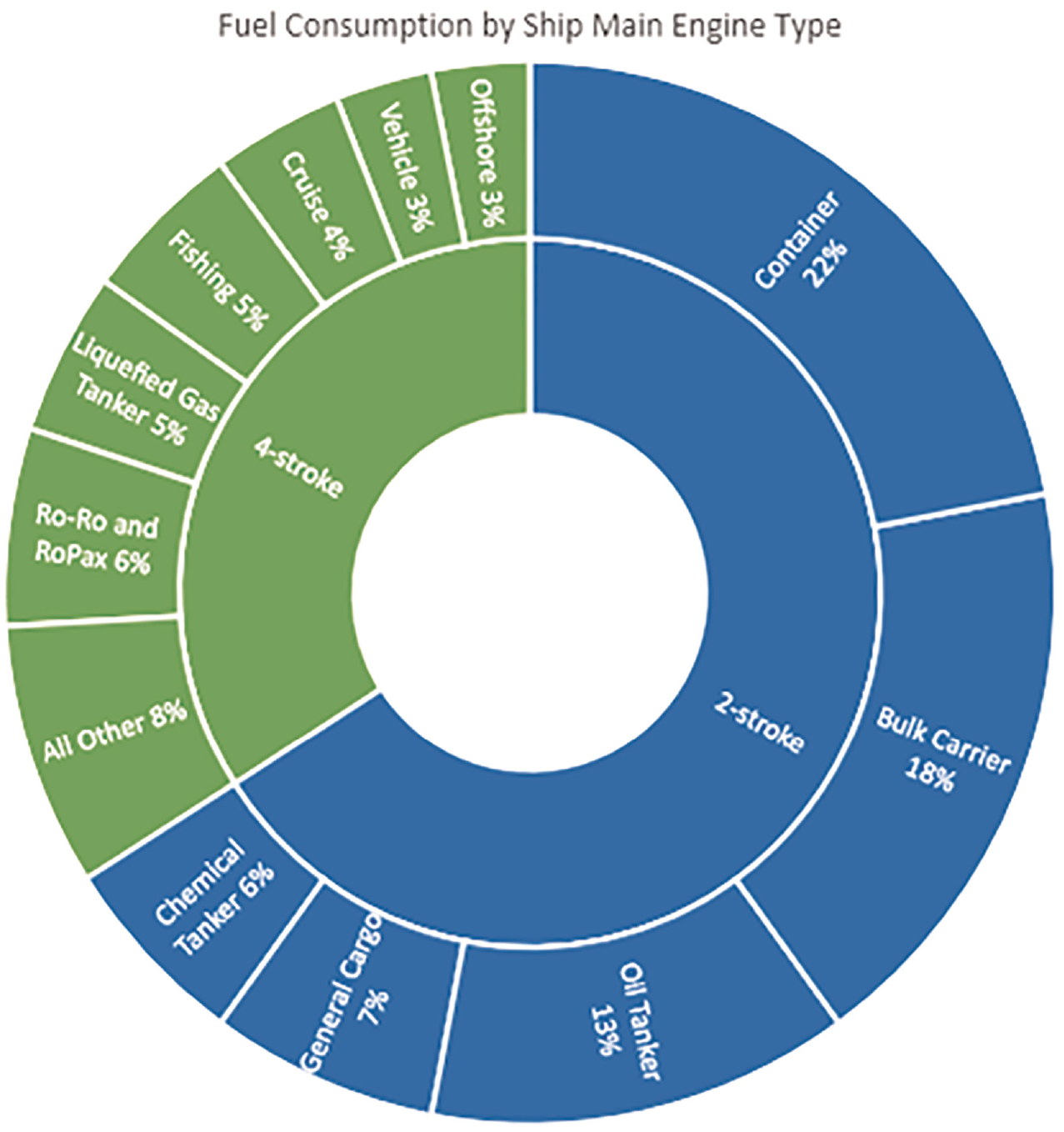
Fuel consumption by primary engine and vessel type for marine shipping. Data from Concawe, “Marine Fuel Facts.” 5
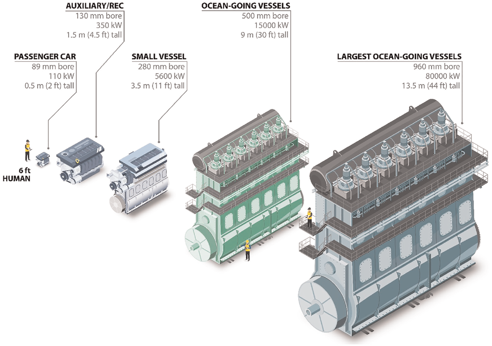
The size scale of marine engines used across all vessel types.
The low-speed, two-stroke, crosshead main propulsion engines used in large, ocean-going cargo vessels are among the world’s most efficient energy conversion devices. Modern, IMO Tier II and III, NO x -compliant diesel and dual-fuel configuration engines achieve thermal efficiencies of 50–55%.6,7 Auxiliary electrical power generation, using lower-efficiency, medium- or high-speed diesel engines, accounts for additional fuel consumption (6–13.8% of the propulsion power). 8 Waste heat recovery systems can recover up to 10% of the fuel energy from the main propulsion engines.9,10 This can reduce the need to operate auxiliary power generators and oil-fired boilers when the ship is underway, yielding a peak overall system efficiency of 60–65%.
With the increasing relevance of the NO x /efficiency trade-off, two-stage turbocharging has made inroads for four-stroke engines, yielding efficiency improvements through the higher peak cylinder pressures enabled by higher intake pressures. For two-stroke engines, the scavenging process largely decouples peak cylinder pressure from increases in intake pressure (increased intake pressure causes more mass flow through the engine and additional over-scavenging), and two-stage turbocharging has not yielded the same efficiency gains in these engines.9,11,12 More details on air handling systems are covered in a later section.
Four- and two-stroke compression-ignition engines are the most advanced propulsion application engines regulated by various emissions regulations across globe using a combination of modern engine control systems and emissions reduction systems. The long shipping routes, power density requirements, and use of a wide variety of vessels present difficulties in decarbonizing the maritime shipping sector. Using different propulsion systems across international borders creates challenges in meeting emissions regulations. Because of hydrocarbon fuels’ wide availability, the marine transport industry relies on heavy fuel oil (HFO) or marine gas oil (MGO). While dual-fuel LNG and methanol engines are gaining some market share, the low-speed two-stroke and medium-speed four-stroke main propulsion engines are most commonly fueled by HFOs in international waters and MGO within emission control areas (ECAs) where fuel sulfur limits apply. Medium- and high-speed four-stroke auxiliary engines on these ships may be fueled by marine diesel oil (MDO, onboard blends of HFO and MGO) or MGO. High-speed diesel engines are typically fueled with MGO or ultra-low sulfur diesel (ULSD) depending on the coastal or inland application.
Emission regulations in international shipping have been mainly the purview of the IMO, which regulates shipping in international waters and has also incorporated ECAs with more stringent standards in some territorial waters. A significant emphasis of IMO regulations has historically been controlling the fuel sulfur content to reduce the SOx emissions that lead to acid rain. Figure 3 shows IMO fuel sulfur limits: note the latest standard of 0.5% in international waters (implemented in 2020) and the maximum limit of 0.1% in emission control areas.
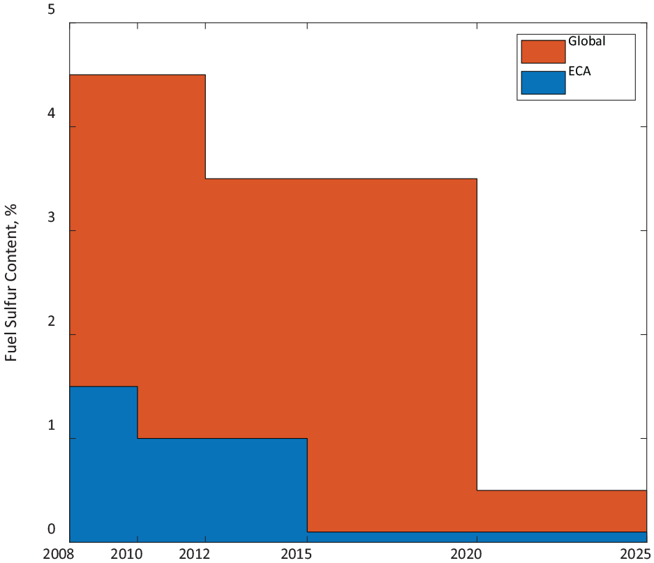
IMO fuel sulfur regulations time line.
The IMO also regulates NOx emissions in three tiers, with Tiers I and II applying globally and Tier III applying within NOx emission control areas (NECAs). Table 1 shows the NOx limits for each tier based on engine rated speed. Tier III currently applies in the North American and US Caribbean NECA for vessels with keel-laying after January 2016 and in the Baltic and North Sea NECAs for vessels with keel-laying after January 2021. Tiers I and II compliance have been obtained through advanced fuel injection strategy. In contrast, Tier III compliance typically requires either selective catalytic reduction (SCR) or exhaust gas recirculation (EGR) for diesel engines. Low-pressure, dual-fuel natural gas (NG) engines operating on the Otto cycle can meet Tier III regulations when operating in gas mode without SCR or EGR. In inland waterways, additional local regulations such as the US Environmental Protection Agency (EPA)’s Tier IV regulations and the EU’s Stage V regulations typically have significantly stricter NOx + hydrocarbon (HC) and particulate matter (PM) emission standards than those enforced internationally by the IMO.
IMO NOx emissions limits. n is the engine’s rated speed in rpm.
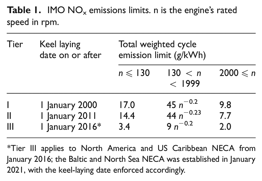
Tier III applies to North America and US Caribbean NECA from January 2016; the Baltic and North Sea NECA was established in January 2021, with the keel-laying date enforced accordingly.
For ocean-going vessels, black carbon (i.e. soot) contributes to 21% of GHGs on a 20-year CO2-equivalent basis. 10 However, in previous shipping emission regulation standards, black carbon emissions were not considered, so IMO focuses on future black carbon reductions. In the Antarctic polar region, HFOs are banned for transportation. According to the Institute of Electrical and Electronics Engineers (IEEE), to meet the CO2 emissions reduction target, 50% of marine engines must be operated on alternative fuels by the mid-2040s. 13 These engines can be in service for many years and are projected to be vital for shipping in the future.
The retrofit solutions and new engine system technology developments need to be investigated for decarbonizing the shipping industry. With battery propulsion systems, 100% electrification is feasible on short-range voyages with the possibility of battery recharging. Such systems present challenges with ocean-going vessels because a state-of-the-art Lithium Ion (Li-ion) battery’s energy content (kWh/kg) is approximately 50 times smaller than that of liquid fuels. Decarbonizing shipping requires the implementation of zero-carbon and low-lifecycle-carbon fuels (LLCFs), such as ammonia (NH3) and methanol. Several different LLCFs suitable for marine use are being investigated for commercial viability. Challenges with using alternative fuels in the maritime shipping industry include safety regulations global availability. This section focuses on the technical issues for implementing potential green alternative fuels such as gases (e.g. NG, hydrogen, and propane), alcohols (methanol, ethanol, and butanol), and bio-derived diesels (including biodiesel, renewable diesel and bio-intermediates). These fuels must be transportable, storable, and propel large ship engines across the oceans. The marine transportation engine must operate under economically sustainable, single- or dual-fuel combustion modes in varying fuel availability conditions. A pilot ignition source for example, HFO, MGO, biodiesel, or renewable diesel (i.e. <15% energy basis fuel fractions) – can be used along with a LLCF to achieve high carbon reductions. The development of dedicated fuel injection and combustion systems to withstand fuel toxicity and corrosiveness, low lubricity, and vapor pressure is required for marine engines using these alternative fuels.
For the selection of vessel propulsion systems, a techno-economic assessment is crucial. In recent years, renewable fuel use in maritime applications has been the subject of many publications.14–20 In many of these assessments, the vessel’s operational profile was unknown, and the engine’s rated power was chosen at the beginning of the assessment. Several tools, including the Large Engines Competence Center (LEC) ENERsim 21 and ABS SIM, provide simulation-based optimization of shipping energy systems. These tools couple various marine transportation system components, including energy sources, conversion, and use in ships and ports.
Finally, the best technology will depend on technological feasibility, space and weight constraints onboard the vessel, ship types and routes, bunkering options, operational profiles, legislative requirements, and transport costs. Transport costs also include capital expenditures, fuel and lost cargo costs, and potential carbon taxes. The research and development in ship propulsion regarding cost and environmental impact focuses on renewable fuels and the thorough assessment of various technology solutions. A recent US Department of Transportation report summarized spill behavior, detection, and mitigation for emerging, nontraditional marine fuel use over the next 30 years. 22
This editorial paper highlights the current trends in emerging internal combustion (IC) engine fuels and combustion modes, pointing out the main challenges, advantages, and drawbacks of the leading engine decarbonization solutions under investigation as economically feasible. The following discussion starts with a summary of combustion systems, followed by hydrogen and ammonia as energy carriers and low-carbon fuels (methanol, dimethyl ether, liquified natural gas (LNG), and bio-derived and synthetic drop-in fuels).
LLCFs for reducing CO2 intensity of shipping
Combustion systems and LLCFs
LLCFs for marine engines are classified as low or moderate-to-high cetane depending on the type of combustion system. Moderate-to-high cetane alternative fuels, including MGO or HFO drop-ins, allow for minimal-to-no changes in the fuel injection system and combustion chamber design. These fuels include renewable diesel, 23 bio-diesel blends, and potentially upgraded bio-oils and bio-crudes derived from pyrolysis or hydrothermal liquefaction. 24 Non-drop-in, moderate-to-high cetane fuels include dimethyl ether (DME) and polyoxymethylene ethers, which require different fuel injection timings and compatibility materials for handling.
Low-boiling-point and low-cetane fuels often apply to prechamber or spark ignition engines. Several ignition system configurations are already mature for LNG, propane, alcohols, and to a lesser extent, hydrogen-fueled, small, four-stroke engines. These engines lag in meeting the same torque characteristics as their diesel counterparts because at high engine loads in deflagration-based combustion systems, the engine shows a knocking effect. However, the dual-fuel combustion mode uses a diesel pilot in a mixing rate–limited combustion to retrofit the existing compression ignition engine applications. With dual-fuel combustion systems, advanced modes like reactivity-controlled compression ignition (RCCI), 25 high-pressure direct injection (HPDI), 26 or direct dual-fuel stratification 27 and dual-fuel strategies are possible. With low-boiling-point and low-cetane fuels, show advanced combustion modes, such as partially premixed compression and gasoline compression ignition (GCI) could be observed in laboratory scale experiments. Figure 4 illustrates the range of different types of combustion systems using a four-stroke engine. Although prechamber spark ignition (PCSI) systems are noted in the figure, they are not covered in this editorial.
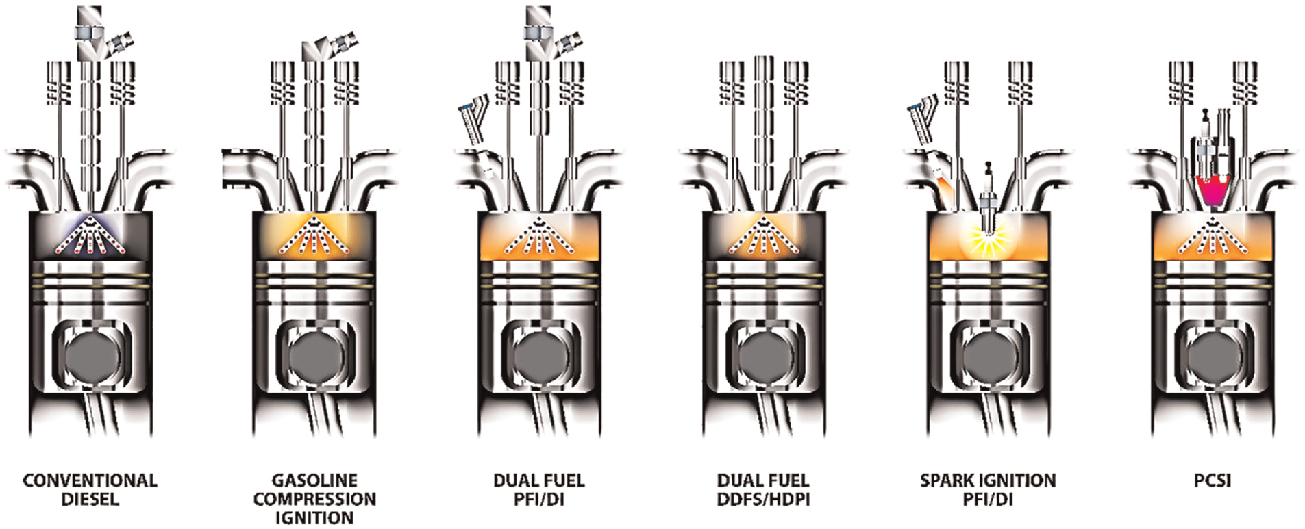
Combustion diagrams illustrate a range of different combustion strategies in a four-stroke engine. Adapted from Dempsey et al. 29
A significant challenge in establishing a decarbonization strategy for the entire shipping industry comes from the wide variety of combustion concepts in operations, from a small bore (<250 mm), four-stroke, high-speed engine to a large-bore (>500 mm), two-stroke, low-speed engine. Small-bore diesel engines have a centrally mounted fuel injector with a symmetric fuel nozzle pattern and an axisymmetric reentrant step-lipped, bowl-shape piston. In contrast, large, two-stroke engines have multiple injectors mounted in the periphery of the cylinder with asymmetric nozzle configurations and a shallow combustion bowl shape. Large, two-stroke engines rely on the swirl flow generated during scavenging to drive the combustion rates, and small-bore, four-stroke engines heavily rely on high injection rates and spray-bowl interactions. Figure 5 illustrates the differences between a four- and two-stroke engine.
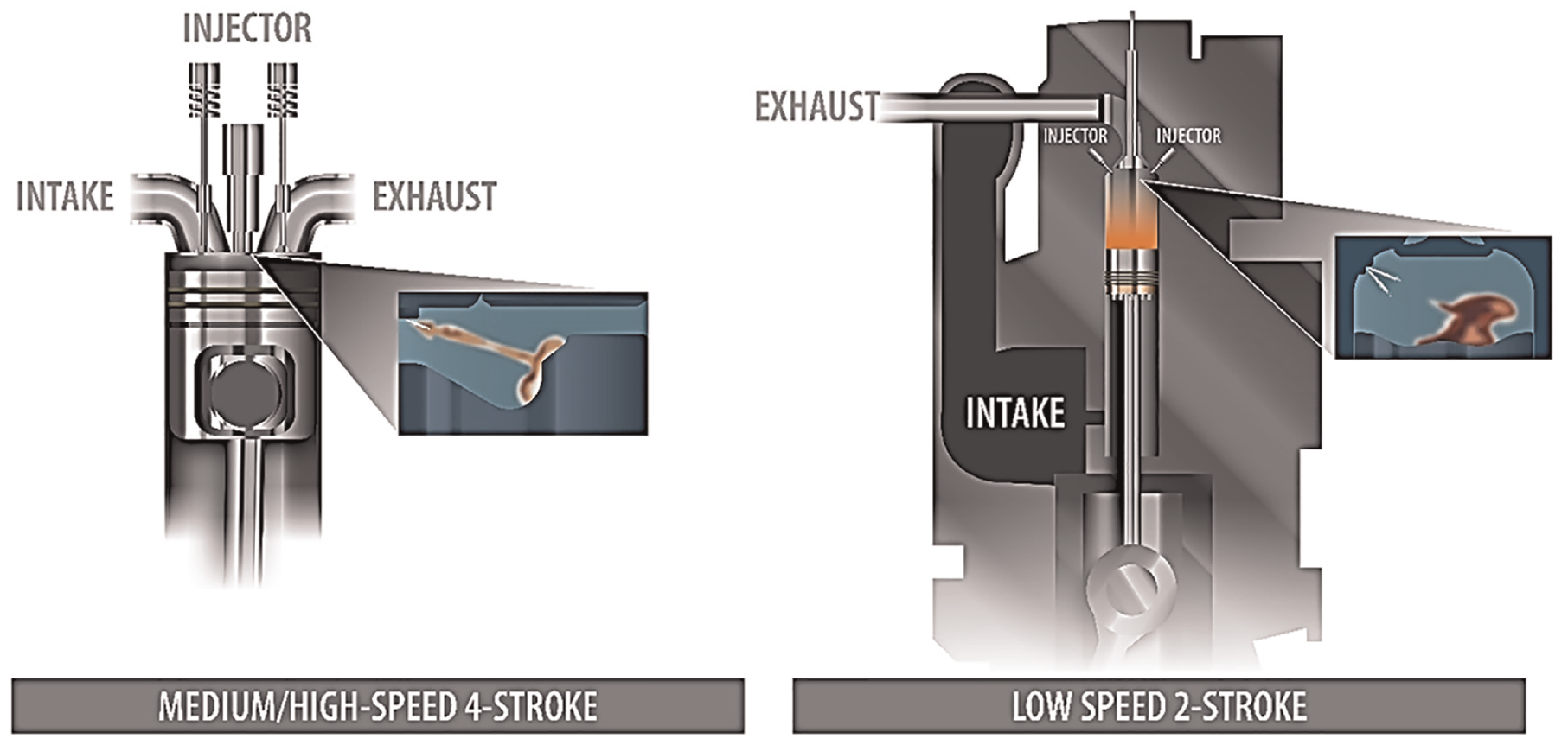
A comparison of the (left) four-stroke combustion chamber and (right) crosshead two-stroke combustion chamber with piston geometries and spray. Inserts adapted from Kalghatgi. 28 Images not to scale.
The large, low-speed, two-stroke engines have a 300–1000 mm bore diameter range with a 1–80 MW power output. Four-stroke engines are used for main propulsion engines in smaller vessels and auxiliary power in larger vessels. The bore sizes of four-stroke main propulsion engines range from 130 mm (recreational vessels), 250 mm (locomotives), and greater than 350 mm (large-size engines); bore diameters of low-speed, two-stroke engines range between 500 and 1000 mm. Figure 6 illustrates the marine piston size scale and type across these engine classes.
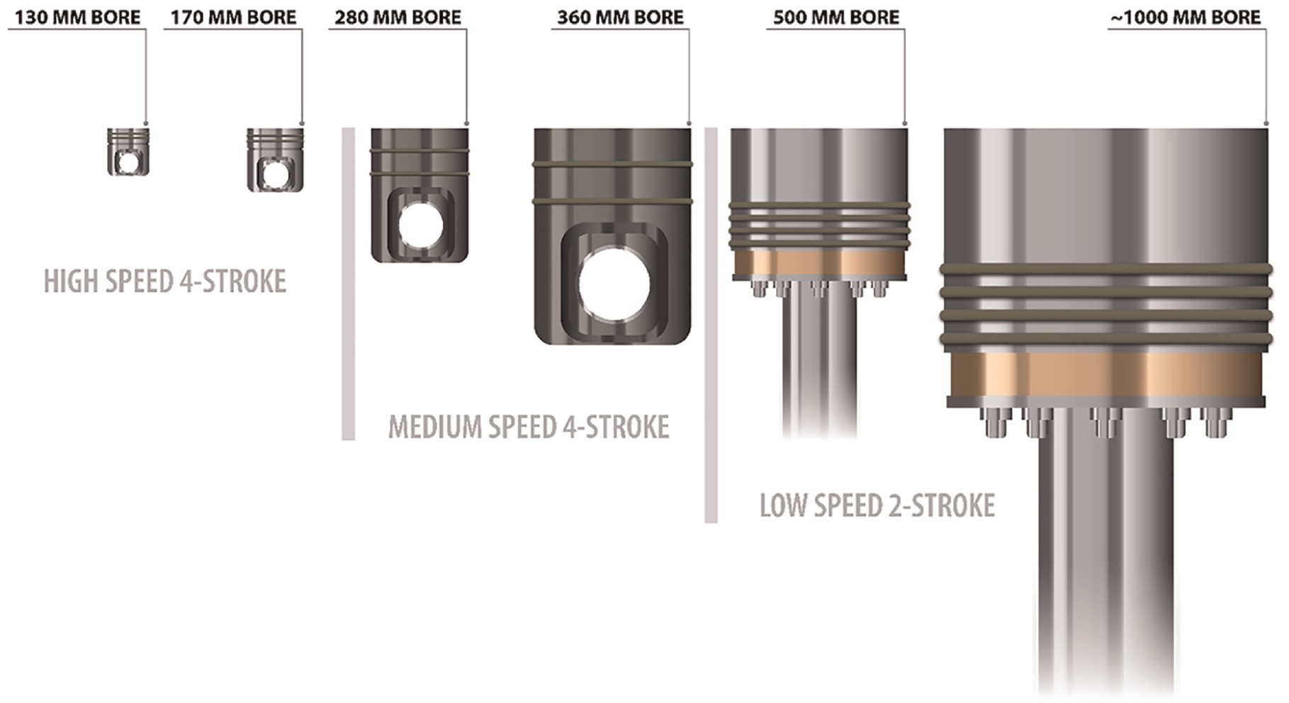
Size scale of marine engine pistons across four-stroke and two-stroke classes.
The substantial differences in the combustion timescales between the different engines directly result from these differences. The mean piston speed of both engines will be similar; due to the physical size of large, two-stroke engines, their rotational speed will thus be lower. Therefore, a substantially longer wall-clock time is available for fuel mixing and combustion with the large, 2-stroke engines. Figure 7 compares in-cylinder pressure and apparent heat release rates, predicted using computational fluid dynamics (CFD). A Cummins ISB engine (bore size 107 mm) at 1600 rpm and a large-bore, marine, two-stroke engine (bore size 1080 mm) at 54.5 rpm were used for the CFD investigation. The apparent heat release rates (AHRR) were scaled by fuel energy for comparison on the same scale. In this example, a high-speed, four-stroke combustion system has a single centrally mounted injector and performs three injections per cycle. The low-speed, two-stroke engine has two injectors mounted in the periphery of the cylinder, and each injector fires a single injection for a total of two injections per cycle. Despite the significant differences in engine size, speed, injector configuration, bowl shape, and compression ratio (as evidenced by in-cylinder pressure), the AHRRs were remarkably similar. Figure 7(a) shows in-cylinder pressure and AHRR as a function of crank angle (CA) degrees. At the same point of ignition, both cases showed a premixed spike after the first ignition, which translates into the main diffusion, and exhibited a similar combustion at the end. As mentioned previously, the timescales of the two engines are very distinct due to the differences in engine size and speed. Figure 7(b) shows the same in-cylinder pressure and AHRR as a function of time after initiating the first injection event. On a time basis, the combustion process for low-speed engines is significantly longer. After initiating the first injection, and by the time fuel ignites for the large-bore engine, the combustion process is already completed for the small-bore engine.
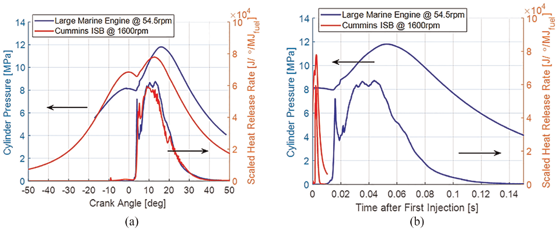
Comparison of cylinder pressure and AHRR for (blue) a large marine engine and (red) a 6.7 L Cummins ISB as a function of (a) crank angle space and (b) time after the first injection.
Figure 8 shows the normalized cumulative heat release as a function of time. The combustion process of a high-speed engine is completed in 0.01 s after initiating the first injection, but low-speed engines take 0.015 s to ignite the fuel. The combustion process for large-bore engines is longer by an order of magnitude compared with that of small-bore engines. These differences in the combustion timescales create potential opportunities and challenges for alternative fuels (i.e. chemistry solutions) to operate in wall-clock time.
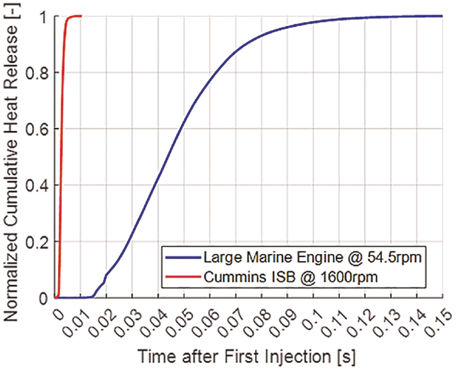
Normalized cumulative heat release as a function of time for a large marine engine and a Cummins ISB engine.
In addition to the challenges associated with combustion timescales, the physical size of large, two-stroke engines often makes experimental testing cost-prohibitive. Therefore, alternative fuel-based combustion system development and optimization present challenges. Simulating these engines is also computationally costly. With an increase in the engine cylinder’s physical size, the relevant turbulent flow features must be resolved to remain relatively constant. A computational cell count scales with the engine’s displacement for large engines. A small-bore Cummins ISB engine with a displacement of 1.1 L/cylinder and a large marine engine requires one million and hundreds of millions of computational cells, respectively. These numbers of cells make computational modeling of large marine engines unfeasible without large, world-class supercomputers. In addition to the computational challenges, scaling such large magnitudes in highly nonlinear (i.e. IC engines) systems is unexplored and, thus, presents uncertainty in the applicability of certain sub-models (e.g. fuel spray) in large-scale geometries. These aspects contribute to meeting the challenges of marine decarbonization efforts using new scaling techniques, artificial intelligence, and machine learning for accelerating design and small test engine platforms.
The efficiencies of large, ocean-going marine engines are incredibly high. Many current investigations of different LLCFs meet the demanding energy density range. The following section details the LLCFs, such as hydrogen, ammonia (NH3), methanol, dimethyl ether, LNG, and bio-derived and synthetic drop-in fuels. That section is followed by a section discussing air handling systems.
The potential of hydrogen as an IC engine fuel for marine applications
Hydrogen (in the form of H2) is a non-carbon-containing energy carrier in single- or dual-fuel IC engine applications. Hydrogen has a low volumetric energy density (requires at least 700 bar of pressure or liquefaction of H2 using the cryogenic technique) and a wide flammability limit with a low ignition energy. H2 presents significant challenges for the safe and effective operation as a fuel. Low energy density, high liquefaction cost, and the lack of large-scale global distribution infrastructure are significant obstacles to long-haul, heavy-duty transportation for hydrogen marine shipping applications.
The hydrogen production pathway used is often indicated by the “color of hydrogen.” 30 Most currently used hydrogen is “gray hydrogen,” which is sourced from NG; a pathway to produce “green” hydrogen is electrolysis by renewable electricity. Green hydrogen is a net-zero carbon fuel produced at approximately 75% efficiency and can be stored on-site. Combustion-enhancing properties of green hydrogen are also being explored. Hydrogen densification can be achieved by cooling of NH3, methanol, and more. The following section on NH3 also discusses the role of green hydrogen in producing more volumetrically energy-dense fuels. Hydrogen in IC engine applications such as marine, rail, and ground is necessary for long-term transitioning propulsion systems and includes hydrogen fuel cells. Build-out of hydrogen refueling can meet the infrastructure required for hydrogen fuel cells. More details on the role of hydrogen in future IC engines are covered in the editorial article by Onorati et al. 31 That article covers the main issues related to the availability and production of H2 and synthetic fuels (considering the potential to reduce carbon), involving economic considerations and its safe storage at the point of use. It also includes challenges, opportunities, and developments in H2 storage, injection technologies, combustion, and emissions control systems. 31 Blending with NG is another viable option for using hydrogen. Schultze et al. 32 analyzed the effect on power capability of the hydrogen concentration and lower heating value in the methane–hydrogen blend on power capability and CO2 emissions characteristics. Blending hydrogen by 20 vol % could significantly reduce CO2 emissions while maintaining the methane concentration at a moderate level.
Ammonia as a fuel for marine applications
Anhydrous NH3 is another alternative carbon-neutral fuel under consideration for marine applications. The liquefaction of NH3 can be achieved by compressing the gas to a few bar for storing and transportation. Long-haul or heavy-duty marine applications require high–energy density liquid NH3 fuels, and the global infrastructure for its transport is readily available. Ammonia is toxic and flammable and presents different storage and handling challenges from those described for hydrogen. Fuel system solutions for NH3 can be applied to first-fit and retrofit existing engines to accelerate IMO’s goals for reducing 50% of GHGs by 2050.
Green NH3 can be produced from green hydrogen with efficiencies up to 75%. 33 As one of the most dense hydrogen carriers, NH3 offers a pathway for significant GHG reductions. Additionally, NH3 is an input to fertilizer production (for a global commodity), a commercial refrigerant, and is often transported by rail and ship. Thus, fuel supply, storage, and transportation infrastructure at scale are already mature. Ammonia has been tested as a fuel with success and has challenges in spark-ignition and compression-ignition engines.34–36 The drawbacks of using NH3 as an engine fuel include high resistance to autoignition, high ignition energy, and low laminar flame speed (burning velocity), as shown in Figure 9. Although NH3 has a low energy content per unit mass compared with other liquid LLCFs, it has a volumetric advantage compared with hydrogen. Some studies NOx emissions.37,38
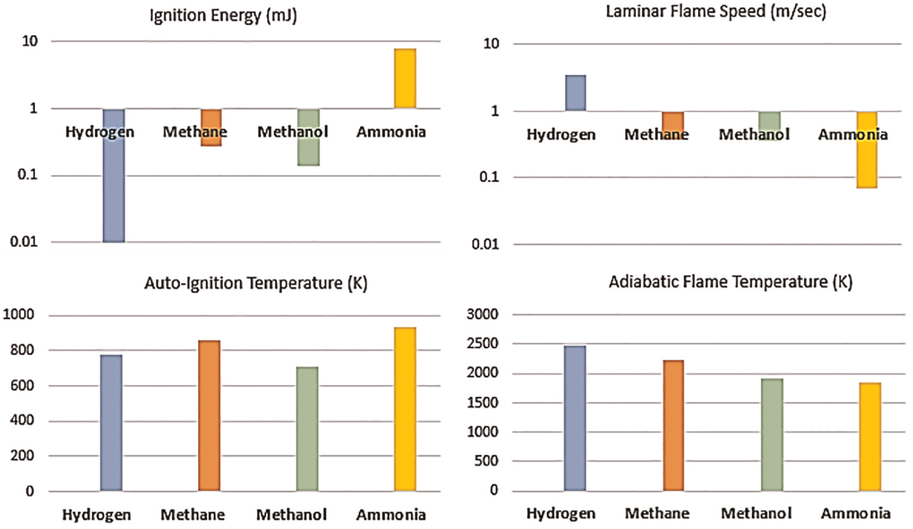
Fuel properties of some proposed alternative fuels compared using their ignition energy, autoignition temperature, laminar flame speed, and adiabatic flame temperature.
Similar to other low-cetane LLCFs, NH3 combustion in a compression-ignition engine involves a secondary high–cetane number fuel injection. Some ship engines are retrofitted to run on diesel–NG, in which diesel serves as the source of ignition. The same infrastructure can replace NG with NH3 with minor engine modifications. Dimethyl ether (DME) and NH3 have similar saturation pressures (∼8 bar) and are mixed in a high-pressure chamber. 36 The diesel engine is successfully operated with the injection of an NH3–DME mixture. Advanced injection systems can be designed to inject NH3 and the supporting fuel, which autoignites and initiates the combustion of NH3. Compression-ignition of NH3–diesel in a rapid compression expansion machine (RCM) 39 is facilitated and sustained by pilot-injected diesel flame and hot products.
Most international ship engines are large, low-speed, two-stroke compression-ignition engines and are unaffected by a slow-burning velocity of NH3 on the initiation of combustion. A large amount of NH3 injection into the engine can overcome the energy required to meet the engine torque. The use of modern SCR systems can consume the unburnt NH3 in the exhaust and resolve the problem of NOx emissions. Therefore, ship engines can use NH3 in single- and dual-fuel (e.g. MAN, WinGD, and Wärtsilä) engines within the next 2 years. The use of NH3 as a fuel for low-speed, two-stroke engines focuses on minimizing NOx and, in particular, N2O emissions. For high-speed, four-stroke engines, NH3–diesel combustion-initiation and duration improvements are necessary. The NH3 allows the engine to meet the total diesel power density in proportion to the gas-energy substitution ratio, while simultaneously reducing GHG emissions. If the NH3 fuel system fails, the diesel engine can fall back on operating on a diesel-only mode. The NH3–diesel RCCI combustion strategies are explored for small, four-stroke engines for high combustion efficiency. The reactivity difference between HFO or distillate diesel fuel oils and NH3 has a high research octane number (RON). Hence, diesel and NH3 RCCI and active combustion control (ACC) may become attractive options 40 to reduce GHGs; this ACC is equal to or greater than the NH3 substitution ratio when used with RCCI. Chiera et al. 41 demonstrated that NH3 substitution could reduce 80% of GHG emissions and, in controlled combustion with an appropriate NOx reduction catalyst, reduce NOx emissions. RCCI uses a high-reactivity fuel to control the ignition timing and combustion phasing. The NH3 is a low-reactivity fuel. Diesel and NH3 can be possible combinations of fuels for RCCI operation to achieve high efficiency and low emissions (Figure 10 and 11). 41
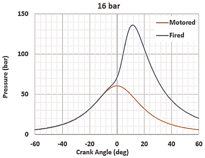
Cylinder pressure for NH3 RCCI combustion at 16 bar indicated mean effective pressure (IMEP).
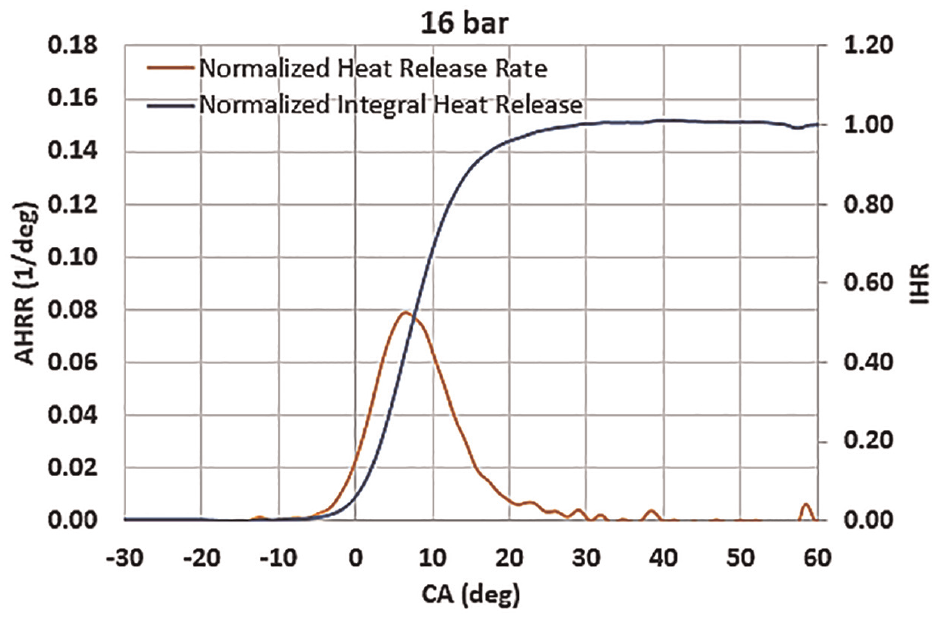
Heat release rate for 16 bar indicated mean effective pressure (IMEP).
An optically accessible test rig 39 under pressure-temperature and turbulence conditions similar to an IC engine has provided insights into relevant features of NH3–dodecane combustion in dual-fuel mode. The results were compared with methane–dodecane dual-fuel combustion under the same conditions. Optical investigations were accompanied by thermodynamic process analysis, and the fuel–air ratio was maintained between 1 and 2. The NH3 shows a long ignition delay, lower apparent (turbulent) flame speeds than methane, and high sensitivity to the start of injection (SOI) (i.e. too early SOIs result in lower fuel conversion rates). For the same SOI, a 50% mass burned fraction for NH3 is retarded by several CA degrees than methane. The pilot ignition delay in the ammonia mixture increases with the decrease in lambda (λ) from lean to stoichiometric conditions. Minimal pilot shares of dodecane in the total fuel mass (NH3 and methane mixtures) are between 0.8% and 2.2%, respectively, and these minimal shares were found to be reliable for the initiation of combustion under all investigated thermochemical conditions. The NH3 could be used in SCR or a catalytic converter42,43 for controlling high NOx and N2O emissions.
Methanol as fuel for marine diesel engine
Short-chain alcohols are of interest among alternative fuels owing to the matured production technology, available feedstock, and distribution infrastructure. The current compression-ignition engine fleet is not configured for methanol but shows potential for marine applications because of the abundant availability of raw material resources, ease of fuel storage, few modifications in existing engines, and low emissions. Methanol is a corrosive and low-calorific fuel, and its adaptation to ship engines needs to overcome technological challenges. Also essential are considered the raw resources/feedstocks ensuring their availability at a competitive price. Different production pathways for methanol use for marine engines are discussed for large-bore engines with few simulation results. A feasibility analysis and the practicality of methanol application in the marine transport sector are also reviewed. Methanol production from high-ash coal, municipal solid waste, and low-value agricultural biomass make it an attractive alternative to diesel.44,45 Numerous emerging markets (e.g. India, China) have access to large quantities of high-ash coal, which could be used in coal gasification to produce methanol.
Methanol production using carbon capture technology 46 provides a sustainable solution to fuel supply challenges by reducing the atmospheric CO2 concentration for commercial fuel production. Methanol production via atmospheric CO2 capture is in development. The high-octane number of methanol makes it favorable for powering spark-ignition (SI) engines and can also be used to power marine diesel engines. Methanol is an oxygenated fuel, with molecular oxygen amounts to half of the molecular mass of methanol. The presence of the OH− group accelerates the methanol separation when blending with hydrocarbon fuels. Modifying the fuel injection system and lines enables diesel engines to use methanol. As fuel evaporates, the intake charge cools significantly because of the high latent heat of vaporization and low stoichiometric air–fuel ratio. The effect of these factors on direct-injection engines is substantial.
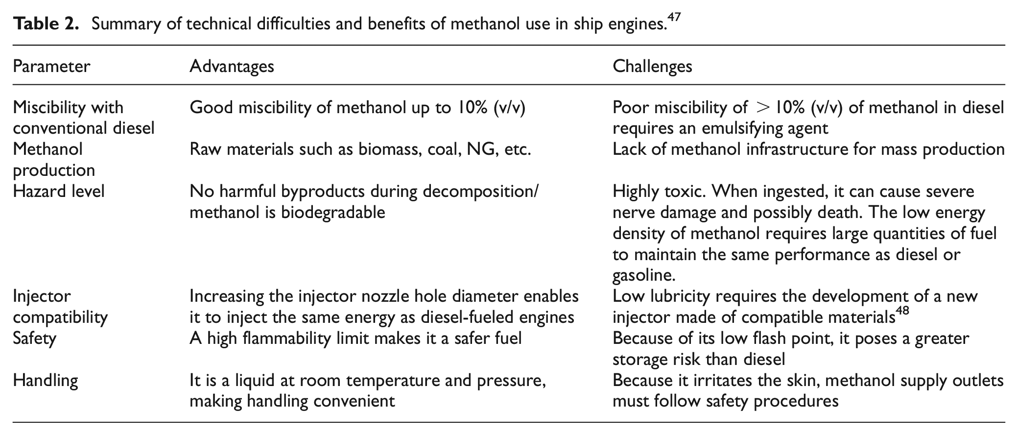
The energy density of methanol is approximately 20 MJ/kg (∼50% of diesel). Thus, the fuel injection system must be modified to accommodate an adequate fuel flow rate for obtaining the same power as a diesel-fueled engine. Methanol has low lubricity and viscosity, which could cause leaks in packings, gland seals, and fuel pump gaskets. Methanol-compatible polymers such as fluoroethylene propylene–perfluoroalkoxy sealing could resolve this problem. Table 2 summarizes the benefits of employing methanol in ship engines and possible technical difficulties.
Summary of technical difficulties and benefits of methanol use in ship engines. 47
Because of the new emission regulation set by IMO and increased globalization, marine industries are forced to find alternative fuels to meet the demand for low engine emissions. The use of methanol in diesel engines is challenging owing to its low calorific value and cetane number. Methanol can be used in diesel engines via port fuel injection and diesel by direct injection. 49 Methanol could be injected directly using different HPDI techniques into the engine combustion chamber with pilot diesel as an ignition source. The HPDI of methanol can be achieved using two separate injectors or a coaxial injector. Only one injector can deliver two different fuels at different injection timings in the latter. Further, intake port design and fuel–air mixing optimization are essential to enhance the performance of methanol engines.
Technological route for methanol use in four-stroke marine engines
Four-stroke marine engines in small vessels are similar to diesel locomotive engines used in railways. The low cetane number of methanol presents challenges for its direct use in diesel engines. Several techniques can be used to introduce methanol into large-bore marine diesel engines, including (i) blending, 50 (ii) emulsification with diesel, (iii) port injection of methanol 51 and direct injection of pilot diesel, 52 (iv) HPDI of methanol,53–55 and (v) the glow plug concept.
The HPDI technique can be implemented in two ways: injecting diesel and methanol separately using different injectors or injecting both fuels simultaneously with a special coaxial injector. These injection techniques can alter the performance of the compression-ignition (CI) engines. 56 All other injection techniques are mentioned in detail in the literature 47 ; in the context of large-bore marine engines, an essential HPDI technique is discussed in the present editorial. Without compromising the overall engine performance, the HPDI technique displaces a maximum amount of diesel with methanol and reduces exhaust emissions. During the compression stroke, the HPDI technique injects methanol into the combustion chamber and forms a non-premixed mixture, and ignition starts with the pilot injection of diesel near top dead center (TDC).
HPDI with methanol using two separate injectors
Two different injectors can be used to facilitate the direct injection of methanol and diesel (the pilot to initiate the combustion) as the primary and secondary fuels, respectively. Figure 12 illustrates the layout of an HPDI-controlled, methanol-fueled, 16-cylinder, large-bore marine engine with two independent injectors. Methanol combustion with 5% pilot-injected diesel improves the thermal efficiency and emission characteristics. 47 An electronic fuel injection system is needed to improve the performance of existing marine diesel engines operated with mechanical fuel injection systems. Large-bore engines benefit from electronic fuel injection systems to meet strict emission norms by optimizing various injection parameters concerning varying loads and speeds. 58
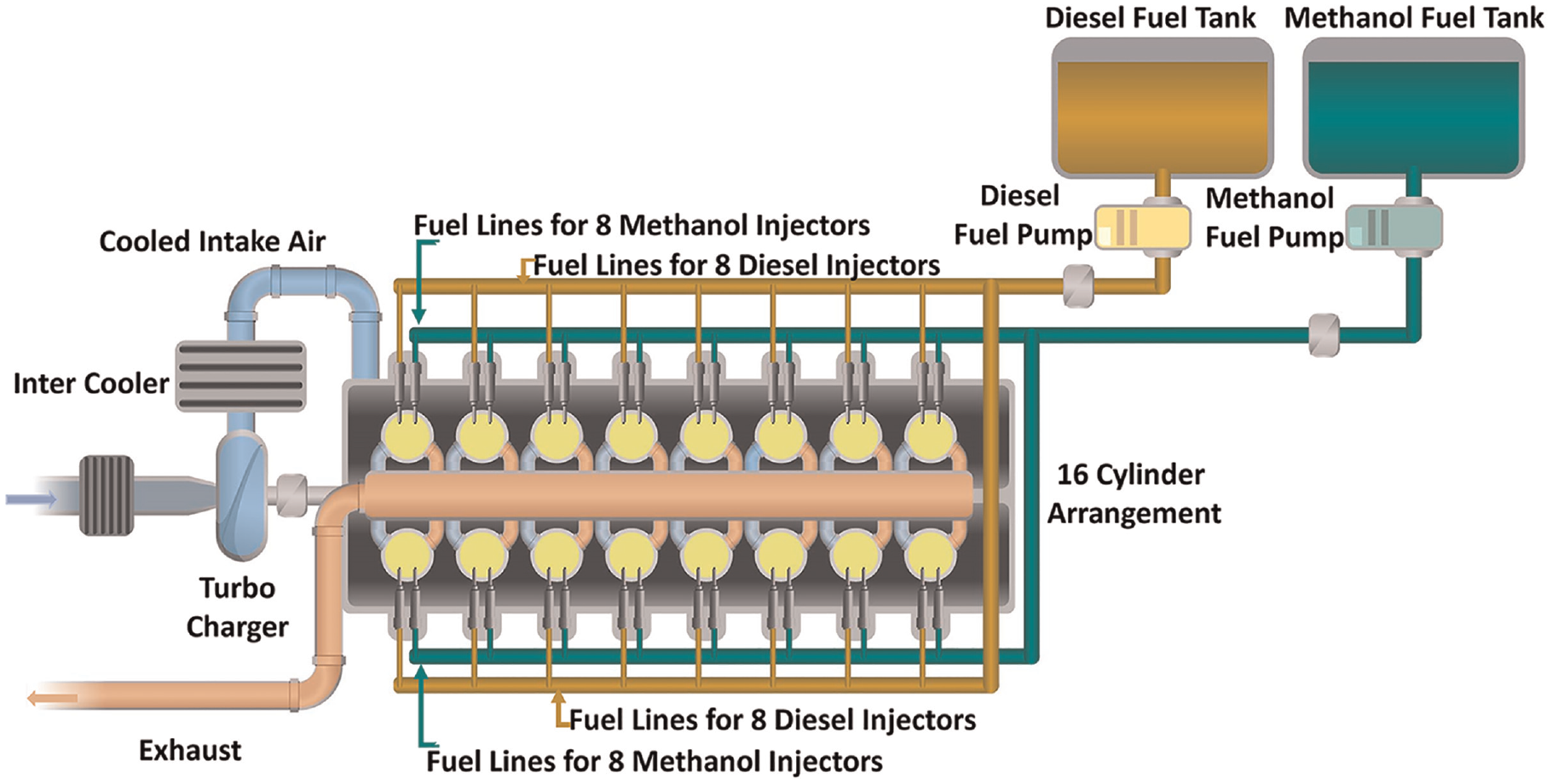
Schematic of HPDI technique using two separate injectors for large-bore marine diesel engine.
The HPDI technique requires additional cost and space in the cylinder head to accommodate two fuel injectors, which provide great flexibility in changing the fuel injection timing and duration to meet the operational requirements. It ensures superior mixing and the combustion of methanol with pilot-injected diesel. Wang et al. 53 studied the methanol–diesel spray interactions in a constant-volume combustion chamber (CVCC). They concluded that methanol direct injection and pilot-injected diesel achieve low emissions and combustion efficiencies similar to diesel.
HPDI using a co-axial injector
A new “co-axial injector” concept could offer a viable solution to fit the two injectors in compact cylinder heads. The co-axial injector accomplishes dual-fuel capability in a single injector body without modifying the cylinder head. The coaxial injector has two fuel lines for simultaneously delivering two fuels and enables overlapping fuel injections, if needed. Figure 13 shows a coaxial (methanol-fueled), injector-operated, large-bore marine engine demonstrated by Wärtsilä. Methanol has a smaller volumetric heat content than diesel and requires a large-hole diameter injector to supply high fuel injection quantity. For heavy-duty engines, the coaxial injector design allows the feasibility of multiple alternative fuels.
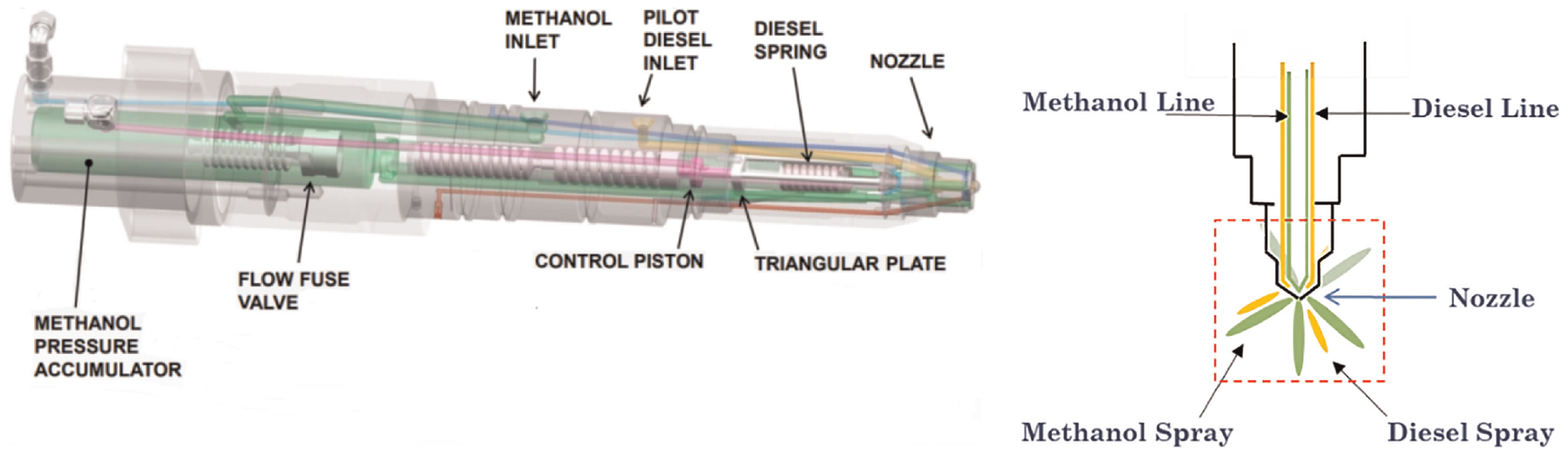
Coaxial injector for large-bore marine engine. 72
Using a unique coaxial injector concept, 72 Wärtsilä converted a sizeable seagoing passenger ferry called the Stena Germanica. Fuel injection pressure was crucial in this concept. The fuel injection pressures for methanol and diesel were maintained at 600 and 1300 bar, respectively. The coaxial injector approach exhibited no knocking and engine derating; low total hydrocarbon (THC), CO, and formaldehyde emissions but had high NOx emissions – and a cost-effective adaption of methanol. NOx depend on the injection of the pilot fuel quantity and can be reduced by optimization.
Feasibility of methanol using HPDI technique for four-stroke marine diesel engines
A coaxial injector is an attractive solution for large-bore marine diesel engines. Initial investigations of combustion, performance, and emission characteristics are necessary for each engine category, either experimentally or computationally. Experiments require many resources to develop an expensive setup. They are time-consuming; however, the computational study offers a flexible and efficient prediction of engine performance parameters and considers the time and cost of operation. Experiments are required to finalize the conceptual design and dimensions optimized by the simulation studies. 1D or 3D deterministic approaches can be used for engine simulations. The 1D approach is a simple deterministic approach. It considers parametric variation in a single direction with respect to time, and the 3D modeling approach felicitates the temporal and spatial variation of mixing and combustion processes. 58
Case study of direct injection of methanol (HPDI technique) for four-stroke marine diesel engine using simulations approach
Using a simulation approach, Kumar et al. 55 investigated the feasibility of methanol for a 16-cylinder, large-bore diesel engine (used in marine and locomotive sectors). For 1D model testing, commercial GT Power software was used and validated using the experimental data of the locomotive diesel engine. Using co-axial injection, methanol was introduced into the cylinder. Large-bore diesel engines worked on different notches, simulating engine loads and speeds. Figures 14(A) and 15(A) show the base model validation at different notches. The model predicted the engine performance parameters at various speeds and was tuned for methanol. The highest difference in the in-cylinder pressures from the experiments and simulations was observed at the seventh notch. A heat release rate (HRR) at different notches was essential for validating the 1D model. The model accurately predicted the heat released during combustion. The experimental and numerical HRR simulation results showed a similar shape, with minor deviation due to heat losses in the experiments and assumptions in the computational model. Figure 14(A) also presents the NOx emission validation for the base model at high engine notches and shows a significant difference at low engine loads because of the model’s limitations.
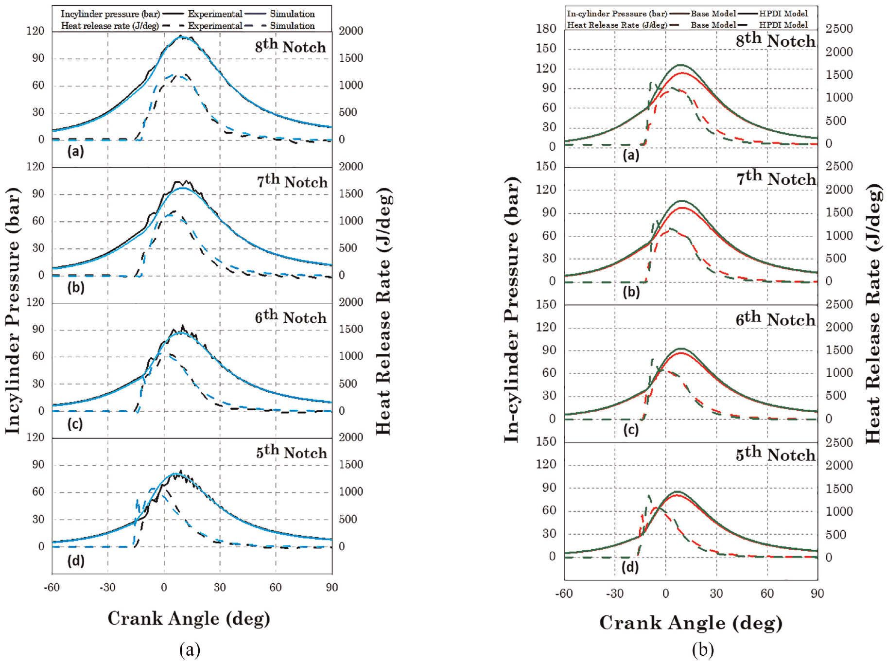
In-cylinder pressure and HRR for (A) base model validation and (B) HPDI model comparison for (a) eighth notch: 1050 rpm, (b) seventh notch: 950 rpm, (c) sixth notch: 850 rpm, and (d) fifth notch: 750 rpm. 55
The 1D model limits the prediction of THC and CO emissions. The model was first validated with diesel before implementing methanol direct injection and pilot-injected diesel. The methanol burn rate was predicted using three-pressure analysis (TPA) and a measured + predicted (M + D) model. The TPA model used pressure at three locations (intake, cylinder, and exhaust) to predict the burn rate. With the input from the TPA model and experimental results, pulse calibration was performed via the M + D model. The base model used for methanol injection displaced 90% of diesel on an energy basis using methanol in the original model and 10% of diesel as the ignition source. However, the nozzle configuration (hole dimension and the number of holes) must be optimized. The injected methanol quantity should be twice the diesel quantity to develop a similar power. The base model has nine holes of 0.35 mm in diameter. After multiple iterations for methanol injection with pilot diesel, the optimized number of holes for methanol and pilot diesel emerged as five (ϕ = 0.54 mm) and three (ϕ = 0.486 mm), respectively. Figures 14(B) and 15(B) compare the base and HPDI models (methanol with pilot diesel). The HPDI model predicts a higher in-cylinder pressure than diesel fueling at different notches.
Figure 14(B) shows that the HRR for the HPDI model is slightly higher than that of the base model (only diesel fueling). Methanol is an oxygenated fuel and contributes to superior combustion. The injection strategies (i.e. injection pressure and timing) are optimized with respect to time. 59 The base model for methanol introduction helps to improve the performance. Figure 15(B) shows high brake thermal efficiency, torque, and maximum in-cylinder pressure, as well as low NOx emissions for the HPDI model compared with that of the base diesel model. Methanol has a high latent heat of vaporization, which decreases the NOx emissions due to a low in-cylinder temperature.42,60 The LEC GmbH and their partners in the EU Horizon 2020 project HyMethShip61–65 developed a carbon emission–free combustion system using methanol. The HyMethShip system (Figure 16) uses heat from exhaust gases to reform methanol into hydrogen for combustion in a reciprocating engine. This concept uses precombustion carbon capture via membrane separation in a membrane reformer to drastically reduce CO2 emissions. The concept is feasible for spark-ignition and diesel–hydrogen dual-fuel combustion.
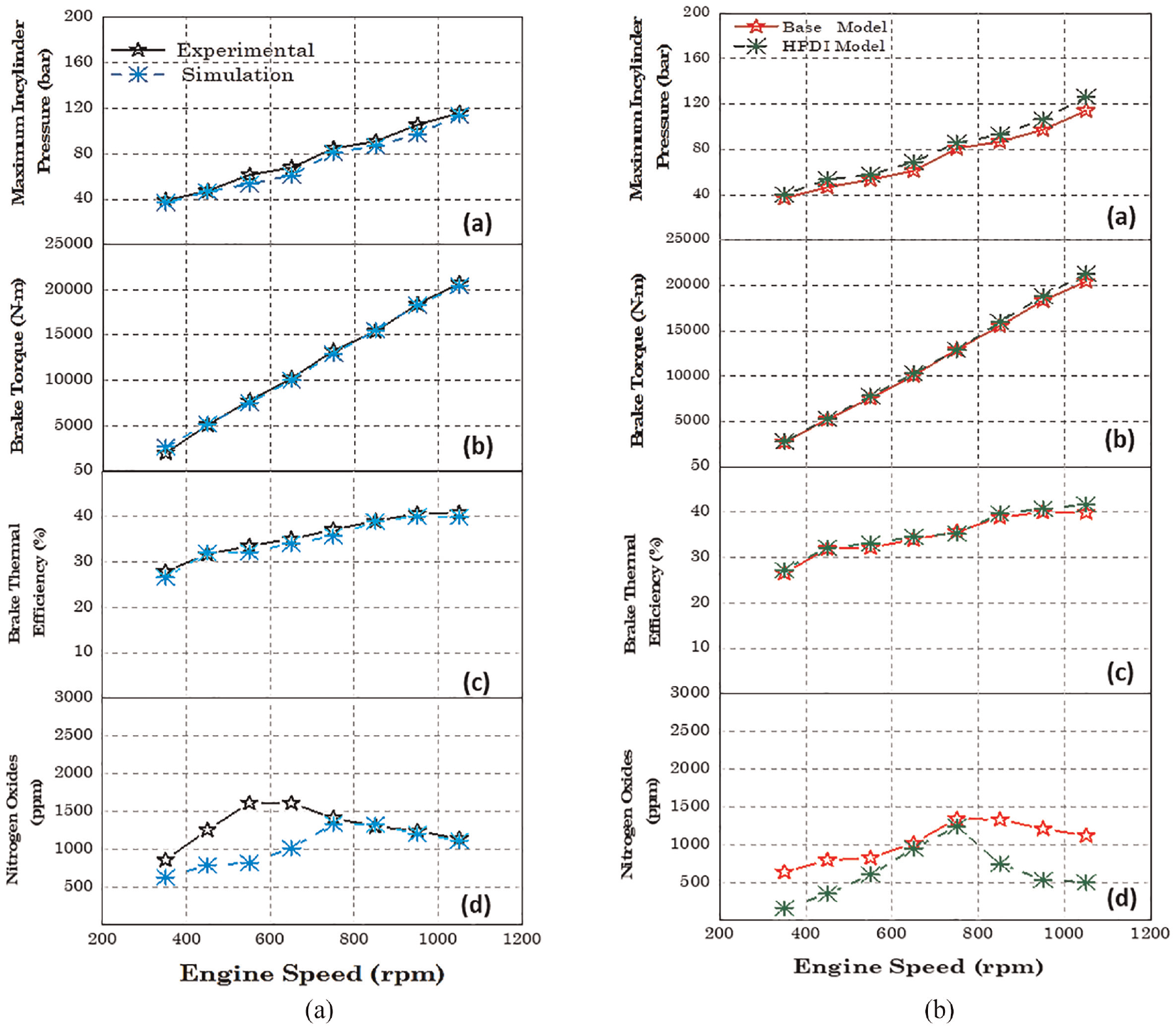
Performance and emission parameter variation at different notches of (A) base model validation and (B) HPDI model comparison for (a) maximum in-cylinder pressure versus engine speed, (b) brake torque versus engine speed (rpm), (c) brake thermal efficiency versus engine speed, and (d) NOx versus engine speed. 55
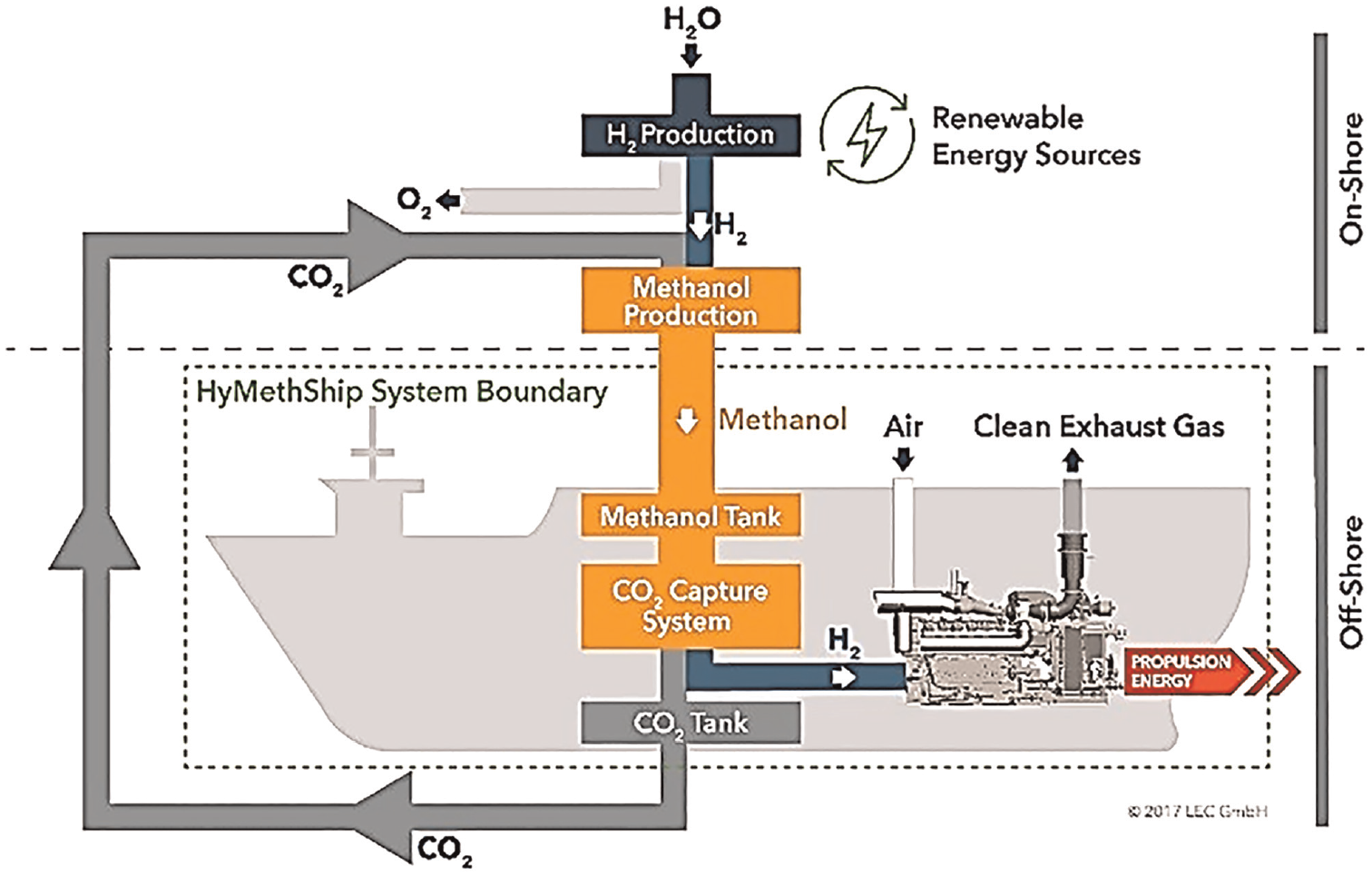
HyMethShip concept. 61
No vessel operates based on precombustion carbon capture, but membrane reformers for hydrogen production are under consideration. 66 The LEC ENERsim tool was used to assess the HyMethShip concept for an RoPax ferry operating in the Baltic Sea. 66 The baseline HyMethShip concept was compared to an optimized concept that uses a boiler for supplementary heating for the methanol reformation. Both concepts were compared to a propulsion concept using renewable methanol in the engine.
Figure 17(a) shows the annual cost of all concepts broken down by different contributors, including capital expenditure (CAPEX) investments, operating expenses (OPEX) and fuel costs. Downward arrows indicate the cost savings from CO2 recycling. As shown in Figure 17, the HyMethShip basic concept (concept 2) has lower total costs than the “Re-MeOH” concept (concept 1) because of the cost savings from CO2 recycling. Concept 3 achieves even lower total costs than concept 2 because higher CO2 cost savings are generated by the high CO2 capture rate. The CO2 capture rates correlated directly with CO2 cost savings and are shown in Figure 17(b). The optimized operation with the additional heat source in concept 3 results in a high CO2 capture rate of 92.1%, which is close to the imposed technological maximum of 95%. The results show the investigated case of a ferry, and the HyMethShip concept has clear economic advantages over the Re-MeOH concept as an energy carrier.
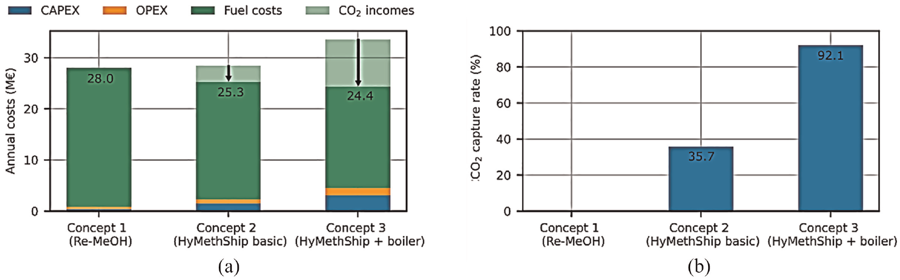
Performance comparison of the three studied system concepts. Panel (a) shows the total annual costs and contributions of CAPEX, OPEX, fuel costs, and cost savings from captured CO2. Panel (b) shows achieved CO2 capture rates. 66
In a joint research program, OMT Officine Meccaniche Torino S.p.A (OMT) and LEC GmbH are investigating the potential of high-pressure direct injection of NH3 and methanol for medium-speed engines. 67 The OMT injector (Figure 18, left) is designed and developed for 1300 bar fuel injection pressure and robustness against cavitation erosion. The engine investigations are carried out on a medium-speed, four-stroke, single-cylinder research engine. The OMT injector for NH3 and methanol is centrally mounted in the combustion chamber. A diesel pilot injector is installed in a lateral position, featuring a unique spray hole configuration. An illustration of the fuel jet interaction of the diesel spray and the methanol/NH3 spray is shown in Figure 18 (right).
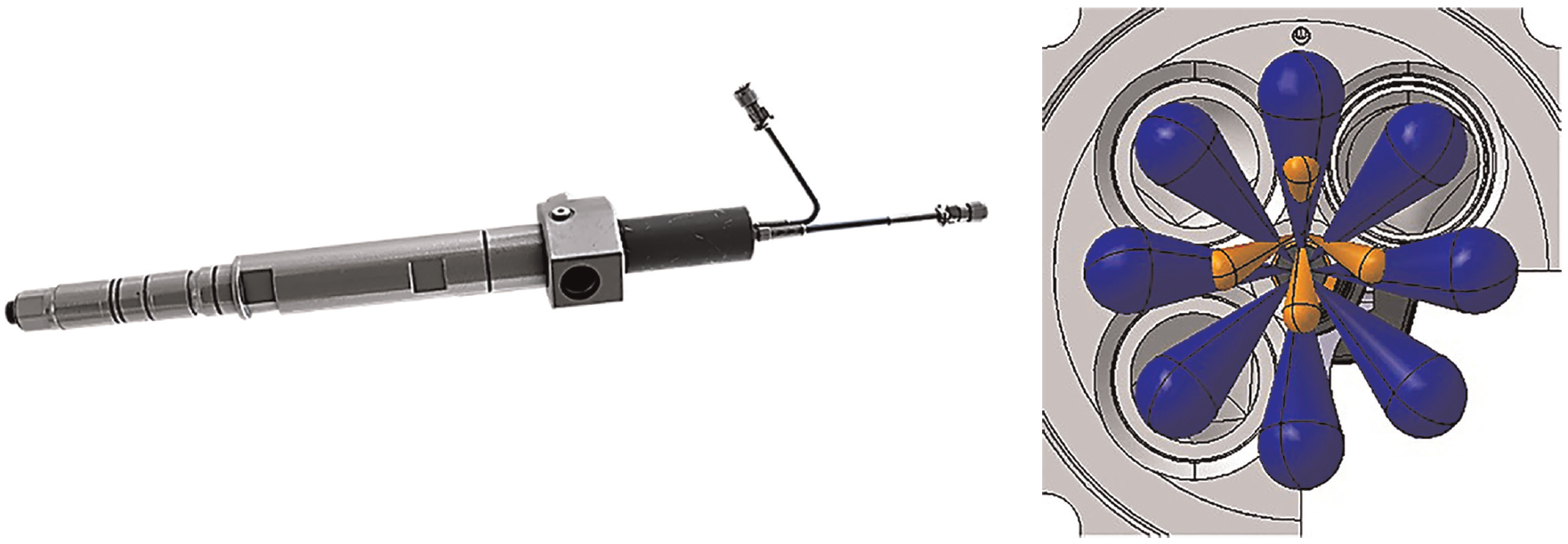
(Left) OMT injector for renewable fuels and (right) (orange) illustration of diesel pilot and (blue) methanol/NH3 fuel jet interaction. 67
The effect of dwell timing on heat release for a diesel–methanol operating condition with a 10% fraction of diesel is shown in Figure 19. An increase of the dwell time beyond 4 CA degrees results in a slightly earlier start of combustion (SOC) and shows an insignificant difference in the main part of the heat release.
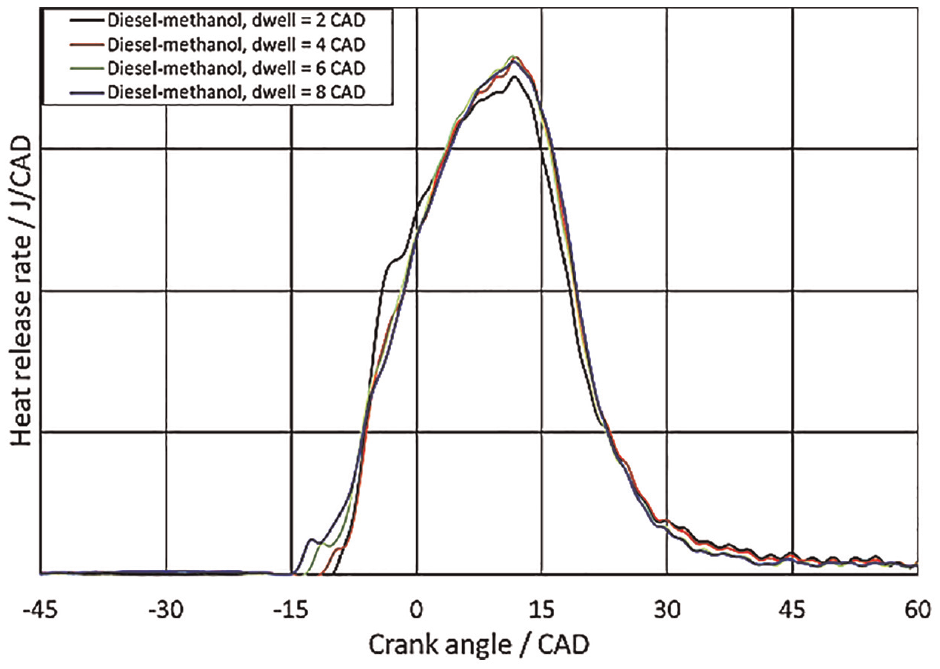
HRR for diesel–methanol operation at 20 bar brake mean effective pressure (BMEP) at 750 rpm with dwell time between 2 and 8 CA degrees. 67
DME for marine applications
Methanol can be produced from various biological or synthetic pathways. Methanol is also a precursor to other synthetic fuels, such as DME, and can be directly used in compression ignition engines. DME can be produced from coal, NG, biomass, or combinations of feedstocks. DME can be produced from methanol dehydration in a two-step process or directly from syngas (i.e. CO and H2). The production of DME is summarized by Boehman. 24 DME has a high cetane number, is stored as a liquified fuel, and shows a low sooting tendency because of the lack of a C–C bond contrary to Diesel. 68 DME can be blended with diesel fuel up to 30% by volume. The short ignition delay of DME results from the lower bond energy of C–O compared with that of C–H, which also contributes to further reducing PM emissions.
Challenges
DME production and distribution infrastructure is currently limited around the world. DME shows high compressibility and lower lubricity, density, and viscosity than mineral diesel. The compression work of a DME pump is higher than that required for mineral diesel fuel owing to the DME’s high compressibility and low density. DME offers challenges with fuel injection equipment because of the corrosion of vital fuel injection equipment and engine parts, including plungers and the fuel feed pump. 69 Fuel injection equipment, storage, and delivery systems require hardware and software modifications because of these challenges with using DME.
LNG as a low–GHG emissions fuel for long-haul/heavy-duty marine
With well-established infrastructure and production systems and a small cost of retrofitting, LNG-fueled marine engines can be developed. LNG can replace the HFO and diesel-fueled engines by maintaining low GHG emissions and keeping performance similar to base diesel engines. Based on fuel chemistry and energy-specific CO2 emissions, an efficient LNG-fueled CI engine is developed with the potential to reduce GHG emissions by 25% (no methane slip). Biomethane from organic waste and biomass offers further reductions in carbon intensity and proliferates in International Energy Agency (IEA) scenarios. Biomethane allow countries to reduce emissions in hard-to-abate sectors, including marine freight transport. Mostly bio-derived methane is used in power and heat generation applications. 70 However, controlling methane slip is challenging with LNG-fueled engines.
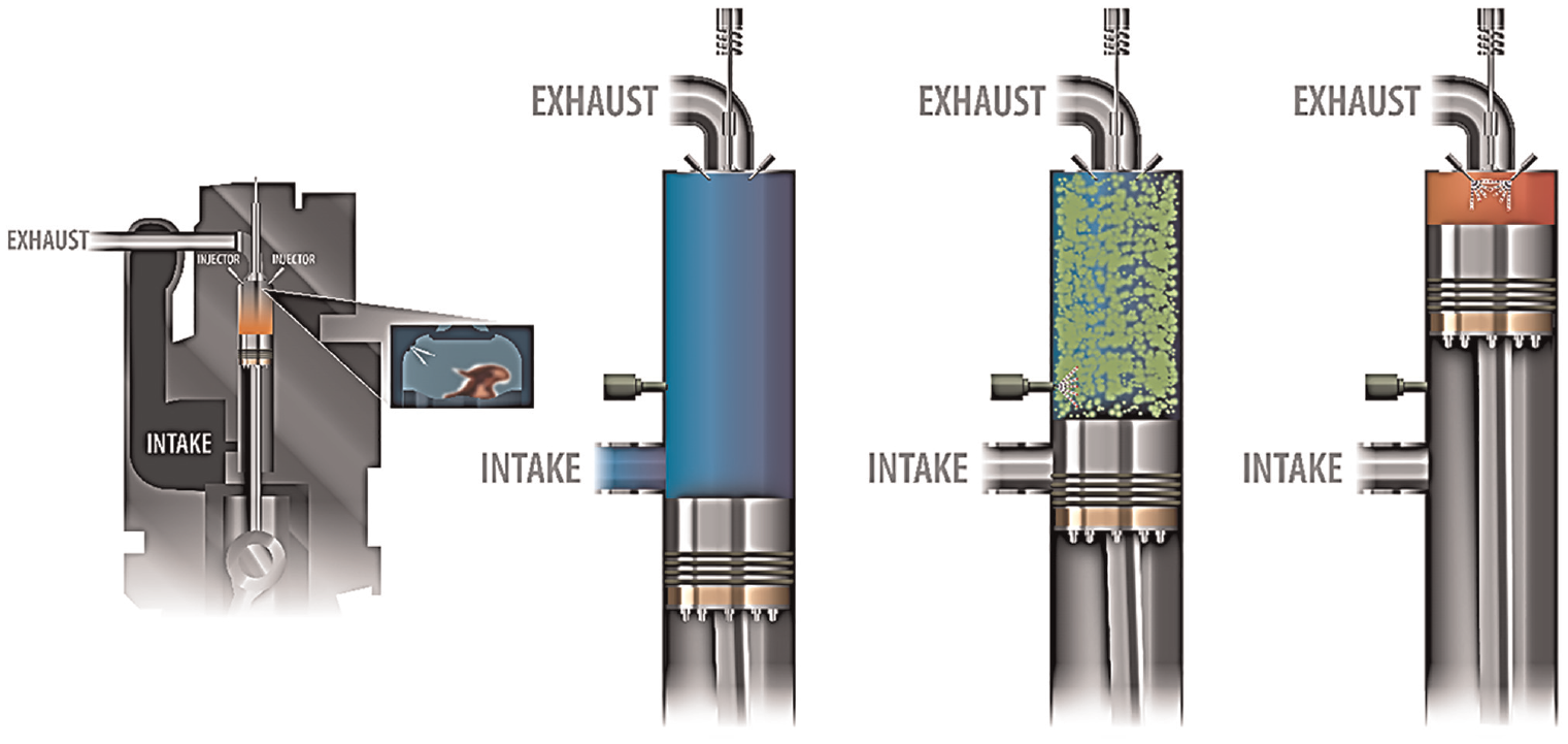
Because of the promising benefits of LNG, several marine diesel engines are outfitted as dual-fuel engines, as shown in Figure 20, and are robust for LNG-capable ships up to the next one or two decades. The LNG-converted propulsion system consists of an LNG tank, a liquid-to-gas vaporizer, a pressure regulator with a low-pressure port gas admission valve (GAV), a diesel pilot injector, and a reduced compression ratio engine. The gas substitution ratio is often a port-injected 95% NG and 5% pilot-injected diesel.
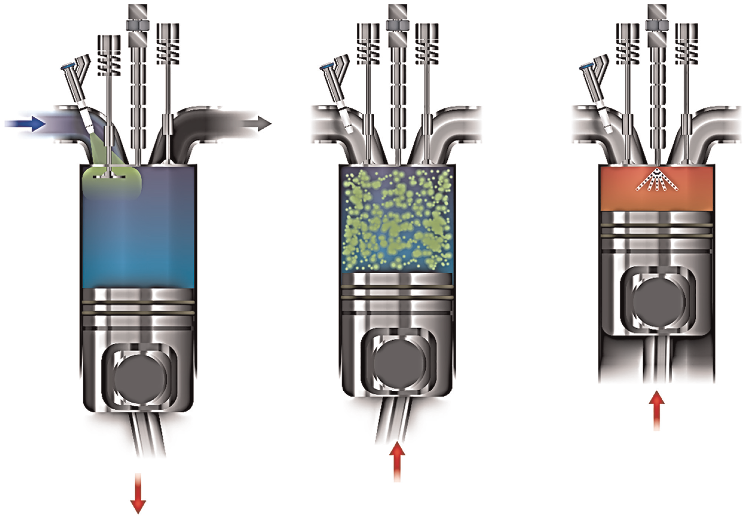
Illustration of conventional dual-fuel configuration: (green) LNG and (red) diesel in (blue) the air; adapted from Jääskeläinen. 71
This section focuses on implementing low-pressure, dual-fuel systems for two-stroke engines, as shown in Figure 21. The engine can run on HFO or diesel oil and allows switching to dual-fuel mode operation. The main diesel injectors are turned off during LNG dual-fuel operation. After closing the exhaust valve, the port GAVs are opened during the intake stroke to avoid the direct short-circuiting of NG during the valve overlap period. Before the end of the intake stroke, the port GAVs are closed so that a portion of the intake air charge purges fuel in the intake ports.
Dual-fuel with two-stroke engines. (green) LNG and (red) diesel in (blue) the air.
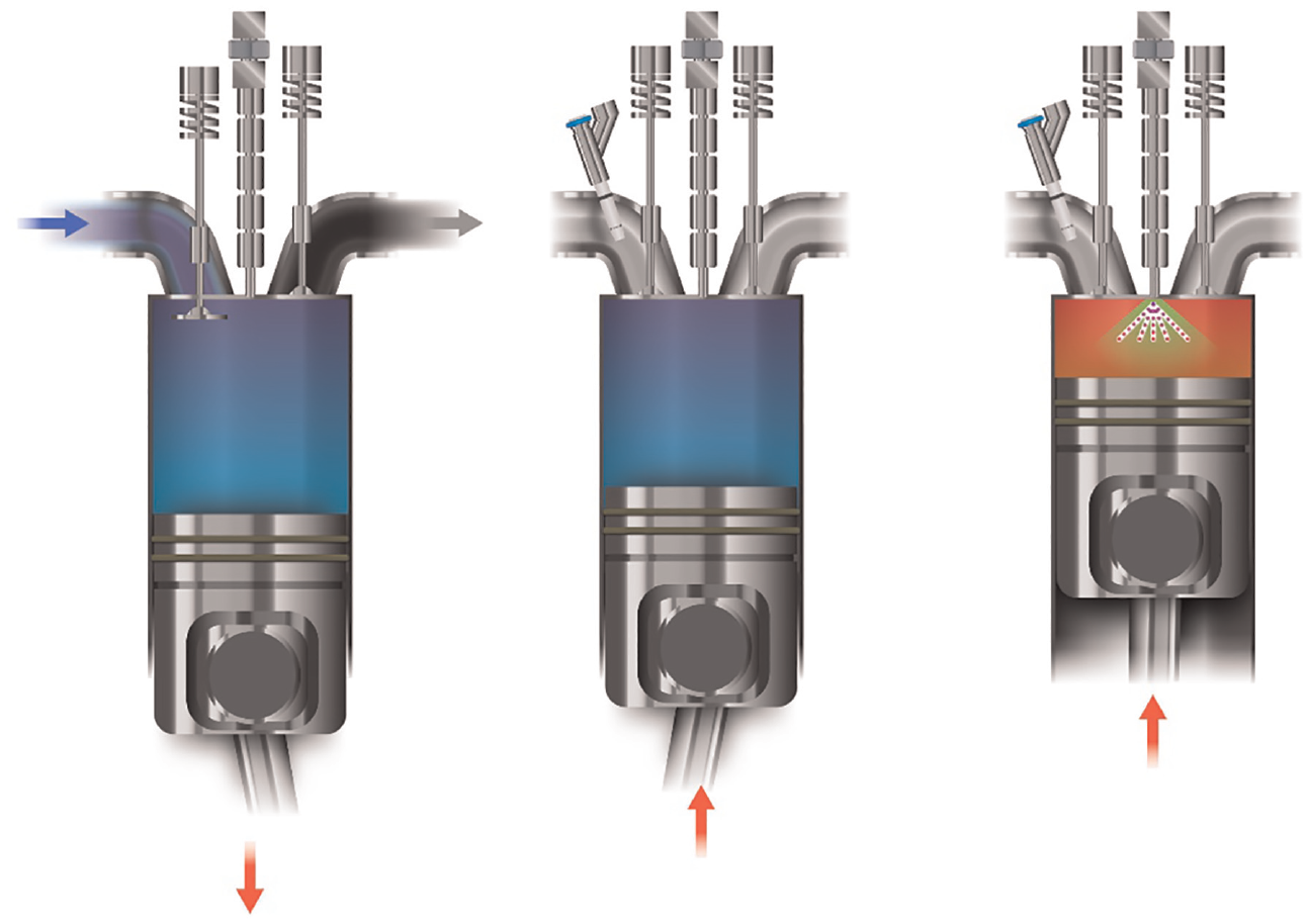
Inside the cylinder, NG and air mixing occur, and ignition starts near TDC by the pilot-injected diesel (around 5% of the total energy) in each cycle. Figure 22 shows the small pilot ignition region in the conventional dual-fuel (CDF) mode of operation. The combustion process shares fundamental elements of premixed and spark-ignited flame front propagation. The pilot-injected diesel achieves the spark function (without a spark plug) because large diesel engines generally use quiescent combustion chambers and rely on high turbulence generated by diesel spray. The LNG flame speed is relatively low because less turbulence is generated by pilot-injected diesel in LNG mode. The lean-operated diesel engine slows the flame speed and minimizes NOx emissions.
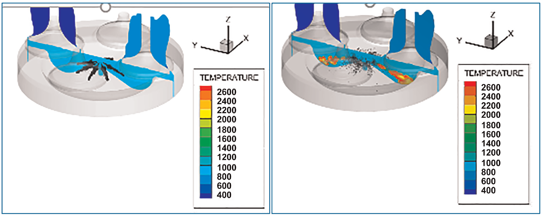
Conventional dual-fuel, showing (left, prior to ignition) injection quantity and (right, just at the ignition point) ignition of 4% pilot diesel. The engine modeled is a 170 mm bore operating at 10 bar indicated mean effective pressure (IMEP) at 1500 rpm.
Methane slip
The lean mixture, low compression ratio, small penetration and low induced turbulence all contribute to methane slip and a loss of efficiency potential. 72 During the compression and combustion (first part of the pressure rise) phase, premixed methane is pushed into the crevice regions (a gap between the piston top ring and liner). The slow propagating flame cannot reach the crevice regions due to slow flame propagation, low temperature, and turbulence in the combustion chamber, which contributes to unburned methane (in the exhaust), or methane slip. Methane is 28–30 times more potent as a GHG than CO2, so even small quantities of methane slip can seriously erode the GHG benefits of diesel-to-LNG conversion. At part load, methane slip in CDF (LNG) engines is as high as 15 g/kWh. 73 Figure 23 shows that methane slip must be less than 5 g/kWh to maintain a net-positive GHG reduction. For achieving the full potential of LNG-fueled engines, substitution of diesel fuel to natural gas at the same efficiency and zero methane slip, can GHG emissions can be reduced by 25%. If methane slip is maintained less than 1 g/kWh, then the GHG reduction achieved is 20% 74 – which can be recovered by the efficiency benefits of higher combustion efficiency as seen in Figure 23.
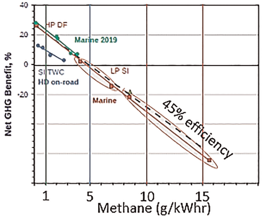
Effect of methane slip on net GHG benefit relative to 45% efficient diesel. 71
Methods to reduce methane slip
According to Hiltner et al., 74 methane slip originates by three primary and one secondary mechanisms: (1) direct short-circuiting, (2) crevice region quench, (3) bulk quench, and (4) catalytic after treatment. The use of SOGAV solenoid valves can minimize the direct short-circuiting between the opening (after closing the exhaust valve) and closing (before the intake valve opening) of the engine intake process approximately 120 CA degrees. Crevice region quenching can be reduced by (a) decreasing the gap volume between the piston top ring and liner, (b) decreasing the methane concentration in the crevice region (by fuel stratification), and (c) burning methane in the crevice region. A short burn duration closer to TDC (<20 ATDC) avoids bulk quenching. Combustion later than 20 ATDC affects bulk quenching (at low temperatures and turbulence) and leads to decreased combustion efficiency. For converting unburned methane to CO2 and H2O, a clean-up catalyst can be installed in the exhaust system. A marked difference exists between the capability and availability of a lean burn aftertreatment system and a stoichiometry.
Low methane slip methods can be achieved by avoiding short-circuiting and premixed methane in the crevice regions (burn duration <20 CA degrees), moving up the top piston ring, and cleaning the unburned methane using a catalyst. The following section describes three methods for minimizing methane slip and improving diesel-like efficiency.
High-pressure dual fuel injection
NG is pressurized between 300 and 500 bar and injected via a dual-channel diesel injector, as shown in Figure 24. Diesel fuel is injected first to start the ignition, followed by NG injection at a high compression ratio similar to diesel, and both fuels burn in a diffusion/diesel-like flame (Figure 25, Woodward L’Orange high-pressure dual fuel [HPDF] injector). In this case, only air goes into the crevice regions (no premixing), and the methane is contained only in the diffusion flame. A fast burn duration avoids bulk quenching, and the methane slip is relatively low (<1 g/kWh). The dual-fuel injector can be installed similar to a conventional diesel injector, while the liquefaction of NG (using a cryogenic pump at 500 bar and 112 K) is challenging.
High-pressure, dual-fuel combustion process. (blue) Air is compressed, (dashed-red) high-pressure direct injection of pilot diesel fuel followed closely by a high pressure direct injection of NG, adapted from Jääskeläinen. 71

Woodward HPDF–LNG/diesel dual-fuel injector.
Reactivity-controlled compression-ignition with active combustion control
RCCI concepts fueled by gasoline–diesel 75 and NG–diesel57,76 was demonstrated on a 1.9 L passenger CI engine. Chiera et al.77,78 used the high-speed diesel engine (170 mm bore) with the same fuel equipment as the CDF (LNG + vaporizer + port-admitted gas + pilot-injected diesel). Enabling early diesel injection timing and active combustion control (ACC) provides high efficiency, low methane slip, and control over NOx emissions. This seeded premixed combustion achieves methane slip reduction with a short burn duration (triggers a distributed/volumetric autoignition) and enhances combustion near the crevice region. ACC adjusts the cycle-to-cycle autoignition and combustion phasing for obtaining an optimal center-of-combustion and controlled RCCI.
Figure 26 (left) shows the high peak HRR of RCCI relative to conventional diesel combustion (CDC) and conventional dual fuel (CDF), and Figure 26 (right) quantifies the short burn duration. Figure 27 (left) shows the net GHG reduction potential of NG–RCCI combustion relative to diesel, showing modest gains at low loads and a net of as high as 28% reduction at mid- and high loads. Figure 27 (right) shows the net improvement in methane slip as a percentage of total methane admitted.
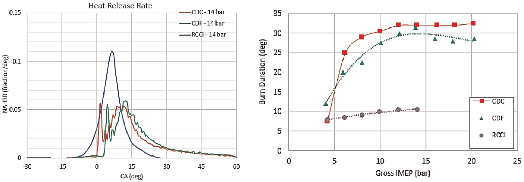
(Left) HRRs for conventional diesel combustion, conventional dual fuel combustion, and RCCI dual fuel combustion. (Right) 10°–90°CA burn durations for CDC, CDF, and RCCI combustion over a range of gross indicated mean effective pressure (IMEP). 77
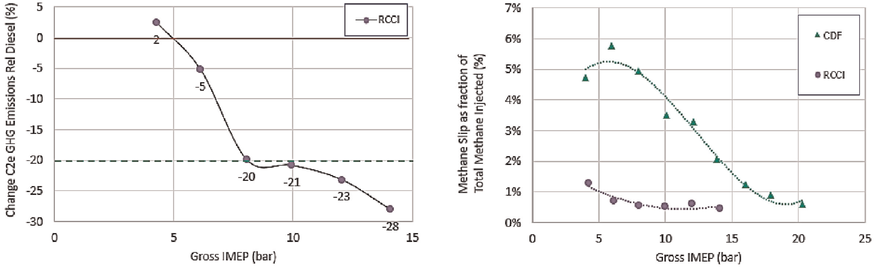
(Left) Net GHG emissions reduction for NG–RCCI combustion relative to CDF. (Right) Methane slip as a percentage of methane injected. 77
Previously, studies have shown lower emissions, efficiency, and power density than diesel under premixed-stoichiometric combustion.79,80 However, with controlled end-gas autoignition (CEGAI) enabled by ACC, fast combustion of natural gas, even with high EGR percentage, enables short burn duration and good combustion phasing, thus achieving high brake thermal efficiency and power density similar to that of diesel engines. 77 Emissions out of a three-way catalyst (TWC) are low enough to achieve Euro6/China6 emissions standards and have the potential to meet the expected targets of Euro7 and California emissions standards. With a TWC, engine-out methane emissions can be well-oxidized and reduced to minimum levels below 1 g/kWh. ACC and CEGAI can increase efficiency by improving in-cylinder methane combustion – thus reducing methane slip - through combustion, EGR, and spark timing control. Actively controlled, flame-triggered autoignition (FTAI) achieves a short burn duration and optimal combustion in which the first half of fuel burns in a propagating flame and spontaneously burns the remaining fuel, as shown in Figure 28, which shows that under FTAI at the 50% mass fraction burned (MFB) point, the heat release rate nearly doubles – which is evidence of volumetric ignition of the remaining fuel in a single non-knocking combustion event. This places the rapid pressure rise and peak pressure after TDC (i.e. avoids overpressure) without knocking (i.e. ringing).
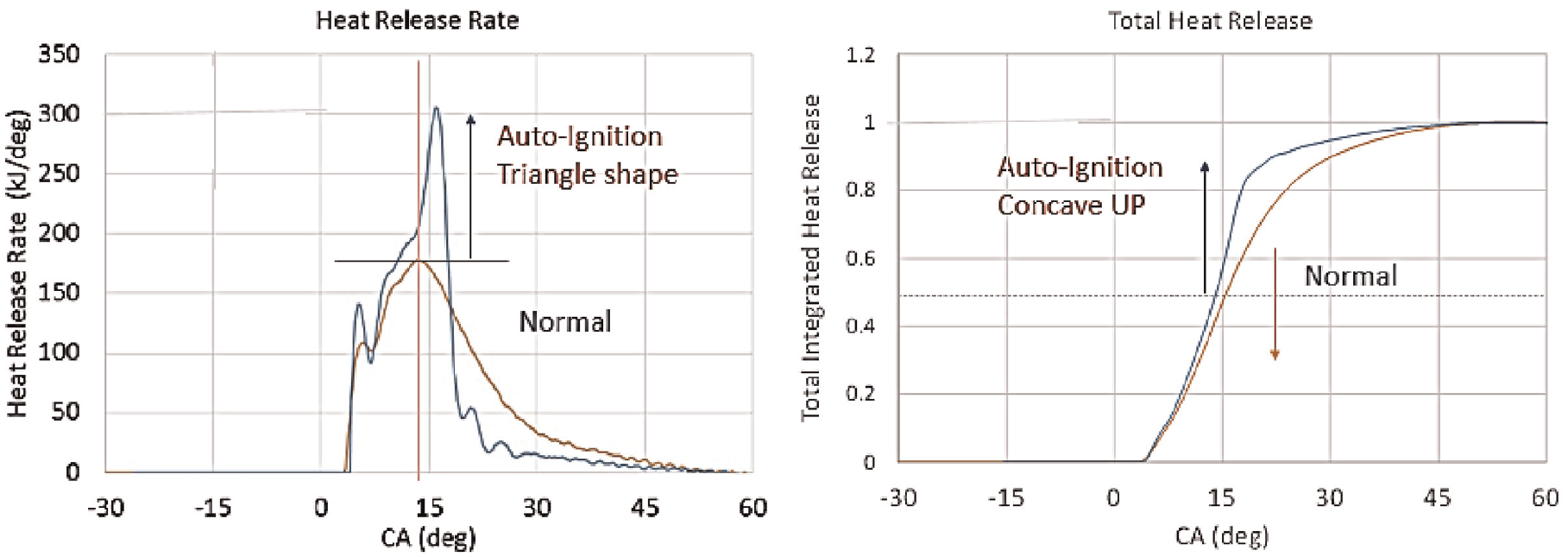
Flame-triggered autoignition. (Left) HRR shows (blue) flame-triggered autoignition has a similar HRR until approximately 50% MFB, and then the HRR nearly doubles after 50% MFB, burning the remaining fuel in an autoignition burst. (Right) Cumulative heat release.
The technology and infrastructure for LNG fueling systems are matured for developing new engines and retrofitting existing engines. LNG is essential for transitioning to zero-carbon fuels such as NH3 and hydrogen. LNG conversions lack the use of their full potential owing to unacceptable levels of high methane slip. HPDF, RCCI, and Stoic-EGR-TWC methods can reduce methane slip to enable LNG ships and mitigate the adverse effects of obtaining GHG reduction (Methane Slip <1 g/kWh). Continuing to work on LNG technologies is essential to make, transport, store, and burn renewable, zero-carbon fuels to reduce GHG emissions.
Bio-derived and synthetic low-carbon distillate fuels
Bio-derived diesel fuel (e.g. low-sulfur fuel) replacements were investigated to meet IMO limits (i.e. national inland and coastal sulfur limits) and reduce the CO2 intensity of ships.81,82 A primary advantage of bio-derived diesel replacements is that these fuels are more similar to current market fuels than other alternative fuels proposed, with the potential for serving as drop-in replacements and blend components.83,84 Field trial demonstrations were conducted on B30 biodiesel 85 and B15 renewable diesel/hydrotreated vegetable oil 86 blends in existing ships. Developing low-cost, advanced biofuels for marine use must show compatibility with existing engine architectures. Techno-economic and life cycle analyses of biofuels focus on the production and cost-effectiveness for reducing GHG, SOx, and PM emissions from the maritime shipping industry. 87 A report by IEA summarizes the global biofuels for marine shipping, which includes next-generation biofuels and drops in biofuels.76,81 Kass et al.22,83,84 surveyed biofuels’ potential benefits, feasibility, and barriers for displacing HFO and MGO for marine vessels. Biofuel candidates include (1) oxygenated biofuels, such as straight vegetable oil, biodiesel, fast pyrolysis bio-oil, and hydrothermal liquefaction biocrude, and (2) hydrocarbon biofuels, such as renewable diesel/hydrotreated vegetable oil (HVO), Fischer–Tropsch (F-T) diesel, and fully upgraded (deoxygenated) bio-oil and biocrude.
A study by the Oil and Gas Climate Initiative for resource availability and sustainability shows that biofuels have the long-term potential to support shipping decarbonizing. 88 The biomass availability for transportation will be highest in the near-term and reduced by 2050. Biofuels derived from fats, oils, and greases (FOG) may be heavily required for on-road and aviation sectors, leaving few resources available for the marine sector. Minimally processed, heavy biofuels have the potential to reduce sulfur and CO2 and criteria emissions as an alternative to HFO in large marine vessels. 22 Minimally treated bio-intermediates (drop-in fuel components) have the potential to run large, two-stroke marine engines without requiring costly treatments for using distillate fuel oils. The blend stability of minimally processed biofuels in the current market varies. The production of high-quality aviation blend components and low-quality marine fuels from various feedstocks are being explored.
Biofuels have a potential role in using hydrogen and NH3 as net-zero carbon fuels. The efficient combustion of NH3, hydrogen, and methanol requires the pilot ignition of a heavy hydrocarbon fuel (VLSFO very low-sulfur fuel oil or distillate). Dual-fuel engines use NH3 and hydrogen as the main fuel and are not truly net-zero carbon emitters. The GHG emission contribution from the combustion of petroleum pilot fuels is significant, and biofuels can mitigate GHG by approximately 70%. The amount of pilot fuel needed is much lower than the main fuel supply (<20% of the total). Thus, the use of biofuels could serve as the pilot fuel in dual-fuel combustion systems with other low-carbon fuels and reduce GHGs in existing engines.
Developments in marine engine turbocharging and boosting systems
Turbocharging is crucial among available technologies 89 and significantly affects engine performance and fuel consumption. Single-stage turbocharger supplies boost pressures of 4–6 bar, with compression ratios up to 5.8:1. Because of the improvement in turbocharger efficiency (<70%), a reduction in brake-specific fuel consumption (BSFC) is achieved. 90 Variable geometry turbines can improve the engine performance at part-load conditions (e.g. slow steaming operations). These turbines allow performance optimization with smooth, continuous control over the speed and load, with an 8% improvement in fuel consumption. 90 Hybrid turbocharging consists of an electric generator embedded in the turbocharger body. Turbochargers can be used as a generator and motor by applying bidirectional frequency converters (AC-DC). Highly efficient turbochargers use some exhaust energy for power generation instead of boosting. 90
Two-stage turbocharging may become an option for medium-speed, four-stroke engines. Two-stage turbocharging is irrelevant for low-speed, two-stroke marine engines with low exhaust gas temperatures (523–673 K). Developing efficient two-stage turbocharging in a four-stroke engine (Miller timing strategies) achieves high boost pressure capabilities during the extended intake valve closure period and reduces NOx emissions. 90 Other areas of boosting (and waste heat recovery) system improvement include turbocharger control techniques, design optimization, retrofitting, and mistuning identification.
Matching of the turbocharging system is essential because it influences the engine performance, emissions, and response. 91 For marine turbocharger–IC engine matching, limited data availability during the ship design process creates a challenge. Novel techniques proposed include matching single and multiple turbochargers connected in parallel with marine engines. A compressor parametric modeling tool and a zero-dimensional engine model consider the engine operational profile and turbocharger component flow limitations. 92 The main objectives for selecting the turbocharging system include the annual fuel consumption and the engine load diagram upper limit. Effective matching of the turbocharging system reduces engine BSFC and ship annual fuel consumption by 5% and 1.3%–5.3%, respectively. This method overcomes the limitations of the manual engine turbocharger matching processes and provides effective turbocharger matching to satisfy the objectives. 92
The complexities of power management of new marine engines equipped with advanced turbocharging and fuel systems are demonstrated by Altosole et al. 93 An example for an advanced dual-fuel engine with a hybrid turbocharger system is shown in Figure 29. An analysis of the behavior of a marine dual-fuel engine was completed for distinct turbocharging configurations and fuel modes. Using an innovative hybrid turbocharger combined with a proper combustion control method (depending on the type of fuel used) can improve the system’s overall efficiency and should be considered for better power management in ships. 94
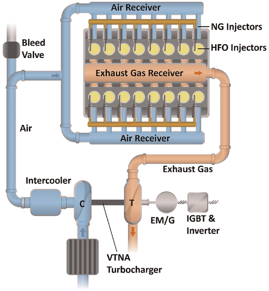
Advanced dual-fuel engine layout equipped with hybrid (electric) and variable turbine nozzle turbocharger (VTNA) with Insulated Gate Bipolar Transistor (IGBT) and Invertor labeled; adapted from Altosole et al. 93
The reliability and safety of marine propulsion have a significant role in ship operation. A fault tree analysis (FTA) method can quantitatively analyze turbocharger failures. An FTA estimates the system’s reliability, predicts the cause of failures in the turbocharger system, 95 and includes the scavenge air subsystems, such as air filter blockage, compressor fouling, turbine fouling (exhaust side), cooler tube blockage, and cooler air side blockage. FTA simulation results can improve the maintenance plan, propulsion system reliability, and turbocharger operation optimization. Other methods help mainline modeling to assess the common turbocharger fault effects on the propulsion system and performance. 96 Fouled turbo components significantly reduce the engine performance (22% power reduction), and heat exchanger fouling reduces power reduction by 1%. The complexity of modern marine internal combustion engines harmonizes with the new legislation’s requirements and is sensitive enough to optimize several subsystems. Advanced turbocharging systems are optimized for large (24.4 MW), two-stroke marine diesel engines and a two-stage turbocharging sequential ratio (30:70) using various rates of EGR and cylinder bypass. 97 A comparative assessment between the two engine configurations shows BSFC improvements in the region of 0.7–2.9 g/kWh.
The Miller cycle is gradually applied on low-speed marine engines to reduce NO x emissions because of its ease of implementation and low cost of operation. In this case, the coupling between the engine and turbocharger was considered. The reduced in-cylinder temperature prolongs the combustion duration and increases the exhaust gas temperature, moving the compressor operating points toward a high pressure ratio and mass flow rate. 98 The fundamental reason for this phenomenon is the uniflow scavenging by low-speed marine engines. The more the Miller cycle is applied, the more mass flows across the cylinder (which requires high boost pressure), and the turbocharger should be rematched. The relationship between boost pressure and the Miller cycle follows the original polytropic process in the cylinder. 98 The high-efficiency area of the compressor should include the operating point with the maximum Miller cycle, where the maximum Miller cycle and index of the original polytropic process decide the pressure ratio and the mass flow rate.
The reliability and service life requirements of marine turbochargers need to be increased. The key contributors to the life cycle cost of turbocharged IC engines are maintenance and operational costs. Turbocharger degradation occurs in the harsh marine operating environment, requiring frequent component replacement or retrofitting by replacing specific components (compressor or turbine) or the entire turbocharger. Ntonas et al. 99 have developed a marine turbocharger retrofitting platform that uses 1D models for calculating the turbomachinery components and integrates them and a diesel engine in a fully automatic process. In the modeled process, the entire diesel engine system efficiency shows a 0.27% improvement in specific fuel consumption. In service, turbocharger fouling and blade vibration are crucial reliability issues and critical problems that must be solved when designing the rotors. In real rotors, so-called mistuning arises, which is a slight deviation of the properties of the individual blades from the design parameters. For cases of integrated bladed discs of marine engine turbochargers, mistuning identification does not require costly scanning by laser Doppler vibrometers. 100 A simple laser vibrometer combined with a computational model of the integrated bladed disc can be used for mistuning identification. This method significantly reduces the cost of laboratory equipment and the time required to obtain the results. The development of new marine engine turbochargers can thus be significantly accelerated by automated processing. Turbocharger manufacturers can obtain complete statistical information on the parameters of blade disc mistuning caused by various influences in the production process.
Conclusions
This editorial paper attempts to clarify the current status of internal combustion engine technology in marine applications and how future technology can substantially contribute to decarbonizing road map. The key aspects extracted from this analysis are the following.
Internal combustion engines will continue to play a vital role as propulsion systems for marine shipping as the most efficient energy conversion systems. The global efforts to decarbonize shipping will determine an impetus for improving efficiency, reducing emissions, and introducing new low-carbon or carbon-neutral fuels.
Several promising zero-carbon fuels, net-zero carbon fuels, and LLCFs are available for displacing fossil fuels (i.e. hydrogen, NH3, methanol, DME, LNG, biofuels, NG, and others). Each has its characteristics, advantages and challenges and is presented in detail. The use of certain LLCFs such as NH3 and others in ship engines requires the development of new combustion systems, including dedicated fuel injection systems, to withstand fuel properties such as corrosion, low lubricity, and vapor pressure as well as unique safety issues.
Hydrogen presents significant challenges for marine engine applications. Low energy density, high liquefaction cost, and the lack of large-scale global distribution infrastructure represent significant obstacles to marine shipping applications. Green hydrogen densification can be achieved via NH3 and methanol, for example.
Ammonia is a promising non-fossil, zero-carbon fuel due to its liquid form (at low pressure). It solves transportation and storage problems onboard compared with those of hydrogen. It is a helpful hydrogen carrier with high energy density and has challenges with its autoignition, burn rate, and charge cooling.
Methanol shows a high potential for marine applications, thanks to the variety of production methods, ease of fuel storage, few modifications in existing engines, and low emissions. Different production pathways are possible, based on solid waste and low-value biomass, or on carbon capture technology and atmospheric CO2 direct capture.
DME is another promising synthetic fuel, which can be produced from methanol, and be directly used in diesel engines. DME has a high cetane number, is stored as a liquified fuel, and is characterized by a low sooting tendency. The production and distribution infrastructure is currently limited around the world.
Biofuels have the long-term potential to support shipping decarbonizing, thanks to the high biomass availability for transportation. Bio-derived diesel fuels can reduce the CO2 intensity of ships; they are more similar to current market fuels than other alternative fuels, with the potential for serving as drop-in replacements.
Liquified Natural Gas (LNG) can count on well-established infrastructure and production systems, with a small retrofitting cost. An efficient LNG dual-fuel engine can guarantee a reduction of GHG emissions by 25%. The LNG-converted propulsion system will represent a viable solution for marine shipping during the next one or two decades.
Dual-fuel combustion systems are necessary and well-suited as retrofit technologies on existing engine architectures, as well as for use in engines with long lifespans, to rapidly decarbonize the shipping industry. Both classes of typical engines (medium- and high-speed, four-stroke and low-speed, two-stroke engines) can improve performance by applying these new combustion technologies.
Dual-fuel systems can enable advanced combustion modes such as RCCI that are suitable for low-reactivity fuels such as NH3, methanol, and LNG. In general, HPDI or HPDF injection can be adopted with two separate injectors or a single coaxial injector.
Conventional and advanced turbocharging architectures are essential in ship engines to achieve high efficiency and clean combustion targets with carbon-neutral fuels. In particular, single-stage turbocharging has been adopted, eventually with variable geometry turbines, improving engine performance at part-load conditions. Additionally, hybrid turbocharging systems can be applied with an electrical generator embedded in the turbocharger body. A further option is represented by two-stage turbocharging for medium-speed, four-stroke engines combined with Miller cycle strategies.
Footnotes
Declaration of conflicting interests
The author(s) declared no potential conflicts of interest with respect to the research, authorship, and/or publication of this article.
Funding
The author(s) received no financial support for the research, authorship, and/or publication of this article.