
Abstract
In the quest for decarbonisation, alternative clean fuels for propulsion systems are sought. There is definite advantage in retaining the well-established principles of operation of combustion engines at the core of future developments with hydrogen as a fuel. Hydrogen is envisaged as a clean source of energy for propulsion of heavy and off-road vehicles, as well as in marine and construction sectors. A source of concern is the unexplored effect of hydrogen combustion on dilution and degradation of engine lubricants and their additives, and consequently upon tribology of engine contact conjunctions. These potential problems can adversely affect engine efficiency, durability, and operational integrity. Use of different fuels and their method of delivery, produces distinctive combustion characteristics that can affect the energy losses associated with in-cylinder components and their durability. Therefore, detailed predictive analysis should support the developments of such new generation of eco-friendly engines. Different fundamental physics underpin the various aspects of a pertinent detailed analysis. These include thermodynamics of combustion, in-cylinder tribological interactions of contacting surfaces, and blowby of generated gasses. This paper presents such an integrated multi-physics analysis of internal combustion engines with focus on hydrogen as the fuel. Such an in-depth and computationally efficient analysis has not hitherto been reported in the literature. The results show implications for lubricant degradation due to the use of hydrogen in the performance of in-cylinder components and the underlying physical principles.
Introduction
Hydrogen-fuelled internal combustion engines are increasingly considered as alternatives to the conventional engines with fossil fuel, particularly for larger road and off-highway vehicles. They are expected to play an important role in the future for various propulsion applications such as in marine, mining, agriculture, construction, haulage, and stationary auxiliary power plants to smooth out often-erratic power outputs from some renewable energy sources. In general, hydrogen is a promising, but challenging fuel for internal combustion engines. 1
The use of hydrogen as a fuel to generate mechanical motion dates back to 1807. 1 In 1820 Reverend W. Cecil published his work, based on vacuum created by burning a mixture of hydrogen and air. 2 This event occurred well before the mass-manufactured fossil fuel-based Internal Combustion Engines (ICEs). Hydrogen combustion produces higher flame propagation speeds, but with lower ignition energy. Therefore, it can be considered as a desired fuel for combustion. 3 However, the use of hydrogen as fuel entails some issues of concern, mainly associated with the lack of necessary infrastructure to produce and transport it with a minimal carbon footprint. Furthermore, its storage requirement in a safe, reliable, cost effective, practical and convenient manner is also of some concern.1,4,5 In addition, combustion of hydrogen in conventional IC systems poses some challenges, including the adverse effects that hydrogen can have on the metallic components such as embrittlement or excessive wear,6,7 among other issues. Hydrogen can also cause more rapid degradation of engine lubricant. 8 As the result, the lifespan of Hydrogen-fuelled Internal Combustion Engines (HICEs) is generally considered to be lower than their conventional hydrocarbon-fuelled counterparts. 9 The production of non-carbon emissions such as Nitrogen Oxides (NOx) must also be addressed, 10 as combustion of hydrogen produces higher adiabatic temperatures, resulting in elevated combustion temperatures with a higher NOx generation. 3 However, it is possible to reduce the NOx emissions to insignificant levels by adopting a leaner combustion strategy and a lower burn velocity. 1 In turn, this approach has adverse implications on the generated power. 11 In this regards, use of techniques such as water injection to dual-fuel Compression Ignition (CI) engines to reduce NOx and improve share of hydrogen energy was investigated by Chintala and Subramanian. 10 As Sens et al. 12 suggested, due to the existence of many unknown parameters, particularly in terms of a potential step-change innovative technological solutions in the future, it would be advisable to pursue hydrogen-fuelled powertrains in parallel to Battery Electric Vehicles (BEVs). This is in order to achieve urgent global Carbon Dioxide (CO2) reduction targets.
A comparative analysis of use of hydrogen, biofuel, and electrical power for sustainable transport was carried out by Shafiei et al., 13 who concluded that the use of hydrogen can be beneficial in reducing fuel import and consumer fuel costs, providing that the costs associated with development of the necessary infrastructure and vehicle ownership are also taken into account. As White et al. 14 highlighted more than a decade ago, continuous research into the advancement of HICE fundamentals, reduction of NOx (without compromising on generated power) and development of advanced engine components are considered as the main challenges, which are still present.
Zero- or one-dimensional (0D/1D) thermodynamic models have been developed to study various thermodynamic and heat transfer aspects of conventional fossil fuel-based ICEs.15–18 Such models have also been adapted to study HICEs, for example by Karagoz et al. 19 who investigated the performance of a hydrogen-fuelled Spark Ignition (SI) engines and the associated emissions. Their simulations showed that the use of hydrogen as a fuel improved the Brake Thermal Efficiency (BTE) at different engine speeds. However, the actual brake power decreased. They also noted that through an extremely lean combustion process with air-fuel ratios around twice the stochiometric air-fuel ratio (or Fuel to Air Equivalence Ratio, or FAER, of less than or near 0.620) for hydrogen, it was possible to achieve considerable reductions in the generated NOx emissions. Therefore, one of the main conundrums in the context of HICEs is the contradictory requirements between desired gain in maximum power and a reduction in NOx emissions. Under stoichiometric operating conditions and assuming constant volumetric efficiency and thermal losses, switching the fuel from gasoline to hydrogen can result in 17% reduction in output power according to Rana et al. 20 Thermal efficiency of HICEs can be 55.6% higher than for a gasoline engine (38.9% with hydrogen against 25% with gasoline), while the power output of HICE can reach 80% that of a gasoline-fuelled counterpart under laboratory conditions. 21
The performance of engines using hydrogen as an assistive fuel has also been investigated. For instance, Mathai et al. 8 investigated the differences in performance achieved through use of pure Compressed Natural Gas (CNG) and CNG combined with 18% hydrogen (HCNG) in Spark Ignition (SI) engines under relatively long duration testing (60 h). They noted that the iron deposits on the spark plugs, and cylinder liners was higher for the HCNG engines. In addition, kinematic viscosity, and Total Base Number (TBN) values for the lubricant (15W40) was significantly lowered with the use of HCNG (a drop of 1.3% in the kinematic viscosity and 15% in Total Acid Number or TAN). Subsequently, higher concentration of wear metallic partners such as iron and copper were also detected when using oil from HCNG. One of the main issues with the use of hydrogen as supplementary fuel to gasoline or diesel is the reduction in the volumetric efficiency due to the lower heating value of hydrogen, which results in lower torque and output power. 3 It also reduces BTE due to a reduction in combustion efficiency because of the addition of hydrogen. Adding hydrogen as a supplementary fuel to diesel-fuelled Compression Ignition (CI) engines increases the Brake-Specific Fuel Consumption (BSFC) but reduces the formation of soot. 3 Usman et al. 22 have also investigated the use of different fuels in an ICE including gasoline, CNG, and CNG and hydroxy gas (HHO) in 120 h engine tests. CNG-HHO blend resulted in significant effect upon lubricant viscosity, flash point and TBN mainly due to the addition of water as the result of combustion (5% after 40 h high loading conditions). This fuel also increased the various metallic wear particles. Furthermore, the reduction in Zn additives was higher for the CNG-HHO fuel (14.2%) in line with findings of Verhelst and Sierens 23 and Yildiz and Ceper 24 who used a zero-dimensional single zone SI engine thermodynamic model to study the effect of methane and methane-hydrogen blend. They found that the use of fitted double-Wiebe function provides better results for combustion modelling of these fuels.
Lubricants must also be compatible with the surge in water concentration in the crankcase, 1 with hydrogen combustion. This points to the potential use of either a demulsifying lubricant or a synthetic lubricant, which can form a solution with water. 25 The experimental investigation of Verhelst and Sierens 23 with a SI HICE showed that the properties of engine oil were significantly affected in terms of their quality. The concentration of various additives such as zincdialkyldithiophosphate (ZDDP), used as an anti-wear inhibitor was greatly decreased along with almost complete disappearance of esters, which can be explained as the ability of hydrogen in breaking down the double carbon – carbon bonds. Additionally, viscosity of the oil increased at cooler temperatures, whilst it was reduced rapidly at the higher operating temperatures. The viscosity index of the used oil was 99, which was considerably lower than that of the fresh lubricant at 163.
An interesting investigation on the effect of hydrogen on piston ring wear was conducted by Kindrachuk et al. 26 They proposed that hydrogen can be generated because of the breakdown or decomposition of lubricants in temperatures and pressures experienced inside the combustion chamber. This, in turn, can cause diffusion of hydrogen into the solid material structure mainly due to the energy provided through sliding friction. The tribological effect of the use of Modified Microalgae Oil (MMO) as a bio-lubricant for hydrogen powered ICE was investigated by Cheah et al., 27 in which they found that there could be around 10% reduction in the coefficient of friction through use of MMO. However, issues such as high acidity of the MMO should also be addressed.
An important aspect related to HICEs which remains insufficiently explored is the implication of hydrogen combustion on the tribological performance of in-cylinder components. There is indication that the current lubricant formulations should be altered in order to better serve HICEs in reducing their relatively rapid degradation.23,28 It is shown that the conditions of the in-cylinder components can significantly affect the generated contact pressures and temperatures during the combustion process.29,30 Therefore, an in-depth tribological investigations cannot be carried out in isolation from the combustion process itself. There are also some, albeit relatively minor, counteracting effects from in-cylinder tribology on thermodynamics of the combustion process based on the loss of useful work due to friction as well as loss of in-cylinder charge due to blowby. Blowby of hydrogen from cylinder can be quite high due to the rapid pressure rise as a result of a faster burn rate and the lower density of hydrogen. 23 Therefore, a hydrogen ventilation system is required to keep safe levels (< 1% vol) in the crank case. 1 These issues point to the need for developing coupled thermodynamic and tribological analysis/predictive models.
Considering the complexities involved in detailed thermodynamic analysis of the combustion process, achieved mainly through CFD, 31 and development of detailed multiscale in-cylinder tribological models,32,33 a fully numerical and detailed coupled model can be very time consuming from the computational perspective. This can also prevent wider use of such tools in industry as practical holistic analysis tools for engine designers. Therefore, developing combined multi-physics analytical models, which require lesser computational time, but provide sufficiently accurate results as presented in this study, seems to be the appropriate approach. Therefore, the aim of the current study is to develop an analytical model, combining thermodynamics of combustion with an in-cylinder tribology. To achieve this aim, a zero-dimensional thermodynamic model is developed and coupled with an analytical model for tribology of piston rings, including gas blowby. The approach expounded here utilises the existing models used for conventional engines and adapts those for the case of hydrogen-fuelled engines wherever the relevant data or relationships are available. This approach is original and has not hitherto been reported in the open literature, particularly in the context of conventional IC engines or indeed for the hydrogen-fuelled alternatives. Furthermore, the approach presented in the current study paves the way for more refined and complex model for analysis of IC engines in the future.
Analytical modelling approach
Thermodynamic model
The analytical approach for modelling the combustion process takes into account a zero-dimensional (0D) model, based on the first law of thermodynamics. For the system of concern, the first law of thermodynamics can be stated as:
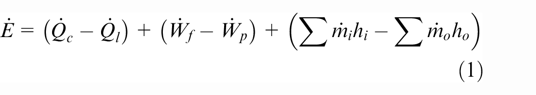
If the contributions from the gravitational potential and kinetic energies of gases is neglected, the total energy,

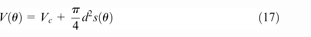
In addition, the rate of release of heat,

where,
The initial mass of the in-cylinder charge is determined, using the ideal gas law as:
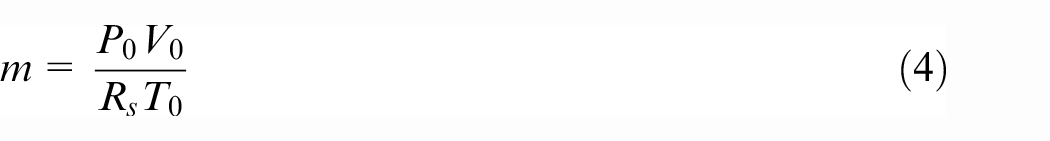
where,
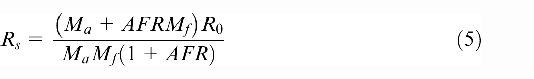
from which the in-cylinder fuel and air masses are determined as:
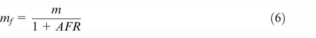
In Direct Fuel Injection (DFI) systems (air-aspirating operation) the total volume of the cylinder is fully occupied by air at the start of the process, thus:
The rate of heat loss through the combustion chamber,
where,
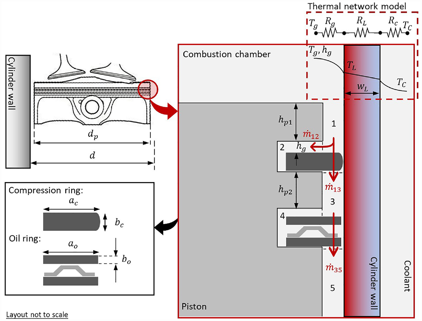
Schematic representation of the combustion chamber and the in-cylinder components including the piston, the top compression ring, and the oil control ring as well as the schematics of the thermal network model and gas blow by directions.
The radiation factor,
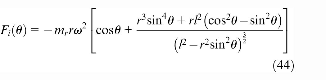
The rate of irreversible work originated from parasitic frictional losses is equivalent to the frictional power loss in the system, given as:

where, friction,
Finally, the rate of work done by the piston is:

where,
The enthalpy of the inlet flow to the system, which is due to injection of the fuel (considering its relatively small amount) can be neglected. Therefore, in the current study it is assumed that:
Considering the ideal gas law, in which the pressure, volume and temperature are considered as functions of the crank-angle, it follows that:

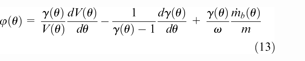
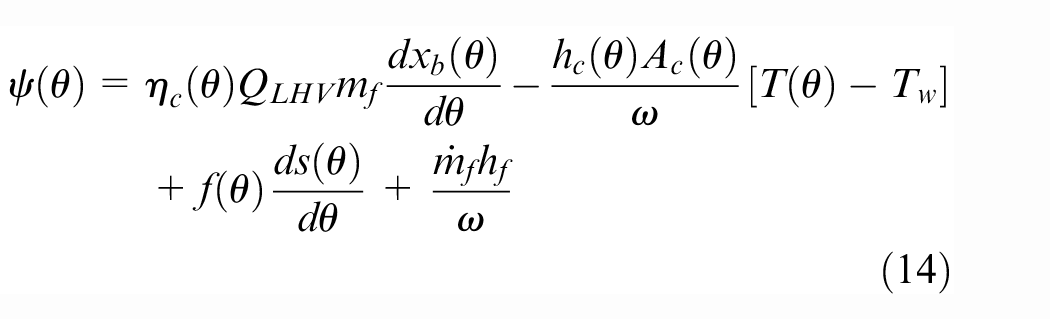
Substituting equations (2) to (6) into equation (1) along with expressing the rates of changes in terms of crank-angle, it follows that:
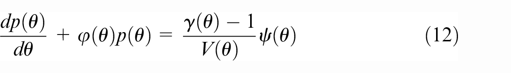
where:
Equation (12) is a first order non-homogeneous ordinary non-linear differential equation with variable coefficients. The initial conditions required for its solution can be stated as:
For gasoline fuel, the burn rate can be estimated based on the Wiebe distribution function. Thus, the burn rate for the fuel against the crank-angle becomes:
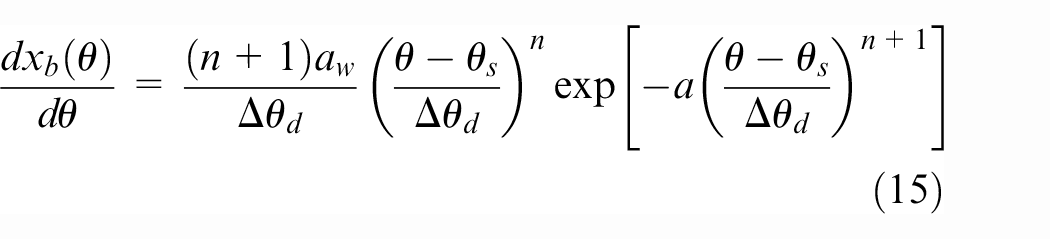
where,
The heat transfer coefficient within the combustion chamber can be obtained using the well-known relationship provided by Woschni, 45 amongst other suggested and widely used relationships.46–48 However, all these models have been developed for conventional ICEs. Demuynck et al. 49 investigated the compatibility of such models for HICEs and concluded that they cannot adequately describe the heat transfer accurately. Therefore, some modifications would be required. Some specific or modified heat transfer models for use with HICE’s have been proposed.50–52 However, these require some specific inputs, usually involving either experimental measurements or predicting the same through complex detailed numerical analysis. Therefore, to avoid variability in the results due to the uncertainty in such inputs from these proposed models, the relationship in equation (16), provided by Woschni 45 is used in the current study, similar to its use by Karagoz et al. 19 for HICE, and the same by Namar and Jahanian 53 for a Homogenous Charge Compression Ignition (HCCI) engine fuelled by hydrogen 35 :
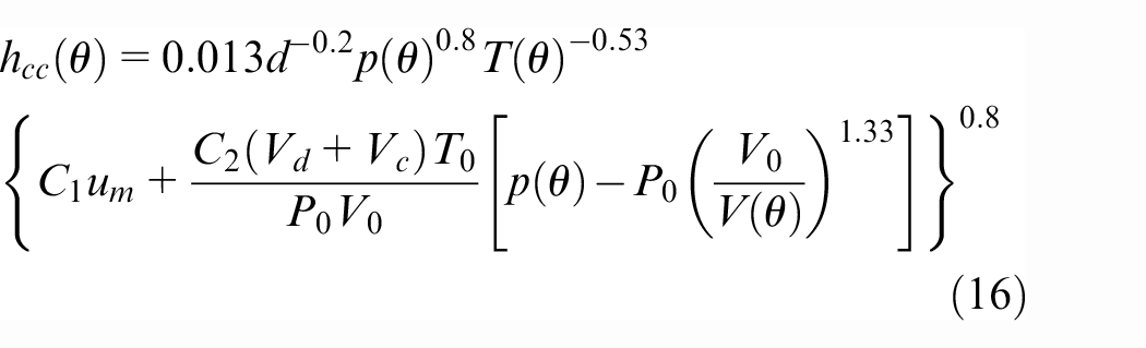
For the compression and power strokes
where, the instantaneous piston displacement, measured from the TDC is:
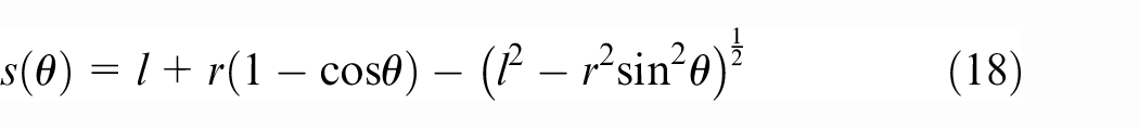
where,
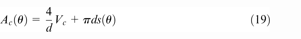
The heat transfer area in equation (8) can be estimated as:
Once pressure and temperature for each crank-angle is calculated through solution of equation (12) along with equation (11) (see subsection 2.4 for method of solution), it is possible to determine the engine performance parameters of interest.
Using a thermal network model presented in Figure 1, the average liner temperature is approximately given as:
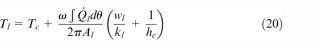
The liner temperature varies along the piston stroke in IC engines. 55 Therefore, a variable liner temperature can potentially provide a more accurate set of results, when the tribology of piston ring and cylinder contact is of interest. 29
Engine performance parameters of interest include the Indicated Mean Effective Pressure (IMEP), as well as Friction Mean Effective Pressure (FMEP):
Brake Mean Effective Pressure (
Tribological model
There are three main contributors to the in-cylinder friction in an engine. These include the Top Compression Ring (TCR), a three-piece Oil Control Ring (OCR) and the piston skirt. Developing a detailed numerical tribodynamics model for each component requires substantial detail as reported in Morris et al 55 ., Turnbull et al. 56 Combining these numerical models with the developed thermodynamic model would require significant computational power and time, which is beyond the aim of the current study. However, it is appropriate to develop reduced detailed, but realistic and representative tribological models using analytical approaches, particularly for the case of the piston rings which contribute the largest portion of in-cylinder frictional losses. In particular, the top compression ring, acting to seal the combustion chamber contributes the most to frictional losses and is considered as one of the main causes of failures of the in-cylinder components. Therefore, detailed analytical model for the piston rings is presented in the current study.
Piston rings experience a broad range of regimes of lubrication from hydrodynamics to mixed lubrication and onto direct boundary interactions. Therefore, in the current study, for predictive analysis a method developed by Gore et al. 57 for analytical evaluation of friction in mixed regime of lubrication for sliding contacts is combined with a hydrodynamic model developed by Rahmani and Rahnejat. 58
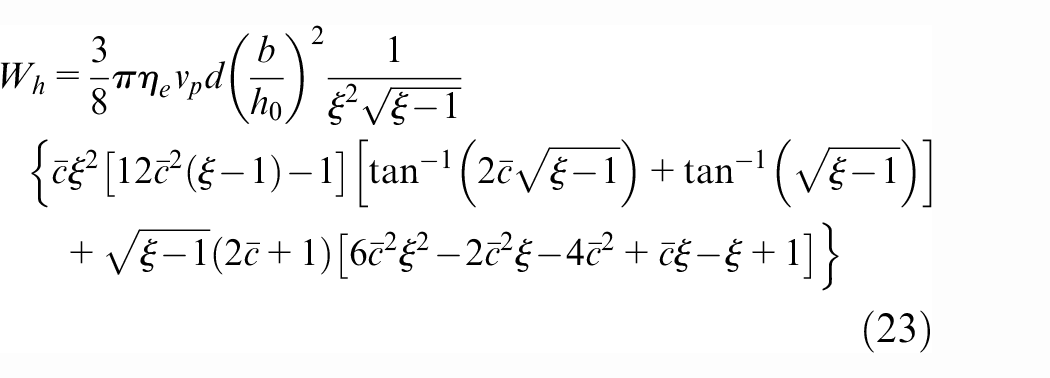
To determine contact friction, it is essential to determine the lubricant film thickness. The hydrodynamic load carrying capacity of a circular ring with a parabolic face-width profile is given as 58 :
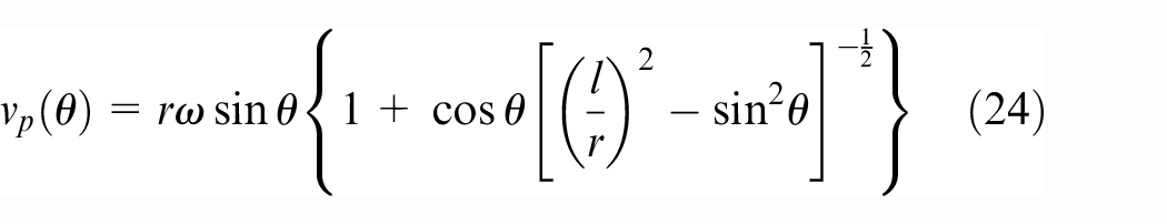
where, the piston sliding speed is given as 56 :
in which,
Also,

In addition, the effective viscosity of lubricant at the operating temperature can be evaluated using Vogel–Fulcher–Tammann relationship, widely known as the Vogel’s relationship 59 :
The empirical constants
The load share of surface asperities is determined as 57 :
where,
where, the indices 1 and 2 denote the ring and the liner respectively, and
The total load applied on the piston ring,
For instantaneous equilibrium of forces acting on the ring:

An iterative solution is used where the initially assumed minimum film thickness value is continuously updated by 61 :
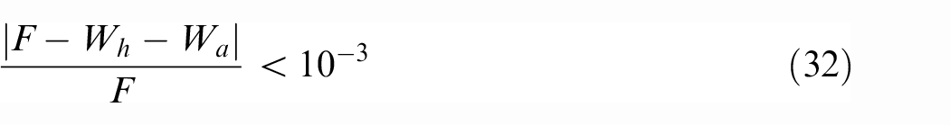
Successive iterations are carried out until the following convergence criterion is satisfied:
Once the minimum film thickness is determined, the viscous friction is obtained as:

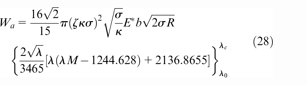
The contribution of asperity peaks’ interactions to generated friction in mixed and boundary regimes of lubrication is determined through 60 :

where,
where,
Thus, the total friction becomes:

Consequently, the power loss or the rate of loss of work by the top compression ring (TCR) is obtained as:

This is subsequently used in calculating work done by friction in the thermodynamic analysis.
A similar approach is applied to both segments of the three-piece oil control ring used in the studied engine. However, in this case, the effect of combustion gas on the applied force on the oil control ring is neglected, indicating that the pressure in the oil ring retaining groove is assumed to be equal to the crank-case pressure.
Combustion gas blow-by
The blowby flow of combustion gases is calculated, based on the methodology provided initially by Namazian and Heywood, 63 and applied by Baker et 64 and Turnbull et al. 56 to piston ring-packs similar to the engine subject of the current analysis. Figure 1 provides schematic representation of the blow-by flow components employed for the studied engine.
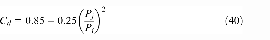
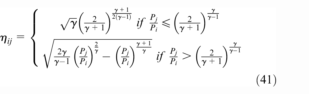
A major source of gas blowby is through the incomplete circular compression ring’s end-gap. The mass flow rate through the end-gap is calculated, based on the flow of gas through an orifice as:
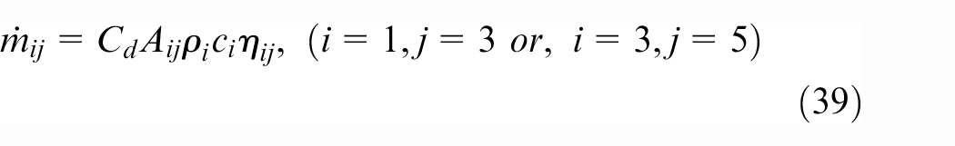
where,
and the compressibility factor is determined as 73:
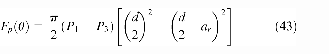
Depending on the balance of forces acting on the piston ring, it can translate axially inside its retaining piston groove. The resultant force on the ring is:

where,
where,
Thus, depending on the sign of the net force, the mass flow rate from volumetric region 1 to 2 or from 2 to 3 (Figure 1) can be determined by 63 :
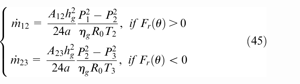
where, the viscosity of the blow-by gases is considered to be a function of the piston temperature, thus:
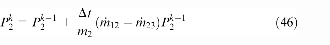
As already mentioned, pressure in the region 1 is considered to be the same as the in-cylinder pressure. The pressure in the region 5 is assumed to be the same as the crank-case pressure. However, to determine the pressure in regions 2 and 3, an iterative method of solution should be used (see subsection 2.4). Thus, the pressure in the regions 2 and 3 are updated as 63 :
and,
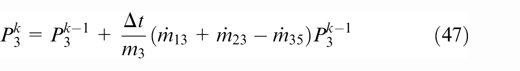
where,
Method of solution
For a naturally aspirated engine, pressure and temperature at the onset of the compression stroke,
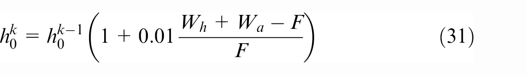
Therefore, the pressure at the next immediate crank-angle becomes:
Once the pressure is found for all the crank-angles, the temperature is updated using the ideal gas law (equation (11)). The new pressures are then calculated for the entire engine cycle until the difference between the pressures in two consecutive cycles,
The crank-angle steps required to achieve converged solution was found to be in the order of 10−4 rad. At each crank-angle step the subroutines associated with tribological computations and gas blowby are invoked in order to calculate the corresponding values and feed these back into equation (12).
For the tribological aspects, at each crank-angle step the piston ring operating conditions such as gas pressure behind the rings and the operating temperature are obtained from the combustion and gas blowby models in order to calculate the lubricant film thickness through quasi-static iterations, based on instantaneous equilibrium. The computational convergence for the rings-liner contacts is deemed as achieved when the condition stated in equation (32) is fulfilled. Subsequently, frictional work and power losses are evaluated. Further details on the solution method can be found in. 57 A flowchart of the simulation procedure is provided in Appendix A.
Model validation
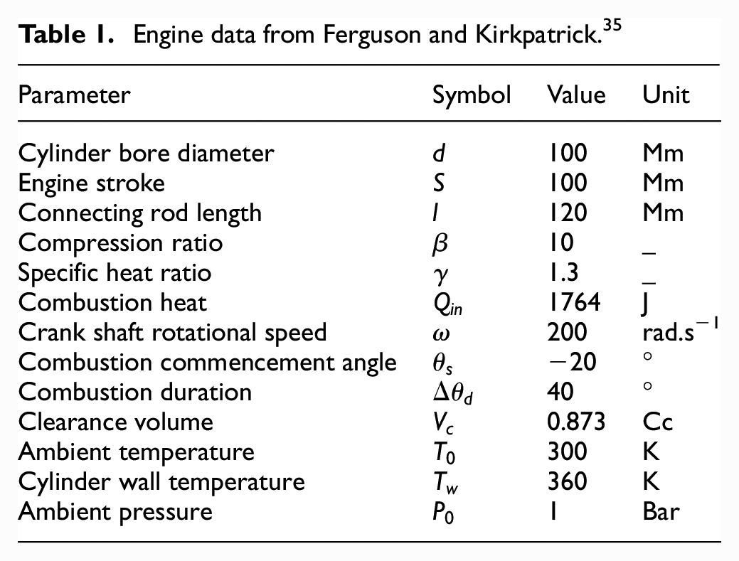
The developed thermodynamic model is validated using the data available in the literature, as well as the data measured from a single cylinder Honda CRF450R high performance motocross motorbike engine. Table 1 lists the input data which is used to validate the results from the developed model, together with those reported by Ferguson and Kirkpatrick. 35 For comparison purposes, the cylinder liner temperature was considered to remain unaltered. In addition, radiation heat transfer, as well as the lost work due to friction generated by in-cylinder components were excluded, a similar approach to that in the original reference. 35
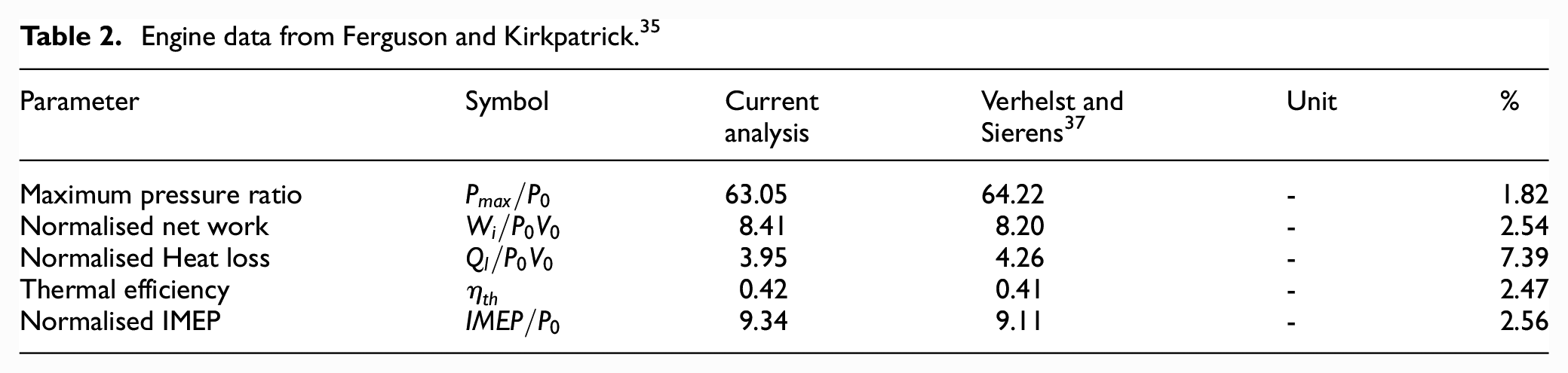
Engine data from Ferguson and Kirkpatrick. 35
The results for in-cylinder pressure against crank-angle are shown in Figure 2. In addition, the engine performance parameters are also compared with those reported in 35 in Table 2. As the comparison of the data in Figure 2 and Table 2 show, there is a very good agreement between the current predictions and those in. 35 There is only a slight difference in the reported heat losses. This may be due to the marginal differences in the implementation of heat transfer equation or the differences in the type of solvers used.
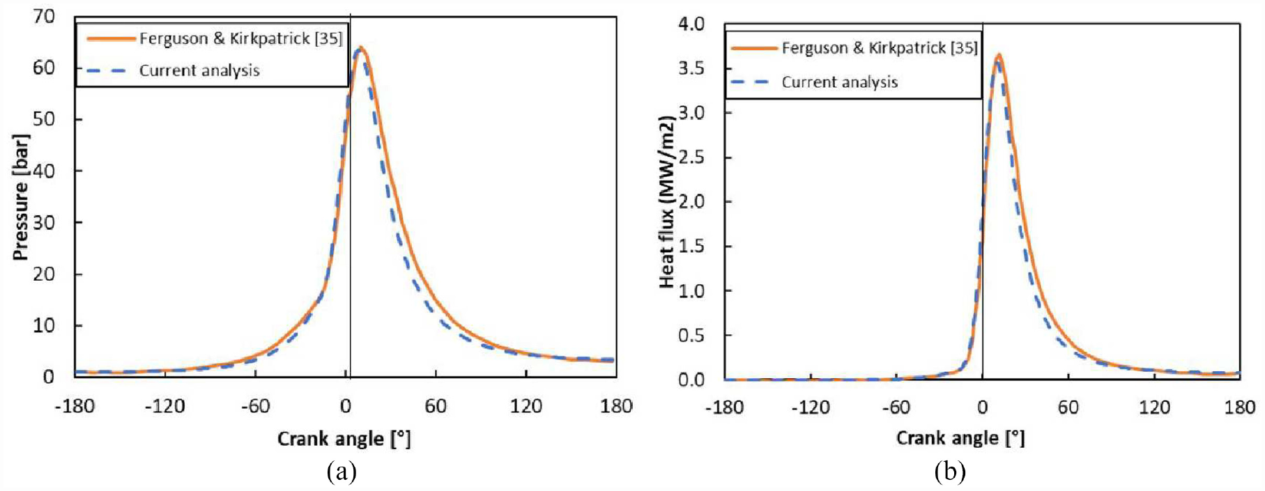
Comparison of: (a) in-cylinder pressure and (b) heat flux values.
Engine data from Ferguson and Kirkpatrick. 35
Post validation of the developed model against the available data from the open literature, 35 the predictions from the model are compared with the experimental measurements from a single cylinder naturally aspirated four stroke high performance single cylinder motocross SI Honda CRF 450R engine, mounted on a rigid support structure through a series of anti-vibration neoprene pads. This allows isolation of the engine from its supporting base. The engine gearbox output is aligned and coupled to an Oswald 250 kW transient dynamometer. The dynamometer and engine throttle were controlled by a Ricardo S3000/3345 system (Figure 3(a)). The engine test cell provides a controlled temperature and pressure environment. An OG 90 DN 1024 TTL encoder is utilised to monitor engine speed. A custom-made encoder was mounted to the engine’s balancer shaft (Figure 3(b)) to monitor crank and Top Dead Centre (TDC) positions. Cylinder pressure is measured using a spark plug-type Kistler 6081A40 piezoelectric pressure sensor inserted directly into the combustion chamber. All the signals are simultaneously acquired by a LabView software using a National Instrument (NI) BNC-2110 module and NI PCMCIA DAQ (Data Acquisition) card. More details of the engine set up can be found in. 65 Measurement instrumentation can impose systematic (fixed) and random errors in the measured data due to sensor calibration and unpredictable statistical errors. These errors and the overall uncertainty arising from them for the engine test set-up are reported in 66 and is provided here in Appendix B. The data was collected over a sufficiently long period of time after an initial running-in period with constant speed in order to ensure that thermal equilibrium in engine components is reached and the cyclic repeatability in the measurements is achieved. For the average in-cylinder pressure of 70 bars, the standard deviation of peak pressure is 3.65 bars over 20 engine cycles. The measured average liner temperature under the stated operating conditions is approximately equals 110°C, with the liner temperature variation of ±7 °C at the top and bottom of the cylinder liner.
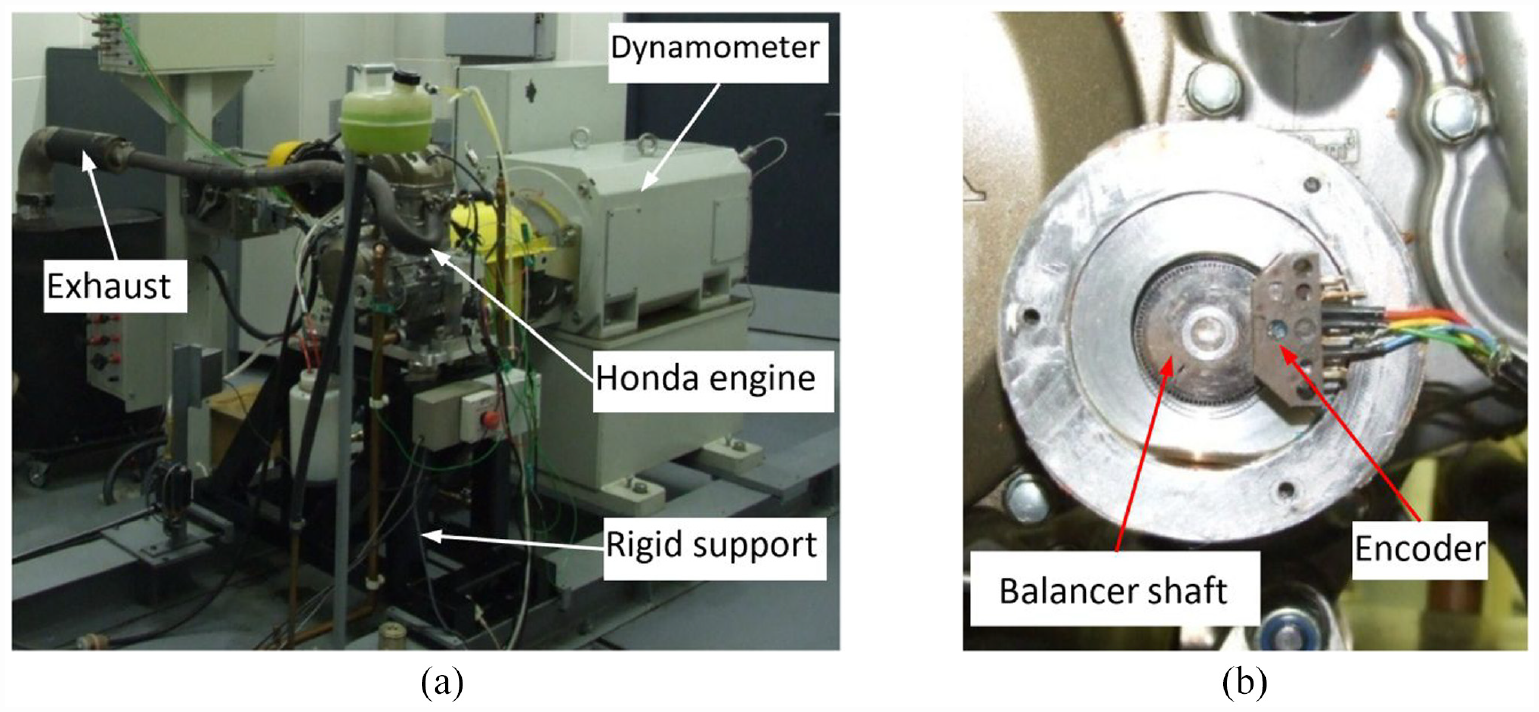
(a) Engine dynamometric test setup and (b) an encoder mounted onto the motorbike motocross engine balancer shaft. 65
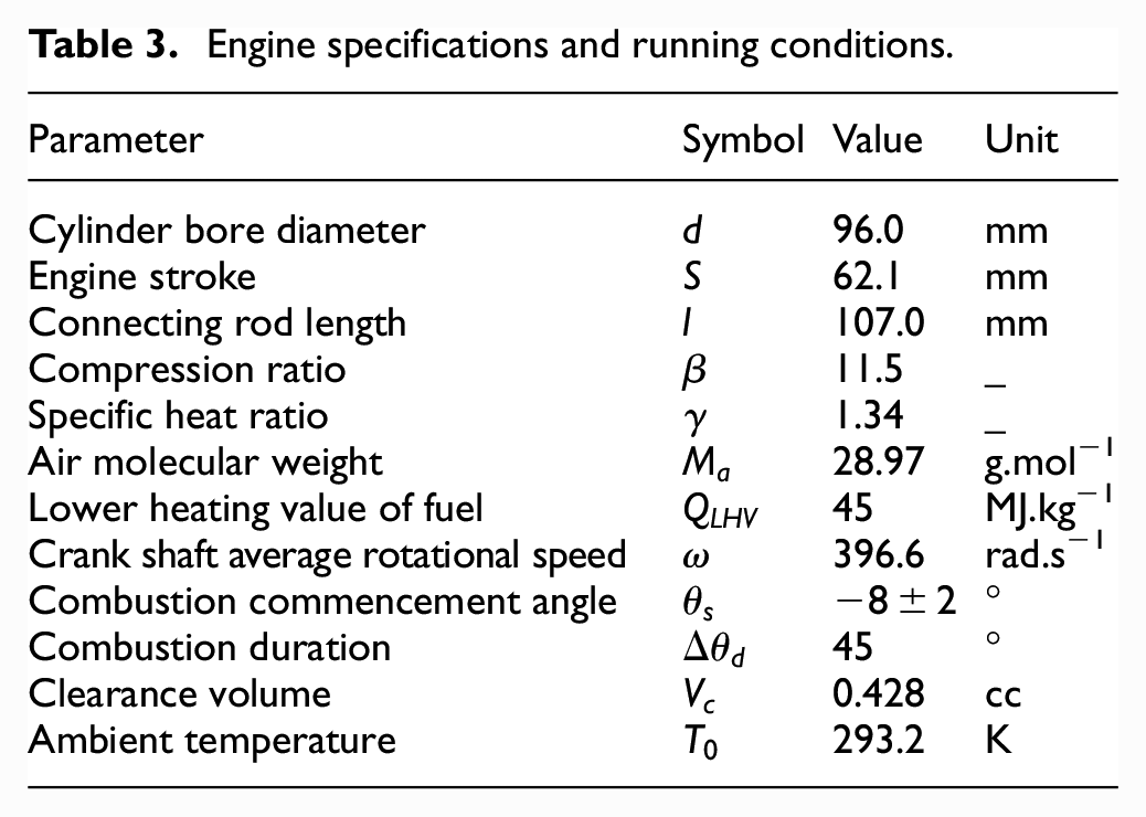
Table 3 lists the engine specifications used for the validation purposes. It should be noted that the exact duration of combustion is not known a priori. Therefore, lining the data for best fit between predictions and measurements is performed through observation.
Engine specifications and running conditions.
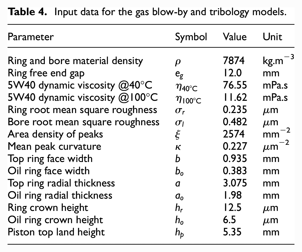
For predictive analysis, the complete integrated thermodynamic, gas dynamics (blowby) and tribology models are employed. The data in Table 4 lists the input data for the tribological and gas blowby models.
Input data for the gas blow-by and tribology models.
The comparison of the predicted in-cylinder pressure with the measured data is shown in Figure 4. Very good agreement is noted. Therefore, the comparison imparts further confidence in the use of the developed methodology for assessment of the changes in engine performance if hydrogen is used as a fuel.
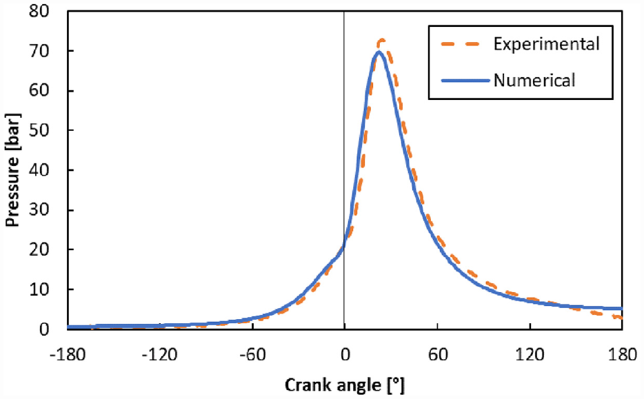
Comparison of measured and predicted in-cylinder pressures for the single cylinder Honda CRF450R motorbike motocross engine.
The tribological models of the piston ring-cylinder liner contact has been validated against measured data from the same engine, reported in Gore et al. 67 The gas blow-by model is also validated against the work of reported in Namazian and Heywood, 63 detailed in Baker et al. 64
Results and discussion
Effect of fuel and hydrogen delivery method
Figure 5 shows comparison of the results for in-cylinder pressure and temperature for alternatively fuelled hydrogen and gasoline studied engines at their stoichiometric air-fuel ratios. These are 15.03 for gasoline and 34.13 for hydrogen. 35 The lower heating value of the hydrogen fuel is 120 MJ/kg. 35 Figure 5 shows that at the stoichiometric air-fuel ratio, the generated pressure and temperature for hydrogen fuel is greater than that of gasoline. Under these stoichiometric conditions, the maximum generated pressure and temperature are 23.11% and 15.35% higher for the hydrogen fuel. As the result, the engine would produce 18.71% more torque and power. This estimate is based on the assumption that the engine would operate with a direct hydrogen fuel injection system. This finding is in line with the expected rise in power density for such a system noted in. 1
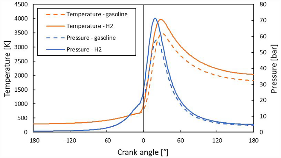
Comparison of the predicted in-cylinder pressure and gas temperature with different fuels.
With the Direct Injection (DI) configuration, the mass of cylinder content is estimated based on the compressed air only. However, if a carburettor or PFI fuel delivery system is used, where the air and hydrogen are mixed beforehand, then hydrogen would occupy a significant portion of the combustion chamber volume in comparison to the liquid gasoline. Therefore, the performance of stoichiometric air-fuel ratio when hydrogen is used as the fuel is expected to be 86% lower. 1 Figure 6 shows the comparison for in-cylinder pressure and gas temperature when two alternative hydrogen fuel delivery systems are used. The maximum pressure and temperature are 6.97% and 16.08% less than that of the gasoline-fuelled engine, yielding approximately 16% reduction in the engine power, which is in line with the expected drop as noted in. 1 These results imply that although higher power density can be achieved with direct injection due to higher combustion pressures, the generated higher temperatures would potentially produce higher NOx emissions, particularly that the air-fuel ratio used relates to stoichiometric combustion reaction.
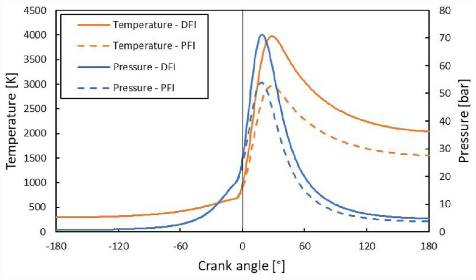
Comparison of predicted in-cylinder pressures and gas temperature based on different hydrogen fuel delivery systems.
Turning attention to the prediction of tribological performance of hydrogen-fuelled engines, Figure 7 shows the Stribeck oil film ratio,
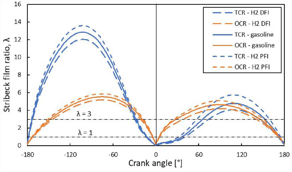
Variations of Stribeck lubricant film ratio for piston rings.
Figure 7 shows that during the latter part of the compression stroke and up to around 70° after the TDC for TCR, and up to around crank-angle of 25° past the TDC for the OCR, the regime of lubrication remains mixed. Therefore, the viscous action of the lubricant along with the interaction of opposing asperities on the counter faces determine the overall friction. In the case of the TCR, the regime of lubrication remains boundary up to around the crank-angle of 30° past the TDC. This implies that the contact behaviour in this region is mainly based on the ability of lubricant additives in forming tribo-films. However, in reality, there still would be some contributions from lubricant squeeze film action which can momentarily contribute to the load carrying capacity. This effect is not considered in the current study.
Figure 7 shows that the type of fuel used, and the choice of fuel delivery system directly influence the contact conditions. For instance, it can be seen that the use of DFI can result in harsher tribological conditions through extending the prevalence of mixed and boundary regimes of lubrication in the overall 4-stroke engine cycle.
An important factor which can affect the contact conditions and tribological performance of in-cylinder components is the temperature of the liner. Morris et al. 55 showed that the lubricant temperature in the piston ring-cylinder liner contact mainly follows that of the liner and only marginally exceeds it. Higher liner temperatures reduce the lubricant viscosity which in turn decreases the contribution due to viscous friction to the overall power loss. 29 However, this will increase the probability of enhanced asperity interactions, thus increasing the contribution due to boundary friction. The liner temperature is around 9.83% higher for DFI than PFI, found in the current study (see Figure 11), where it is assumed that the coolant temperature and coefficient of heat transfer remain the same. Therefore, with the DFI system not only the load applied on the ring increases, but also the liner temperature is higher because of an increased combustion temperature. Under these adverse conditions, it is expected that the share of boundary friction would increase. This is shown in Figure 8 for the TCR. As it can be seen, the contribution of boundary friction becomes significant after TDC in the case of a DFI system. At 20° crank-angle the difference is significant, being approximately 77.45%.
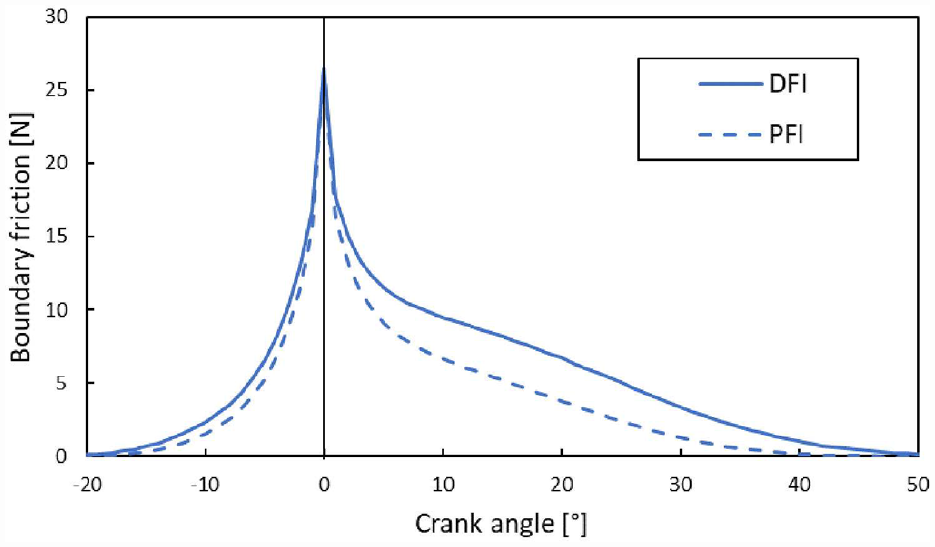
Top compression ring boundary friction contribution in transition from compression to power strokes for hydrogen-fuelled engine.
The implications of the changes shown in Figures 7 and 8 on the engine performance can be examined, by evaluating the engine performance parameters. Figure 9 shows BMEP and the generated power using hydrogen at different air-fuel ratios and with different fuel delivery systems. The cases for the gasoline fuel are also provided for benchmarking purpose. It is noteworthy that the generated power or BMEP is highest when the engine uses gasoline and runs rich at AFR = 12. The hydrogen fuel is examined at two different air fuel ratios corresponding to stoichiometric and lean burning conditions. The use of hydrogen on DFI system and at stoichiometric AFR provides power which is comparable with the gasoline engine running on rather a rich mixture. With leaner combustion the hydrogen-fuelled engine power tends to reduce. However, these high AFRs are often preferred as they allow mitigation of Nitrogen Oxide (NOx) emissions at the expense of a drop in power.
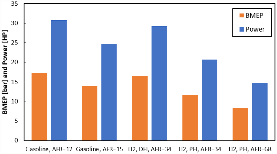
Engine performance parameters based on type of fuel, AFR and fuel delivery system arrangements.
In addition, the BTE and FMEP are shown in Figure 10(a) and (b). The BTE is slightly higher for hydrogen-fuelled engines, particularly if they operate leaner and delivered by a PFI system. The BTE for PFI hydrogen-fuelled engine at equivalence ratio of 2 is around 2.5% higher than that of a gasoline engine at the equivalence ratio of 0.8 as shown in Figure 10(a), whilst the corresponding FMEP is increased by 2.6% (Figure 10(b)). Here it must be noted that the BTE in this study is based on brake power which includes the power lost due to friction from the compression and oil rings for compression and power strokes only and does not include all the other friction losses. Caton 68 has shown that without including pumping losses and mechanical friction, the BTE values of up to 55% is possible in the thermodynamic simulations.
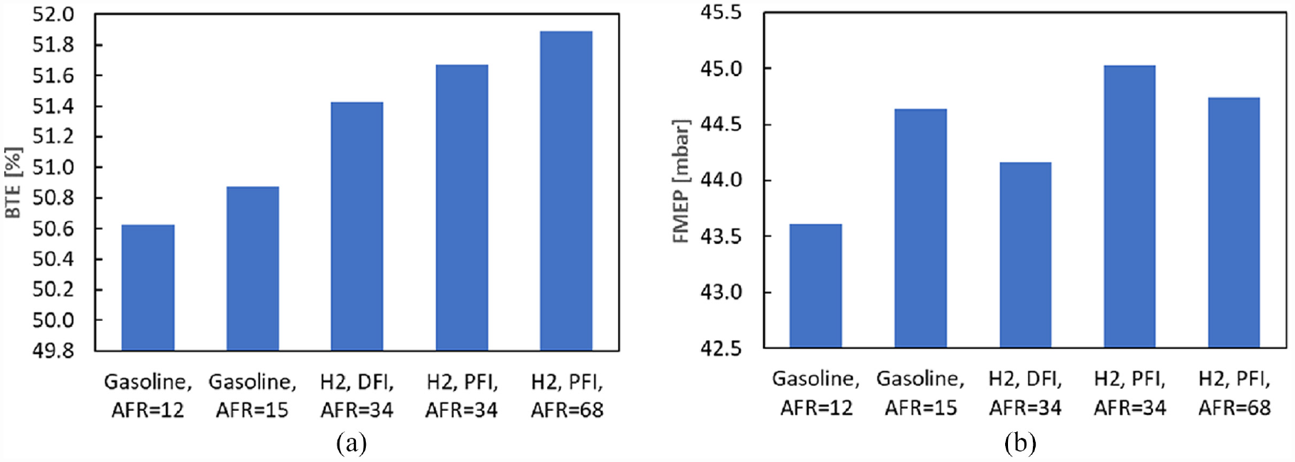
Comparison of: (a) brake thermal efficiency (BTE) and (b) FMEP for different types of fuel, AFR and fuel delivery system arrangements.
Temperature of cylinder liner is an important parameter as it determines the effective lubricant viscosity. 29 The predicted average liner temperature from the studied case is shown in Figure 11. It is clear that the average liner temperature is higher for DFI hydrogen-fuelled engine than that of the gasoline engine at their stoichiometric air-fuel ratios. The liner temperature drops for hydrogen fuelled engines when they are made to burn leaner to curb NOx emissions.
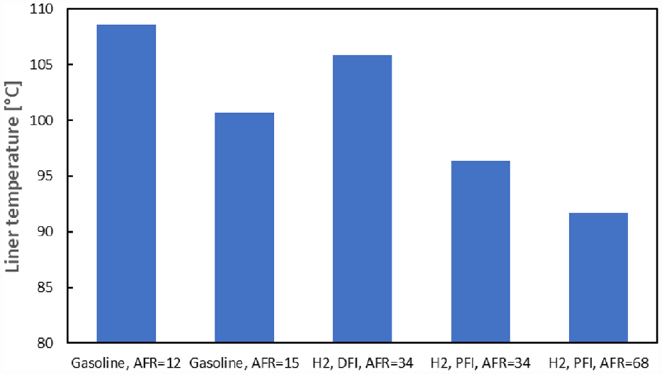
Predicted average liner temperature values.
Figure 12(a) shows the mass flow rate of gas through the piston ring-pack crevices for both gasoline and hydrogen-fuelled engines at their stoichiometric air-fuel ratios with DFI system. With the use of hydrogen, the blowby of gasses tends to by greater. However, it must be noted that in the developed gas dynamics model for hydrogen and with DFI system, properties of air are used throughout the cycle. Part of the gas flow to the back rim of the TCR tends to return to the combustion chamber during latter parts of the power stroke. Therefore, a negative mass flow (back flow) rate is indicated, similar to that reported by Namazian and Heywood for fossil-fuelled engines. 63 Comparison of the chosen fuel delivery systems for hydrogen fuel and its effect on blowby gasses is shown in Figure 12(b). It is shown that gas flow rate is higher in the case where a DFI system is used. Under PFI, the combined effect of hydrogen and air is considered when calculating the properties of in-cylinder gases. For a more precise gas dynamic model, the properties of the in-cylinder content after combustion should be included, also taking into account the generated water vapour and the NOx emissions. Based on these results and under both fuel delivery systems, and in particular with DFI, the crank-case ventilation should be considered in the engine design when use of hydrogen as fuel is intended. This is because some of the escaped gases remain with unburnt hydrogen. This action is necessary in order to make sure that volumetric percentage of such unburnt content does not increase to levels which can cause degradation of the engine lubricant in the sump as well as causing any unwanted ignition. 1
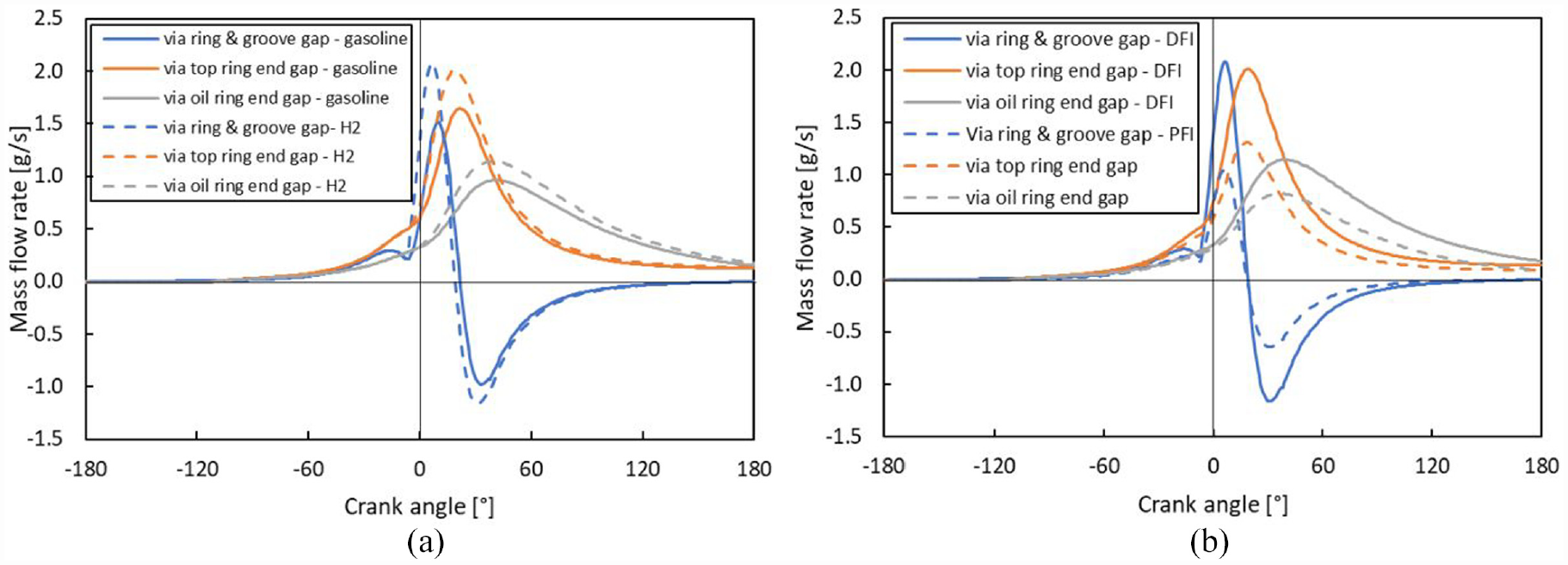
Mass flow rate through piston pack crevices: (a) for gasoline and Hydrogen (H2) fuels and (b) H2 fuel with DFI and PFI system.
Lubrication performance
There is a dearth of quantitative information regarding lubricant degradation for pure hydrogen- fuelled engines. However, there is evidence of the adverse effect of hydrogen on the engine oil, when it is mixed with other fuels such as CNG. As discussed earlier, Mathai et al. 8 showed that 18% hydrogen in CNG can cause oil degradation, including a drop of 15% in lubricant viscosity after 60 h of operation, whilst with CNG alone lubricant degradation was found to be rather negligible. Therefore, the performance of fresh 5W40 lubricant is compared with its degraded alternative with a 15% lower viscosity. The results for the top compression ring are shown in Figure 13. The used oil with reduced viscosity generates less viscous friction as would be expected. However, at the same time the contribution of boundary friction increases with the used oil owing to its reduced load carrying capacity. Nevertheless, overall, the reduction in the viscous friction is higher than the rise in boundary contribution. Based on the calculated FMEP for both TCR and OCR conjunctions, a reduction of 6.43% can be observed. One implication of lubricant degradation is the increase in friction in the parts of engine cycle, where the piston rings experience mixed regime of lubrication as shown in Figure 14(a) and (b).
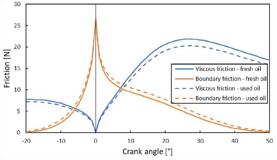
The effect of lubricant viscosity on generated friction in the TCR contact.
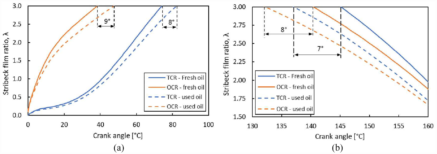
Transition to mixed regime of lubrication in TCR and OCR-liner contacts due to lubricant degradation: (a) 0 to 100 and (b) 130 to 160 degrees of crank angle.
Figure 14(a) and (b) show the variation in the Stribeck oil film ratio during the power stroke, where the transition from hydrodynamics to mixed regime of lubrication occurs for both TCR and OCR-liner contacts. With lubricant degradation, the contact between TCR and cylinder liner operates under mixed regime of lubrication for a further 15° crank-angle and in the case of OCR for a further additional 17°. In terms of percentage of engine cycle, these translate to 10.18%. As the result, it is expected that the probability of asperity contacts between the rings and the liner would increase. In the absence or lack of a sufficient volume of lubricant, expected with a degraded oil, severe surface damage to the components and scuffing of the liner surface may occur.
Discussion
It must be noted that the developed modelling approach should be considered as the first step in combined multi-physics analysis of in-cylinder combustion and lubrication study for future clean hydrogen-based engines. The developed model can be further improved by including additional details in thermodynamics, gas blow-by and tribological models. Hydrogen fuel-specific heat release and transfer models may need to be developed and improved further to obtain more accurate predictions. The gas blow-by model must be enhanced to distinguish between the initial cylinder content properties and those that may result post combustion. The tribological model for in-cylinder components can be further improved by including variation of temperature along the liner in piston tribodynamics.29,56,61 More detailed piston ring models which would take into account surface roughness effect, 57 as well as boundary friction properties of the formed tribofilms 62 should be included in future studies. Utilisation of hydrogen as a fuel can affect the mechanical properties of the solid surfaces in the eigne such as the liner and the rings. The proposed tribological model for prediction of mixed and boundary regime of lubrication and associated friction can be used with the inclusion of material properties of degraded surface components to provide more accurate prediction of contact performance for the engine at later stages of their life span. Use of AFM can provide more accurate values for modulus of elasticity and boundary coefficient of shear strength of the in-cylinder components’ surfaces32,62 which may be subject to degradation or creation of tribofilms.
In addition to changes in lubricant viscosity, covered in the current study, other lubricant physio-chemical attributes can also alter. Oxidation stability of the lubricant can be reduced due to depletion of antioxidants and accumulation of the oxidation products. Water as a hydrogen combustion by-product, not only affects the lubricant viscosity, but also potentially react with the lubricant additives. This can cause breakdown of tribofilms, leading to decreased performance and potential damage to engine. There should be more research for developing lubricants that are specifically formulated to resist the effect of hydrogen, water, and other potential contaminant by-products.
Conclusions
A novel combined analytical thermodynamic, gas blowby and lubrication model is presented to reflect the multiphysics nature of the in-cylinder combustion and tribological performance of hydrogen-fuelled engines. The model is validated against the data available in the open literature 35 and further refined, based on the measured data from an actual SI high performance motocross motorbike normally aspirated engine. Considering the assumptions made in this study, the conclusions of this fundamental study are surmised as:
Under relevant stoichiometric air-fuel ratios, hydrogen produces higher in-cylinder pressures and temperatures than the fossil fuel counterparts. Hence, higher output power under DFI system is achieved in comparison to a gasoline engine of same capacity. With PFI, the generated pressures and temperatures, and subsequently the engine power, remain somewhat lower.
The leaner the hydrogen combustion, the ever so slightly higher the thermal efficiency. However, the effect on reduction of power is more pronounced.
The BTE for the hydrogen-fuelled engine, irrespective of the fuel delivery method is higher than for the gasoline engine at their respective stoichiometric air-fuel ratios.
The generated volume of in-cylinder blowby gasses from the engine is more for DFI hydrogen-fuelled engine than for the gasoline and PFI hydrogen engine counterparts.
The liner temperature is lower for leaner combustion of hydrogen and use of PFI. The combustion, and subsequently liner temperature, directly affect the lubricant viscosity. This relationship, as well as combustion pressure acting upon piston ring conjunctions link engine thermodynamics with tribological performance.
The calculated FMEP, based on the lost mechanical work in piston rings’ contacts for DFI hydrogen engine is lower than that for the PFI system even at an air-fuel ratio twice its stoichiometric value. This highlights the importance of viscous friction in determination of FMEP.
The degraded (used) lubricant with a lower viscosity produces lower FMEP, but it also has a reduced load carrying capacity. Therefore, there are longer periods of direct boundary interactions, with increased boundary friction contribution. Under these circumstances the role of lubricant additives in the formation of low shear strength tribofilms become crucial. Therefore, any degradation or depletion of lubricant additives due to the use of hydrogen becomes an important issue for future investigations.
As discussed earlier, there is a considerable opportunity for developing experimental and numerical techniques, based on multi-physics multiscale approach expounded in this paper for investigation of modern engines particularly those that are to be powered by clean fuels such as hydrogen.
Footnotes
Appendix A: Flowchart of solution methodology
Appendix B: Sources of experimental errors and uncertainties
Errors and total uncertainty in measured parameters. 68
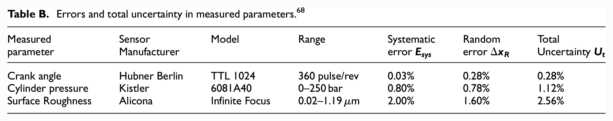
| Measured parameter | Sensor Manufacturer | Model | Range | Systematic error |
Random error |
Total Uncertainty |
|---|---|---|---|---|---|---|
| Crank angle | Hubner Berlin | TTL 1024 | 360 pulse/rev | 0.03% | 0.28% | 0.28% |
| Cylinder pressure | Kistler | 6081A40 | 0–250 bar | 0.80% | 0.78% | 1.12% |
| Surface Roughness | Alicona | Infinite Focus | 0.02–1.19 µm | 2.00% | 1.60% | 2.56% |
Appendix
Declaration of conflicting interests
The author(s) declared no potential conflicts of interest with respect to the research, authorship, and/or publication of this article.
Funding
The author(s) disclosed receipt of the following financial support for the research, authorship, and/or publication of this article: The authors gratefully acknowledge the financial support of the Engineering and Physical Sciences Research Council (EPSRC) under the Encyclopaedic program grant (EP/G012334/1), which enabled the development of some of the original gas blowby and in-cylinder tribological models, as well as measurement of experimental engine data used in this study.