
Abstract
Linear engines, or widely called free piston engines, have their advantages compared to conventional engines with crankshafts, for example, lower friction loss, compact structure, fuel adaptability, flexible compression ratio, etc. Among the linear engine conceptual designs and prototypes, Linear Engine Generator (LEG) incorporating a linear engine (internal or external combustion) and a linear alternator provides an alternative and attractive solution for hybrid electrical powertrains in transport applications. Due to the advantages of linear engines, hydrogen, synthetic hydrogen carrier fuels and biofuels are easier to adopt on LEG, making it an appealing technology for decarbonisation. This paper explicitly reviews LEG research and development on state-of-art solutions and recent progress in linear engine improvement, linear alternator design optimisation, and integrated LEG system control. Key performance indicators of the linear engine generator, like power output, thermal and electrical efficiency, etc., are summarised to present a general picture of up-to-date LEG development. Recommendations for further LEG development are provided at the end of the paper regarding the review outcomes.
Introduction
The concept of the free piston engine (FPE) was proposed about a century ago by Pescara Pateras for air compression applications, and a patent for spark ignition and compression ignition types was registered in 1927 1 and 1928, 2 respectively. The inadequate reliability and difficulty in achieving purely mechanical control mechanisms were among the main reasons the first-generation free-piston engines were abandoned around the 1960s. 3 Several concepts of the free-piston technology have been developed over time for different purposes; they include the FPE compressor, FPE gas generator, hydraulic FPE, and free-piston linear engine generator (FP-LEG). The FPE compressor was among the first successful applications of FPE technology and was the first version initially developed. 1 It used the energy obtained from the piston assembly to power a compressor. The FPE gas generator is one of the successful commercial FPE applications. It uses the exhaust gas from the engine to drive a gas turbine to generate power. SIGMA GS-34 was one of the reported engines that worked on the principles. 4 The hydraulic FPE combines an FPE with a hydraulic system: the energy of the piston assembly is converted to hydraulic fluid power. The technology is being proposed for hydraulic-powered systems. 5 The FP-LEG integrates the FPE with linear electric generator. The mover of the FP-LEG moves in a free linear motion between the dead centres. Gas forces acting upon the piston, the inertia and the load forces defined by the linear generator determine the mover dynamics. Therefore, there is no need for a crank control mechanism. 6 Because there is no linkage restricting the motion, negligible side forces act between the piston and cylinder liner, and frictional losses are low. 7 Some of the benefits of FP-LEG include its simple mechanical structure, with few moving parts; this makes it compact with a potential high power density, 8 and it is perceived to possess superior thermal efficiency to traditional piston engines of comparable size. 9 Moreover, the FP-LEG operate with a variable compression ratio (CR); this makes using different combustion technologies and alternative fuels possible.
Lately, researchers have renewed attention to the development of FPE, which also started to be called Linear Engines due to various heat addition methods. Several research groups have reported various configurations and test results. 10 The recent interest in FPE, especially FP-LEG, is attributed to the advances in system control and real-time actuation technologies, 11 the demand for improved fuel economy and the need to tackle the environmental impact of emissions from conventional fuels. The FP-LEG is well adapted to all forms (gaseous, liquid, and solid) of sustainable fuels like hydrogen and biofuels because of the variable CR and various heat input utilisation technologies available. The demand for sustainable energy utilisation, both industrial and domestic use and especially the electrification of the transportation sector, is the main drive for the current research and development efforts in FP-LEG.
Linear generators (LGs), as a critical power output unit for FP-LEG application, have attracted attention, and various institutions have researched the technology.12,13 The common configurations include the tubular-type and flat-type LGs. The designs with moving coil and moving magnet have been considered. 14 The typical permanent magnet (PM) arrangements in LGs investigated include the Quasi-Halbach, 15 Radial, 16 and Axial. 17 Investigations are ongoing for the development, performance optimisation and testing of LG to adapt to the unique characteristics of FP-LEG.18,19 One of the key challenges in FP-LEG application is its control because no rigid physical boundary restricts the piston dynamics. There have been a series of research efforts on FP-LEG to achieve a more successful operation through improved control strategy, especially for starting and continuous operation and generally improving its performance.
Many engine researchers and developers are interested in using FP-LEG as an advanced power source, offering increased performance and reduced emissions. 20 Target applications include:
On-board vehicle range-extender/generator: the FP-LEG is an opportunity to refuel a vehicle rapidly and thus extend the operating range by generating electricity on-demand (or charging a battery) on-board vehicles. The FP-LEG is expected to suffer smaller machine and thermal losses than current hybrid electric vehicle systems (HEVs). 21
Uninterrupted/emergency power systems: the variability in renewable sources for power generation currently presents a problem. The FP-LEG is an option to smooth the variability in renewable sources and peak-shaving applications.
Micro Combined Heat and Power (µCHP): the FP-LEG is complementary technology. It could be used as a conventional CHP system powered with renewable energy and yield no local exhaust gas emissions. 22
Auxiliary Power Unit: rather than power propulsion on-board vehicles, a smaller unit could power on-board systems at high efficiency on aircraft, ships, or other more extensive transport forms.
Researchers and developers have turned to systematic solutions to provide high-efficiency power generation systems regarding the ongoing electrification in the mobility sector. The effective control of FP-LEGs requires an integrated analysis of the system’s mechanical and electrical sides. Most of the review works on FP-LEG focused on either the engine development and control, 10 combustion, 23 or generator control. 24 A systematic evaluation addressing the research and developmental challenges and efforts of linear engines and linear generators is essential to clarify specific technical challenges and current progress and suggest the future research direction required. Therefore, this paper presents a systematic review of the progress and technical challenges facing FP-LEG development, focusing on improving the performance and control of the engine and generator. The paper’s second section discusses the state-of-the-art FP-LEG prototype testing and performance from several engine configurations and various types of energy input. As one of the critical components of the FP-LEG, analysis of the linear generator development and control optimisation are presented in the third section of the paper. The fourth section will examine the influential FP-LEG start-up, stable operation parameters, and various control strategies to achieve robust and continuous operation. Recommendations on FP-LEG future development are suggested.
Linear engine developments
The FP-LEG are classified according to mechanical configuration into different types: single-power piston (SPP), dual-power piston (DPP), single double-acting power piston (SDAPP), split-cycle double-acting power piston expander and compressor (DAPPEC), and opposed dual-power piston (ODPP), as indicated in Figure 1. Regarding the number of piston strokes per power cycle, two types exist; the two-stroke and the four-stroke type, and the two-stroke type is dominant. Based on the thermodynamic cycle types, while most FP-LEG operates on the conventional Otto/Diesel cycle, 25 the others operate on the Joule cycle to enable flexible energy resources.26,27 More published investigations have been on Otto/Diesel cycle FP-LEG than the Joule cycle FP-LEG because the former technology is more developed in the supposed FP-LEG operating power range than the latter. This made the transition from the conventional Otto/Diesel cycle technology to FP-LEG easier. Moreover, the features and operations of the FP-LEG depend on the type of technology adopted. The type includes and is not limited to the configuration of the major components, type of thermodynamic cycle, the number of strokes per cycle and the combustion mode. Because the FP-LEG can operate at variable CR and stroke, which makes using various fuels and combustion modes possible, this section focuses on the development and performance of the FP-LEG based on the combustion mode.
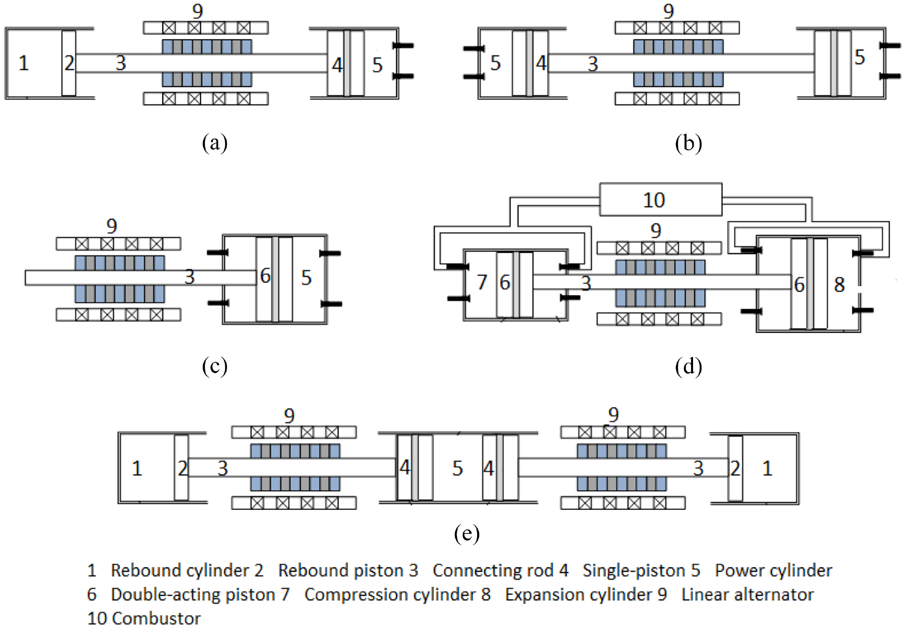
(a–e) Schematics of the SPP, DPP, SDAPP, DAPPEC and ODPP configurations of FP-LEG.
Prototypes of different heat addition methods
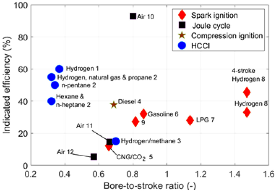
Although various studies have been published on FP-LEG, system performance data, such as power output and efficiency, were rarely reported. Among the published results, most were conducted through simulation modelling. Among the experimental results, few demonstrated the prototype’s continuous stable operation for a relatively long period (minutes to hours), suggesting that it might be still challenging to actualise stable running on a test rig. However, there are reports of successful commercial FP-LEG applications for backup generation; details of the commercial FP-LEG deployment are discussed later in the paper. Different combustion modes are possible with FP-LEG depending on the thermodynamic cycle. For the Otto/Diesel cycle FP-LEG, compression ignition (CI) combustion and spark ignition (SI) combustion are standard, and some cases of Homogeneous Charge Compression Ignition (HCCI) combustion have been reported. In the Joule cycle, FP-LEG, constant pressure energy addition is common. This section focuses on the performance results of the FP-LEG test rig. Table 1 and Figure 2 summarise the test results from works in the open literature, including design features. It is worthy of note that in the cases of compressed air Joule cycle FP-LEG, where the energy input comes from compressed air, the calculation for efficiency is different compared to the others where the energy input comes from fuel and is released through combustion. In the cases of the Joule cycle FP-LEG, the efficiency calculation is based on the ratio of work done or electrical energy produced to the energy content of the compressed air, without considering the calorific value of the fuel utilised to produce the compressed air. In contrast to the other cases, the efficiency is calculated based on the energy content of the fuel used directly and work done, or electrical energy produced. That explains the varied efficiency range for the Joule cycle FP-LEG prototypes.
FP-LEG test rigs design features and system performance data.
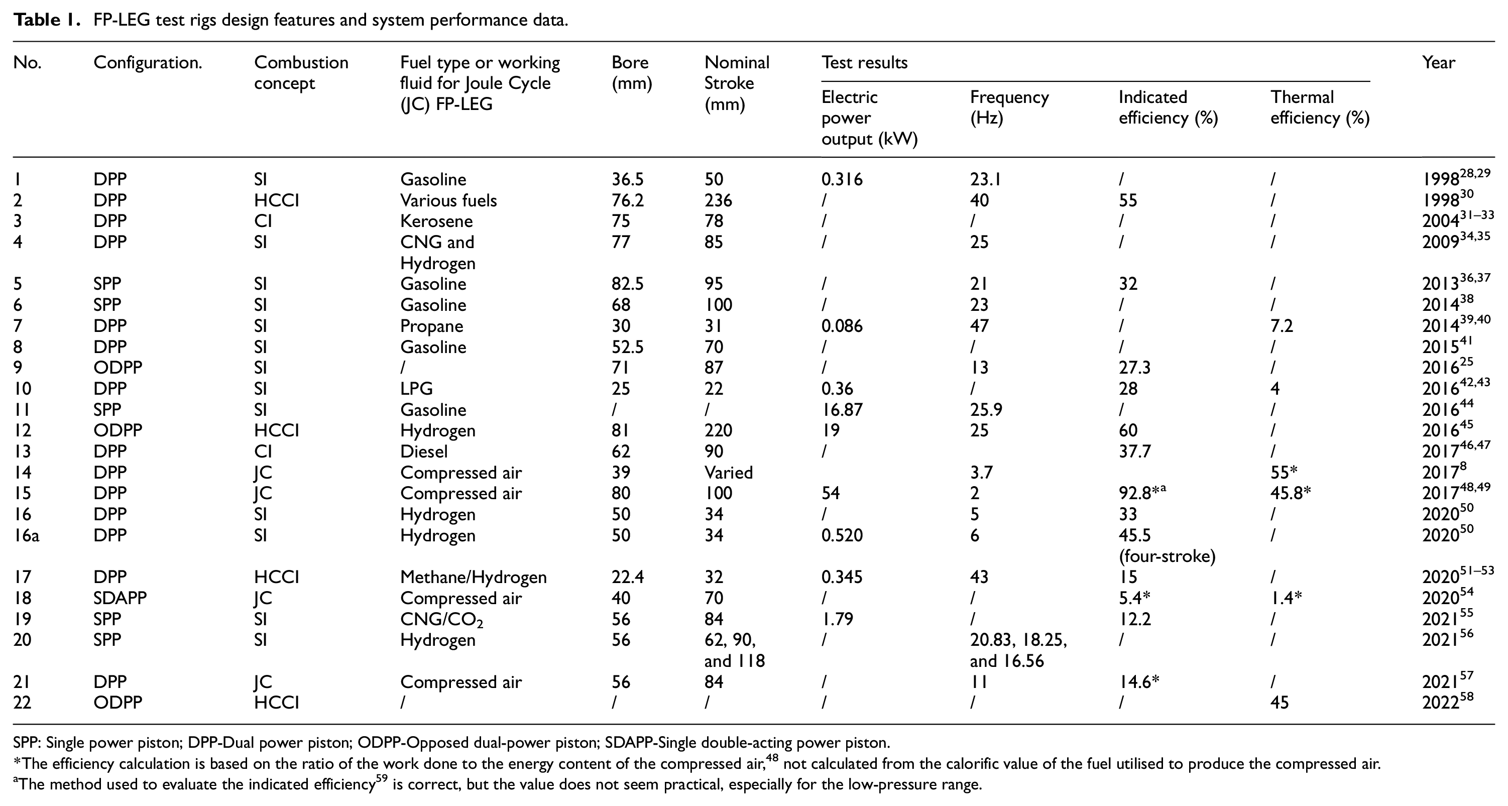
SPP: Single power piston; DPP-Dual power piston; ODPP-Opposed dual-power piston; SDAPP-Single double-acting power piston.
The efficiency calculation is based on the ratio of the work done to the energy content of the compressed air, 48 not calculated from the calorific value of the fuel utilised to produce the compressed air.
The method used to evaluate the indicated efficiency 59 is correct, but the value does not seem practical, especially for the low-pressure range.
Spark ignition combustion
SI combustion is an established technology. It is widely considered for FP-LEG application because the spark initiation event could control the piston assembly motion through combustion phasing. 50
West Virginia University was among the first to develop the FP-LEG test rig in the mid-1990s.28,29 The rig is of DPP configuration with port injection and loop scavenging; engine details are in Table 1. Rich gasoline mixture ensured combustion and engine operation was stable under different working conditions. Results showed that ignition-timing control was critical to successful operations. At no-load and low load conditions and advanced ignition resulted in adverse work. However, the adverse work and cycle-to-cycle pressure variation were eliminated at high load conditions and retarded ignition timing. Retarding ignition increased the engine’s stroke and peak pressure, and the results further suggest that SI operation is undesirable, and CI is desirable in HCCI mode.
The German Aerospace Centre (DLR) developed an FP-LEG in 2013 aimed at a hybrid drivetrain. 36 The SPP two-stroke head-loop scavenging engine details and its performance are found in Table 1 and Figure 1(a). The rebound system at the opposite end of the combustion chamber stores energy from combustion to regulate the piston motion. The quasi-autarkic mode results suggested that at 50 Hz, a power output of 25 kW could be achieved. 37 A comparison with a conventional car shows that with a 50 kW FP-LEG the fuel consumption can be reduced by 28%. 60 Subsequently, in 2016 DLR developed an ODPP two-stroke SI FP-LEG prototype. 25 The rig incorporated a supercharger with boost pressure. The boost pressure created the necessary pressure difference between the intake and exhaust ports. A targeted speed of 15 Hz could not be achieved due to control restrictions. The low engine efficiency is attributed to low combustion efficiency. Analysis of the combustion at 20 Hz using the cylinder pressure analysis of the fuel burn rate indicates that the burned fuel fraction did not exceed 82%. This implies that exhaust gas recirculation (EGR) would be beneficial in improving the engine’s performance.
Toyota Central Research and Development Labs Inc. developed a two-stroke SPP FP-LEG rig in 2014. 38 The design used a stepped-shaped piston called a W-shaped piston. The W-shaped piston has a smaller combustion end and a larger diameter gas-spring end. A permanent magnet generator located at the larger diameter end ensures the combustion cylinder’s heat does not affect the generator magnet. Although several abnormal combustions occurred during testing, a stable and continuous operation was achieved.
Ulsan University achieved continuous and stable operation on a two-stroke FP-LEG using propane as a fuel around 2014.39,40 The test focused on vital engine parameters, including fuel quantity, equivalence ratio (ER) and ignition timing. The influence of ignition timing on the performance suggests that an ignition delay of 1.5 ms leads to maximum power output, piston stroke, frequency and in-cylinder pressure. Ignition delayed beyond 2.0 ms led to general decreased performance. Performance increased with the ER from 0.8 to 1.0 and decreased beyond 1.0 ER. A power output of 95 W was recorded, 39 while non-optimised parameter testing achieved 86 W.
An investigation on a DPP two-stroke uniflow scavenging FP-LEG was presented in 2015 by Jia et al. 41 Successful ignitions were achieved through mechanical resonance using the linear electric machine. Misfiring occurred every few cycles, and cycle-to-cycle variation was significant. The unstable operation is attributed to non-optimised ignition timing, variation of the mixture formation during star-up, and the undersized electric machine’s brake. The electric machine brake would trigger and retard engine speed when it reached the motor speed threshold; this affected gas exchange processes resulting in misfiring on subsequent cycles. Moscow Polytechnic University developed a two-stroke FP-LEG rig. The rig contains two modules, each consisting of an SPP FP-LEG. The maximum electric power was 16.87 kW at 25.9 Hz. 44
Korea Advanced Institute of Science and Technology investigated a two-stroke mini FP-LEG.42,43 The pistons and the cylinder liner were made of ceramic to minimise heat and friction losses, and the engine used a crossflow scavenging and liquefied petroleum gas (LPG) fuel. The power output increased with the resistance at a low range until a peak power was attained and decreased with further increased resistance. Cyclic variation was predominant at lower loads and improved at higher loads. The engine achieved 28% indicated efficiency, and the low efficiency was attributed to a substantial portion of fuel short-circuit losses through the exhaust ports because the test was conducted at high airflow rate conditions. They recommended optimising the gas exchange process to improve scavenging and minimise misfire.
Newcastle University investigated the performance of a loop-scavenged hydrogen-fuelled DPP FP-LEG in two-stroke and four-stroke modes. 50 The four-stroke cycle was achieved with active valve operation, and the alternator was the controller used to guide the piston according to a pre-set displacement profile. Test data revealed that the ER affected the engine performance. The in-cylinder peak pressure increased with the ER, while the peak pressure timing decreased. The peak pressure timing and in-cylinder peak pressure decreased with the engine speed. The two-stroke and the four-stroke cycle achieved an indicated efficiency of 32.3% and 45.5%, respectively. The authors recommended that an appropriate ER range is required for every specified FP-LEG parameter to curb undesired operations.
Compression ignition combustion
West Virginia University developed a second-generation two-stroke loop scavenged CI FP-LEG test rig in the late 1990s 32 and early 2000s. 31 The starting solenoids of the engine could not provide CR exceeding 4:1; therefore, the engine operated with spark-starting aid. The engine could not run on diesel because it fouled the spark plugs before the engine could start; instead, kerosene was used. 33 Because of some design problem, the engine operated for a few seconds/minutes before equipment failure.
Sandia National Laboratories (SNL) developed a two-stroke DPP FP-LEG in 1998. 30 The engine employed HCCI combustion for improved thermal efficiency and reduced emissions. Eight different fuels were tested at fixed ERs. Test results showed that indicated efficiency between 55% for hydrogen and 40% for n-Heptane were achieved. 30 The results suggested that the high combustion rate at high CR approaches the constant volume combustion condition, which is the primary cause of high efficiency. It is notably true for fuels with a single-stage combustion process. In 2016 SNL developed an ODPP FP-LEG. 45 The opposed-piston configuration was meant to achieve engine self-balancing during combustion, and a successful low ER HCCI hydrogen combustion was achieved. The indicated efficiencies commonly reached 55%, with the potential for higher efficiency. The testing operation proved insufficiently robust because of challenges in controlling engine parameters to obtain appropriate mixture composition and CR.
Chongqing Jiaotong University investigated a loop-scavenged DPP FP-LEG. External compressor provided the pressurised air for the gas exchange process to improve scavenging.46,47 Investigating the influences of injection position and alternator starting force on the ignition revealed that the higher starting force did not certainly produce better ignition. However, it increased the possibility of the engine starting fast and gaining a higher CR. Data suggest proper injection timing enhanced the combustion, promoted higher CR, and reduced misfiring, while unsuitable starting force led to incomplete combustion.
Joule Cycle free-piston linear engine generator (JCFP-LEG)
Lately, two kinds of JCFP-LEG technologies have generated research interest; the most common type is based on low-grade energy addition from external heat sources, while the other works on the complete Joule Cycle principle. In this section, both test and simulation studies are presented.
Newcastle University investigated air-driven DPP FP-LEG. 8 Compressed air, supplied by an external compressor, was used as the energy source that drove the expansion process alternatively in each cylinder. The cycle-to-cycle variations in piston velocity were high, indicating difficulty in achieving robust valve timing operation. The peak voltage, velocity, and conversion efficiency increased with the driven pressure. Frequency increased with the driven pressure but seemed more sensitive to the pressure at the low-pressure region because the friction loss is proportional to the in-cylinder pressure. Universiti Teknologi PETRONAS investigated a similar rig. 57 Increased inlet pressure increased engine stability and power output and showed negligible frequency effects. Extended inlet valve opening duration led to increased power but decreased indicated efficiency. Incomplete expansion and subsequently energy waste through the exhaust were responsible for decreased indicated efficiency at extended inlet duration.
The University of Notre Dame examined a closed-cycle FP-LEG in Micro-electromechanical systems (MEMS). 61 The piston movement was achieved by expanding working fluid through external thermal energy input on the contact surface. The power output increased with heat input despite decreased frequency caused by extended piston strokes. Thermal efficiency of 0.2% was achieved at 1.08 bar and a 5 K temperature gradient. The low efficiency is associated with minute input heat-rate from low temperature, pressure gradients and parasitic losses. Because of low efficiencies in the MEMS scale, an open-cycle macro-scale FP-LEG was developed.62,63 The intake duration and pressure influenced the performance indicators, similar to the result by Jia et al. 26 An indicated efficiency of 18% at 2.5 bar, 373 K, was achieved. 62 Increased intake temperature did not significantly affect engine performance for a fixed intake duration, and an optimal intake duration existed, which maximised energy conversion, similar to the results in Ngwaka et al. 64
Beijing University of Technology developed air-driven DPP 48 and SDAPP 54 FP-LEG test rig. The DPP and SDAPP rig’s performance characteristics were similar. However, the SDAPP efficiency is significantly lower, contrary to expected, because friction losses should be higher in the dual-piston configuration, thereby adversely affecting its energy footprint. Intake pressure and valve timing significantly influenced power output. 49 The engine’s motion stability improved with increased intake pressure 65 because higher pressure will overcome most engine disturbances, especially from the load. Expander recompression decreased the efficiency and improved power output; this would occur because recompression will increase frequency, directly affecting power output. Optimum performance at various valve timing differed and depended strongly on the frequency. Increased frequency resulted in decreased piston amplitude; this occurred because whilst the frequency increased, the intake duration would decrease, which would result in reduced air intake per cycle.
Stouffs and Mehdizadeh66,67 presented one of the pioneering contemporary simulation analyses of the JCFP-LEG in the late 1990s. The closed-cycle JCFP-LEG used helium as the working fluid. The engine configuration is unconventional from recent designs because it uses two SPP FP-LEG and a rotary motor that drives the displacer.
In 2012, Newcastle University incorporated FPE technology in reciprocating Joule Cycle engine design for CHP applications. 22 The availability of components that could withstand high temperatures, lubrication and sealing problems prevented its practical designs. In 2014, the design was revised for only electric power, 68 and a prototype test rig of an air-standard Joule cycle FPEG with dry lubrication was developed. 69 The FP-LEG dry friction model was analysed, 70 and the coupled engine dynamic and thermodynamic model was developed. 71 Results indicated that the engine performance depended on the working fluid, pressure, valve timing and electric load. The valve timing and electric load should be optimised depending on engine efficiency and power output preference.
Newcastle University and Durham University had developed the second-generation DAPPEC rig; the configuration is shown in Figure 3. 64 The semi-closed JCFP-LEG adopted argon-oxy-hydrogen combustion technology, and argon was the primary working fluid. Argon as the working fluid boosts engine efficiency because of its higher specific heat ratio, which does not decrease at high temperatures, unlike air. 72 It also has the advantage of eliminating the oxides of nitrogen caused by the absence of nitrogen and leading to increased combustion flame temperatures. Substituting air with argon resulted in over 50%-improved efficiency. 71 The ability of the engine to recover from disturbance was considerably lower at short intake duration and more robust at increased intake duration. Efficiency could be further improved by extending the expander exhaust duration. Similarly, the University of Birmingham is developing an open-cycle JCFP-LEG for marine operations,73,74 and the engine will be powered by ammonia and hydrogen blend. 27
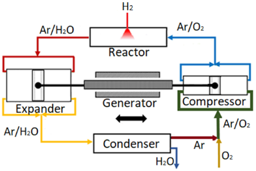
Schematic configuration of the proposed semi-closed cycle FPEG. 64
The latest commercial FP-LEG applications
There are successful applications of FP-LEG technology beyond the laboratory to commercialisation. Mainspring Energy has deployed several of its 230 kW FP-LEG auxiliary power unit in an operational environment for backup generation. Lineage Logistics will deploy about 150 Mainspring’s FP-LEG to its facilities and explore using green fuels. 75 The high compression ratio natural gas-powered ODPP LEG employs low-temperature combustion to achieve chemical to mechanical energy conversion, and the piston assembly motion is electrically controlled. The engine could achieve 45% thermal efficiency and can ramp up or down at 20 kW/s. 58 The Aquarius Engines hydrogen-powered FP-LEG for onboard power generation in hybrid vehicle applications is under an operational demonstration. 76 However, the version for the stand-alone electricity generator reported a five million EUR purchase order to supply the power solutions after the successful completion of a series of tests in an operational environment. The 10 kg engine incorporates a central double-acting combustion cylinder with a single-piston configuration, and the engine is air-cooled because it requires no lubrication and uses graphite piston rings. 77 Libertine is developing commercial opposed-piston FP-LEG technologies in partnership with MAHLE Powertrain, focusing on engine control and renewable fuels. Tests with the two-stroke FP-LEG using wet bioethanol have been successful and have moved on to blends of compressed natural gas and hydrogen, targeting 100% hydrogen. 78
Performance improvement
Most studies on FP-LEG identified the fundamental performance improvement to include gas exchange, combustion, and engine control. This sub-section mainly focused on the gas exchange and combustion processes, and the next section examines engine control.
Scavenging process
As most FP-LEGs use the two-stroke thermodynamic cycle, the scavenging process is mainly focused on increasing power output and reducing fuel consumption by enhancing the gas exchange process. Various scavenging methods have been used for the FP-LEG, including the loop, crossflow and uniflow scavenging. Although the uniflow scavenging method demonstrates superior performance 79 and has been employed in several development studies,25,80 the loop scavenging method is extensively used in most small engines without poppet valves, and which are limited by package, control difficulty and cost.
The Korea Institute of Energy Research investigated a SI two-stroke FP-LEG. The rig used loop scavenging, compressed natural gas (CNG), and hydrogen fuels. 34 Because of the high dilution rate caused by the loop-scavenging low efficiency, most of the combustion heat is released after the peak pressure. In order to convert more combustion heat into useful work, the intake valve opening (IVO) was delayed towards TDC, and the frequency increased; however, successful operation could not be achieved. 35 The gas exchange process was redesigned to incorporate reverse uniflow scavenging and port injection. The port-valve overlap phase (PVOP) was minimised during hydrogen test, and air was inducted into the cylinder before the mixture to improve scavenging. The fuel mixture was inducted into the cylinder very close to the TDC to ensure that the burned gas discharged sufficiently, and the fuel mixture was trapped. This promoted axial fuel stratification and fast flame propagation even at low mixture strength. A viable control system is recommended for stable and reliable management of piston dynamics.
Three-dimensional (3-D) CFD simulation has been extensively used together with the zero-dimensional (0-D) dynamic model in the FP-LEG scavenging process investigation.81,82 The 0-D model simulates piston dynamics by applying empirical combustion sub-models, and the results provide the boundary conditions of the subsequent CFD simulation for the scavenging and combustion process. By using the methodology, the scavenging process can be analysed with the various piston dynamics, suggesting the necessary improvement of the engine’s gas exchange process design in scavenging, and trapping efficiencies. Yuan et al. 82 compared the gas exchange process of a diesel-fuelled loop scavenged FP-LEG and a two-stroke conventional IC engine under the same working condition through simulation modelling. Significant residual burned gas was found in the FP-LEG, signifying lower scavenging efficiency than the corresponding conventional IC engine. Investigating the mass flow and in-cylinder pressure profiles during each stage of the gas exchange process indicated that the lower scavenging efficiency could be attributed to the overall shorter duration of the FP-LEG around the BDC. However, the free blow-down and exhaust stages period were longer in FP-LEG, as indicated in Figure 4.
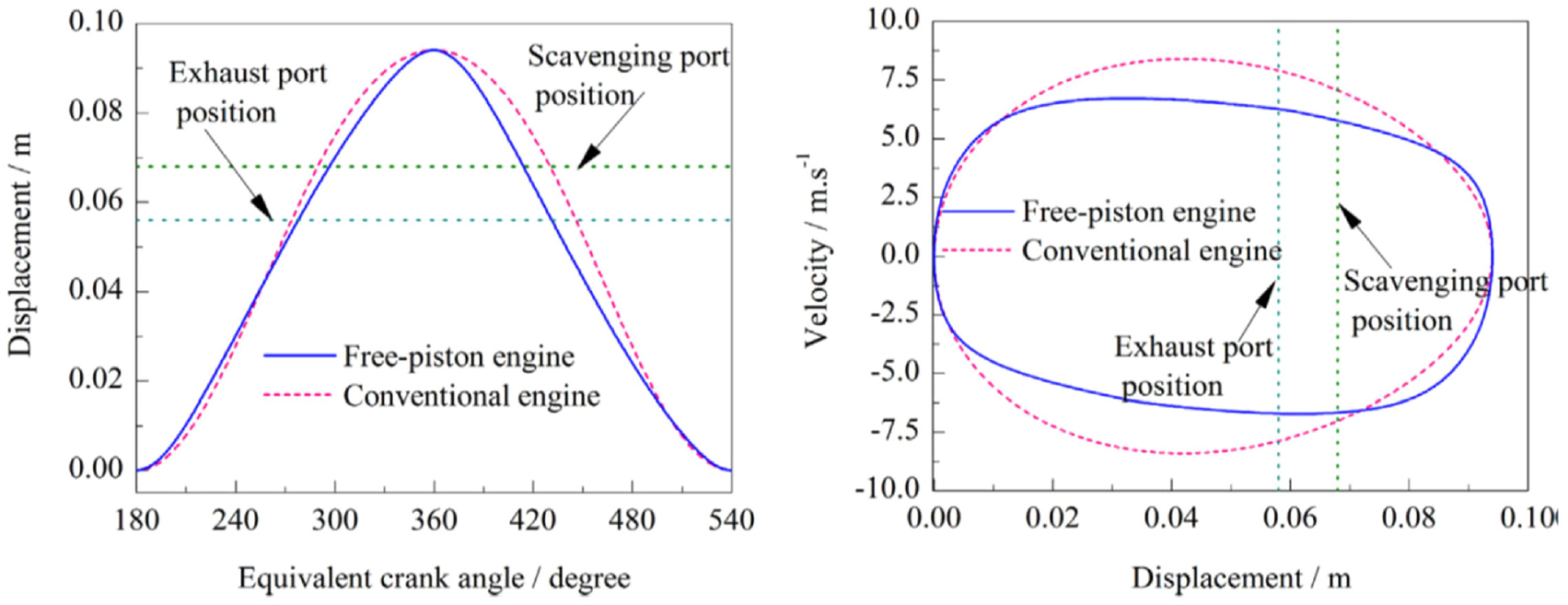
Piston motion comparisons of free-piston engine and conventional engine. 82
Zang et al. 83 evaluated the gas exchange process of a SI loop-scavenged FP-LEG. Higher scavenging and exhaust port height were always favoured to improve scavenging efficiency. In contrast, the optimised angle of tangential and axial inclination of scavenging ports increased with the scavenging efficiency to a stage and decreased subsequently. In addition, a smaller height of scavenging and exhaust ports and tangential inclination was beneficial for increased in-cylinder turbulent kinetic energy, favouring the combustion rate. This suggests a trade-off between improving the scavenging efficiency and the turbulent kinetic energy of the in-cylinder gas. However, the extent of the decrease in turbulent kinetic energy while improving the scavenging efficiency that would adversely affect combustion on FP-LEG is not yet apparent. To increase the trapping efficiency while retaining sufficient residual gas for an HCCI loop-scavenged engine, Sofianopoulos et al. 84 conducted a simulation study of the gas exchange process. Scavenging efficiency of 35% and trapping efficiency of over 98% could be achieved using 1.2 bar air to aid scavenging, and high inclination angles of the scavenge ports. Increasing the scavenging air pressure increased the mass flow rate from the scavenge ports to the combustion cylinder and hindered the start of backflow to the scavenge ports, thereby increasing the scavenging efficiency at the expense of the trapping efficiency.
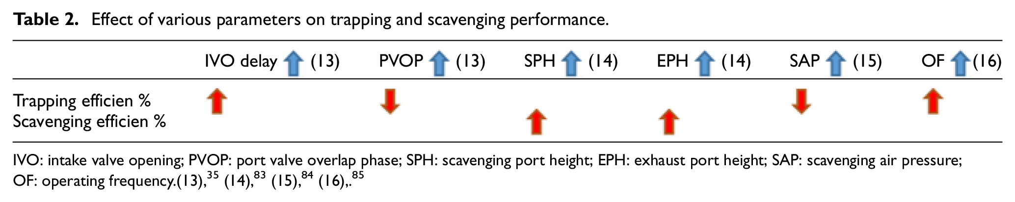
In addition to the design parameters, Hung et al. 85 found that operating frequency also influenced the scavenging performance of a DPP loop-scavenging FP-LEG. The trapping efficiency increased and then decreased with operating efficiency. The initial increase in trapping efficiency was attributed to a longer exhaust port opening duration. The latter decrease resulted from more fresh charge losses through the exhaust because of stronger turbulence in the cylinder. The influence of inlet pressure on the trapping efficiency identified 1.1 bar as the ideal pressure for optimal trapping efficiency. Inlet pressure exceeding 1.1 bar reduced trapped fresh charge due to fresh charge losses through the exhaust (Table 2).
Effect of various parameters on trapping and scavenging performance.
 (13)
(13)Combustion process
Without the mechanical constraints from the crankshaft system, the piston dynamics of FP-LEG is different from the conventional IC engine, which leads to different combustion characteristics. One of the main features of the FP-LEG dynamics is that the piston accelerates and deaccelerates more rapidly and, therefore, spends less time around dead centres than the conventional IC engines. While this feature is beneficial for reducing heat loss and NOx emissions, as the duration of high in-cylinder temperature will be less, it raises a challenge for both combustion and thermal efficiency.
Chinese Academy of Sciences investigated a two-stroke methane-fuelled mini FP-LEG for improved performance. 52 The test setup explored glow plug ignition (GPI) and SI starting modes. The glow plug performs a similar role as the spark plug in the conventional SI engine, and the ignition timing is controlled electronically for the spark plug. In contrast, the ignition timing for the glow plug is related to the state of the mixture. Engine performance and stability improved with the GPI than with the SI because of ignition flexibility in GPI. Too low glow plug heating power (GPHP) resulted in unstable operations, while too high GPHP over-advanced the ignition timing, which reduced the engine CR and flame propagation. In a further study, 51 the circle-to-cycle variation of the in-cylinder pressure and IMEP dropped with adding hydrogen to the methane/air mixture. Improved performance and stability were observed because hydrogen’s wide flammability contributed to the complete combustion of the fuel/air mixture. Indicated power and efficiency of 31.6 W and 10.85% were achieved with a methane/air mixture. With 4% hydrogen addition, indicated power and efficiency were 345 W and 15%. Hydrogen above 4% did not improve performance because it resulted in over-advanced combustion phasing, which degraded combustion and the pressure. Investigation of the engine losses revealed that scavenging losses contributed the most significant of the total loss, followed by the heat transfer loss 53 ; the result is similar to simulation prediction under HCCI. 86
Universiti Teknologi PETRONAS successfully operated a SPP FP-LEG fuelled with CNG and CO2 blend. 55 Combustion and performance improved with advanced injection and rich mixture. The piston velocity during compression was lower than during expansion, suggesting that the bounce chamber would need improvement, and the fuel combustion efficiency was low, about 30%. In order to improve engine performance, the influence of the stroke-to-bore ratio on combustion using hydrogen fuel was examined. 56 Aspect ratio 2.0 favoured higher pressure, heat release, and shorter combustion duration, whereby the ratio of 1.0 produced higher combustion efficiency and frequency.
FP-LEG combustion analysis in SI 87 and CI 88 modes show that the peak heat release rate was low and combustion duration was longer than in conventional IC engines. These are caused by higher piston acceleration around the TDC, which results in less iso-volumetric combustion. In addition, more heat was released in the post-combustion stage, adversely affecting thermal efficiency. Earlier ignition will reduce the post-combustion duration and heat released in the post-combustion stage. The generator control strategy could be targeted to influence the combustion process around the TDC by controlling the piston speed. Therefore, to improve the efficiency of FP-LEG while keeping the merits of less heat loss and emission, it is essential to speed up the combustion process to enable more heat release around the TDC during the expansion process. Several scholars have extensively tried optimising FP-LEG performance through simulation modelling; some results are discussed afterwards.
The influence of ignition timing on piston dynamics and engine performance was investigated by Mikalsen and Roskilly. 89 Guo et al. 90 investigated the influence of injection characteristics on the heat release of a diesel-fuelled FP-LEG. Various injection timing and injection rate profiles were applied. A convex function relationship was obtained between the in-cylinder pressure and injection timing and the CR and injection timing. Consequently, optimum injection timing existed. The influence of different injection rate profiles, that is, rectangle, wedge, trapezium, and triangle, on heat release was compared. The results suggested that the trapezoidal-shaped injection rate profile led to a smooth and iso-volumetric combustion process and was beneficial for the engine’s efficiency.
Investigations in HCCI and premixed charge compression ignition (PCCI) combustion concepts to achieve faster combustion speed and exploit the variable CR benefit of the FP-LEG have been conducted. Kosaka et al. 38 explored PCCI and SI combustion modes using 1-D simulation. With less heat loss and a high degree of the iso-volumetric combustion process, indicated efficiency of 52.7% was achieved with PCCI and higher than 45.4% achieved with SI. Chongqing Jiaotong University conducted modelling studies on hydrogen-fuelled and conventional-fuelled FP-LEGs. A comparison of gasoline-fuelled and hydrogen-fuelled FP-LEG and a conventional IC hydrogen-fuelled engine presented in Yuan et al. 91 indicated that the NO emission of the hydrogen-fuelled FP-LEG was significantly lower than the conventional engine because of lower gas temperature and less time for emissions formation. The influence of other parameters on fuel/air mixing, 92 combustion, and performance 93 of the SI hydrogen-fuelled FP-LEG were examined. A longer stroke was beneficial for achieving a homogenous mixture and lower combustion temperature. Therefore, low NO emission was possible; however, thermal efficiency and power would be compromised. Medium strokes could alleviate the post-combustion late heat-releases influences; nonetheless, they led to more NO emissions due to higher combustion temperature. Combustion efficiency was lower at short strokes, and post-combustion heat release influence was severe due to higher piston velocity around TDC. Diesel/hydrogen-fuelled FP-LEG investigation 94 showed that combustion was enhanced by increased hydrogen addition in the fuel blend.
The assumption of continuous combustion 71 for the JCFP-LEG will benefit the system if it is achieved with the pulsating flows obtainable in the system without many complexities. However, there is a lack of research on the JCFP-LEG preeminent challenges like continuous combustion, pulsating flows, and valve designs. Figure 5 summarises the main areas identified for improved combustion performance of the IC FP-LEG.
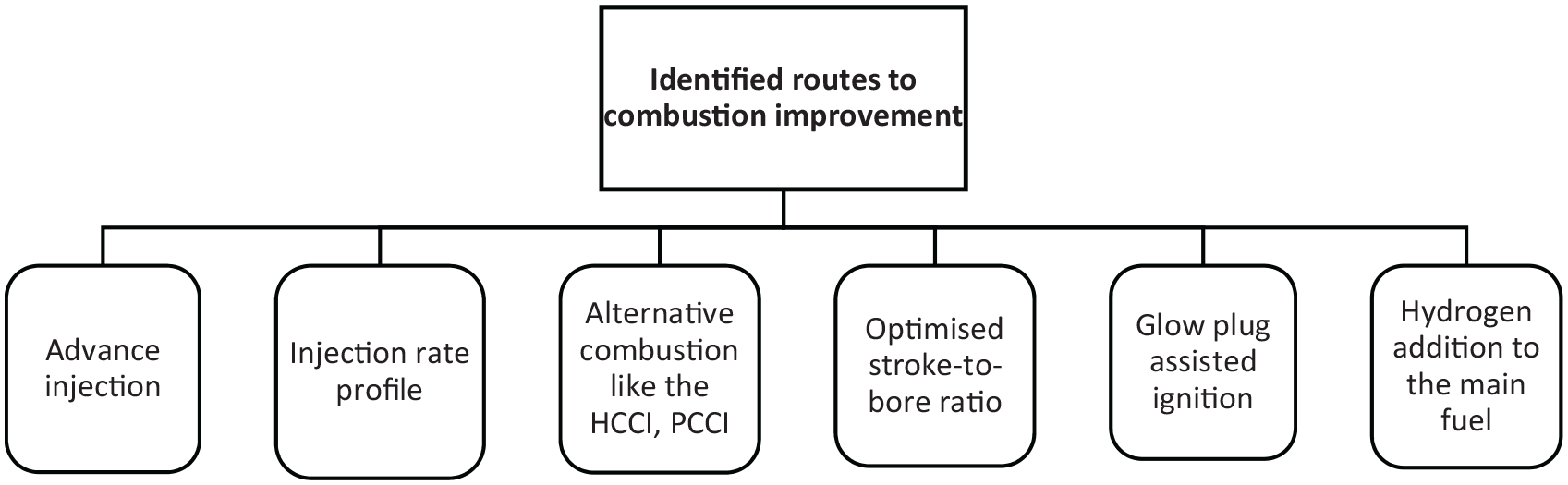
Routes to improved combustion in FP-LEG.
Summary
Despite many FP-LEG test rigs and commercially available, system performance is infrequently reported. However, the available test data supports impressive system efficiency, mainly when HCCI combustion is applied in IC FP-LEG. More data will be helpful to verify the efficiency merits. In addition, engine layout size and weight are rarely reported; thus, the compactness of the FP-LEG is yet to be confirmed. The efforts to improve FP-LEG performance, as indicated in Figure 6, mainly focused on engine configuration, gas exchange and combustion processes. To improve the thermal efficiency of the IC FP-LEG, combustion concepts, such as HCCI, and alternative fuels with higher combustion speed, such as hydrogen, will be required to speed up the combustion process and enable more heat release around TDC during the expansion process.
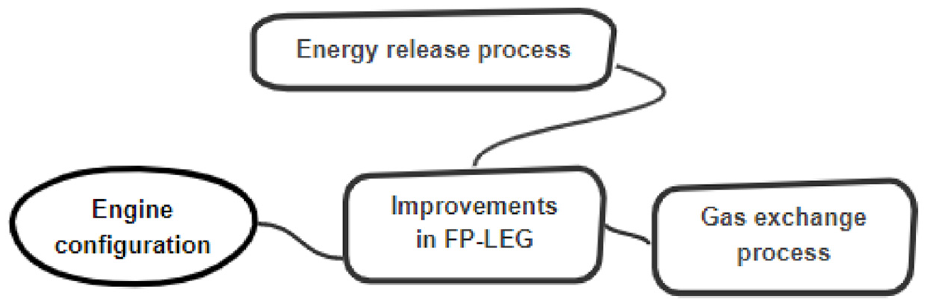
Efforts to improve the FP-LEG.
Advancement of linear generators
The state-of-the-art of linear generators (LGs) for FP-LEG application is presented in this section. The existing LG prototype configurations are categorised into tubular-type and flat-type. The type of the magnetic circuit, mover and winding are listed in Table 3. The analysis and discussion of the main layout configurations from the literature are presented, followed by performance improvement and optimisation.
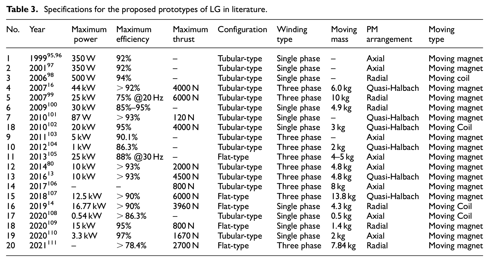
Specifications for the proposed prototypes of LG in literature.
Characteristics and design requirements
The LG in FP-LEG application is an integrated design for motoring/generating operation. During motoring in IC FP-LEG, the LG work as a motor and use electric energy to produce reciprocation motion for a start, stop, and failure recovery. In power generating, LG is used to convert the kinetic energy of the mover to electrical energy. At the same time, fuel mass and electric load are adjusted for a specific frequency, power, and efficiency. An LG is typically coupled to a connecting rod, and the rod is directly attached to FP-LEG’s pistons without any intermediate conversion process. Therefore, the mover of the LG needs to embrace the piston’s high reciprocating frequency and high acceleration.
In rated conditions, the LG does not operate at a constant speed and load, and its performance is a comprehensive effect of the transient process. The design method of the rotary machine based on the constant velocity and load is unsuitable for linear power generation systems. Therefore, LG’s configuration, electric material, permanent magnet, and loss characteristics need to be evaluated based on LG’s operating characteristics. In addition, coupled with the FPE requiring high precision CR control, LG must possess high-precision repeat positioning control of the dead centres. The detent force is the main adverse factor for CR control. In LGs, the detent force includes the cogging force and the end forces that need to be considered. In particular, the testing and evaluation of LG in high acceleration are essential for performance verification.
Layout configurations
The LG layout configuration dominates the selection of electrical material, magnetic circuit, installation method, and performance. For example, the winding type determines the drive circuit control method; the mover type defines the mover mass, reliability, and heat transfer process; the arrangement of permanent magnets (PMs) determines the air-gap magnetic flux density, installation, and output performance. Compared with induction machines and synchronous reluctance machines, a permanent magnet linear generator (PMLG) is evaluated as the best choice considering the efficiency (>90%), power density (>0.5 kW/kg), power factor (>0.9), and a light mover mass. 112 The PMLGs for FP-LEG applications have been extensively investigated in the last three decades. The features and performance are listed in Table 3.
Tubular-type LG
As shown in Table 3, tubular-type LGs are the most widely used. This cylindrical configuration has the feature of radial closure, and thus its leakage flux is small for high power conversion owing to the absence of end windings. Cylindrical shafts of pistons are easily coupled to the LGs. Accordingly, only two cylindrical guide rings are used to support and guide the mover; thus, the installation is relatively simple.
Many improved tubular-type LGs with moving PM have been developed based on the works of West Virginia University95,96 for axial single-phase winding and the University of Sheffield for three-phase winding. 113 Three-phase winding offered a compact structure and high-power density and was among the first considered for FP-LEG application. At the University of Sheffield, a three-phase tubular-type PMLG with 10-poles and 9-slots was designed by Wang et al. 16 as shown in Figure 7. The model for predicting the magnetic field distribution, EMF, thrust force, and armature reaction was established and used to optimise the structural size. 113 The radial, axial, and quasi-Halbach magnetised PM designs were compared and analysed. 113 The segmented PMs with quasi-Halbach magnetisation were employed to ensure the mover is lightweight, and a lightweight titanium alloy with non-magnetic was used as structural support. The stator was assembled by a modular I-shaped stator core and stator windings to develop a prototype with a long mover and a short stator. The results indicated that the prototype provided a maximum thrust of 4000 N, a mover mass of 6.0 kg, and a thrust force constant of 13.28 N/A. With a pulse width modulation switching frequency of 8 kHz, a peak efficiency of 92% was achieved.
A prototype of 10-poles and 9-slots tubular-type LG: (a) schematic diagram of LG and (b) moving-magnet mover assembly of prototype. 16
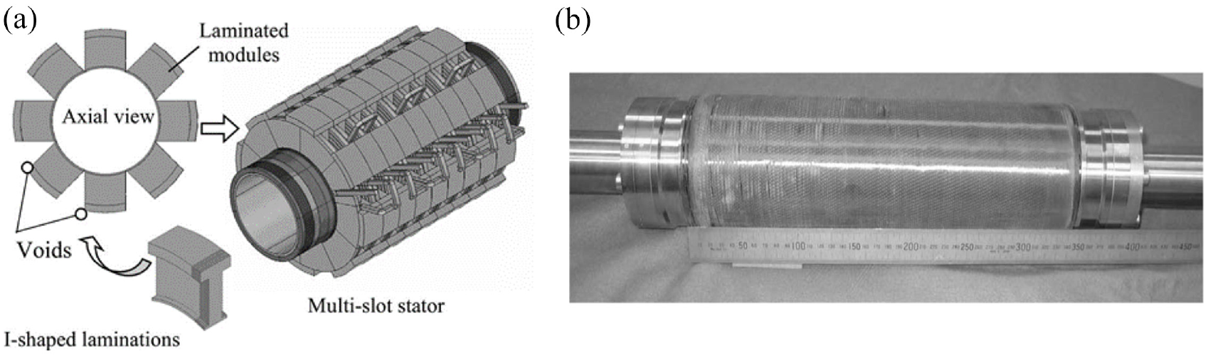
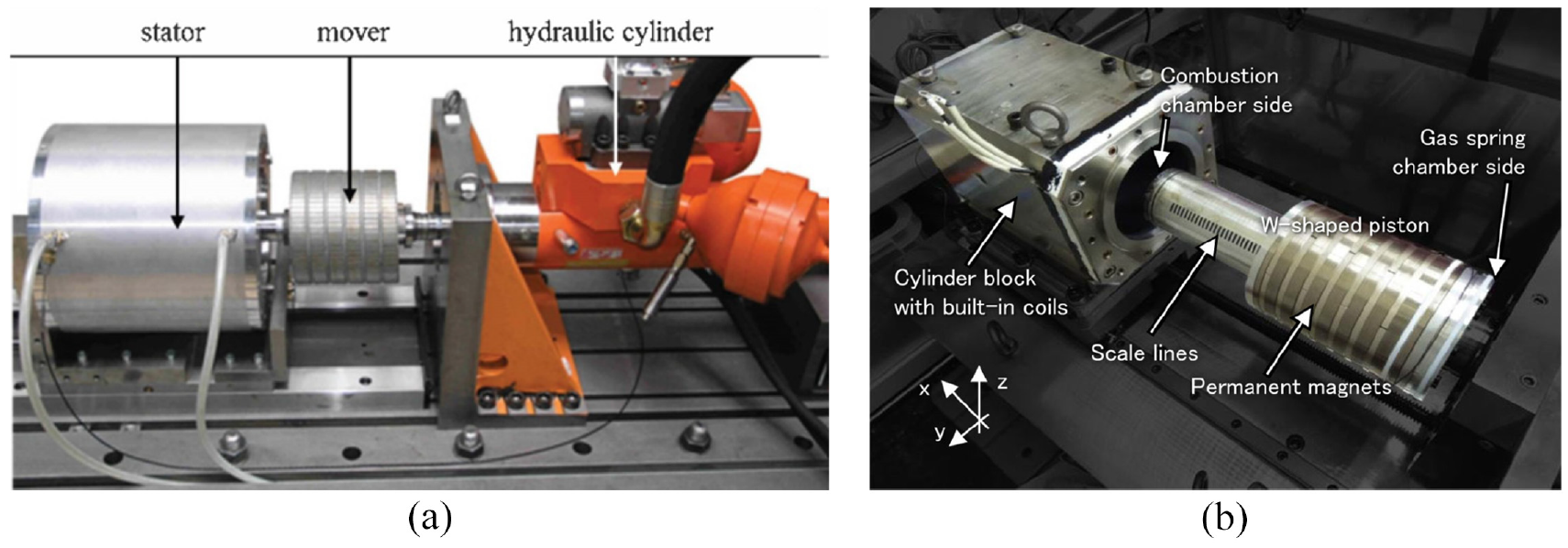
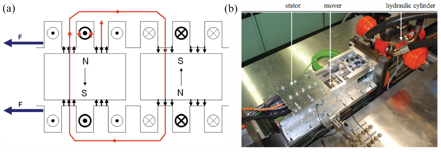
In DLR, flat wires were used to obtain high space utilisation and good thermal conductivity, and this technology reduced the machine size by 33%.99,114 An axial iron laminated along the circumferential direction for low eddy current loss was used. To reduce the mover mass, the mover was restricted to effective length only; therefore, the actual stator length was the total of the effective and stroke length of the mover, as shown in Figure 8(a). The cooling device was also designed to remove heat from the stator windings. A thrust constant of 33 N/A and 6000 N peak thrust was achieved. In Toyota Central R&D Labs Inc., a W-shaped piston was adopted to reduce the demagnetisation of PMs caused by high temperature to increase the heat transfer path away from the combustion chamber, 80 as shown in Figure 8(b). The prototype achieved a maximum thrust force of 2000 N under seven coils and four pairs of PMs.
Aiming to ensure a low iron loss in tubular-type LGs, the direction of the circumferential stacking stator is made parallel to the magnetic flux of the PMs. Compared with the axial stacking stator, this measure greatly reduces the eddy current loss in the stator iron core. However, the stacking coefficient of silicon steel is low and affects the performance of the LG. Therefore, some advanced technologies and novel materials have been proposed to overcome this adverse factor.
Jalal et al. 106 from Newcastle University utilised a Soft Magnetic Composite (SMC) with high resistivity to build the stator core back. The windings were sandwiched between them to form a compact stator, as shown in Figure 9. In addition, SMC was used on the mover as the iron poles with axial magnetised PMs. A non-magnetic tube was used as the supporting tube to reduce the mover mass. In Figure 10, a novel tubular staggered-tooth transverse-flux PMLG was proposed by Zheng et al. 17 at Harbin Institute of Technology. The structure allowed the stator iron core to be stacked along the axial direction, which improved the stacking coefficient of silicon steel and simplified the installation procedure. However, the magnetic circuit of the transverse-flux machine was required to be analysed by a 3-D simulation model. Therefore, it is challenging to be optimised for high power factors. Besides, the manufacture of the iron core would be a complex process.
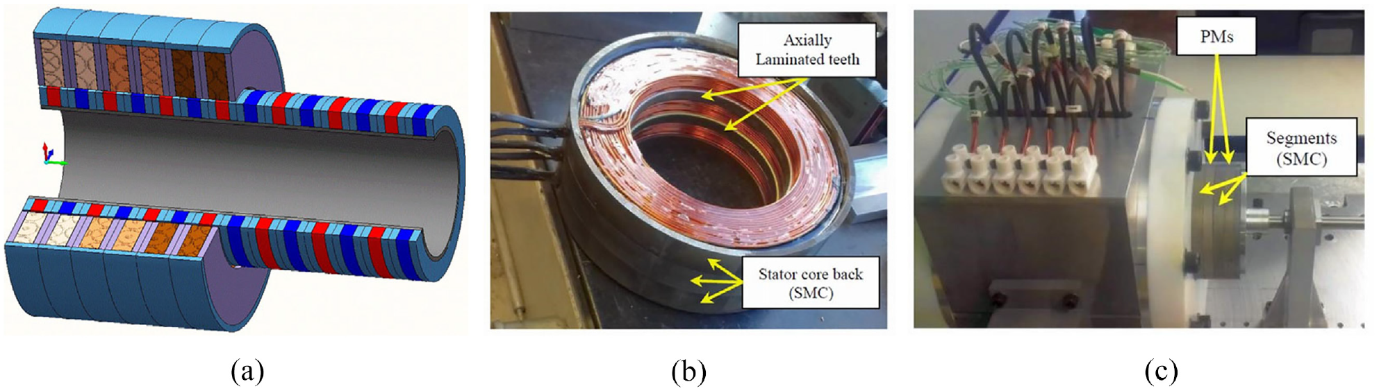
LG in Newcastle University: (a) schematic diagram, (b) stator module, and (c) prototype. 106
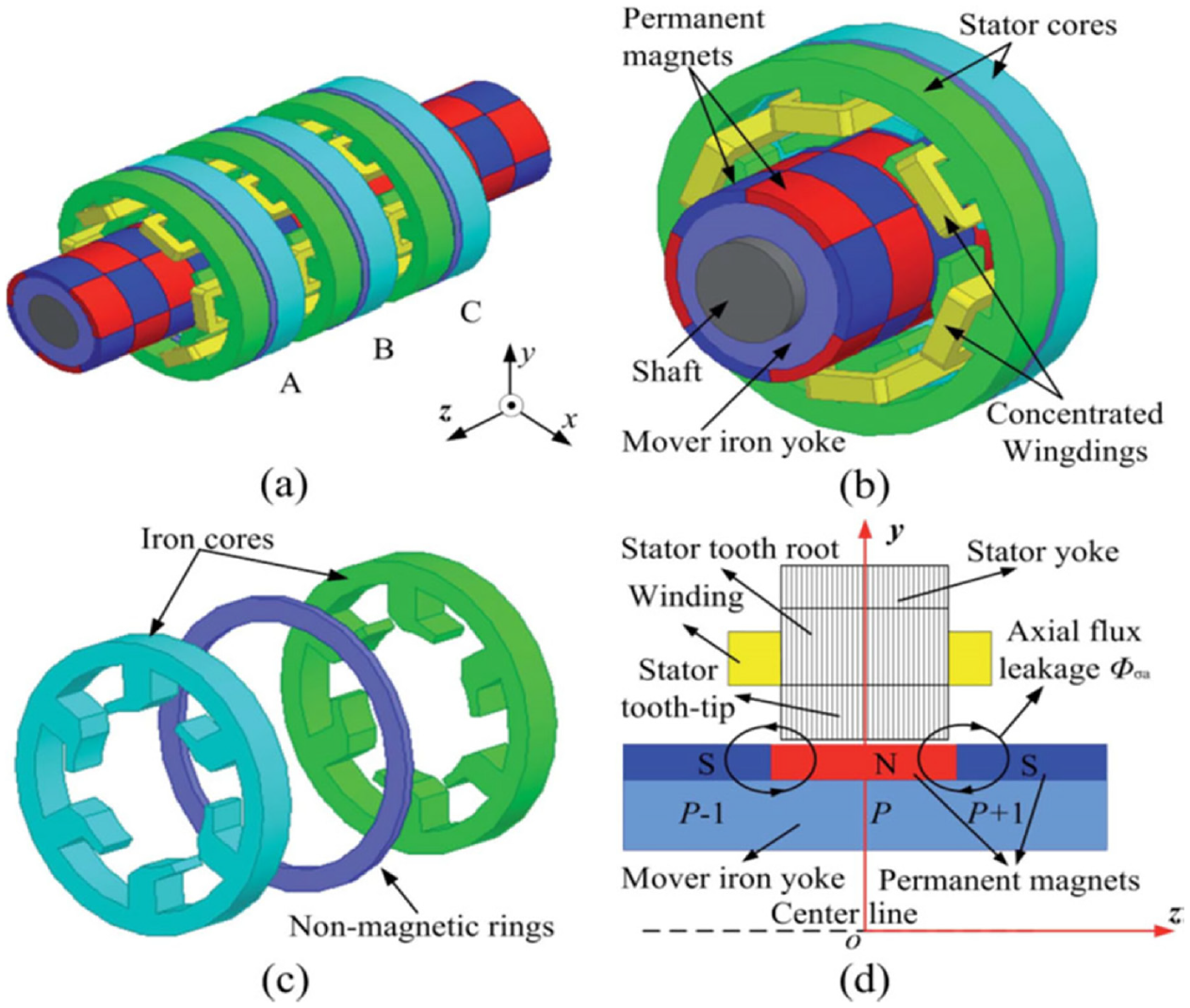
Structure of LG in Harbin institute of Technology: (a) overall structure, (b) one phase of machine, (c) stator cores and nonmagnetic ring, and (d) side view of machine with one stator core. 17
The already discussed tubular-type LGs were designed for the three-phase application. To simplify the driver circuit and the complex design of the magnetic circuits, some tubular-type LGs with single-phase windings were also investigated.
In SNL, a tubular-type multi-windings LG with a stroke of 200 mm was developed for the opposed-piston type FP-LEG. 100 The stator body comprised an array of 14 coil-and-bonded-iron-core units, and the pole pitch is 22 mm, as shown in Figure 11. The mirror image coils from LGs, on the left and right sides, were connected to the same resistor in the actual operation. The estimated efficiency was around 85%–95%. In Sun, et al. 110 a tubular-type single-phase LG with axial magnetised PMs was proposed, as shown in Figure 13(c), a peak efficiency of 91% was obtained at 50 Hz.
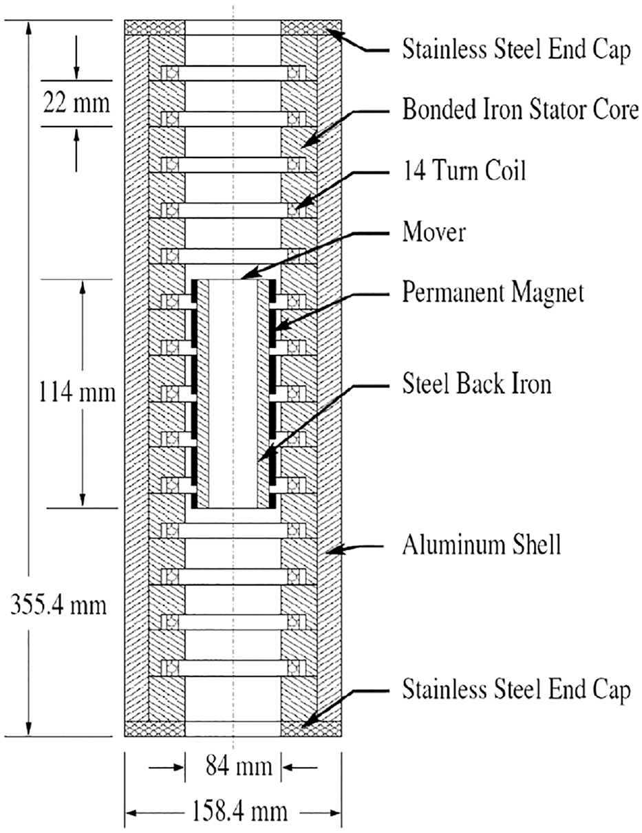
Structure of the Magnequench LG. 100
The LGs with moving coils are popular in some small power generation systems due to their simple installation. The high amplitude-alternating magnetic field caused by moving PMs is eliminated. Low iron loss, low eddy current loss of PM, and high efficiency manifest at high frequencies and low loads. In Annen et al. 98 a single-pole/phase tubular LG was presented by Aerodyne Research, Inc., as shown in Figure 12. At 150 Hz, the power output of 500 W was achieved, and the highest operation current reached 3.5 A. Nanjing University of Science and Technology team proposed a series of tubular-type LGs with single-phase winding. In 2010, a moving coil LG equipped with quasi-Halbach PMs was proposed, as shown in Figure 13(a). The thrust force density of 463 kN/m3 and 4000 N thrust was achieved. The finite element method (FEM) conversion efficiency was 95% in the low speed and light load regions. Similarly, a novel tubular type LG with radial-magnetised PMs was developed, 14 as shown in Figure 13(b). The average thrust, thrust coefficient and current achieved were 3960 N, 33 N/A, and 120 A, respectively.
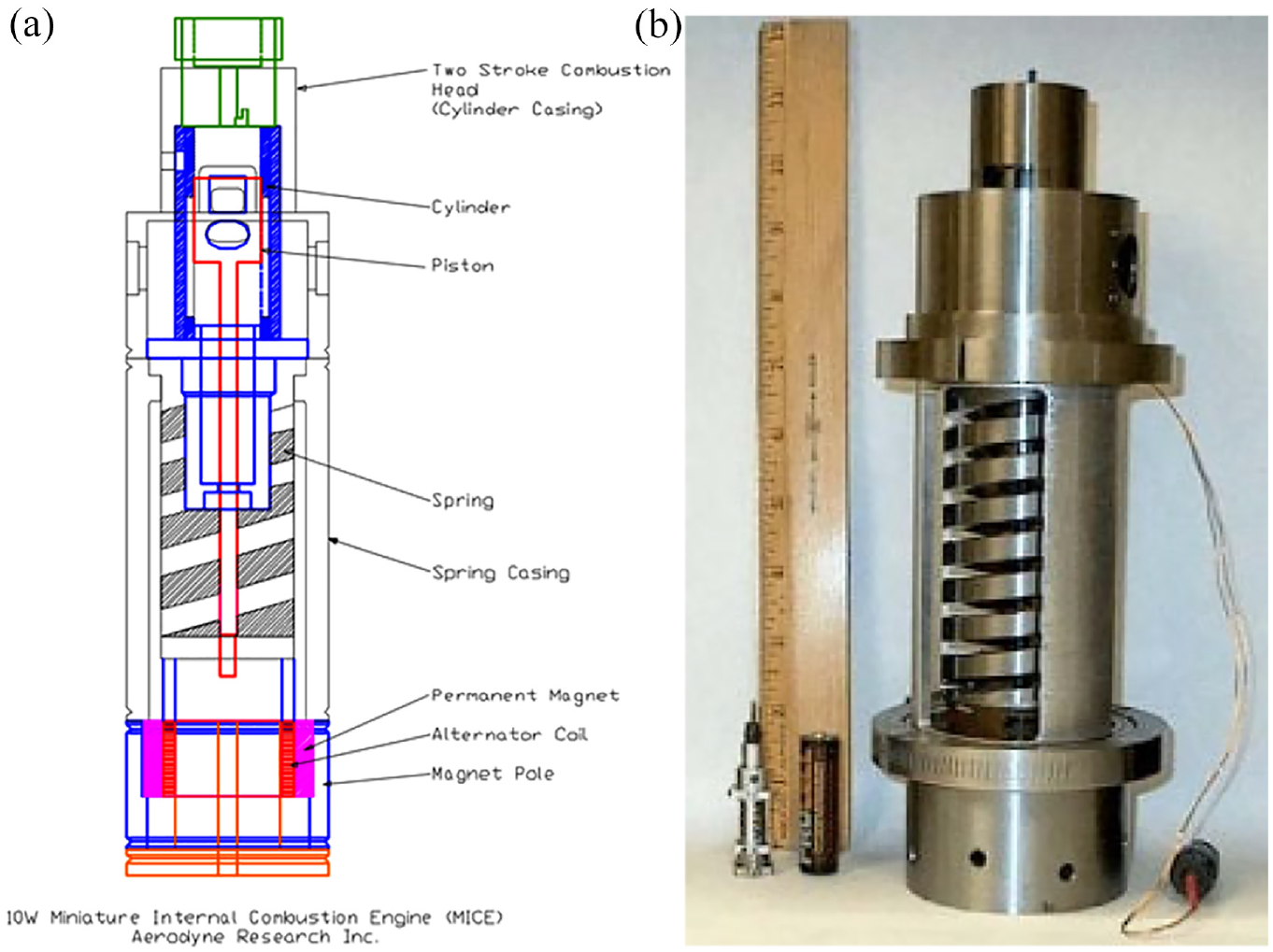
LG in Aerodyne Research, Inc.: (a) structure of LG and (b) prototype of LG. 98
Flat-type LG
The flat-type LG parts tolerate low machining precision, and their manufacturing process is simpler than the tubular-type LG. The high transverse laminated factor and low iron loss of silicon steel iron core can be easily achieved because the plane of the magnetic circuit is parallel with the stacking direction of silicon steel.
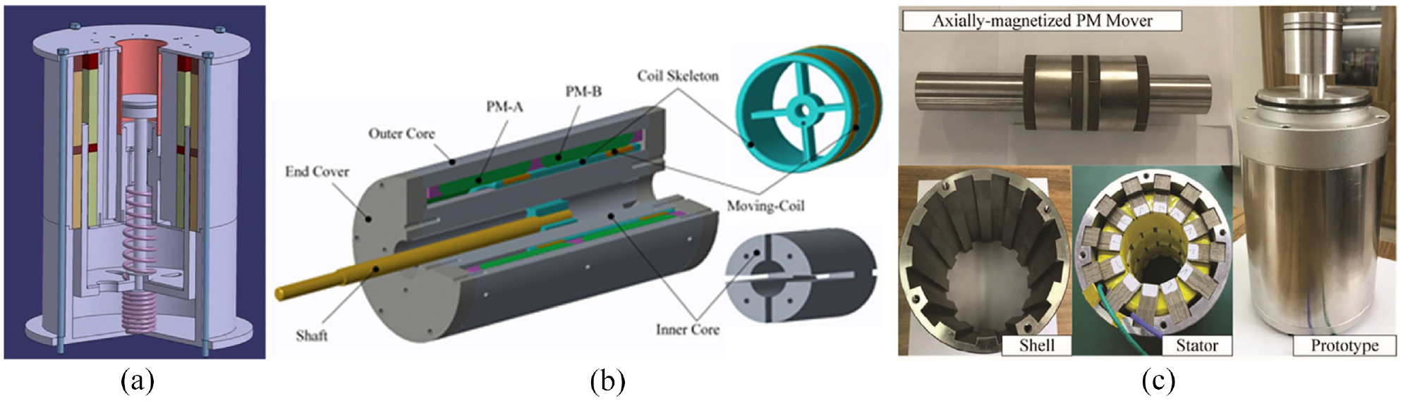
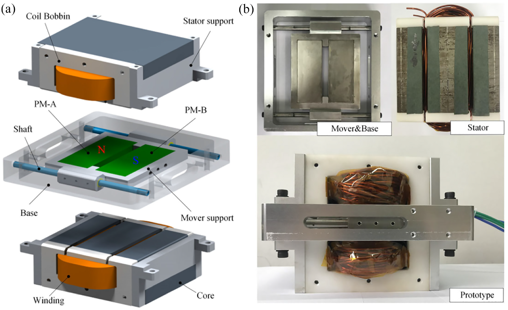
Li et al. 115 from Shanghai Jiao Tong University compared the flat-type and tubular-type LGs. The simulation results indicated that the flat-type LG had a higher output power and efficiency at specific external loads. The proposed LG had double-sided stators, and the attraction force acting on the mover was eliminated to achieve low friction. This structure provides a low mover mass for high acceleration. Subsequently, some flat-type LGs had been proposed for FP-LEG. In DLR, F. Rinderknecht 105 suggested that the required frequencies of 50 Hz and mover mass of 4–5 kg could not be met by using the tubular-type LG with the magnetic back iron. Therefore, the PM arrangement without an iron core was proposed to attain high power density and required efficiency, as shown in Figure 14(a). This topology reduced the mover mass and losses in the LG. A similar LG with a single-phase was proposed; see Figure 15. This prototype had a low mover mass of 1.4 kg, an output power of 2 kW, and an efficiency of 95%. 109 In the last two prototypes discussed, PM was used as the supporting material; therefore, the mover’s structural strength should be further analysed. The Chinese Academy of Sciences presented the double-side quasi-Halbach arranged PMs for high air-gap magnetic flux density.15,107 With this magnetic circuit, a lightweight and non-magnetic material can be used as the supporting plate for a lower mass mover and higher power density, see Figure 16.
A plat-type LG in DLR: (a) electrical flux line of LG and (b) prototype of LG. 105
A plate moving-magnet LG in Nanjing University of Science and Technology: (a) 3-D structure of LG and (b) prototype of LG. 109
A double-sided flat-type permanent magnet PM in University of Chinese Academy of Sciences: (a) 3-D structure of LG and (b) prototype of LG. 15
The previously discussed LGs have unequal length mover and stator, and the redundant PMs or windings are required for constant thrust and an effective stroke. Therefore, the mover mass or the copper loss is increased. In Otto von Guericke University Magdeburg, the combination of 5-poles and 6-slots was implemented, and an equal length stator and mover flat-type LG was proposed (see Figure 17). 116 Based on FEM results, a low mover mass and high efficiency can be achieved. Using a similar length structure, the end effect caused by the finite length of the mover/stator produced the thrust fluctuation and inductance variation, affecting the operation’s stability and maximum efficiency. An improved thrust force control method was proposed for a finite length LG based on the adapted transformation. 117 A prototype was proposed and tested at a frequency of 24 Hz with the desired stroke of 30 mm. The peak force of 3760 N was achieved, and an efficiency of 78.4% was achieved with an optimised spring.111,117
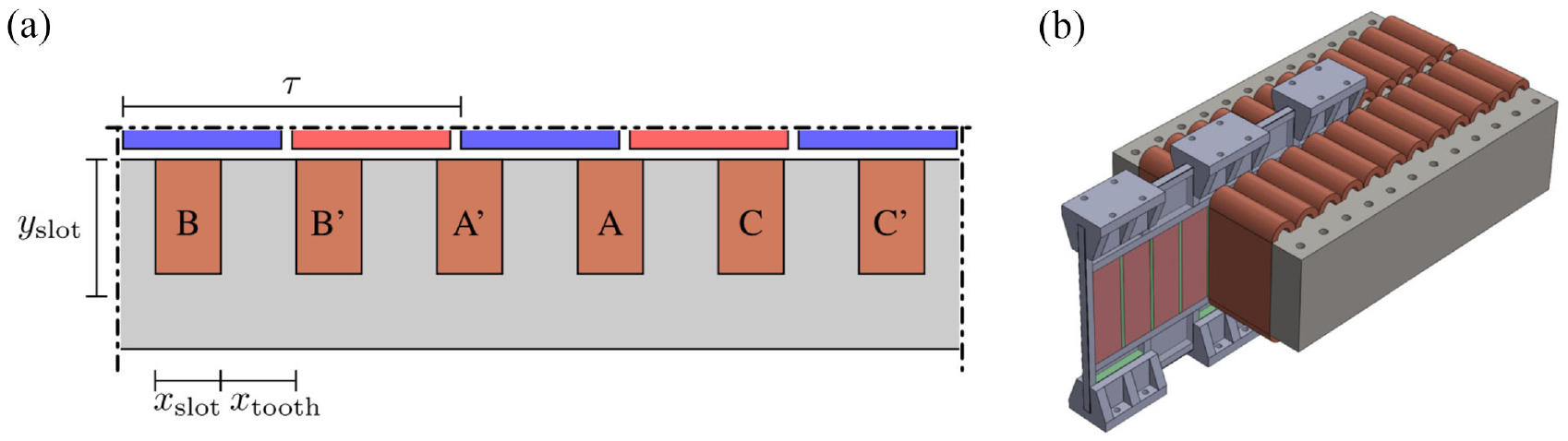
A LG in in Otto von Guericke University Magdeburg: (a) simulated section of the flat-type linear machine and(b) concept drawing for the construction of LG. 116
Performance improvement and evaluation
Improving conversion efficiency and power density are often the goals of a power conversion device, such as FP-LEGs. The existence of the cogging force in LGs affects precise control and dynamic response of FPE, thereby requiring further considerations. The LG performance indicators are usually used as the optimisation objectives, which will be discussed in this section. After the design stage, the performance of optimised prototypes would be tested and evaluated by employing a device capable of performing the reciprocating motion, which may cause potential limitations in evaluating LGs’ performance. This will also be discussed in this section.
Efficiency and power
LG works in transient conditions with continuous acceleration or deceleration, which is very different from conventional rotatory machines. The efficiency is calculated from energy conversion over a reciprocating motion cycle. The efficiency of an LG in a cycle depends on the loss distribution in different velocities and load currents. The following two approaches were generally adopted in the literature for efficiency optimisation. The first is to select an appropriate process, material, and structural parameters to decrease motor loss. The key design considerations incorporate magnetic pole partition for reducing eddy current loss, 105 flat wire winding for reducing copper loss, 13 and high-grade silicon steel sheet for reducing iron loss. To optimise the structural parameters, J. Wang and Howe proposed an analytical expression for the performance in LG.113,118 With this analytical model, the efficiency was optimised by adjusting three critical dimensional ratios: the ratio of the PM outer radius and the stator outer radius; the ratio of the pole pitch and the stator outer radius; the ratio of the magnetised PM radial length and the pole pitch. 16 Similarly, a transverse-flux PM LG was optimised by adjusting these three ratios based on the 3-D equivalent magnetic circuit model. 17 Only the highest efficiency was concerned in these studies, while the efficiency in a reciprocating cycle would be a more practical indicator.
For a given LG, it is also an effective method to optimise the mover’s motion profile, primarily determined by the generating-braking force and their combined effect in a reciprocating cycle. The transient efficiency of an LG will be optimised if an optimal motion profile is achieved, which, in turn, results in the best efficiency of energy conversion in a cycle. Considering the transient working conditions of LGs, Sun et al. 110 proposed an optimisation method for efficiency based on the velocity and current with a sine-curve in a stroke of 36 mm and a frequency of 50 Hz. Using FEM, the mover mass of LG was optimised. Similarly, Benecke, Gerlach, and Leidhold proposed an approach for minimising power loss to achieve high efficiency under acceleration and deceleration conditions. 116 An analytical losses model was developed based on the unique periodic trajectory. The iron and copper loss were evaluated, and the total loss was minimised. The optimisation algorithm is presented in Figure 18. 116 Using the tracked trajectory, such as a sinusoidal function in optimisation studies, the researchers noticed the large generating-braking forces at dead centres, which indicates LGs must resist rapidly rising cylinder pressure in FP-LEG application. In Wang et al. 101 a comprehensive methodology of a generating-braking modulation method was proposed to achieve the best transient efficiency distribution and the optimal energy conversion efficiency. This approach reduced the power generation loss by 50% and improved energy conversion efficiency by 0.9%.
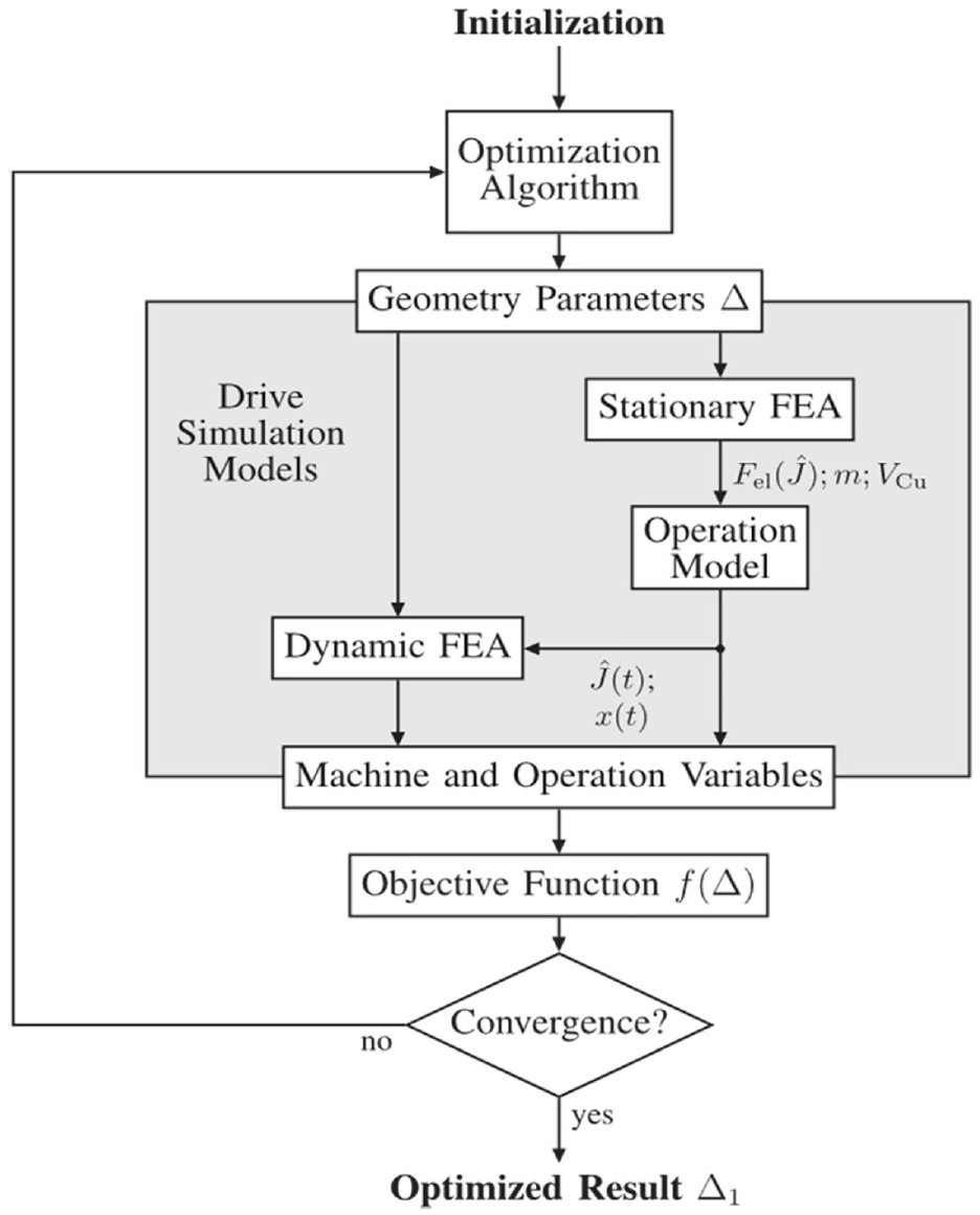
Optimisation algorithm with drive system simulation. 116
Typically, for low mover mass, some lightweight, non-conductive materials, such as aluminium alloy, 15 titanium alloy, 113 carbon fibre, and glass fibre, 14 were used to support the mover, therefore allowing higher frequency and shorter cycle time. The material consideration of movers is always associated with the motion control at the dead centres, where a lighter mover with a swift change of velocity direction would always benefit the efficiency. In Poltschak and Ebetshuber 119 an integrated magnetic spring was proposed by adding the auxiliary end PM ring and ferromagnetic steel. Benecke 116 proposed an LG whose mover length equals the mover, and the end forces were enhanced. The design provided significant acceleration at the dead centres. Apart from adjusting structural parameters and motion profiles, cooling system addition is also necessary to improve power output. In Rinderknecht 105 a cooling system was integrated and thus improved the rated thrust. Because of the cooling system design, the stiffness and oscillation frequency of the LG was considered. The mover mass was optimised to be minimum. The end effects caused by the finite mover and stators at the dead centres are used as the magnetic springs (high system stiffness) to improve the stiffness for high oscillation frequency.
Detent force
In FP-LEG applications, the control precision of dead centres depends on the repeating positioning precision. The detent force caused by cogging and end forces is an important factor affecting the smooth operation of LGs. The slotted stator creates the cogging force, and the universal reduction methods include skewing PM, optimising structure size, and adjusting pole/slot combination. A suitable stator length, chamfering and auxiliary poles are often implemented to reduce the end force.
The opening of the slot tip and axial length of the end tooth were optimised to reduce the detent force in a 7-pole/6-slot PM LG with a long mover. 104 However, the reduction of detent force using this measure was limited. The detent force of 106 N remained for a 1 kW tubular-type LG. An analytic model combining the slot-less magnetic flux and permeance function was presented to adjust the structural parameters to reduce the detent force. 120 The amplitude of detent force less than 2 N was obtained from the FEM results. The detent forces of two different ferromagnetic materials for the stator core, containing silicon steel laminations and Somaloy, were compared and analysed. 121 Using Somaloy produced a positive effect in reducing the detent force, and the back-EMF had an apparent increase. In Jalal, 122 adding flux gathering rings at both ends of stators was presented to reduce the end effects. The rated force ripple of 10.6% was obtained with this strategy based on the FEM results. Interestingly, the smooth operation in the FP-LEG with reduced cogging force minimised the losses and saved almost 7.1 J per mechanical cycle. Some high-precision analytical reduction techniques of detent force for the precision linear motor also could be applied to the LGs.19,123,124
Test benches and performance evaluation
The performance evaluation of LGs involves testing some of its basic electric parameters under static and various dynamic conditions. The parameters tested under static conditions include the resistance, inductance and thrust constant. The back-EMF constant, power output and conversion efficiency are tested under dynamic conditions. The equipment used to test the rotary motor typically is useable to evaluate LGs for static performance. However, dynamic testing platforms are not standard equipment for LGs. Different types of reciprocating motion test benches can be found in the literature: linear motor-driven platform, 101 rotary motor-driven platform, 15 and air cylinder-driven platform. 100
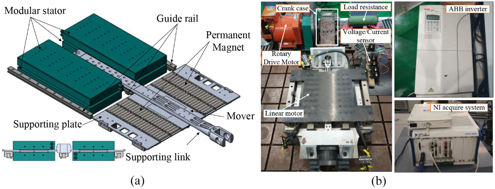
A programmable track provided by a linear motor can drive a LG prototype for dynamic parameter testing on the linear motor-driven platform. 101 Usually, a tension pressure sensor is installed between the connecting shaft of two motors. The input power, the product of thrust and velocity, is measured, and the output electric power from the load is obtained. It is worth noting that there is a delay between the real thrust and the measured thrust data from the load cell with the strain gauge principle at high acceleration and high frequency working conditions. Thus, a sensor based on the piezoelectric effect must be used for accurate measurement, which is usually costly. Similarly, the rotary motor-driven platform comprises a rotary motor and crankshaft connecting rod. It thus produces reciprocating motion to drive a LG prototype 15 to measure the parameters in interests under different frequencies. In such a testing platform, the motion profile depends on the kinematics of connecting rod and cannot be adjusted. The linear motion also could be different from the rated condition of the LG in a test.
The test platforms stated earlier are relatively complex to achieve at frequencies greater than 50 Hz. The main reason is that the test platforms at dead centres cannot provide large deceleration/acceleration forces, which is associated with the limitations on mechanical strength. Some auxiliary energy storage devices, such as air-driven or spring-driven platforms, offer higher acceleration at the dead centres. The high-frequency operation was realised if a careful matching exercise had been conducted in terms of mass and stiffness of the testing platform and the LG in the test.100,125
Summary
The performance of various LG configurations in the recent literature was discussed in the section. The tubular-type LG is a popular topological structure with a compact size; it provides convenience for the guide sliding structure, although with a complex stator structure and assembling process. The flat-type LG simplifies the stacking of silicon steel sheets and has a low iron core loss, although relatively complex guide rail installation is required. The design, optimisation, and performance evaluation of LGs operating in a reciprocating motion have a noticeable difference from conventional rotatory machines. The transient process must optimise during a reciprocating cycle to achieve the best cycle performance. Therefore, considering the overall characteristics of FP-LEG dynamics is vital to optimising LG performance and efficiency.
Control strategies of FP-LEG systems
Piston movement between the dead centres must be adequately controlled to achieve a stable and high-performance FP-LEG operation. Effective control of FP-LEGs is essential and identified as one of the major challenges to realising flexible and stable FP-LEG operation. This is because transient forces acting on the mover determine the piston dynamics, which are affected by instantaneous conditions and cycle variations caused by in-cylinder pressure and LG’s load changes. The main FP-LEG control route includes the piston motion trajectory tracking, where piston motion is controlled to follow a predetermined motion profile50,126,127 and output current with a predetermined reference current profile,20,128 and through combustion and load balance, where the combustion parameters are: ignition time, fuel mass, air-fuel ratio, and compression ratio.129,130 System control is required for both starting process and stable operation control to fully optimise the operation and utilise the operational flexibility of FP-LEGs. This section discusses the FP-LEG starting and stable operation control strategies.
Starting process control
The starting process of the JCFP-LEG and opposed-piston FP-LEGs could be achieved by using an external compressor/vessel to supply compressed working fluid to the expander until a stable operation is achieved. In most JCFP-LEG applications, the external supply is terminated at stable operation, and the FP-LEG compressor subsequently supplies the working fluid. 70 For the IC FP-LEG, two main methods are used: compressed gas or/and the linear alternator as the starter. The compressed gas starting uses an external high-pressure air source to drive the piston to achieve the target compression ratio. Two methods for starting with the linear alternator are one-stroke starting and resonance starting. With the one-stroke starting method, the thrust generated by the linear alternator in motor mode must be large enough to overcome the compressed air force to reach the CR appropriate for ignition. However, considering the typical linear motor constant and coil’s current capacity, an oversized linear alternator would be needed to generate enough thrust for the one-stroke starting. It could result in a mismatch in sizes between the engine and alternator and minimal output generated from the engine, which is not useful in applications.131,132 In the resonance starting method, the alternator works in motoring mode and drives the mover to multiple strokes. Suppose the motoring force is large enough to overcome the losses due to friction, heat dissipation, and gas leakage. The maximum kinetic energy of the mover will be increased until the air is compressed within the combustion chamber to reach appropriate ignition pressure. A much lower motoring force is required with this method than in the one-stroke method. The resonance starting method has proven effective both in simulation and experiment. 133
While most studies on the FP-LEG starting process share the same objective to enable a swift, smooth, and efficient start-up, various optimisation methods of control have been investigated. The various methods of control are discussed hereafter.
In the resonance starting process, the direction of the motor force should be adequately reversed to obtain an appropriate piston swing motion, dependent on the control technique adopted for the reversing. The control input for motoring force reversing is based on either piston position or the sign of piston velocity. Accordingly, Sun et al. 134 proposed the position-tracking and velocity-tracking modes for the resonance starting and compared both modes on a dual-piston FP-LEG configuration. The position-tracking mode has two pre-set position points towards the ends of strokes, where motor force reversing would happen. Motor force may go against the mover direction in this mode, thereby producing negative work. The negative work would lead to a penalty in starting efficiency, defined as the ratio of positive work to total work by the motoring force. Motor force reversing occurs when the mover velocity direction change is anticipated in the velocity-tracking mode. Due to the indirect velocity measurement method, slow response and measurement errors may affect the reliability and stability of the control method. To improve the position tracking method, a gradually increasing reversing position strategy is preferred to reduce the negative work by the starting force. As a result, the optimised position-tracking mode, which has satisfactory efficiency and operability, was recommended. The position-tracking method is preferred in estimating the TDC for other FP-LEG control applications.135,136
Some opposed-piston FP-LEGs use an external high-pressure gas source to drive the piston and achieve the target CR in one stroke. 45 To avoid using supercharging equipment during the starting process, which could be complex. Wu et al. 137 proposed a resonance starting method for the opposed-piston FP-LEG with the two linear electric machines operating as linear motors and utilising a synchronisation mechanism. Maintaining synchronous operation of the opposed pistons during starting process is challenging. Therefore, the displacement master-slave control and current master-slave control strategies were proposed. Test results confirm that both control strategies are feasible to start the FP-LEG, and the current master-slave strategy produced a quicker response to external interference. Consequently, the piston synchronisation error is lesser. Secondly, the current master-slave control strategy requires a lesser motor force to attain the target peak in-cylinder pressure and continuously produce positive work on the piston compared with the displacement master-slave control strategy.
There are failed attempts to use open-loop control methods to achieve ignition in IC FP-LEG. Zulkifli et al.132,138 conducted a modelling study on an open-loop control strategy by energising the coils with a fixed DC voltage and rectangular commutation of injected current. Several initial motor forces were applied, but none successfully achieved the required CR for ignition. Results of the investigation of open-loop and closed-loop control strategies for the FP-LEG starting process were presented in Jia et al. 20 In the open-loop control strategy, it was expected that with a fixed initial voltage on the stator, a sufficient and constant motor force would be produced, and the displacement amplitude and peak in-cylinder pressure would grow gradually to the required level. However, this trend did not manifest. The piston displacement amplitude quickly reached a steady but low level, corresponding to a CR of 1.4:1 and was far from the ignition. In addition, as shown in Figure 19, the CR increased with the injected current. However, the CR was not enough even with the rated current. A further investigation showed that the back electromagnetic voltage resulting from the mover’s motion, as indicated in Figure 20, influenced the motor output force. With the unsatisfactory performance of the open-loop control strategy, a closed-loop control strategy was investigated. Compensators were applied to reduce the influence of back electromagnetic voltage. With the current as feedback, the injected current to the coil is adjusted to maintain the motor force at the target value. As shown in Figure 21, piston displacement and velocity amplitudes grew gradually, as expected with the closed-loop control strategy.
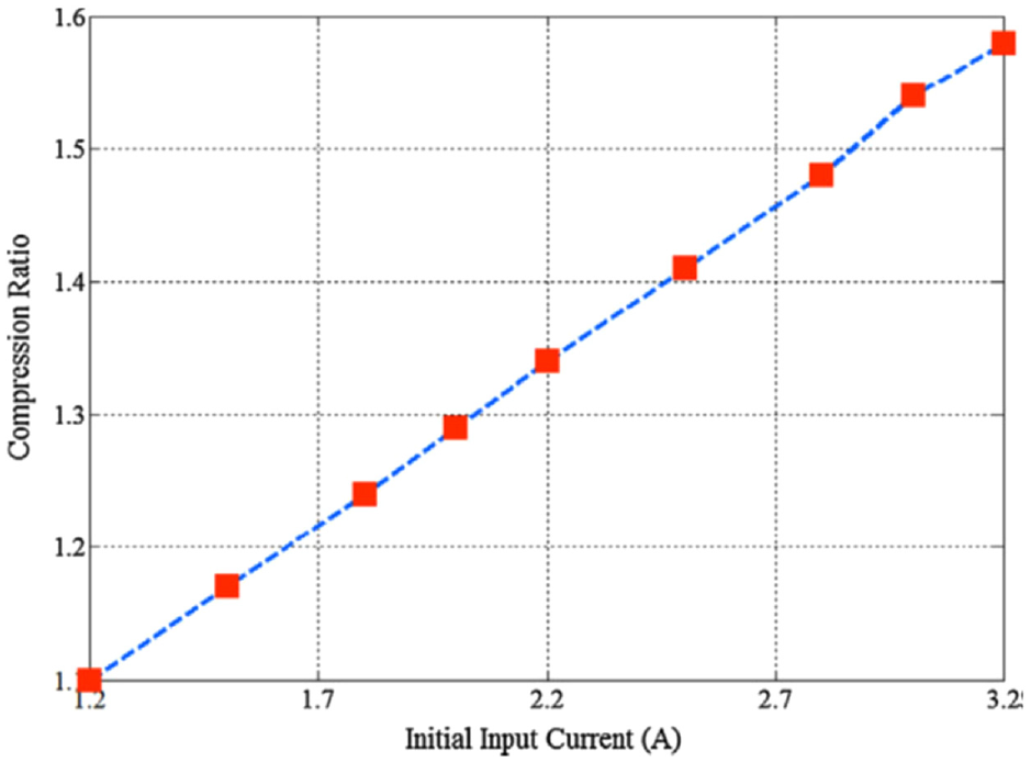
Compression ratio with different initial inject currents. 20
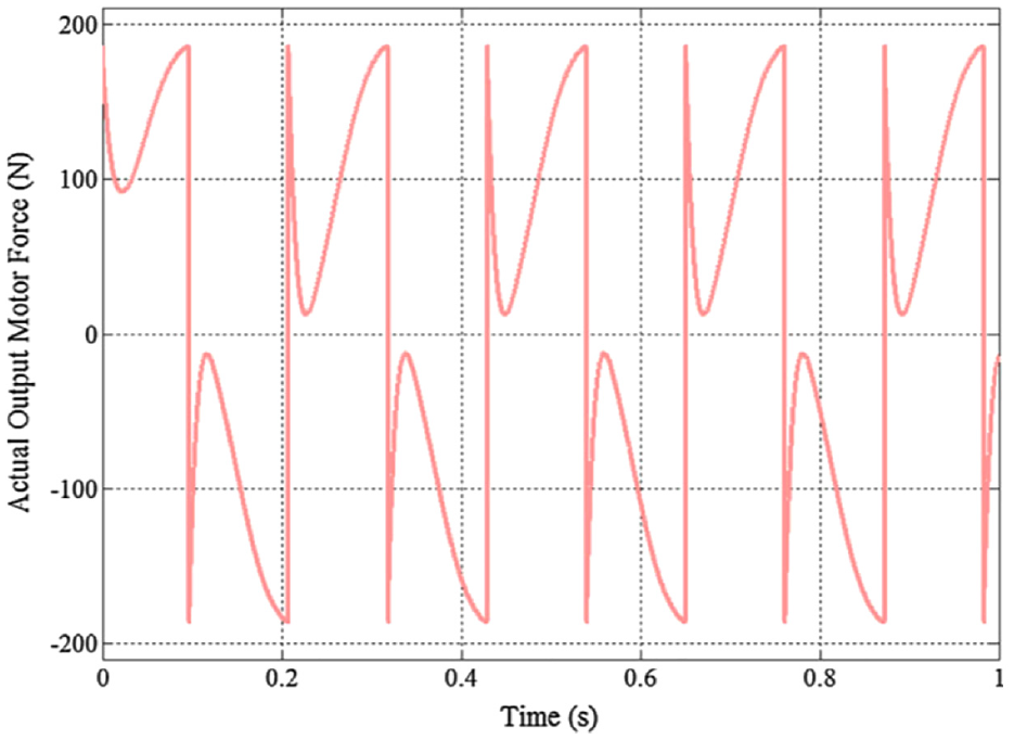
Actual output motor force versus time for open-loop control. 20
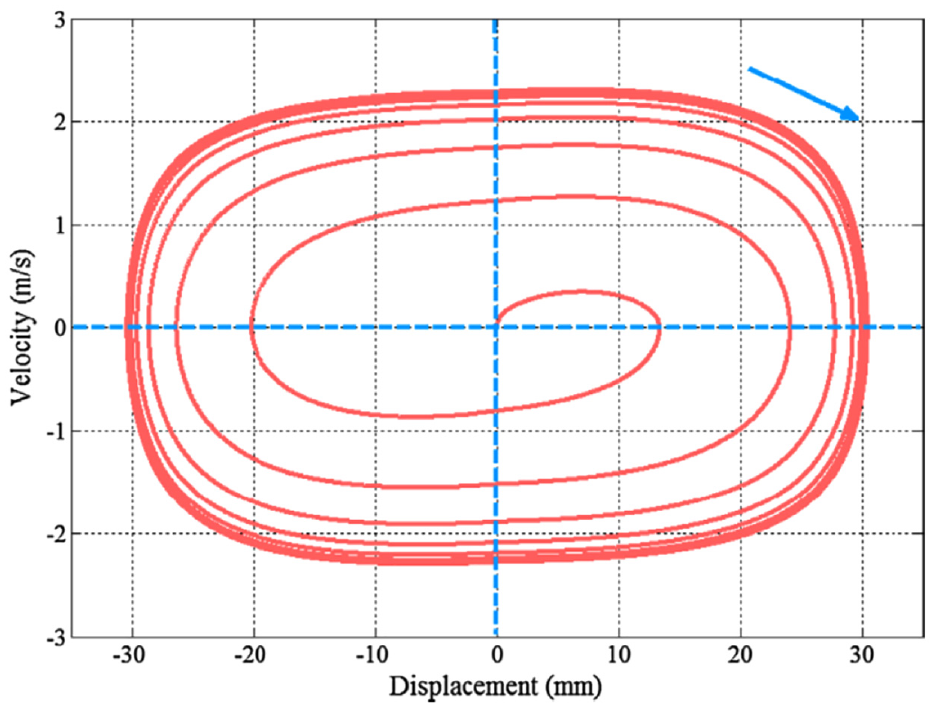
Velocity versus displacement with closed-loop control. 20
While most studies applied a constant motor force during the resonance starting process, Keller et al. 135 proposed a non-linear model predictive control (NMPC) strategy with multiple shooting discretisation to control the non-linear dynamic behaviour of FP-LEG during start-up, using the position-tracking method. Position-tracking behaviour between the NMPC and Linear-Time Varying Model Predictive Control (LTV-MPC) is shown in Figure 22. More accurate position-tracking and smoother start-up were realised with the NMPC strategy than with the LTV-MPC strategy, and less energy was required with the NMPC. With the LTV-MPC, the alternator accelerates and decelerates towards and after the piston’s dead centre positions to accurately track the desired position, thereby using more energy.
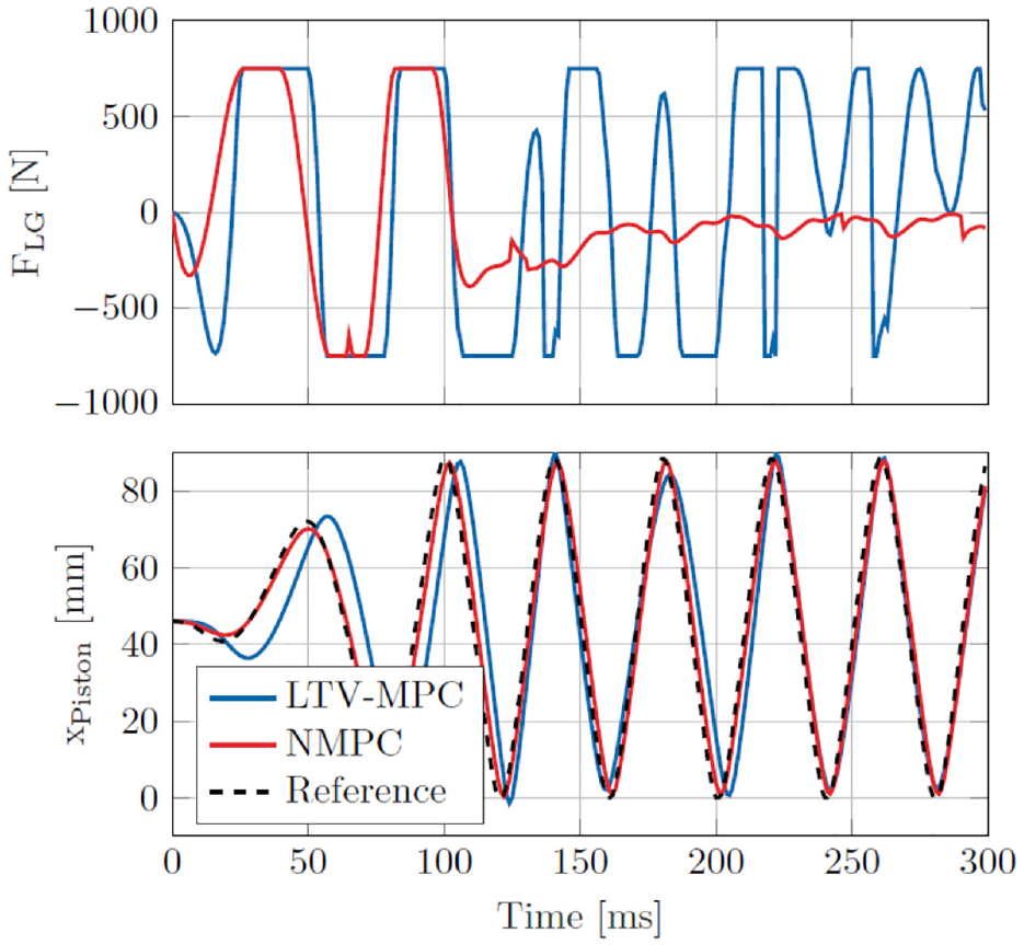
Linear alternator force and piston displacement with NMPC or LTV-MPC control strategy during LEG start-up process. 135
The alternator should switch from motoring mode to generator mode towards the end of the starting process. Considering the close-coupled layout of the FP-LEG, variation in motoring force will directly influence the system’s operation. Therefore, it is vital to realise a smooth transition from start-up to ignition stage by applying proper alternator switch mode. Feng et al. 139 investigated the influence of various switching strategies on the FP-LEG starting process. Piston motion changed more smoothly when the alternator gradually switched from motoring to generator mode. The output electromagnetic force decreased gradually from motoring to zero and then to a resistance force, Figure 23. The influence of various switch positions was investigated. The results indicated that switch at the TDC position led to the quickest switch without influencing the operating parameters at a steady state, Figure 24.
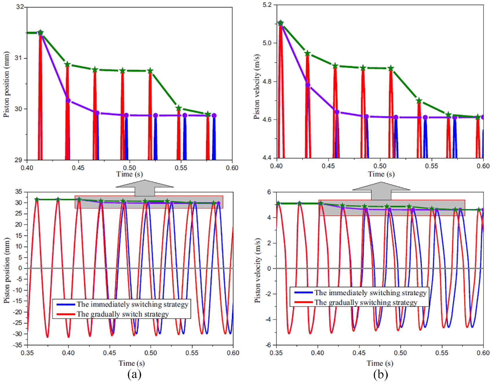
Simulation results with different switching strategies: (a) Piston position profile of the FPLG and (b) Piston velocity profile of the FPLG 139 .
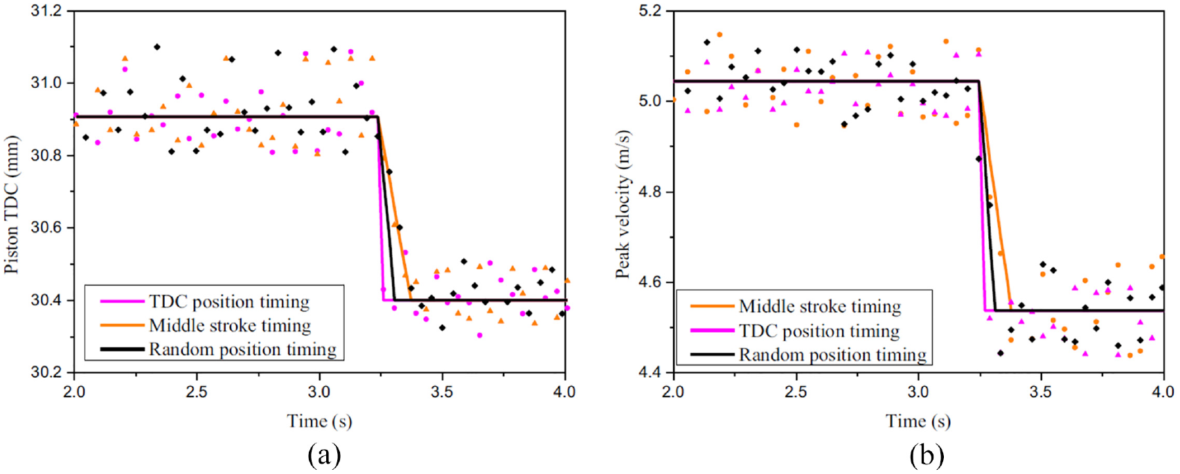
Piston TDC position and peak velocity with different switching positions during the intermediate process: (a) Piston TDC of the FPLG and (b) Piston peak velocity of the FPLG. 139
Yuan et al. 131 experimentally investigated the influence of starting force, connecting rod length and mover mass on the resonance starting method. The effects of heat transfer, friction, and leakage on the resonance starting were examined through simulation modelling. The piston dynamics and in-cylinder pressure increased with the starting force. Higher CR and peak pressure were achieved with the increasing connecting rod length; however, the duration to reach the stable state was longer, and piston velocity was reduced. As the mover mass decreased, piston velocity increased while the displacement amplitude decreased. The peak pressure firstly increased and then dropped. Therefore, an optimum mover mass existed for pressure build-up during the starting process. This was attributed to the trade-off between less gas leakage and higher friction resulting from lighter mover mass. Simulation results suggest that heat transfer influences the peak pressure build-up during the starting phase. Larger friction resulted in lower piston velocity, lower CR, and a more extended starting cycle. The influence of piston ring closed clearance indicated that smaller piston ring closed clearance led to lower energy loss and higher peak pressure. At the same time, the displacement amplitude increased because more alternator work was required to achieve equilibrium.
Stable operation control
Without the mechanical constraints from the crankshaft and flywheel mechanism, the piston motion of FP-LEG is dependent on the instantaneous sum of the forces acting on the piston mover, which are non-linearly coupled with each other. Any disturbance of a present cycle will directly affect the subsequent cycle and could damage the engine, or the engine would stall without adequate control of the disturbance. Cycle-to-cycle variations of the in-cylinder process make stable operation more challenging to achieve. Many investigations have been conducted on utilising effective and efficient control strategies to enable stable engine operation. These studies mainly cover parametric studies on control variables, various control logics/loops, and the application of the linearised dynamic model in controller design and development, which will be discussed in this section.
Control variables and various control methods
Most studies in the literature selected either CR or TDC position as the most critical control objective; however, different parameters have been adopted as the control variable. Among the control variables, fuel mass flow129,130,140 and the linear alternator force13,141,142 were the most common choice considering their apparent influence on the control targets.
Mikalsen and Roskilly 143 used TDC, BDC, and speed as the control targets, while fuel mass flow, fuel injection timing, and bounce chamber trapped air were selected as the control variables and load force was considered a disturbance. The stroke and speed increased with fuel mass flow per cycle. As injection timing was advanced, the stroke reduced, while marginal variation in speed was observed. The influence of load on piston dynamics indicated that piston stroke and speed decreased with increased load. The system gains of the control variables also changed non-linearly over the entire load range, suggesting a non-linear controller would be necessary to achieve satisfactory performance.
To achieve accurate and swift control, several control logics have been investigated and correlated. In addition, several innovative features have been proposed to make the control more efficient in energy consumption.
Mikalsen and Roskilly 130 compared the engine response to rapid load changes when various controllers were applied. Proportional-integral derivative (PID), pseudo-derivative feedback (PDF) and PDF combined with disturbance feedforward (PDF + FF) controller were applied; the diagrams of the control systems are shown in Figure 25. The PDF + FF controller provided better responses than PID and PDF in CR and in-cylinder pressure control.
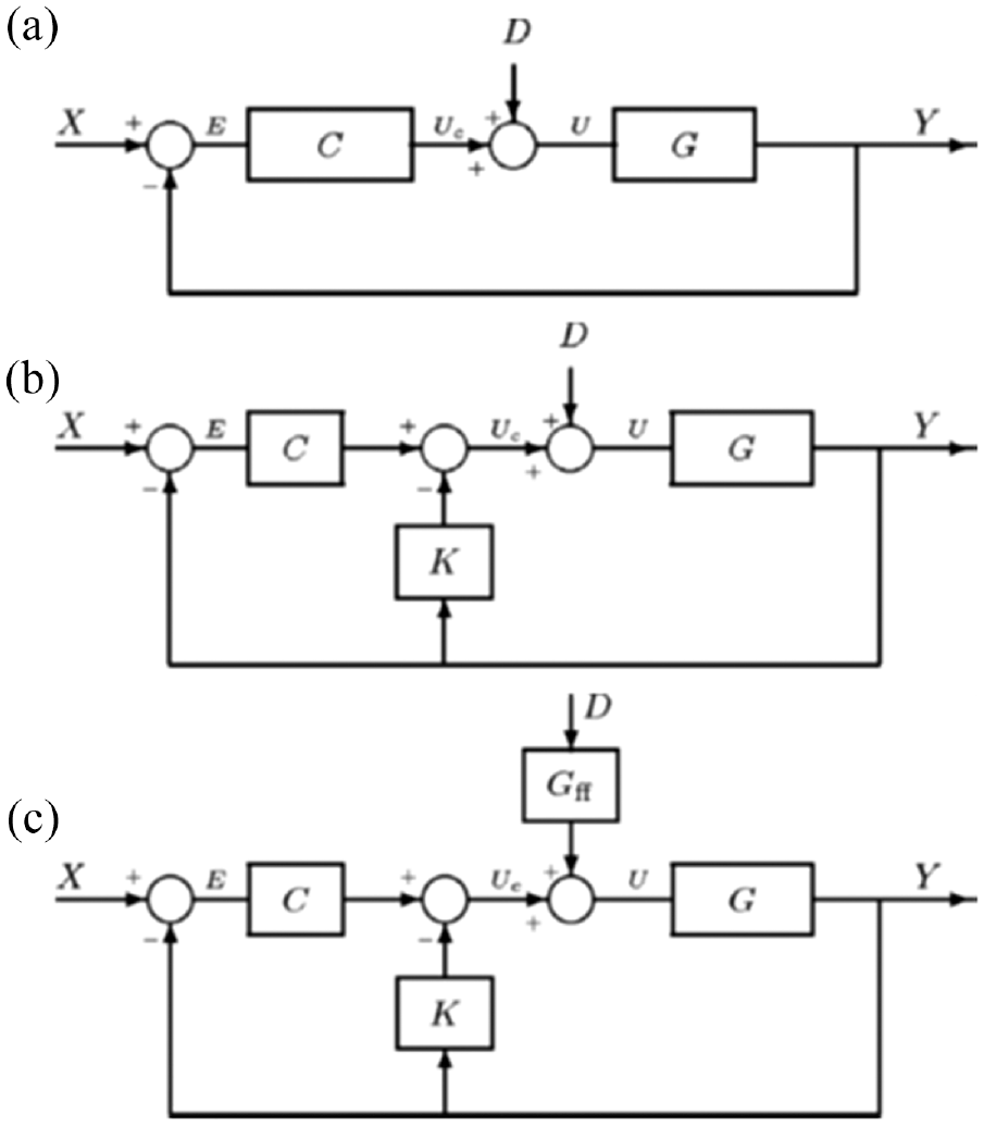
Diagrams of various control system: (a) PID, (b) PDF, and (c) PDF + FF. 130
A Cascade control strategy proposed in Jia et al. 129 indicates that adding a second loop, using piston velocity of current stroke as the control feedback, to the first loop, which used the TDC position of the previous stroke as the control feedback, as shown in Figure 26, improved the control delay, peak error and settling time compared with single-loop control.
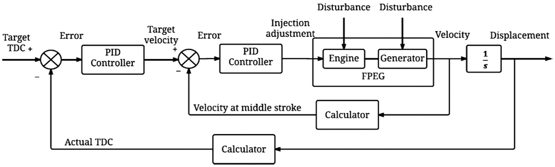
Block diagram with cascade control. 129
Li et al. 144 developed a linear model to mimic a predefined reference piston trajectory. This was achieved using the closed-loop control strategy for motoring and generating modes and improving the engine start-up and stable operation while decreasing the cycle-to-cycle variations. Graef et al. 99 proposed a piston motion control strategy, where the piston position determines the valve, fuel injection and ignition timing and Ngwaka et al. 50 used a similar approach of predefined piston positioning to achieve piston control and optimal valve and ignition timing for two and four strokes hydrogen-fuelled FP-LEG testing. A sinusoidal profile was used in the piston motion pre-set trajectory. 145 By comparing the variation between the actual piston position and the pre-set target position, the target linear alternator electromagnetic force needed to achieve the target position was computed and implemented to achieve real-time piston position modulation. The pre-set piston profile was successfully tracked, and the prototype achieved stable operation with the control strategy. However, due to the frequent change in the excitation of the alternator and the variation of the alternator’s energy flow direction, the system’s power generation efficiency degraded. Wu et al. 146 used the trajectory tracking control method to minimise cyclic fluctuation and maintain the system’s stable operation and operational targets. Vu and Lim, 136 investigated the predictive-fuzzy logic (PFL) control, and the results indicated that it is a more effective control strategy. It improves the engine performance compared to the PID in settling time, target TDC error, and cycle-to-cycle variation. Results show that the PFL control reduces settling time by 30% compared to the PID control and has a 0.24 mm improved TDC position error than the PID controller and the coefficient of variation values are 1.0% and 1.9% for the PFL and PID controller.
A target position feedback controller for single-piston FP-LEG was presented in Kosaka et al. 126 and Goto et al. 141 The load coefficient, kr, proportional to the piston velocity, served as the main generation gain; additionally, both position and velocity feedback loops were utilised for piston trajectory control, as indicated in Figure 27. The control strategy could maintain oscillation without combustion, ensuring robust operation under unexpected abnormal combustion conditions. Satisfactory control of piston trajectory was realised with a well-controlled alternator current and minimised power consumption by following the pre-set sinusoidal position profile. Test results indicated that the controller effectively stabilised the system when abnormal combustion, such as pre-ignition, occurred. 80 However, the fluctuations in pre-set position cases increase for severe retarded ignition positions or fuel injections, resulting in unstable combustion. 126 The same trend is observed with other operating parameters such as frequency and desired power. This indicates that one pre-set position profile will favour stable operation within limited operating conditions. A specific pre-set profile matrix is required to realise a stable operation for the various operating conditions. Therefore, the resonant pendulum-type control method is proposed, and its block diagram is shown in Figure 28.13,126 The resonant pendulum-type control strategy was utilised to mitigate linear generators’ low efficiency in low-speed regions. As indicated in Figure 29, the LG functioned only around the mid-stroke, where the piston speed was highest, allowing the piston to move freely during the remainder of the stroke. The resonant pendulum-type control method is based on speed control without a fixed reference profile of the piston motion. This control method supports the flexible piston stroke and frequency phase due to no specific frequency input and the piston motion profile. This control method could control the error of TDC and BDC positions within 1 mm in both motoring and firing modes. 13 In addition, this study found that the motoring energy consumption and power generation could be optimised by manipulating BDC position and gas bounce chamber pressure, respectively. The test result demonstrated that the resonant pendulum-type control method is robust to changes in operating parameters compared with the targeted position feedback control method. 126
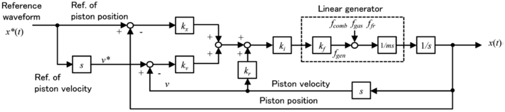
Block diagram of the target position feedback control logic. 80
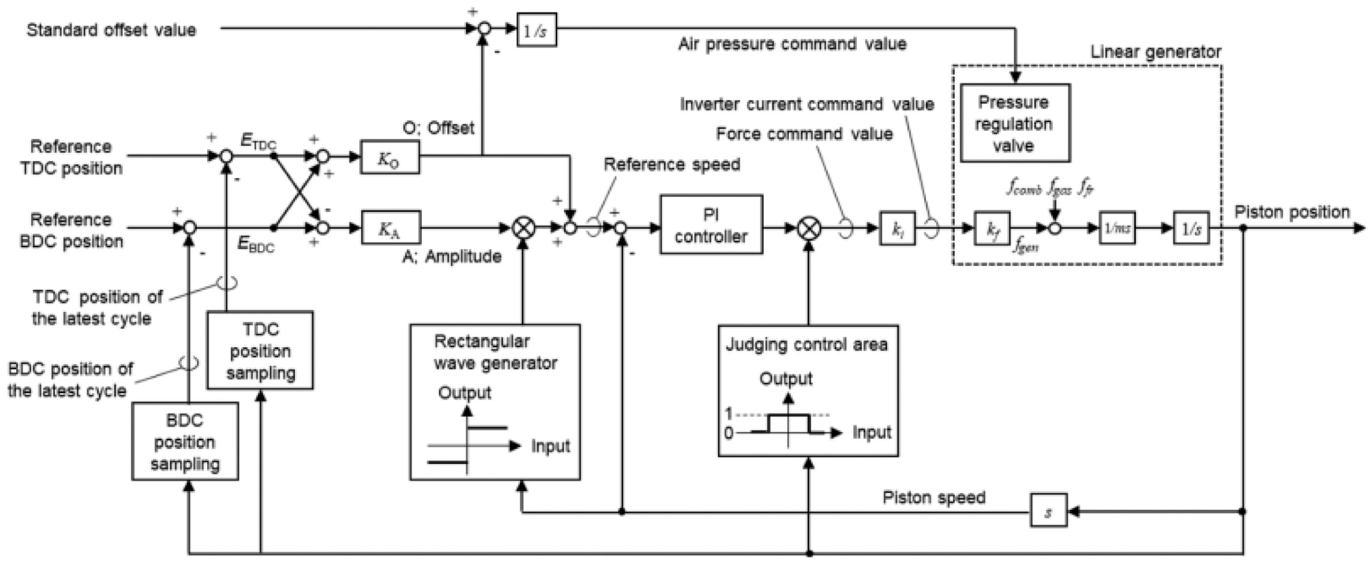
Control logic block diagram of resonant pendulum type control method. 126
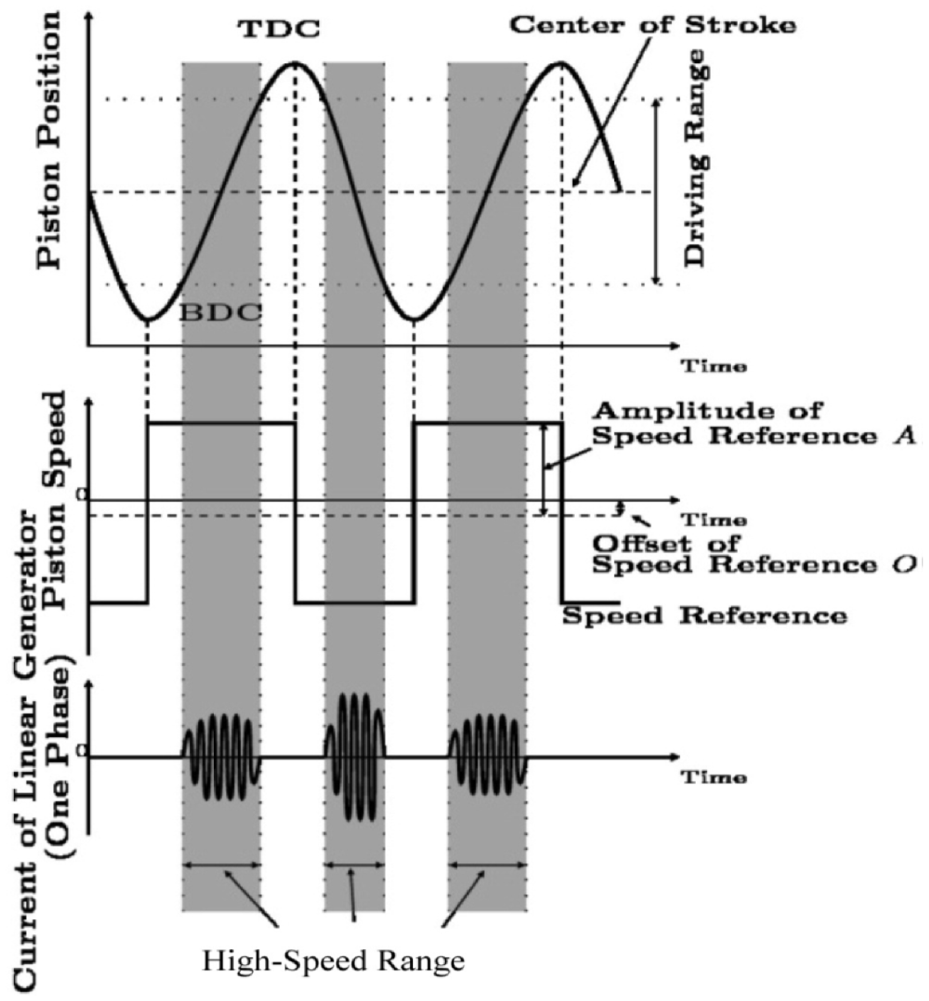
Diagram of the resonant-pendulum-type control method. 13
In order to manipulate the CR of FP-LEG for improved performance, Lin et al. 142 proposed a feedforward and feedback composite control strategy. The in-cylinder pressure was considered the disturbance, and alternator force was considered the control variable. The feedback control was combined to counteract the fluctuation of in-cylinder pressure and minimise the steady-state error. The linear-quadratic optimal control theory derived the optimal feedback control constants. Figure 30 shows the diagram of the proposed composite controller. Where Fm(k) is the electromagnetic resistance force in stroke k + 1. P3 is the peak pressure, reference position value x-ref, and x is the position (state variable).
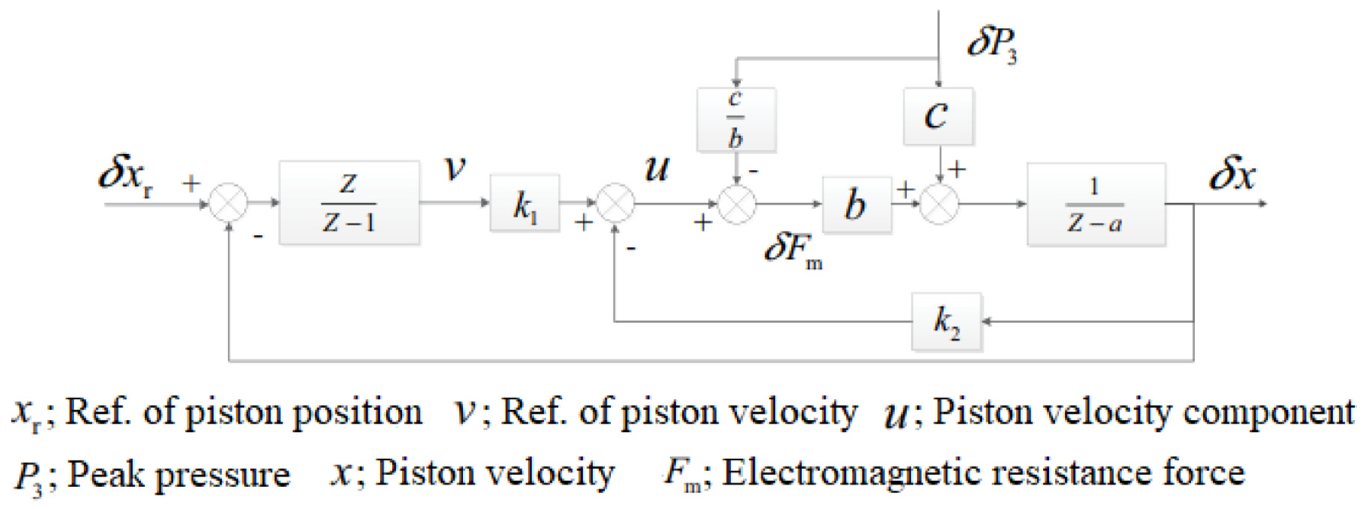
The feedforward and feedback composite controller of FPLG. 142
Gong et al. 147 proposed a dual-loop control model for a four-stroke four-cylinder SI FP-LEG. The control system consisted of two controllers, as demonstrated in Figure 31. An outer-loop model predictive control controller was derived by linearising the nonlinear dynamic model of the FP-LEG and was used to generate the set-points for both air flow and electric load. Then, the nonlinear air-path controller adjusted the throttle angle to reach the airflow set-point. Finally, the control variable, fuel mass flow, was calculated based on the airflow requiring a stoichiometric air-fuel ratio. Simulation results suggested a reliable performance of the control model.
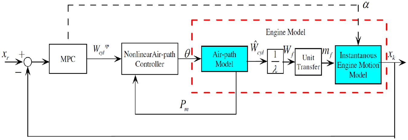
Structure diagram of the dual-loop control system. 147
Hardware in the Loop (HIL) techniques, which involves using an accurate real-time emulation to replace a piece of hardware, has achieved broad acceptance as a tool for rapid testing and development of data acquisition systems and control strategies for systems and components in several industrial applications. Including the automotive and energy sectors, where full-scale prototyping’s cost, safety, and complexity could be vital. 148 A fast-response FP-LEG model, which could be applied in the HIL development of the FP-LEG control system was developed by Jia et al. 149 The dynamic equation of FP-LEG was reduced to a forced vibration system with viscous damping, and the nonlinear part (in-cylinder pressure) in the dynamic model was linearised 150 through first-order Taylor expansion. 149 Some assumptions made during linearisation include adiabatic compression/expansion, constant volume combustion, ideal gas, and no friction. As a result, the piston position can be predicted much more quickly than the nonlinear dynamic model, which is beneficial for real-time HIL application.
Summary
The FP-LEG is especially susceptible to the load. The most prevalent control concept is that the linear generator controls the piston trajectory. A predefined reference trajectory is considered among the most suitable strategies because the load and combustion parameters will be the input variables and could be optimised to achieve the desired referenced piston trajectory and efficiency. However, the resonance starting method is effective, and the nonlinear model predictive control (NMPC) demonstrated the potential to enable a smooth, accurate and energy-efficient start-up of an FP-LEG. An optimised position-tracking mode is recommended in motor force reversing control. A comparison between the open and closed-loop control strategies demonstrated that the closed-loop strategy effectively counteracts the back electromagnetic voltage resulting from the mover’s motion. While CR or dead centre position was always the control objective, energy input or the force at LG was the most popular control variables. The feedforward and feedback composite control strategies with various features have been widely applied and proven effective. It is expected that future FP-LEG control investigations will focus on advanced piston trajectories models for further performance optimisation.
Conclusions
Efforts have been made to investigate the FP-LEG to turn its attractive merits from theory into practical application. In this paper, the performance indicators of the FP-LEG were summarised based on test data published in the open literature to demonstrate what has been achieved so far. The rest of this paper focused on the up-to-date progress in realising reliable start-up, stable running operation and optimised performance, which is the foundation for further development.
Despite much work on FP-LEG research and development, system performance data from test studies have rarely been reported. However, commercial operational FP-LEG is available, indicating that most of the technical challenges to achieving stable operation are solved. Based on the data available, it is possible to achieve impressive efficiency when applying non-conventional combustion modes such as HCCI. Not many studies have been done on Joule Cycle FP-LEG; however, the published performance of a few studies shows encouraging results. More test data from stable operations will be of great value to verify the efficiency merits of FP-LEG. In addition, as some of the studies are still in the proof-of-concept stage, which mainly targets performance, it is still too early to have a valid comparison of weight/power or package/power ratio towards its conventional crank counterpart, which may already include additional design features to deal with durability. While either CR or dead centre positions are consistently selected as the control objective in FP-LEG control, energy input and the LG force are the most popular control variables because of their apparent influences on the control targets. Interesting ideas, such as operating the LG only in its high-efficiency region, have been proposed to improve system efficiency.
The resonance starting method is common in the IC FP-LEG and proved more appropriate than the one-stroke generator starting method. For the Joule Cycle FP-LEG, an external compressed gas is used for starting; however, it is possible to use the LG in motor mode to start the Joule Cycle FP-LEG. The gas exchange processes in IC FP-LEG and system control are the fundamental challenges in achieving high efficiency and reliable FP-LEG operation. However, with external combustion in Joule Cycle FP-LEG and adopting HCCI combustion in IC FP-LEG using alternative fuel with higher combustion speed to speed up combustion, such as hydrogen, to enable the combustion process and release more heat around TDC, improved efficiency is possible. Therefore, more focus should be devoted to properly controlling the FP-LEG system.
Footnotes
Declaration of conflicting interests
The author(s) declared no potential conflicts of interest with respect to the research, authorship, and/or publication of this article.
Funding
The author(s) disclosed receipt of the following financial support for the research, authorship, and/or publication of this article: The authors are grateful for the financial support from EPSRC (Engineering and Physical Sciences Research Council, United Kingdom) through the project ‘Powering Carbon-free Autonomous Shipping: Ammonia/Hydrogen dual-fuelled Linear Engine-Generator (EP/S00193X/1)’ and the Major Program of Zhejiang Provincial Natural Science Foundation of China (Grant No. LD21E070002).