
Abstract
This paper presents a detailed quasi-dimensional model that can assist in the design process as it allows predicting the performance and emissions of compression ignition (CI) engines functioning with different fuels, such as kerosene and Diesel. The proposed model includes a new dedicated fuel injection mass flow rate sub-model that is coupled to the multi-zone spray packet concept for spray development. Moreover, fuel spray development and its interaction with in-cylinder swirl is considered and allows studying the influence of combustion chamber design, fuel injection strategy, as well as fuel properties. The model is validated against single and double injection strategies using kerosene and diesel fuels and is shown to be capable of predicting engine performance with a good accuracy. The results obtained from the parametric studies have shown proper trend with respect to the effect of the bowl-to-bore diameter ratio, EGR rate and temperature or fuel properties. This latter predicts that fuels with higher lower heating values (LHVs) can decrease NO and soot emissions by using retarded injection timing, while the boiling temperature has a small effect on the evaporation and mixture formation process. Finally, a fuel with a high enthalpy of vaporization can achieve lower soot emissions by increasing the swirl ratio or increasing the injection timing although doing so is detrimental to the power output.
Keywords
Highlights
A zonal thermodynamic model with a real injector-based injection model is proposed
Fuel thermophysical properties are stored in kinetic mechanism-based lookup tables
The model is able to assist in the performance-emissions tradeoff decision
Cooled EGR help reducing both NO and soot emissions
High LHV and low boiling temperature of the fuel leads to better performance
Introduction
Diesel engines are widely used in the transportation sector and, to some extent, in power generation. 1 Engine manufacturers and researchers focus on improving and optimizing the engine design and on testing new fuels such as biodiesel,2,3 hydrogen-enriched fuels,4,5 or kerosene.6,7 Pairing and testing the available technologies such as the exhaust gas recirculation (EGR) or biofuels are among the possibilities to mitigate the pollutant emissions while ensuring good performance. 8 Modeling the different phenomena taking place within diesel engines, such as with a quasi-modeling approach, can contribute to the design and improvement processes. The quasi-dimensional modeling of engines offers different levels of complexity to the physics at play within the engine, such as how to simulate the combustion heat release rate HRR. One simple approach to the HRR involves the implementation of a Wiebe9,10 or dual Wiebe function, 11 while another more complex method includes a spray model describing the fuel injection and evaporation process allowing determining the rate of fuel evaporation.12,13 More complex phenomenological models have been proposed in order to link the injection process to the burning rate. This approach has been used to study the combustion noise and NO emissions under a split injection strategy in a Diesel engine. 14 In that case, the combustion model was divided into an ignition delay period, a premixed combustion and a mixing-controlled combustion. In other cases, the injection rate is also considered, by using a model derived from the Bernoulli equation15,16 or by tuning its value to reproduce the experimental HRR. 17
One of the most advanced phenomenological models to describe fuel spray combustion was proposed by Hiroyasu et al.,18–20 and consists in discretizing the spray into small discrete packets in the form of numerous thermodynamic zones. This approach allows a more detailed modeling of local processes such as fuel atomization, evaporation, mixing, ignition, combustion and pollutant formation in each elementary packet. The results from this approach show a good prediction of the spray development, of the HRR, and of the cylinder pressure over a wide range of operating conditions.16,21 One of the advantages of the approach is the low computational cost related to the calculation of the combustion species concentrations, which are taken at equilibrium,22,23 instead of resorting to a kinetic mechanism.24,25 An in-between alternative was proposed in the work of Men et al. 26 by using a two-equation kinetic.
Over the years, and in parallel to this modeling development, there has been a great interest in the study of the impact of fuel properties on Diesel engine performance and emissions (see, e.g. Karonis et al. 27 and Atmanli 28 ). Some researchers have used a statistical approach to optimize fuel blend properties and engine performance 29 or to quantify the significance of certain properties. 30 The main objective in these endeavors has been to identify the fuel properties having the greatest influence on engine design or to help identify promising alternative fuels or blends. For example, Lee et al. 31 experimentally compared a base and a light diesel fuel to examine the effect of fuel properties on the potential to decrease the pollutant emissions of a Diesel engine. They observed that a lower boiling point diesel fuel favors fuel atomization and evaporation. Eismark et al. 32 evaluated, at three engine loads, the effect of fuel properties in a heavy-duty engine, using different fuel compositions. They reported that at low load, low boiling fuel (expressed as T90, the temperature at which 90% of the mass is evaporated on a distillation curve) and high H/C promoted fuel evaporation, and thus produced lower soot emissions. On the other hand, at medium and high loads, high H/C and increasing O/C were more important properties when it came to decreasing soot. Another approach was adopted by Mehta et al., 33 who created four blends of Diesel/butanol/biodiesel in different proportions, but having similar properties as a conventional diesel fuel including viscosity, LHV and cetane number. They reported a decrease in NO for all the blends when compared to diesel fuel. While these approaches show specific trends, they make it hard to identify the cause and effect associated with a fuel particular property due to the fact that when the fuel composition is modified, it also simultaneously changes other properties as well as the combustion chemistry. To circumvent part of the problem encountered with the experimental approach of studying fuel properties, effective phenomenological models could prove helpful and be complimentary tools to CFD modeling and experimental studies. They could also help identify the most influential fuel properties for use in identifying potential blendstocks, such as the ones of Fioroni et al. 34
As mentioned above, EGR is a popular technique to reduce NO emissions by lowering the oxygen concentration and the flame temperature of the gaseous mixture while increasing the specific heat of the intake charge. 35 Recent literature shows that combining biofuels and EGR is of great interest to further reduce emissions. Pathak et al. 36 notably reported NOx and smoke reductions of 21% and 18%, respectively, using dual fuel (Diesel with 20% of natural gas) combined with 5% of EGR. The effect of EGR rates and its temperature was studied by Patil and Thirumalini 37 with a twin cylinder engine fed with Diesel and a blend of Diesel-Karanja B20. The results show that 15% of uncooled EGR combined to B20 reduces NO emissions by 67% at high load and that cooling the EGR has no significant effect on the NO level. However, it has been reported, based on simulation results that EGR cooling has a positive effect on thermal efficiency 38 but that the risk of water condensation limits the cooling and the use of EGR, particularly at cold start. To tackle such an issue, Luján et al. 39 developed a simple mathematical model that predicts the condensation conditions inside the EGR circuits. Finally, the use of uncooled low-pressure EGR is useful even during engine cold start operation to decrease NO, while after-treatment systems are disabled, and to accelerate the engine warm-up period. 40 However, uncooled high-pressure EGR seems to be preferable under cold conditions to avoid water condensation and carbon emissions. 41
This short literature survey thus highlights that efforts undertaken in the field of quasi-dimensional modeling include the development of fuel spray penetration and mixture formation sub-models as well as the implementation of different approaches to model the combustion process (from the imposed HRR to the recent use of kinetic schemes), so-enabling predicting engine performance and/or studying the impact of EGR. However, it is noted that parametric studies conducted with such models are often limited to the impact of injection timing or of EGR rates but rarely cover the influence of fuel properties or of the piston design and its impact on performance and emissions. Furthermore, the injection process is often represented by a constant mass flow rate without considering the injector dynamic. Considering the importance given to biofuel blends, it seems that modeling effort should enable studying fuel blends and their impact on engine performance. From these observations, the main objective of the present work is to propose a Diesel engine model useful for design, considering novel technologies and fuels over a wide range of conditions. To meet that broad objective, a quasi-dimensional model which includes a new injection sub-model as well as the possibility of investigating complex fuel blends is proposed. This latter capability is possible by conducting equilibrium calculations with a chemical kinetic to generate lookup tables of gaseous properties and species concentrations needed to predict soot and NO emissions as well as engine performance.
The paper is organized as follows: thereafter a presentation of the model, a validation is carried out against experimental results using Diesel and kerosene. Over the past years, kerosene has attracted a lot of interest and has been extensively covered in experimental6,42,43 and CFD 44 studies. Indeed, kerosene fuel is foreseen as a good candidate to the single fuel concept 45 and an alternative to conventional Diesel in blendstock fuels. 46 Hence, this paper aims at also bridging the gap between experimental and CFD works using a kerosene surrogate. The capability of the model to be used as a design tool is then presented using a parametric approach.
Model formulation
This section presents the conceptual description of each sub-model involved in the simulation code. The Matlab environment is used to implement the computer program.
Single-zone thermodynamics
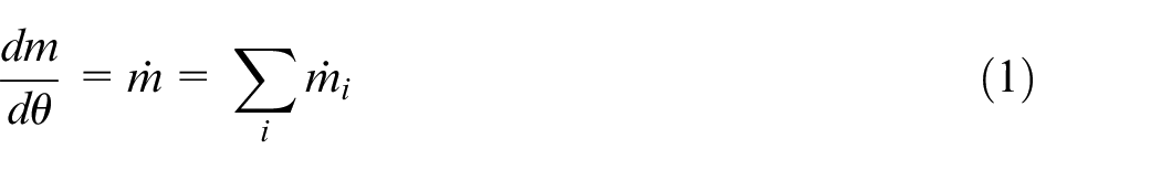
In this paper, a 0D approach is assumed and a single zone is used similarly to Jung and Assanis 16 to represent the cylinder volume and its boundaries. The control domain is viewed as an open system, which can exchange mass and energy with the outer region. Hence, the conservation of mass in the zone can be expressed as:
The gas exchange process at the intake and exhaust valves and the fuel mass flow rate injected in the cylinder (
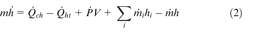
The conservation of the energy applied to an open system can be expressed as in equation (2):
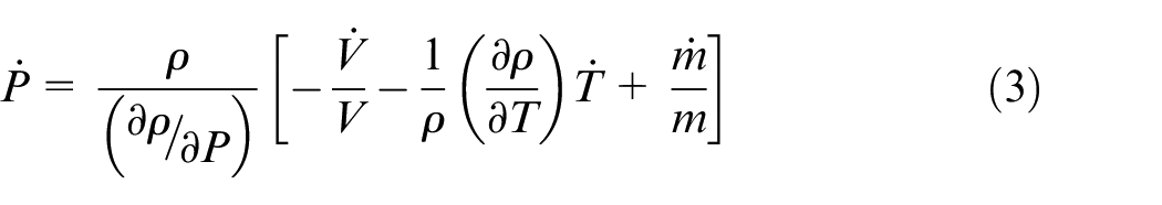
The system is assumed to behave as an ideal gas being in thermal equilibrium and the gas enthalpy is considered only as a function of the temperature
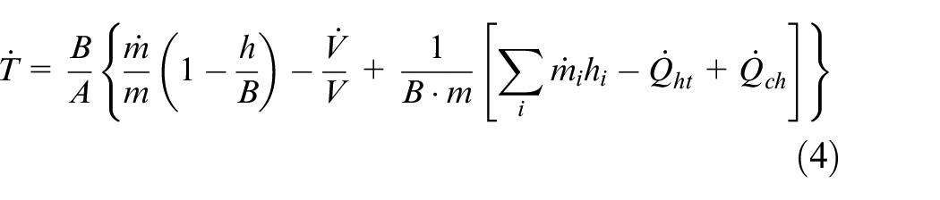
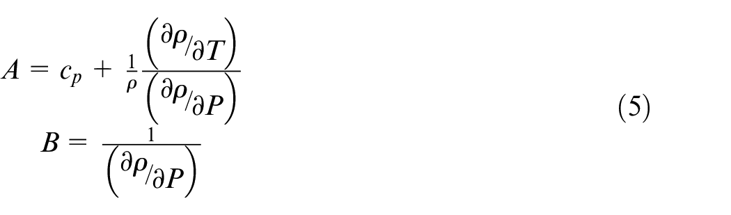
After substituting the rate of change of pressure and the temporal derivative of the enthalpy in equation (2), an expression for the rate of change of the cylinder temperature is found (equation (4)):
where:
The equations above, as well as the ones described in sections “Wall heat transfer” and “Fuel spray and heat release”, are solved at each time step using a simple first-order Euler method.
Chemistry of combustion and thermophysical properties
The solver Cantera 47 is used to calculate the combustion products at equilibrium as well as the thermophysical properties of both an air-fuel mixture and a pure gaseous fuel. The thermophysical properties of fuel vapor are tabulated as a function of the temperature whose values range from 275 to 3500 K. Similarly, the properties of the air-fuel mixture and its composition at equilibrium for 11 species (CO2, H2O, N2, O2, CO, H2, H, O, OH, NO, and N) are calculated over a range of equivalence ratios, pressures, and temperatures representative of the conditions encountered in a Diesel engine. Gaseous properties are thus estimated through interpolations of lookup tables generated with Cantera and detailed chemical kinetics. As different fuels are used in the proposed engine model, the kinetics of 1-Undecene C11H22 (serving as a kerosene Jet-A2 surrogate) made of 71 species involved in 538 reactions, including NOx chemistry from Saggese et al., 48 as well as that for n-dodecane C12H26 (serving as a Diesel surrogate), 49 are used to this end. The use of lookup tables generated from detailed chemical mechanisms prior to the calculations is of interest if various fuels are to be tested and when polynomials are not readily available in the literature in order to approximate the mixture’s thermophysical properties. Furthermore, the results from the equilibrium calculations are used as input to predict nitric oxide (NO) and soot emissions using the extended Zeldovich mechanism 50 and the semi-empirical model proposed by Hiroyasu et al., 19 respectively.
As exhaust gas recirculation (EGR) is commonly used to decrease NO emissions, its effect on the mixture properties is implemented using another set of lookup tables expressed as a function of EGR rates, on a mass basis, ranging from 5% to 20%, as defined by equation (6):
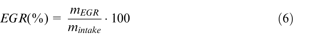
To avoid multiplying the number of EGR lookup tables, the equivalence ratio of the initial unburned mixture was chosen equal to 0.5, considering that Diesel engines always operate with lean mixtures and that the main EGR component is nitrogen. To predict pollution emissions, a sub-model was developed as a post-processing tool based on the lookup tables above. When simulations were run without EGR, the gas composition at equilibrium and the pollutants were computed using the algorithm of Olikara and Borman 22 as it provides the fastest computational speed. A comparison with the predicted emissions with the lookup tables and the algorithm of Olikara and Borman 22 showed differences of less than 1%.
Gas exchanges processes
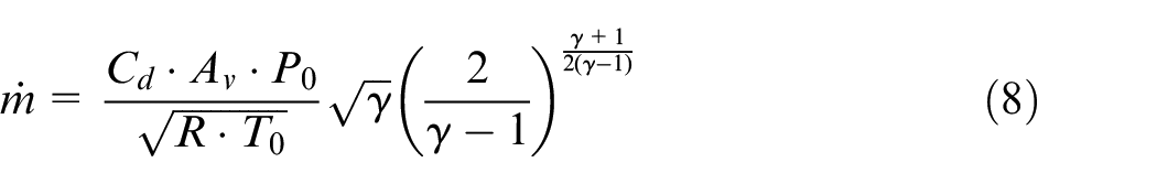
The instantaneous mass flow rate across the intake and exhaust valves is calculated using equation (7), resulting from a one-dimensional analysis of a compressible and isentropic flow through an orifice 1 :
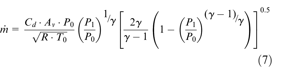
Equation (7) is used when the flow is not choked
The correlations for the valve radius from Heywood
1
and the opening valve area (
Wall heat transfer
The evaluation of heat losses by forced convection and radiation – the latter being considered during the combustion phase only – from the gas to the cylinder wall relies on equation (9), where the heat transfer coefficients are the ones proposed by Annand 52 :
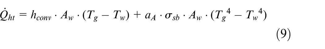
In this equation,
Fuel injection
Using single and multiple injection strategies translates into different injection profile characteristics that need to be modeled. For that purpose, a new injection model is proposed and is based on an analytical solution of the response of a first-order linear dynamic system to an impulsion.
53
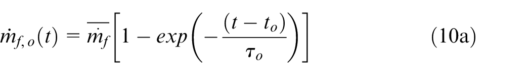
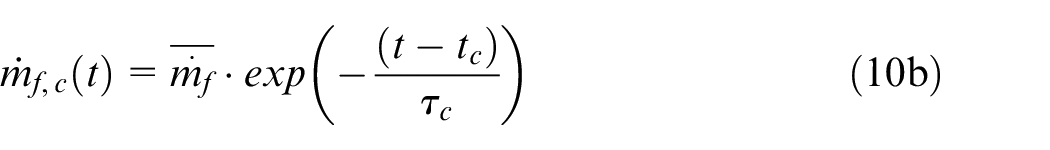
The injection sub-model has been validated with experimental mass-flow rate profiles obtained under a wide range of injection conditions with an emphasis on single and double short duration injection. Thus, for a short injection, which is characterized by a triangular profile because of the ballistic motion of the injector needle, it is proposed to model the rate of injection (RoI) using an exponential growth (equation (10a)), during injector opening, and an exponential decay (equation (10b)), during injector closing, that are fitted on the experimental RoI profile. Equation (10a) presents the RoI as a function of the mean steady-state mass flow rate (
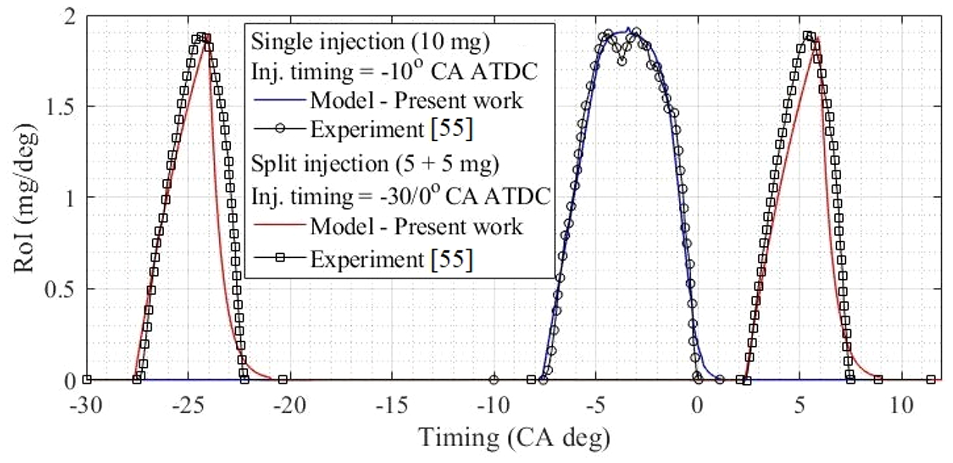
Comparison of the RoI profiles from the experiment 55 and the model. Double injection is modeled using two triangular injection profiles while a trapezoidal profile is used for the single injection.
Fuel spray and heat release
The injection instantaneous mass flow rate above is coupled to the rate of heat release through the fuel spray model. After initiation of the fuel injection in the cylinder, the spray penetrates through the air trapped in the combustion chamber. The physics of the spray and the ensuing heat release used the “packet model”, developed by Hiroyasu et al. 19 The physical concepts and assumptions underlying this model are presented in the next sections.
Spray development
Once the injection starts, the spray continuously forms and is discretized into small individual packets in the radial and longitudinal directions. The number of packets in the radial direction is kept constant, following a sensitivity analysis, and is equal to J = 10 divisions, as originally used by Hiroyasu et al. 19 As the spray enters the combustion chamber at each time step, a new column of 10 packets is added at the injector orifice. Thus, the number of packets in the longitudinal direction is dependent on the injection duration. Figure 2 shows the division of the spray in both directions noting that the coordinates (j, i) associated with each packet corner are visible in the inset.
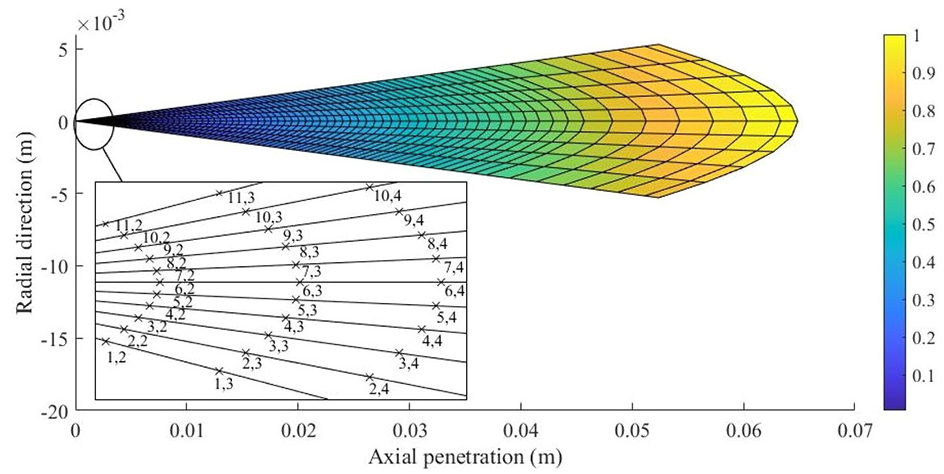
Description of the spray packet model (the scalar field denotes the non-dimensional penetration).
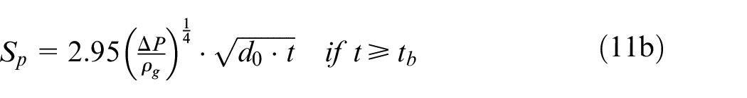
The injection velocity at the injector orifice (and the spray tail after the end of the injection) are calculated using the equation of momentum flux, 56 using the RoI of section “Fuel injection”. The spray tip penetration is calculated with the empirical correlations of Jung and Assanis 16 (equations (11a) and (11b)):
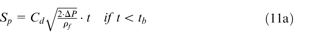
where
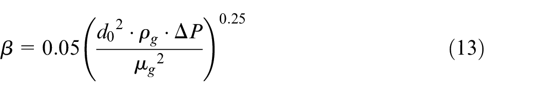
The overall fuel quantity delivered by the injector is evenly shared between the injector orifices. The derivation of equations (11a) and (11b) with respect to time gives the evolution of the spray tip velocity. A linear velocity profile along the spray axis from the nozzle orifice to the spray tip is assumed. The packets at the edges of the spray experience drag due to their relative velocity difference with the surrounding air. At a given axial position in the spray, the packet located on the axis travels faster than its neighboring packet and a Gaussian velocity profile is assumed. 19 The geometric description of the spray is completed with a correlation for the spray angle (equation (13)) 57 :
Spray-charge motion interaction
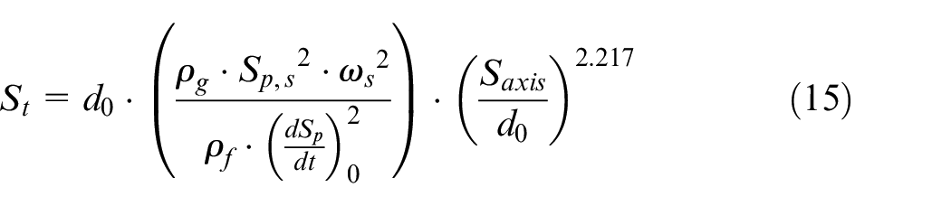
Following the determination of the mass captured within the cylinder from the above section, the large-scale rotating fluid motion created by the intake port is also considered in the cylinder as it impacts the fuel spray penetration and promotes the air-fuel mixing rate. This phenomenon is taken into account by using a correction factor applied to the fuel spray penetration, as shown in equation (14) 19 :
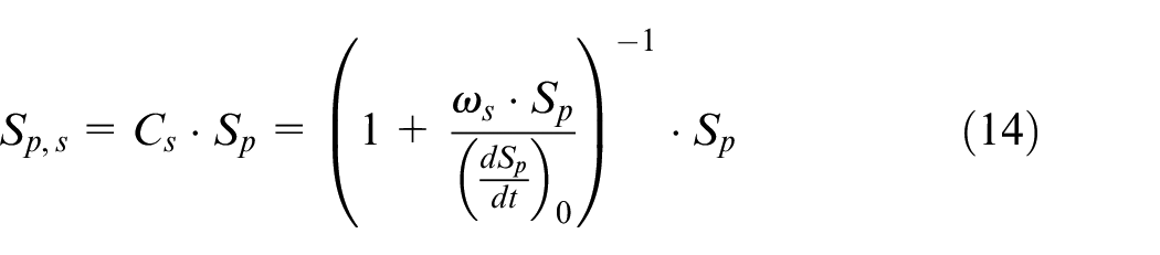
where
The value of the swirl ratio is not constant throughout the engine cycle, and is estimated from the conservation of angular momentum of the cylinder content following the methodology described in Dobos and Kirkpatrick 24
Air entrainment
Following a liquid core breakup, the fuel mixing with air is controlled by the conservation of momentum applied to each packet. 19 The rate of air entrainment is expressed by equation (16) 16 :
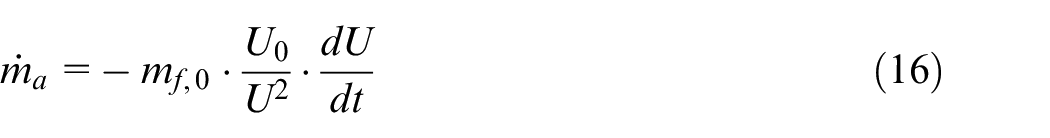
The packet acceleration,
Fuel atomization and evaporation
After breakup, two hypotheses are used in the model. First, the atomization of the fuel droplets contained in each packet is assumed to be instantaneous. Second, the droplets contained within a packet all have the same diameter, thus neglecting size distribution. After breakup, the diameter corresponds to the Sauter Mean Diameter (SMD) given by equation (17) 59 :

where
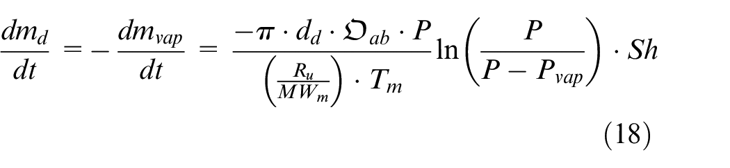
In equation (18), the Sherwood number
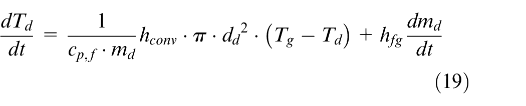
where the formulation of the convective heat transfer coefficient
Liquid fuel properties
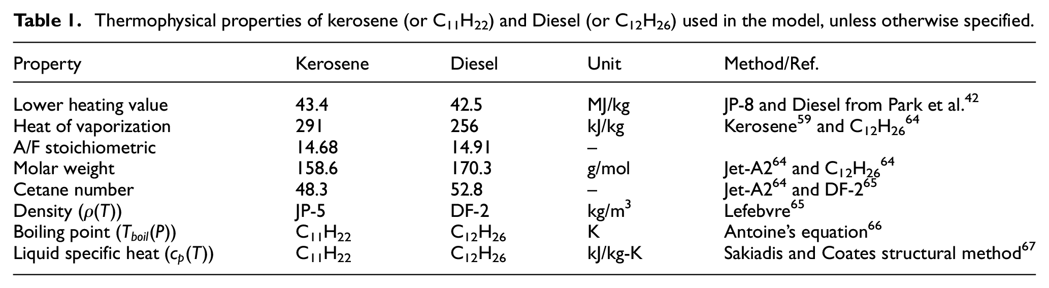
As one of the objectives of this work is to propose a model that allows pursuing engine design adaptation as a function of the fuel, thermophysical parameters of the liquid fuels are summarized in Table 1, where the reference state is taken at 1 atm and 298 K. When fuel properties could not be found, 1-Undecene (C11H22) and n-dodecane (C12H26) properties were used for kerosene and diesel fuel respectively. Besides, when considering a multi-species fuel in the model, its properties are estimated applying a mixing rule based on the composition of the fuel.
Thermophysical properties of kerosene (or C11H22) and Diesel (or C12H26) used in the model, unless otherwise specified.
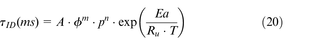
Ignition delay and combustion
The ignition delay is a function of the fuel and the mixture temperature, pressure and equivalence ratio. Herein, the ignition delay is calculated using equation (20),
68
where
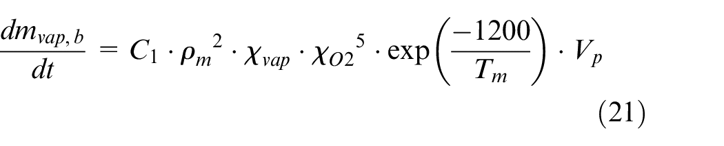
Following the ignition delay period, the mass of fuel evaporated and mixed with air during this period burns rapidly resulting in a fast-premixed combustion phase that follows an Arrhenius law (equation (21)) to limit the rate of fuel conversion in premixed flame as proposed in Nishida and Hiroyasu.
69
Following the initial premixed oxidation stage, the combustion rate is governed by the rate at which the unburned fuel remaining in the packet forms fresh mixture with the entrained air. The fuel burning rate in a packet is limited by the most stringent of the following three criteria
21
: (1) for lean or stoichiometric mixture
where,
Model validation
The model is validated against experimental data available in the literature. Two different sets of results42,55 have been selected allowing validation against single and double injection strategies, and with two different fuels. The specifications of the engines used in Park et al.42,55 are listed in Table 2.
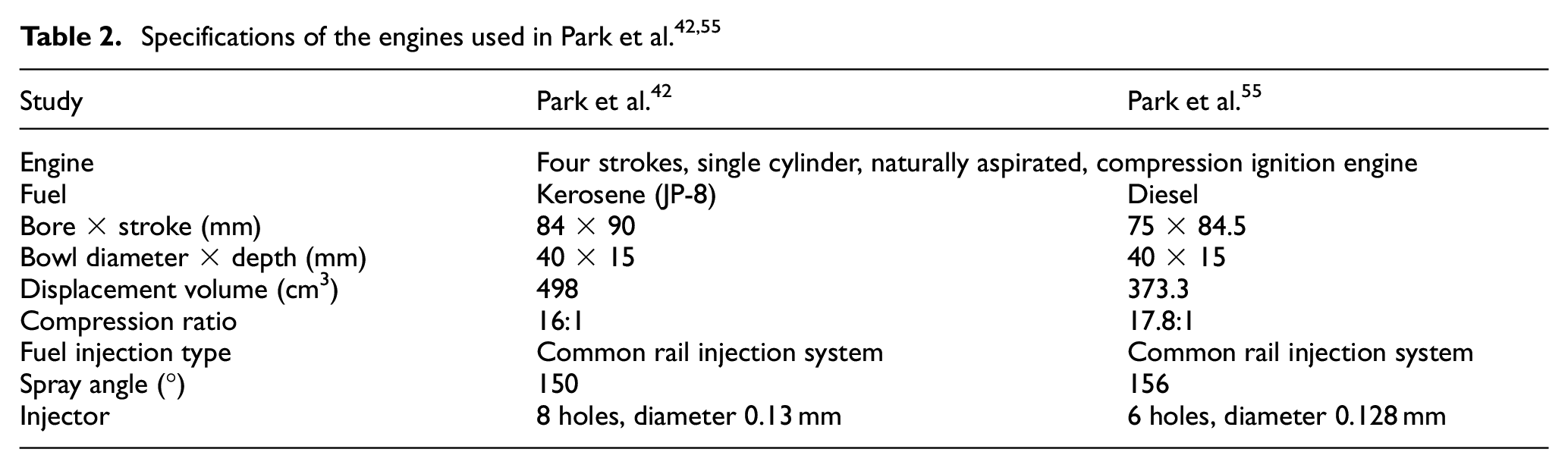
An initial swirl ratio of 2 at BDC is set in the simulation based on the results reported by Yoon et al. 70 In order to reproduce the RoI profile, the settings in the injection sub-model are manually adjusted to fit the experimental results from Park et al.,42,55 which use an injection pressure of 500 bar. A single injection strategy is tested in Park et al., 42 while single and double injection strategies are used in Park et al. 55 The comparison between the experimental 55 and simulated injection profiles were presented in Figure 1, while the single injection of Park et al. 42 is modeled with a triangular profile. The operating conditions and injection strategies are listed in Table 3.
Simulated operating conditions.
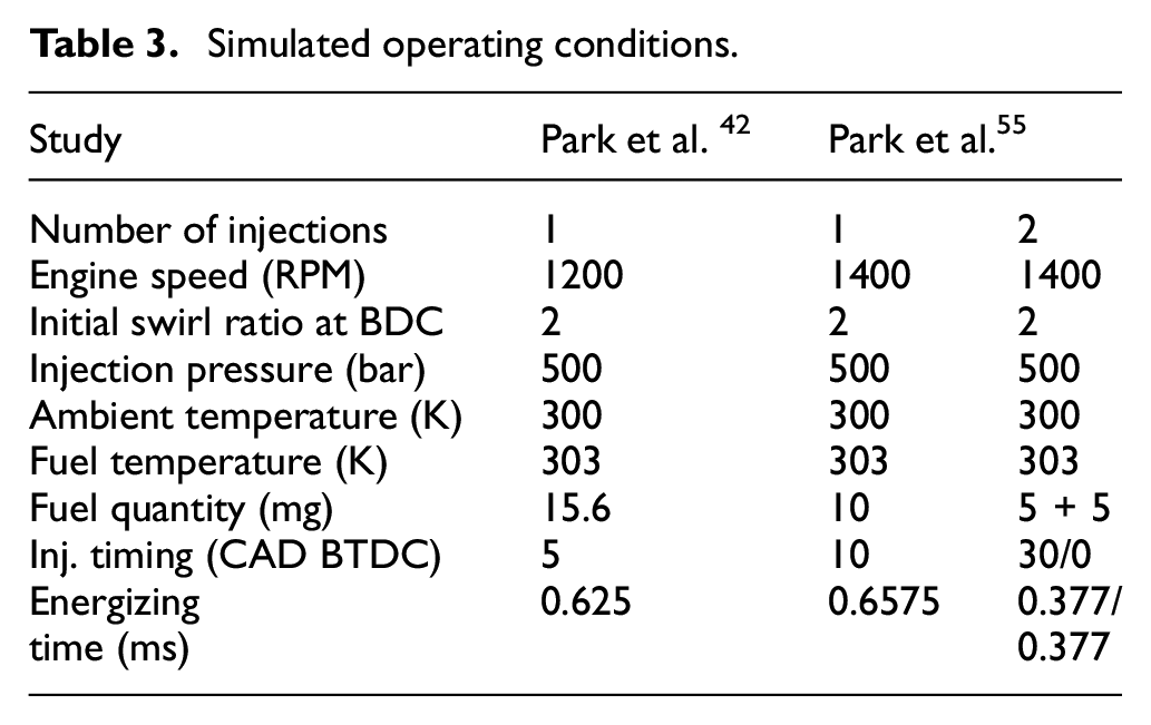
Figure 3 compares the experimental 42 and model results with kerosene, illustrating a good concordance with respect to the in-cylinder pressure evolution. It can also be observed (Figure 3– bottom) that the heat release rate (HRR) profile associated with the rapid combustion of the premixed phase is also well captured. The mixing-controlled and late combustion phases are predicted to be more intensive, resulting in a slight overprediction of the pressure during the early stages of the expansion stroke.
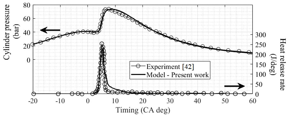
Comparison of the model predictions with the experimental data from Park et al. 42 obtained with kerosene.
The predictive capability of the model was also studied with several performance metrics. The discrepancy in the indicated mean effective pressure (IMEP) versus the experimental data from Park et al. 42 was of only 1.3%. Moreover, the calculated NO levels were overpredicted by 30% (1292 ppm vs 996 ppm in Park et al. 42 ), which is similar in terms of absolute error to the results reported by Hiroyasu et al. 20 and Jung and Assanis. 71 This discrepancy can be attributed to the limited modeling of the spray dynamics. 24 NO production is indeed highly sensitive to temperature, and a slight overprediction of the temperature can significantly increase the estimation of NO.
Another comparison was carried out between the experimental and CFD results from Park et al. 55 obtained with diesel fuel with a single (left) and a double injection (right) strategy, as shown in Figure 4. The figure shows in-cylinder pressure and normalized heat release and illustrates the capability of the model to reproduce a single or a double injection strategy.
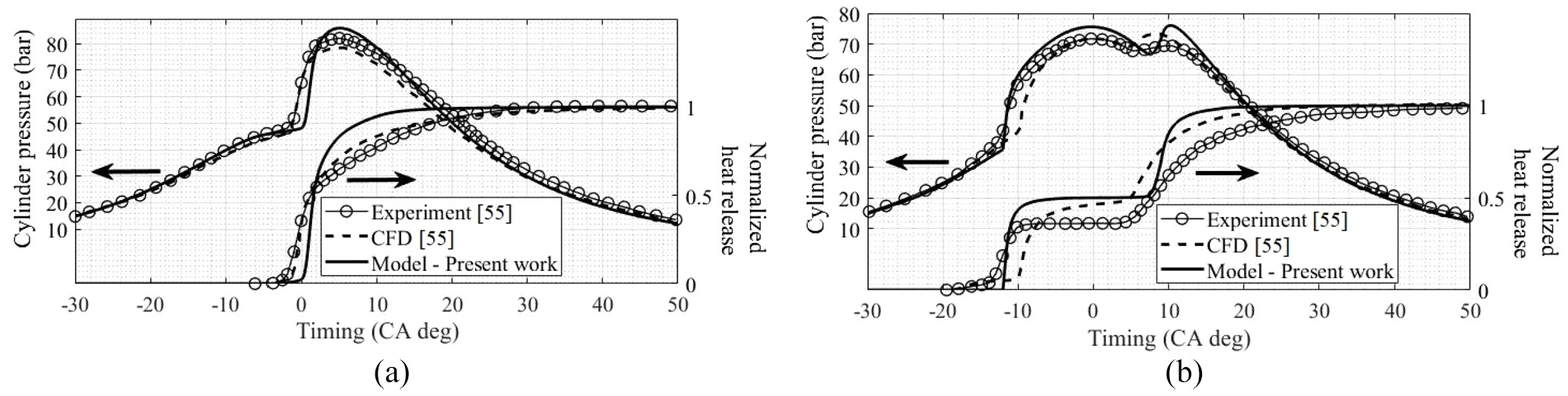
Comparison of the model with experimental and CFD data 55 using diesel fuel: (a) single injection and (b) double injection.
The results from the single and double injection configurations show that the start of the premixed combustion is slightly delayed with respect to the experimental results, and that the initial heat release is faster. The in-cylinder pressure profile during the expansion stroke in Figure 4(a) (single injection) is well predicted, with the location of maximum pressure matching the experimental results. When a double injection is analyzed (Figure 4(b)), it can be observed that the modeled heat release is faster as compared to the experiment, but that the ignition delay is better reproduced than with the CFD results. The figure suggests that the absence of a chemical kinetic in the proposed model does not severely impact the results in comparison to the CFD simulation. Both numerical models overpredict the pressure after the second injection. In, Park et al. 55 it is assumed that the first and second fuel injection profiles are identical although the cylinder pressure varies. The same approach is used herein with the proposed model, for which an overprediction of the heat release is observed as in Park et al. 55
Overall, the proposed model is able to predict the engine performance as well as the pollutant emissions and offers a good response to a change of the engine and injector design, fuel and injection strategy, showing its versatility. The model also demonstrates its scalability toward significant changes that are part of the engine design process for which the model has been precisely proposed.
Results and discussion
As the purpose of the proposed model is to offer a preliminary tool for engine design, different parametric studies are conducted in order to quantify the model’s response to predict the engine performance and emissions. First, the influence of the initial swirl ratio at BDC, in combination with the injection timing, is presented. Second, the effect of the piston bowl geometry is investigated. Third, the effect of adding EGR as well as the impact of its temperature is studied. Finally, the section concludes with a presentation of the effect of the fuel properties. All studies are based on the engine configuration of Park et al., 42 under the same load and speed as in the validation case.
Influence of the initial swirl ratio and injection timing
The influence of the initial swirl ratio (
Figure 5 presents the evolution of the instantaneous swirl ratio as a function of CAD. It can be observed therein that the swirl ratio remains fairly constant during most of the compression stroke, and then increases rapidly to reach a maximum value in the vicinity of TDC. Furthermore, it can be noticed that the higher the initial swirl ratio at BDC, the stronger the swirl motion in the cylinder at TDC.
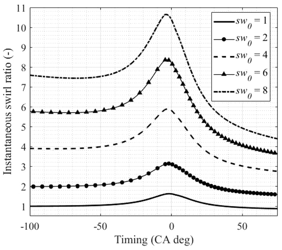
Influence of the initial swirl ratio at BDC on the swirl intensity near TDC.
The effect of the initial swirl ratio on the IMEP is shown in Figure 6 for different injection timings, ranging from −20 to 5 CAD ATDC, while the maximum brake torque (MBT) is obtained with an injection timing between 10 and 5 CAD BTDC. The general trend is for the MBT injection timing to shift toward TDC as the swirl ratio increases. This is consistent with the fact that a higher swirl ratio results in a more rapid premixed combustion. From an optimum injection timing, the model predicts a decreasing IMEP with delayed or advanced injection timing, as expected.
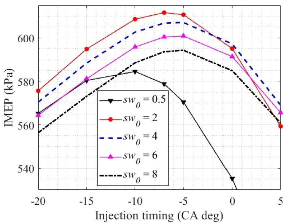
Combined influence of injection timing and initial swirl ratio on IMEP.
The influence of the injection timing and swirl ratio on NO formation is depicted in Figure 7(a). Injection timing has the effect of influencing the HRR with respect to the piston position, and to thus impact the in-cylinder peak temperature. Therefore, an early injection timing promotes a high peak temperature, which translates into a higher NO production, as can be seen in Figure 7(a). A swirl ratio between 2 and 4 offers a higher IMEP, but is also responsible for higher NO emissions. Nonetheless, if the injection timing is retarded until TDC, there is a risk of deterioration of the combustion if the swirl ratio gets too low due to spray-wall interaction resulting in increasing soot emissions (Figure 7(b)), and a significant reduction of IMEP is observed in Figure 6 (see
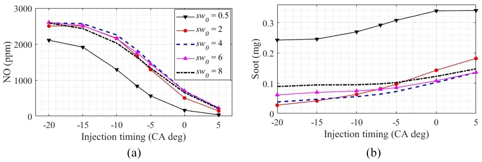
Influence of injection timing and initial swirl ratio on engine emissions: (a) NO and (b) soot.
Particulate emissions are the result of a poor oxidation of fuel-rich vapor regions. Hence, improving the air-fuel mixture by increasing the swirl from 0 to 4 results in lower soot emissions, as shown in Figure 7(b), with retarded injection timing. Moreover, a stronger swirling flow in the cylinder can also increase the soot emission as also reported in Gode et al. 72 Overall, the swirl effect at a constant injection timing follows the NO and soot trends reported by Benajes et al., 73 for a similar overall equivalence ratio of 0.36.
Piston bowl geometry
The previous calculations were performed with a piston bowl depth of 1.5 cm and a diameter of 4 cm, as presented in Table 2. In this section, the dimensions of the piston bowl are varied in order to allow an assessment of the capability of the model to be used as a design tool by conducting a parametric study. The ratio of the bowl diameter to the cylinder bore is varied from 35% to 80% by increments of 5%, while the bowl depth is correspondingly adjusted such as to keep the compression ratio unchanged. Figure 8 illustrates the cross-sectional view of three of the configurations tested with the piston at TDC while showing that the bowl depth decreases as the piston cavity widened.
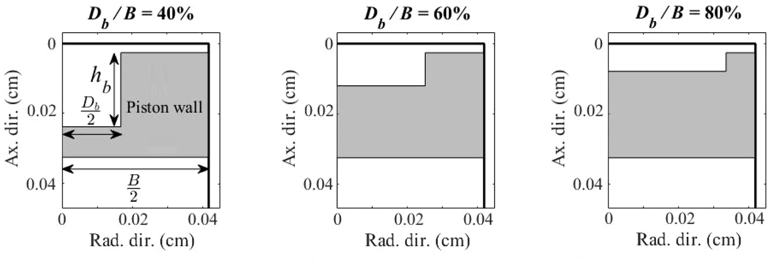
Piston bowl geometry for various
Simulations were carried out for six different initial swirl ratios varying from a weak
The impact of the bowl geometry on the instantaneous swirl ratio, for an initial swirl intensity of 2 and a constant injection timing of 5 CAD BTDC, is depicted in Figure 9. It can be observed that the swirl ratio increases in the vicinity of TDC as the bowl diameter decreases and its depth increases, which is in line with trends reported elsewhere.24,74 This trend is explained by the fact that a reduction of the bowl diameter is compensated by a swirl intensity increase in order to conserve the cylinder content angular momentum. The performance and emissions of the engine under the 60 configurations were gathered in the color maps presented in Figure 10.
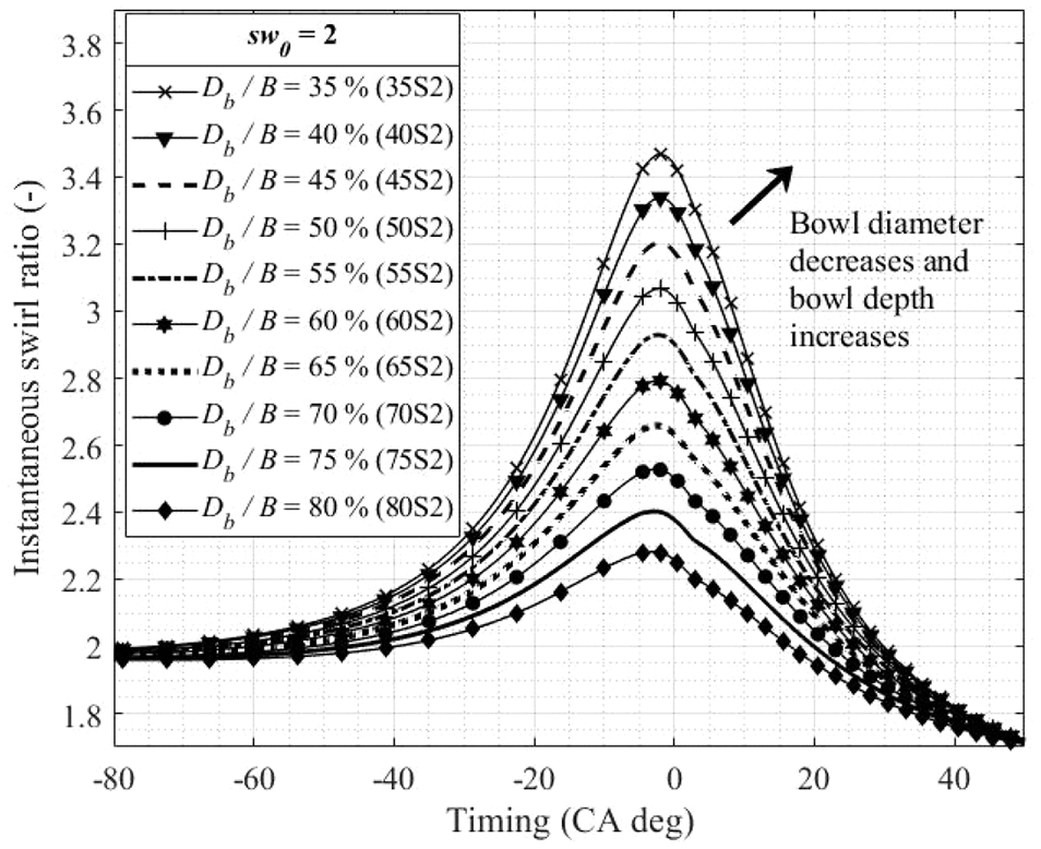
Influence of the piston bowl-to-bore ratio on swirl intensity (
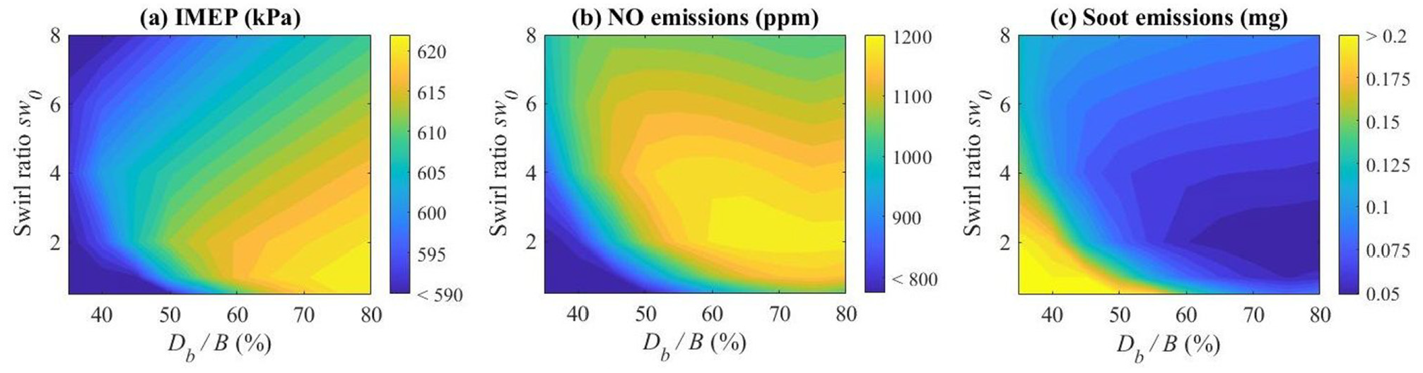
Combined influence of the initial swirl ratio and diameter ratio on: (a) IMEP, (b) NO emissions, and (c) soot emissions.
The IMEP is plotted in Figure 10(a) as a function of the diameter ratio and the initial swirl. It is observed that the output performance is maximized for a low to medium swirl in a range going from 1 to 3, and for diameter ratios greater than 55%. Wide bowl configurations are associated with a prevailing diffusion combustion, as observed in Figure 11(a) for configurations 65S2 and 80S2. Conversely, a diameter ratio of 50% promotes air motion in the cylinder, improving air-fuel mixing and the premixed combustion phase. Hence, the cylinder pressure of configuration 50S2 is higher during the first stage of the combustion (Figure 11(b)-inset left), but thereafter, remains below the cylinder pressure of larger bowl configurations (Figure 11(b)-inset right). Narrow bowl configurations (
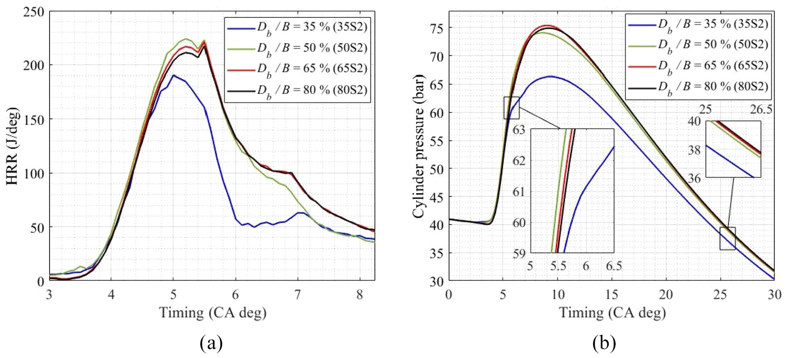
Influence of the piston bowl-to-bore ratio on: (a) HRR profiles and (b) pressure profiles.
Effect of EGR addition
The model is now used to study the impact of EGR addition and of its temperature on pollutant emissions.
Effect of the EGR rate
Two engine loads were simulated in order to compare the influence of the EGR rate on the performance and exhaust emissions: a low load (IMEP ∼6 bar, 1200 rpm) corresponding to the aforementioned reference case and a high load (IMEP ∼10 bar, 2000 rpm). In both cases, the injection timing was kept constant at 5 CAD BTDC. NO and soot emissions are presented in Figure 12(a) for both loads using a constant EGR temperature of 450 K. The increase in the EGR rate in the intake charge leads to a decrease in NO with increasing soot emissions as expected, illustrating the well-known tradeoff between NO and soot in the presence of EGR. 75 This trend is observed at both loads, although the decreasing rate of NO with increasing EGR is sharper at high loads and high EGR rates. The decrease in NO emissions results from a reduction of the local flame temperature due to changes in the specific heat of the mixture and to the decreasing availability of O2. Conversely, the soot formation increases due to the global enrichment of the gas mixture, as shown in Figure 12(b), as the injection duration is kept constant. The air-fuel ratio drops linearly with increasing EGR, resulting in a mixture enrichment. The net effect on the engine performance is also depicted in Figure 12(b). Indeed, the lower density of the inlet charge reduces the mass of gases trapped in the cylinder and deteriorates the volumetric efficiency. As a consequence, the maximum pressure reached in the cylinder drops (by 6% from no EGR to 15% EGR at low load), illustrating the negative effect of EGR on the engine IMEP. At high load, an increasing EGR has a greater impact on increased soot production and decreased IMEP than at low load (see Figure 12(a) and (b), respectively), suggesting that combustion degradation is greater with a lower air-fuel ratio, as reported in Jacobs et al. 76
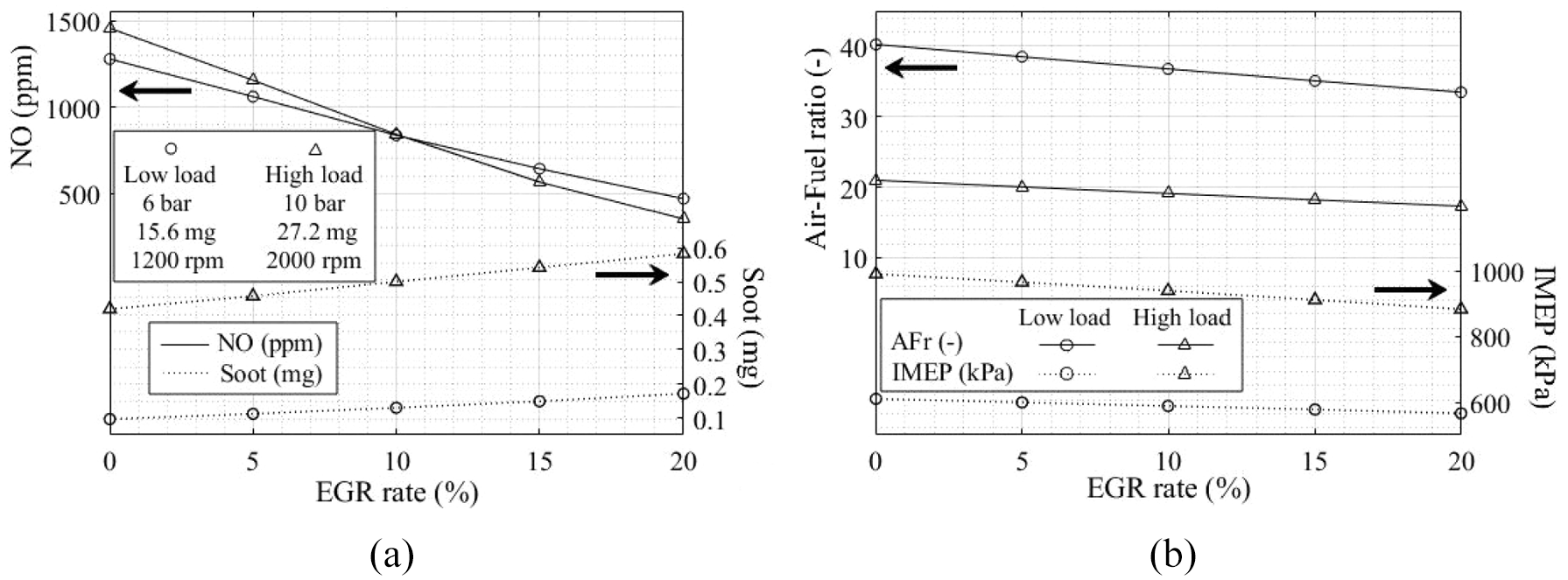
Effect of EGR rate at
Effect of EGR temperature
The addition of exhaust gases in the fresh air increases the mean in-cylinder gas temperature and lowers the volumetric efficiency. This thermal throttling effect 77 can be obtained either by increasing the EGR rate, as was done in the previous section, or by increasing the temperature of the EGR, as shown in Figure 13(a) for a constant 15% EGR rate. In the latter case, increasing the EGR temperature results in a slight fuel mixture enrichment and a reduction of the peak in-cylinder pressure. Overall, a drop by 6.8% of the engine IMEP is observed at low load when the EGR temperature increases from 350 to 600 K, as shown in Figure 13(a).
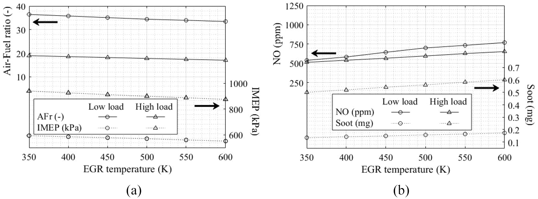
Effect of EGR temperature with 15% EGR using constant injection timing and fuel mass injected on: (a) performance and (b) pollutant emissions.
It is observed in Figure 13(b) that the use of a high temperature EGR (without cooling) has a negative impact on engine emissions at low and high loads as both NO and soot emissions increase. The rise of NO is primarily due to the higher maximum in-cylinder temperature reached when increasing the EGR temperature. Although a hot EGR also reduces the air-fuel ratio and limits O2 availability, the net effect observed in this study is a rise of NO, as also reported experimentally by Abu-Hamdeh. 78 On the other hand, the benefits on soot emissions provided by applying EGR cooling is due to O2 availability and the resulting higher air-fuel ratio, which contributes to the oxidation of soot. This supports the idea that a cooled EGR has a positive effect on the engine performance and pollutant (NO and soot) formation.37,79 Overall, the results show that the implementation of EGR with lookup tables in the model successfully predicts the effect of EGR addition to the fresh mixture on the engine performance and emissions.
Influence of three fuel properties
Finally, through a parametric study, the model is used to investigate the influence of three fuel properties on the engine performance by independently changing the lower heating value (LHV), the latent heat of vaporization (
Influence of LHV
The LHV of the fuel was varied by ±10% (cases 2 and 3 in Table 4), while the injection duration was accordingly changed so as to introduce the same amount of energy in the engine. The effect of injection timing is studied with cases 4 and 6, while the effect of swirl is covered by case 5.
Test cases for LHV influence.
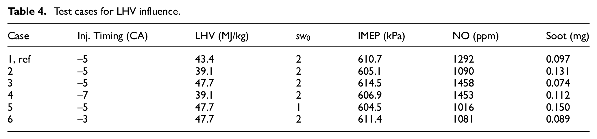
As can be seen in Table 4, a 10% decrease of LHV (case 2) leads to a 0.9% IMEP loss, unlike the more energetic fuel (case 3), which induces a slight gain of performance, but also results in a higher NO emission and lower soot due to a shorter injection duration when compared to the reference case and the low LHV fuel. The shorter injection shifts the heat release nearer to TDC, resulting in higher temperatures, as can be observed in Figure 14. The resulting trends observed for NO and soot emissions (Table 4) are in line with the experimental results of Desantes et al., 80 who studied the effect of the fuel injection rate on engine performance and emissions, and reported lower NO and higher soot emissions with an increasing injection duration.
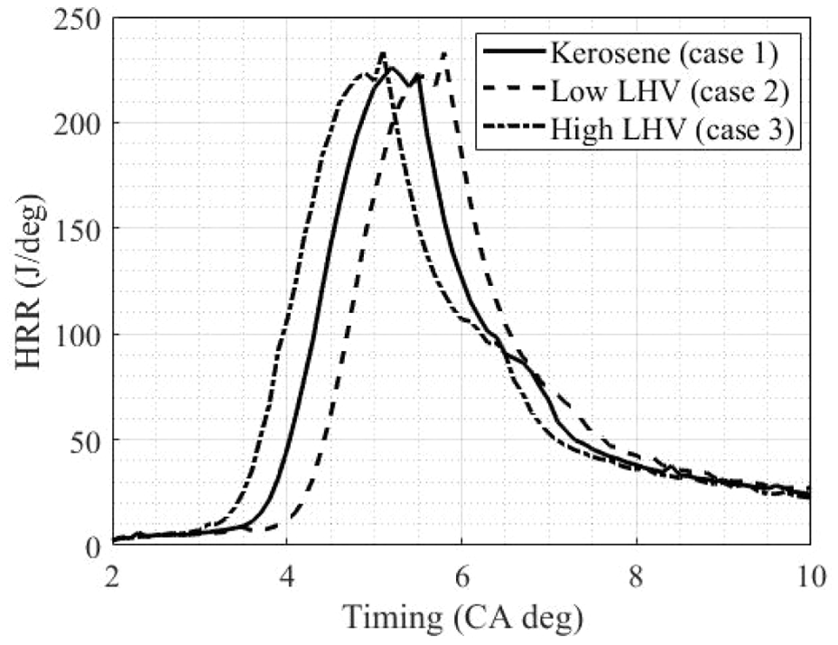
Influence of LHV on the HRR profile.
The loss of engine IMEP associated with a low LHV fuel can be partly compensated by using an earlier injection (case 4), but a significant increase in NO emissions is observed (Table 4, case 4) with a decrease in soot with respect to case 2. The higher LHV fuel was tested with a lower swirl (case 5) in order to impact the mixture formation process and to decrease NO. However, a decrease in IMEP and a significant increase in soot emission with respect to case 3 are observed. Finally, case 6 shows the interest of using a retarded injection timing with a high LHV fuel, allowing increasing IMEP, while simultaneously decreasing soot and achieving a lower NO emission than the reference case.
Influence of
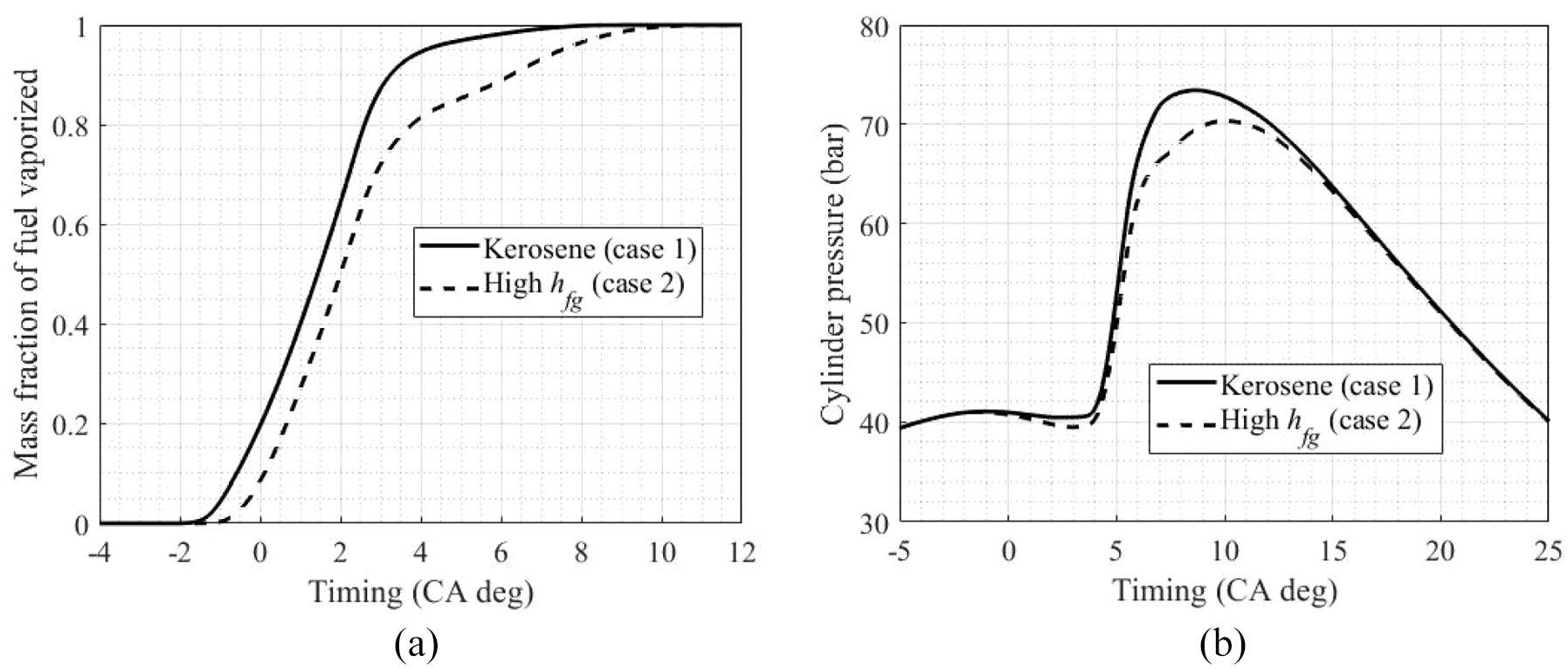
The effect of the latent heat of vaporization is studied by using a high
Test cases for
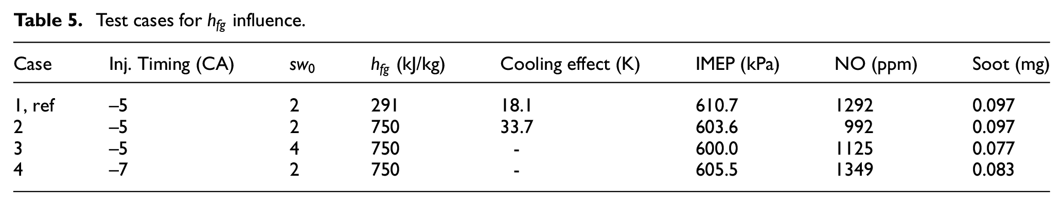
An increase of
Influence of
To compensate for the fuel air mixing decrease, case 3 investigates the impact of increasing the swirl intensity, which improves mixing but slightly increases NO emissions and decreases the soot and IMEP with respect to case 2. Advancing the injection timing (case 4) is a promising strategy to compensate for the observed decrease in IMEP while increasing
Influence of Tboil
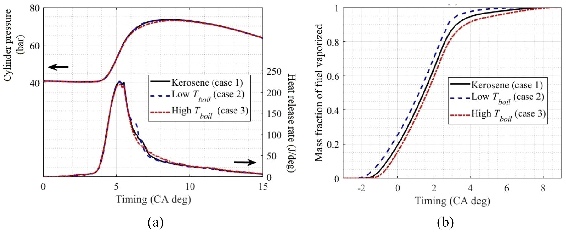
As a last step, the influence of the boiling temperature is studied through five test cases. They are reported in Table 6 which illustrates the range of
Test cases for
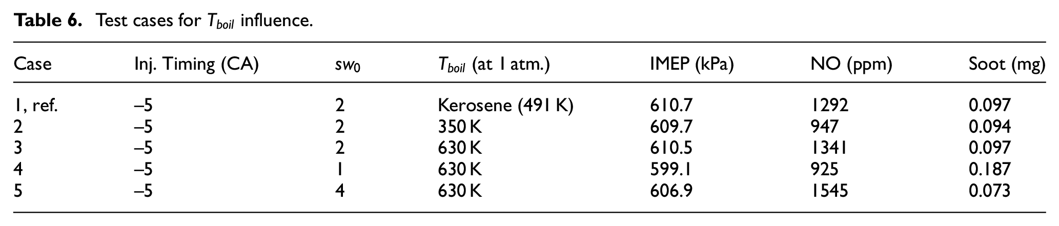
As can be seen in Table 6,
Influence of
Finally, the model has been used to simulate a fuel change by comparing B0, B50 and B100 using the kinetic of Diesel-biodiesel blends based on a ternary blend of methyl decanoate, methyl 5-decenoate and n-decane proposed by Chang et al. 82 General trends are in concordance with the literature with respect to ignition delay, heat release and NO emission. Nevertheless, and because the soot model used herein is insensitive to the fuel composition or structure,83,84 it will hence be updated in future works.
Conclusion
A single-zone phenomenological model of a compression ignition engine fueled with kerosene was proposed in this study. The predictive model includes a novel injection sub-model able to provide an input injection profile for a wide range of injection conditions and injection duration (short and long). This sub-model is coupled with a combustion model based on the spray packets concept, which can also interact with the swirling flow. Moreover, the model includes a thermodynamic database generated using a kinetic solver that allows quantifying the impact of EGR rates and temperature on pollutant emissions. This enhanced model was validated against experimental data and showed its capability to predict engine performance and emissions with single and double injections. A parametric study approach dealing with the injection timing and initial swirl ratio confirmed the trends from the literature, and allowed generating power output, NO and soot maps as a function of the piston bowl dimensions, thus confirming its usefulness in a preliminary engine design process. Furthermore, the results show that decreasing the EGR temperature is beneficial to decrease NO and soot emissions. Finally, three fuel properties were selected based on their wide range of values among the fuels studied in the literature. Varying LHV has a two-fold impact: first, it plays on the injection duration and second, it impacts the heat release rate. Retarding injection timing with a high LHV fuel allows decreasing emissions. Increasing the enthalpy of vaporization has a greater cooling effect that decreases IMEP and NO. Soot can be decreased by increasing the swirl ratio or increasing the injection timing, but IMEP remains lower than with a low
Footnotes
Appendix
Declaration of conflicting interests
The author(s) declared no potential conflicts of interest with respect to the research, authorship, and/or publication of this article.
Funding
The author(s) received no financial support for the research, authorship, and/or publication of this article.