
Abstract
Diesel engines continue to be used in truck applications, so reducing fuel use and hence CO2 emissions, is a priority. Single-stage turbocharged diesel engines are known to be fuel efficient under steady load at low speeds. However, the engine’s ability to track load transients becomes limited by emission constraints due to the rate of production values for smoke and the resulting higher nitrogen oxides (NO x ). Modern air-path solutions including a variable geometry turbine (VGT) and high pressure exhaust gas recirculation (EGR) can be used to improve dynamic response without increasing NO x emissions, but lead to complex interactions that can be difficult to control. This paper develops a two-stage, in-series, air-path configuration, which improves the typical part-load performance at low engine-speeds through adjustments to the turbine expansion ratios. Better EGR rates (for NO x reduction) at low engine speeds can be achieved whilst the engine transient response is maintained. The air-path system is simulated using Ricardo Wave software and analysed for steady-state and transient behaviour in order to identify the relationships, constraints and performance measures for different operating regions that specify the controller requirements.
Introduction
The diesel engine is a mature technology for vehicle propulsion. With the focus on carbon reduction, there is a move away from fossil-fuel engines to electric vehicles (EV). However power scale-up of EV systems for use in trucks is proving challenging, so increasing diesel engine fuel efficiency remains a priority.
Turbocharged engines have higher combustion pressure than naturally aspirated engines. The higher combustion pressure improves the thermodynamic efficiency of the compression ignition cycle.1,2 Experimental studies3,4 on down-speeding have shown improved fuel efficiency of about 12%–14% over separate transient drive cycles. To prevent performance loss at lower operating speeds, appropriate forced-induction is necessary. In order to avoid complexities associated with turbochargers’ dynamics, the studies3,4 propose reconfiguration of the air-path for induction by superchargers. Superchargers are directly energised by the engine crank shaft action, and thus induce air in proportion with the engine speed without introducing significant delays. Using superchargers results in a deterioration in fuel economy due to parasitic losses from the crankshaft.
Turbochargers are more energy efficient as they recover the available enthaply in the exhaust gas. However, they introduce delays to the air-path due to gas compressibility and mass inertia during load transients; these sharply reduce the fresh air intake and cause the engine smoke controller to limit the fuel supply as well. This results in slow engine torque response known as turbo-lag. 5 Engine performance margins at low operating speeds depend largely on torque availability.
Various configurations of turbocharged air-path have been suggested for air availability at intake and minimising nitrogen oxides (NO x ) values.6–13 These configurations are studied for modelling, dynamical analysis and control.5,14–16 Depending on the application, a configuration may include waste-gates, variable-geometry turbines (VGT), exhaust-gas recirculation (EGR), variable-geometry compressors and multi-stage turbochargers in-series or in-parallel. 17 The use of multiple air-path components introduces non-linear interactions that can be difficult to control.
By contrast with spark ignition engines, diesel engines and particularly heavy-duty diesel engines that have large inertia (often coupled with large inertial loads), only tolerate a relatively narrow operating speed range. This limits the pressure ratio that a single-stage compressor can produce as its induction depends on the engine pumping action harnessed via the turbine within that narrow engine speed range. As a result of this the compressor has to be large enough to be able to supply the necessary air at the intake for the entire operating range of the engine. A large compressor has large inertia, which demands higher exhaust-gas expansion ratio on the turbine side to speed up. Turbine expansion ratio is limited at low engine operating speed. The two-stage turbocharging can be used to increase the exhaust gas expansion ratio and improve the diesel engine thermal efficiency. 18 Matching the two-stage in-series regulated turbocharged system with the engine is challenging and is predominantly done by combining the turbochargers empirically.7,9 The combined system is usually optimised for full-load operation, compromising the part-load operation at low speed conditions where the limited available expansion ratio has to be divided between the turbines. 1 Diesel engine applications with two-stage in-series turbochargers that require more flexibility in operating speed range need to be regulated when they enter operating conditions that the turbochargers’ characteristic maps do not cover. 19
The air-path concepts outlined in this paper can be gleaned from the engine literature. The main contribution of this paper is the analysis of how multiple components interact and the consequent definition of controller requirements, in line with the goal of improving the part load performance of two-stage in-series turbocharged air path for realisation of engine down-speeding. A control strategy that covers these requirements is proposed and verified. 20
Towards this goal, the simulated standard single-stage turbocharged diesel engine plant and modifications are described in detail. The base engine model is available in the Wave software example engine library. It is a 1-D computational fluid dynamic (CFD) model, which is sufficiently realistic for analysis compared to lumped-parameter (mean-value) models. It is sufficiently simple allowing faster simulations compared to 3-D models and it is sufficiently generic. The steady-state performance measurements of single-stage and two-stage turbocharged systems at low engine speeds are compared. This is then followed by behaviour analysis of the two-stage air-path configuration with respect to change in engine operating conditions. The important requirements for control are discussed.
Single and two-stage air-path models
A baseline single-stage diesel engine is presented first and compared with the proposed two-stage in-series model. The models are then used for simulations in the next section.
Diesel engine with standard turbocharged air-path
A generic truck diesel engine model with standard single-stage turbocharged air-path (Table 1) available under the name ’dies6load.wvd’ in Ricardo Wave 1D-CFD engine simulation software is modified and used for simulations. The compressor map of the original model is selected to ’turbo.tcc’ and the turbine map to ’turbo.tct’.
Base engine and additional components specifications.
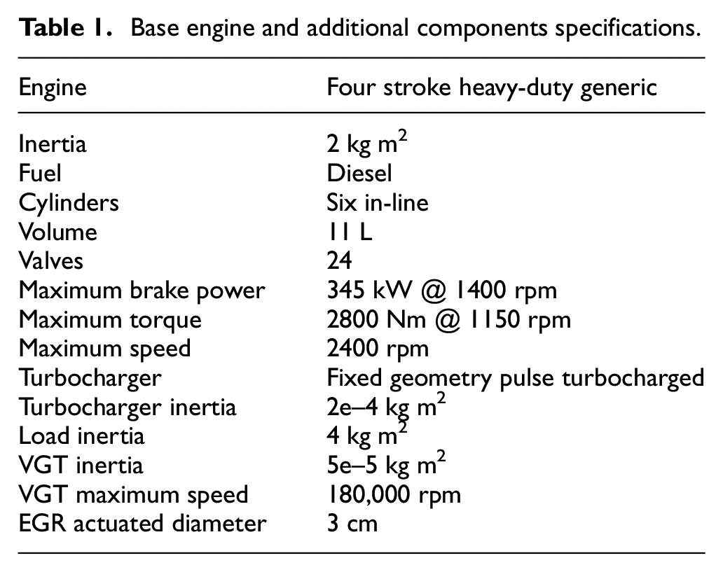
The engine is coupled to an adjustable load, both operating at the same speed. If the load and the engine were to operate at different speeds then a gearbox is necessary. Figure 1(a) displays the base engine construction in Wave.
(a) Single-stage pulse turbocharged baseline engine simulated in Ricardo Wave engine software and (b) abstract representation of the single-stage turbocharged air-path of the engine.
The single-stage standard air-path model in Figure 1(a) is composed of: a fixed geometry turbocharger that meets the air-supply requirement for the entire engine operating range. The turbocharger is not controlled. There is no external EGR path and the engine has a speed governor with smoke limiter. The volumes of the connecting ducts are included in the model. The model includes the effect of temperature. Figure 1(b) gives a schematic representation of the air-path.
Two-stage in-series turbocharged air-path
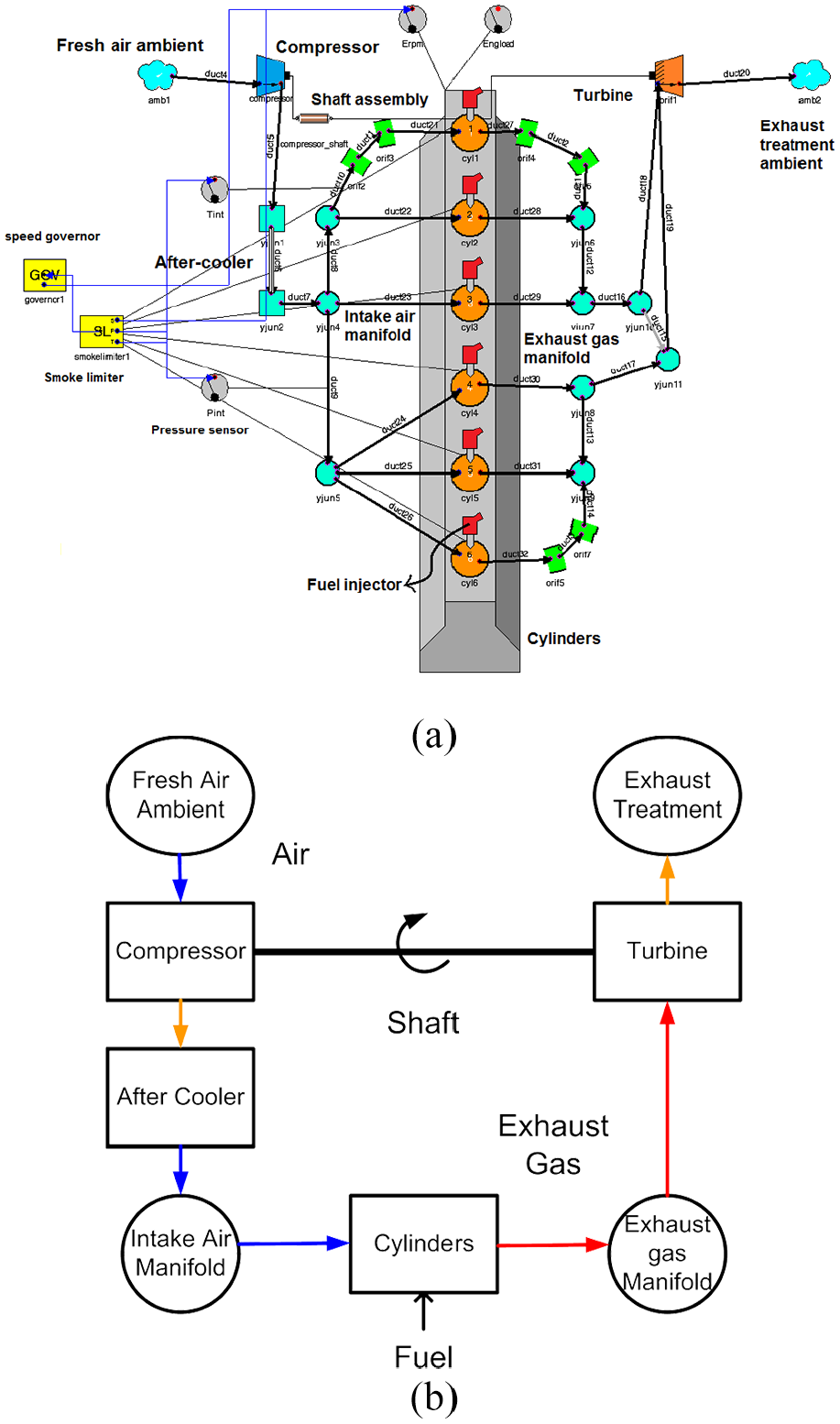
The single-stage air-path system of the baseline engine is modified to a two-stage in-series turbocharged path with NO x reduction capability (Figure 2(a)) by adding a high pressure (HP) stage VGT turbocharger (assembeled using ’asc14950’ compressor map and ’ns111’ VGT map of Wave software library) and a HP EGR path (Table 1). The VGT extends the air supply range to the engine’s low-speed operating region. The resulting air-path system is generically similar in configuration to the modified and simulated Caterpillar 3126B 6-cylinder engine air-path. 15 Additionally, the new configuration includes bypass valves for the HP and low pressure (LP) compressors (C), a bypass valve for the HP turbine (T) and a wastegate for the LPT. Following EGR inclusion, ideal reed-valves are utilised to maintain the split exhaust manifold function for pulse turbocharging benefits. Figure 2(b) displays an abstract overview of the modified air-path.
(a) Two-stage pulse turbocharged engine with VGT and EGR path operated in Ricardo Wave engine simulation software and (b) abstract representation of the two-stage turbocharged air-path.
The addition of the HP EGR system between the exhaust and intake manifolds reduces NO x by recirculating the cooled exhaust-gas matter (which has higher specific heat capacity than air) back into the intake. 8 The EGR flow also leads to reduced volumetric and fuel efficiency.
After the addition of the HP stage turbocharger in-series, the original engine’s fixed-geometry turbine turbocharger is now referred to as the LP stage turbocharger. The HP stage turbocharger is smaller than the LP stage turbocharger. It has a VGT that allows for power ratio control between the HPT and LPT through adjustments to its effective flow area. This also allows for the turbine power output to be maintained while its mass flow and the pressure ratio drop.
Bypass valves are required when the engine’s induced flow exceeds or falls short of the operating range of the HP and LP turbines and compressors. The use of the original engine’s fixed-geometry turbine at the LP stage of the air-path is consistent with the literature, 21 where it is shown that a LP stage VGT has no significant advantage over the fixed-geometry turbine at low engine speeds. For an optimum performance, the air-path needs to actively interact with the engine. The interactions are constrained.
The proposed system requires the control of pressure distribution between turbochargers via adjustments to the VGT, HP and LP bypass valves and the amount of EGR flow, in addition to the fuel flow control and smoke limiter present in the single-stage system.
Simulation of down-speeding
The Wave models in the previous section will be used to demonstrate the benefits and detriments of down-speeding and develop the proposed two-stage in-series turbocharged air-path as one way of realising it. Resulting interactions and control challenges will be highlighted.
Single-stage down-speeding
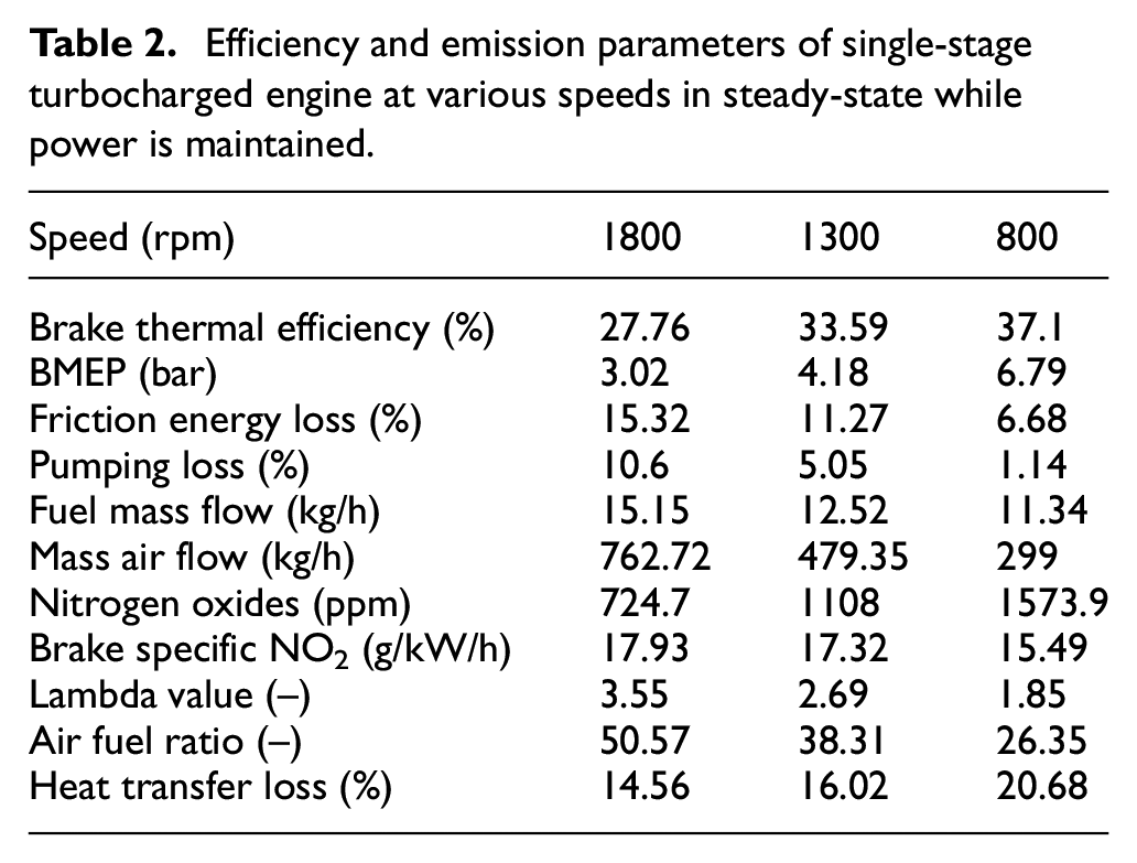
To exhibit the impact of lowering the operating speed on the engine’s efficiency and emission parameters, the engine with standard single-stage turbocharged air-path in Figure 1(a) is operated at three selected steady speeds of 800, 1300 and 1800 rpm under 50 kW of steady load. The speed governor is set to maintain the engine’s speed at each of the selected values. The speed points are arbitrarily chosen to represent the higher, middle and lower operating speeds of the engine. The engine parameters investigated are listed in Table 2. The choice of load must permit a comparative observation of the engine’s stable behaviour at the selected operating speed points. This means the choice of the load power must not exceed that of achievable engine brake power at the lowest operating speed; otherwise, the engine stalls and a comparative analysis is not feasible. Consequently, this load is significantly less than the engine’s maximum brake power in Table 1. The simulation results can be compared from Table 2. Reducing the operating speed decreases the parasitic losses due to friction.3,4 This in turn improves brake thermal efficiency despite the increased losses due to heat transfer. This increase in heat transfer loss is because the resulting hot gases from the combustion process at low engine speeds have more time to exchange heat to the surrounding cylinder surfaces. In the absence of an EGR path in this configuration, higher values of NO x in the exhaust are evident during low speed operation. This is a consequence of higher cylinder temperatures due to higher amounts of fuel burnt per stroke at higher cylinder pressures necessary for a higher engine torque to maintain the engine output power. As a result of higher fuel quantities per stroke, the air-to-fuel ratio (Lambda) falls. This reduces the engine’s torque attainability margin as Lambda value has moved closer to the smoke-limit. Torque attainability margin is the amount by which the engine torque can be increased at a given operating speed without violating the smoke production limit.
Efficiency and emission parameters of single-stage turbocharged engine at various speeds in steady-state while power is maintained.
Single and two-stage engine load transient response
The next simulation compares the load acceptance of the engine with the single-stage and two-stage turbocharged air-paths at low operating speeds under similar test conditions. Figure 3(a) and (b) display the engine response to a step load increase (Figure 3(c)) from 50 kW to 100 kW at the simulation operating speeds of 800, 1300 and 1800 rpm for the single-stage and two-stage air-paths respectively. A step load can be applied by defining a load-torque time profile in load model panel of Wave software. The load-torque needs to be calculated for the load-power of interest at each operating speed. The operating speeds are scaled to 1 for clarity in comparison. This simulation is in the absence of EGR disturbance effect.
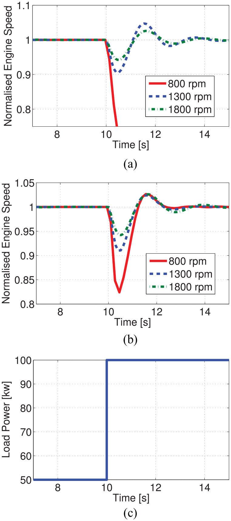
Normalised speed response of the engine with: (a) single-stage, (b) two-stage turbocharged air-path configurations, to a step load increase, and (c) from 50 kW to 100 kW.
Once the 50 kW step load is applied, the engine speed deviates from its set-point causing the speed governor to compensate. This results in a damped oscillation in the engine speed displayed in Figure 3. Due to insufficient air induction by the single-stage turbocharged air-path, the engine speed deviation at 800 rpm forces the governor to exceed the fuel-to-air ratio limit of 0.065, enforced by the smoke limiter on the fuel supply, and as a result the engine stalls (Figure 3(a)). In the engine simulation with two-stage in-series turbocharged air-path, the VGT rack position that sets the HPT flow area is set to 50% for 800 rpm – to supply sufficient intake air flow that is much needed at this engine speed. The VGT is set to 100% for 1300 rpm – to prevent the turbine choke flow condition that may result in exhaust manifold back pressure. The HP stage is entirely bypassed at 1800 rpm as the mass flow induced by the engine far exceeds the HP stage turbocharger’s operating range. Therefore, the two-stage configuration is irrelevant at high engine speeds. To bypass the HP turbocharger, both the HP stage VGT turbine wastegate and the HPC bypass valve are entirely opened. As shown in Figure 3(b), the engine no longer stalls at 800 rpm under similar load increase. The combined induction of LPC and HPC increase the intake manifold air density resulting in higher air mass flow aspirated by the engine. Following the step load at 800 rpm, the engine speed drops by 17.5% and recovers within 5% of the steady state speed in about 1.1 s. The time constant of the engine’s speed transient response to changes in load presented in Figure 3 depends on the value of the load inertia. This means for similar step load increase at each of the speed points, the waveform (engine speed response) changes with change in load inertia.
Constrained interactions of the two-stage turbocharged air-path
The improved step load response of the two-stage turbocharged engine operating at 800 rpm is a result of adequate aspiration that was not feasible with the single-stage turbocharger. The two-stage in-series turbochargers extend the air-path system’s operating range with respect to the engine’s torque-speed operating envelope. This extended range is the result of distinct physical properties (e.g. size and inertia) of each turbocharger. The intersection of the turbochargers efficient operating regions with each other and with that of the engine is desirable. However, as the engine operating condition is varied beyond this intersection region, saturations and inefficiencies are inevitable and may limit the engine top performance. The operating conditions that lead to these saturations and their impact are shown here.
Figure 4(a) and (b) show the pressure ratio and speed values of the HPC and LPC before and after a 50 kW step load increase at the engine speed of 800 rpm. The improved engine response at 800 rpm in Figure 3(b) is mostly dominated by the HP stage turbocharger’s faster dynamics, as the LPC is barely responding to the step. The LPC speed moves from 23,500 rpm to 33,000 rpm, while its pressure ratio is changed from 0.95 to 1.05. The HPC speed moves from 143,000 to 188,000 rpm, while its pressure ratio is changed from 1.6 to 2. Here, although the open loop air-path behaviour has led to improved engine response, the compressors’ responses indicate two unfavourable conditions: the LPC redundancy prior to the step and the HPC choked flow operation after the step. A pressure ratio of <1 indicates that the compressor is not applying any work to the flow, that is, it is redundant. Evidently (Figure 4(a) and (b)), this is the case for the LPC at the operating point (800 rpm, 50 kW) prior to the step load. This is caused by insufficient gas-flow at the LPT, while the sufficiently energised HPC is inducing higher airflow and creating a vacuum in the space between the compressors, that is, the power is not properly distributed between the two stages. The situation changes once the step load is applied and the engine moves to another operating point (800 rpm, 100 kW).
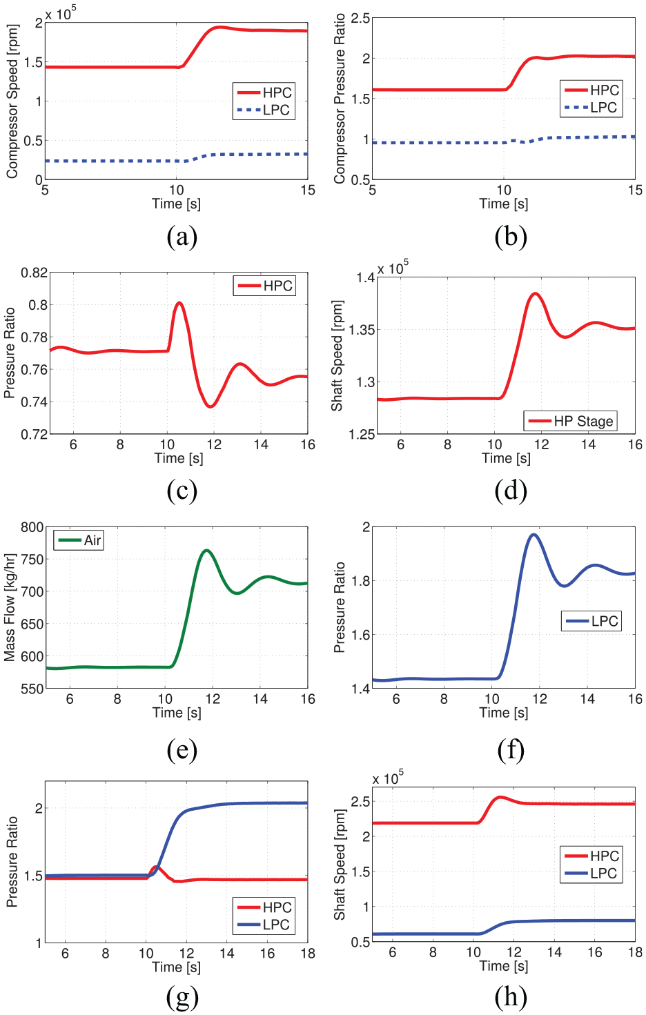
Compressors’ response to 50 kW step load increase from 50 kW to 100 kW at 800 rpm: (a) HPC and LPC speed response, (b) HPC and LPC pressure ratio. Compressors’ response at the engine speed of 1800 rpm: (c) HPC pressure ratio, (d) HP stage shaft speed, (e) LPC mass flow, (f) LPC pressure ratio. HPC choked flow step response at 1300 rpm: (g) HPC and LPC pressure ratio, and (h) shaft speed.
To highlight the importance of managing the power split between the two turbochargers, Figure 4 also shows the engine at a higher speed for the same 50 kW to 100 kW load step. The mass-flow induced by the upstream LPC (Figure 4(e)) exceeds the flow capacity of the downstream HPC, dropping its pressure ratio (Figure 4(c)) while LPC pressure ratio increases (Figure 4(f)). Here, prior to the step load, the engine is operating with the HP stage VGT position open at 100%, its waste-gate at 20%, and the compressor pressure ratio is about 0.77. The HPC pressure ratio is <1 and drops even further following the step load increase despite the resulting increase in HP stage shaft speed. The shaft speed response in Figure 4(d) shows that the HPC pressure ratio of <1 is not due to choked flow condition, since the shaft speed remains less than the maximum speed of 180,000 rpm before and after the step load. This condition is inefficient and needs to be managed. It can potentially force the LPC to stall and surge.
Following the step load in Figure 4(a) the shaft speed has exceeded the maximum limit that the HPC is rated for and as a result the HPC flow is slightly choked. To better demonstrate this behaviour the engine operating speed is moved to 1300 rpm. Figure 4(g) and (h) show the HPC pressure ratio does not significantly change with the change in shaft speed following the step load. To manage this condition, the shaft speed needs to be regulated through action on the HPT bypass valve or on the VGT position. Figure 5(a) and (b) show how the transient profile moves along the compressor maps.
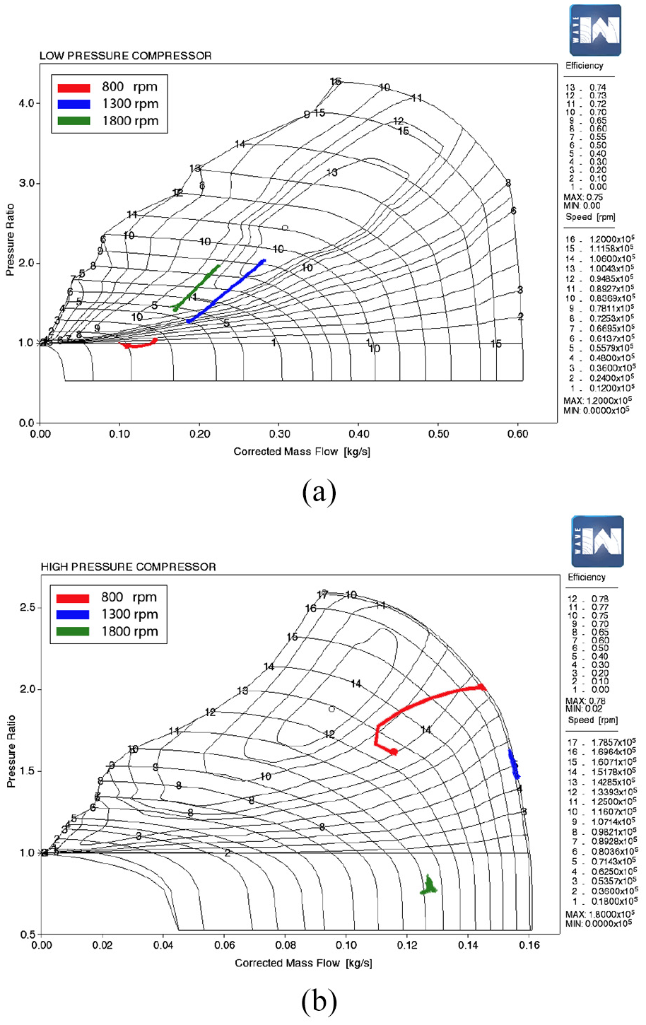
Step transient profile at 800, 1300 and 1800 rpm on compressor maps: (a) LPC and (b) HPC.
This simulation clarifies that the extracted power (via turbines) from exhaust enthalpy has to be distributed between the turbochargers based on the shared exhaust mass flow and the expansion ratio across the turbines defined by the engine operating point and the constraints imposed by the compressors’ respective operating ranges.
VGT adjustments and bypass-valve regulations
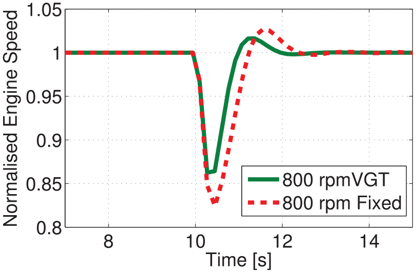
Using VGT adjustments, the extracted power can be appropriately distributed between the LP and HP turbochargers. This is achieved through adjustments to the turbine’s flow area that permits changes in the HP turbocharger’s shaft speed for a given exhaust gas flow. This ability in turn allows for further reduction in the engine operating speed as the intake airflow can be maintained before and after a change in load. Figure 6 compares the 50 kW step load response of the HPC when the VGT position is fixed and when the VGT is adjusted with the change in load. As a result of VGT adjustments, following the step load, the shaft speed (Figure 6(b)) and the compressor pressure ratio (Figure 6(a)) remain under the choked flow condition (compressor choked flow speed of 180,000 rpm) before and after the step load. The VGT maintains higher shaft speed and thus higher compressor pressure ratio prior to the step load, resulting in more air availability. This is critical to achieving feasible peak air-to-fuel ratio at low engine speeds, especially, following a step load that may cause a drop in the engine speed before the governor action could compensate for the deviation.
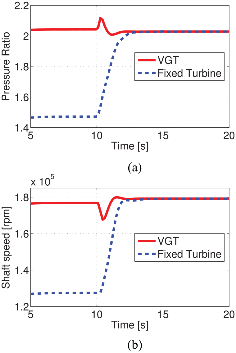
HPC in the absence of EGR disturbance effect: (a) pressure ratio and (b) speed, response with and without VGT adjustments, at engine speed of 800 rpm and 50 kW load followed by 50 kW step.
The peak amount of the engine speed deviation (drop) following a step load at low engine-speeds (Figure 3(b)), depends on the VGT position at the time the step load is applied. For example, Figure 7 shows the speed deviation decreasing to 13.75% from previously 17.5% for the same step load at 800 rpm, after the VGT position is reduced by 20%. Finding optimal VGT positions throughout the engine operating envelope is an important step towards achieving an efficient and stable down-speed engine operation.
Improved normalised engine-speed response (with 20% VGT adjustment in the two-stage air-path configuration) to 50 kW step load increase.
EGR interaction
The two-stage in-series turbochargers increase the exhaust manifold pressure and hence improve the EGR flow at low engine speeds.11,12,22 Actuating the EGR flow slows down the turbochargers’ shaft speed, that is, it leads to less compressor induction. The amount of EGR flow depends on the pressure difference between the exhaust and intake manifolds as well as the flow area of the EGR path. Adjusting the EGR valve flow area affects the oxygen concentration at intake which in turn influences the NO x amount in the exhaust gas via resulting changes in combustion temperature.
Figure 8(a) and (b) present the effect of change in the EGR valve diameter on the engine speed response with 50 kW load at 800 rpm to a 50 kW step load, when the VGT position is fixed at 70% and the LPC of the two-stage air-path configuration is bypassed. Figure 8(a) shows the gradual deterioration of the engine speed tracking performance as the EGR valve diameter is increased. Note that the engine stalls at EGR diameter of 2.5 cm once the step load is encountered. Prior to and after the step load transient, the NO x values decrease as the EGR diameter is increased (Figure 8(b)). However, during the load transient, increased NO x production rate (inevitable due to more fuel injection) is prolonged as the EGR diameter is increased.
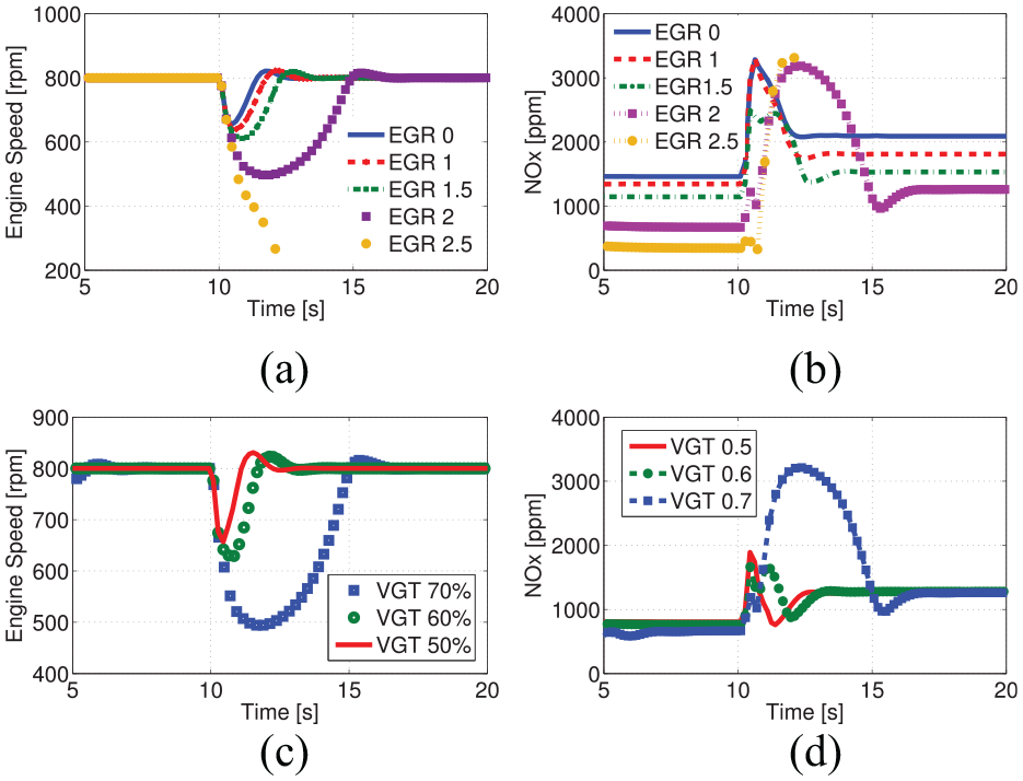
Effect of change in the EGR valve diameter (in cm) on the engine speed response to a step load when the VGT position is fixed: (a) engine speed, (b) NO x values. Effect of VGT position on (c) the engine speed response as the VGT position is decreased from 70% to 50%, and (d) NO x production.
Under similar conditions, the effect of change in the VGT position on the engine speed response is investigated. For this, the EGR diameter is fixed at 2 cm, where the engine previously showed a poor speed tracking performance just before it stalled. Adjusting the VGT position down to 50% improves the speed tracking significantly (Figure 8(c)), and increases the EGR flow during the step load transient suppressing NO x peak production rates (Figure 8(d)). The reduction in VGT position will rapidly increase the exhaust manifold pressure, increasing the EGR flow rate during the step load transient. This is while the HPT is speeding up. The resulting higher EGR flow is of short duration and reverts back as the intake manifold pressure is raised in response to higher turbocharger speed. Note that the maximum EGR flow is capped by the exhaust and intake manifolds’ pressure difference, while the minimum EGR flow is set by the EGR valve position. Lower EGR downstream pressures at the intake manifold can be maintained for higher EGR flow rates using an EGR throttle-valve, positioned at the outlet of the HPC. Lower amounts of intake manifold pressure are achieved by restricting the inflow from the compressor. However, actuating the EGR throttle-valve must not cause compressor surge. 23
It seems reasonable to close the EGR path swiftly to achieve maximum turbochargers’ speed during heavy load transients. This improves speed tracking performance and helps to avoid excessive NO x production due to prolonged load transient time. A rapid closure of the EGR creates transients in the pressure values and the oxygen concentration, at the intake and the exhaust manifolds, as well as the turbochargers’ shaft-speed. In particular the intake manifold pressure shows a sudden drop in pressure before reaching higher values as shown in (Figure 9(a)). This represents a significant disturbance in the control. Figure 9(b) shows the higher rate of NO x when EGR remains closed.
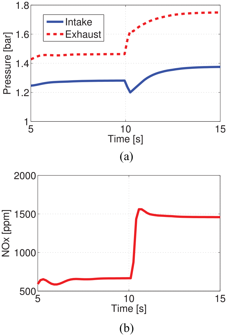
EGR-closure effect on: (a) the intake and exhaust manifolds’ pressures and (b) NO x production, when the engine is under 50 kW constant load at 800 rpm.
Implications for controller design
The simulation results in the previous section have demonstrated that two-stage in-series turbochargers improve performance at low speeds (Figure 3(b)). However, they also complicate the interactions between the engine and the air-path by increasing the degree of freedom.
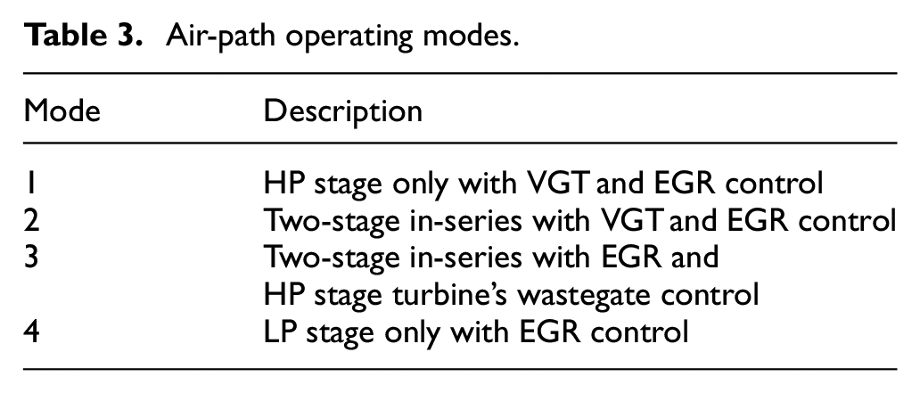
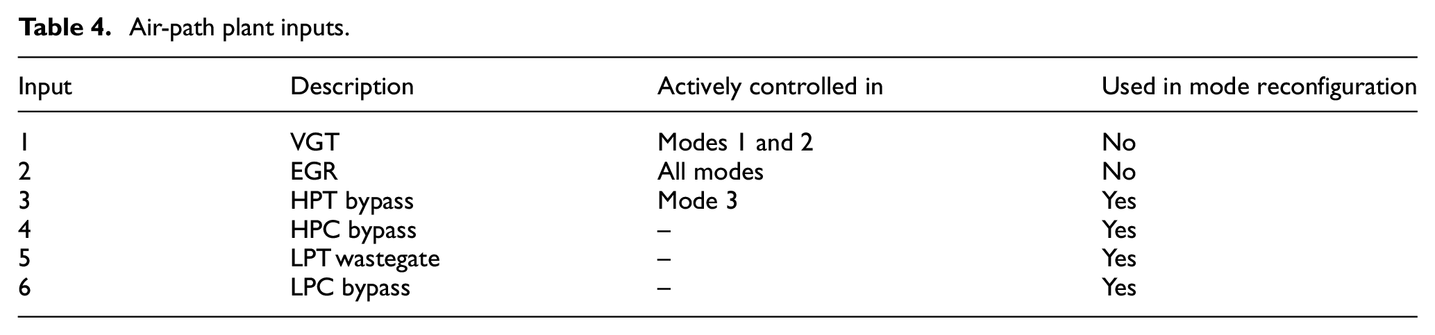
The following conditions have been shown to saturate the system and/or lead to inefficiencies and loss of performance: (1) HPC choked flow operation (Figure 4(g) and (h)). This is an energy inefficient operating condition at medium to high engine speed when the compressor exceeds its maximum speed and stalls. (2) LPC redundancy (Figure 4(a) and (b)). This condition leads to unnecessary exhaust gas pressure ratio split between the turbines at low engine speed, limiting the HP turbocharger’s effectiveness. (3) HPC redundancy at high engine speed when the flow induced by the LPC exceeds the HP stage limit (Figure 4(c)). This can potentially force the LPC to stall and surge. These air-path operating conditions are encountered as the engine operating point varies with respect to changes in load. In order to avoid them, the air-path needs to be actively reconfigured into one of the operating modes in Table 3. This can be done using bypass valves and wastegate actuations (Table 4 and Figure 2(b)). Peak performance throughout each operating mode can be maintained via adjustments to the VGT and/or EGR valve positions. The HPT bypass valve is used for configuration management as well as shaft speed control in operating mode 3. The VGT input is only relevant in operating modes 1 and 2. The EGR input is used in all operating modes. The air-path at each operating mode is structurally different with separate characteristics and dynamical properties. This forms an overall hybrid dynamical system, exhibiting both continuous (within each configuration) and discontinuous (jumping between configurations) dynamic behaviour. Furthermore, since air-path reconfigurations occur as a result of change in the engine’s operating conditions (speed and load), the air-path control objective inevitably changes. For example, the adverse effect of EGR flow on the engine load transient response that is observed during low speed operations becomes insignificant at higher engine speeds when the exhaust flow is abandoned and the manifolds are well pressurised. Consequently, irrespective of control strategy, each air-path configuration poses a distinct control problem. Thus, there are control system boundaries.
Air-path operating modes.
Air-path plant inputs.
How to clearly define these operating boundaries and how crossing them impacts the performance of a chosen control strategy need to be considered. One way of defining the operating boundaries between various air-path system configurations is to experimentally map the constrained conditions against engine operating conditions. Alternatively, depending on the model and sensor availability, a combination of online measurement and estimation of air-path variables can be used to detect and manage these constraints. Once a constraint is encountered, reconfiguration into a new mode depends on the air-paths current operating mode and meeting one of the conditions in Table 5. Based on the simulation results, these switching conditions can be deduced from the HP turbocharger’s shaft speed and the HPC and LPC pressure ratio values. Note that the manifold pressures are usually measured while for the turbochargers’ shaft speed, estimation is required.
Air-path operating modes switching conditions.
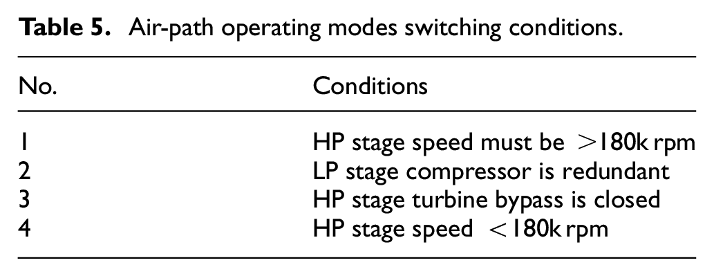
Figure 10 displays the input conditions of each operating mode and how the air-path is switched from one operating mode to another operating mode in the direction of arrows, having satisfied the condition number next to the arrow as listed in Table 5. Operating mode 1 is only relevant to the engine’s low speed and load operating conditions as long as the HPC is not choked and the LPC is redundant, that is, its pressure ratio is ≤1. Each of the air-path’s operating modes can only switch to one of the adjacent modes. Operating mode 2 is relevant to the engine’s higher speed and/or load conditions that creates sufficient exhaust flow to maintain the operation of two-stage in-series turbochargers. When the HP stage turbocharger in this mode has reached its limit due to further increase in engine’s exhaust flow, the air-path is switched to mode 3 where the HP stage shaft speed needs to be controlled below the compressor choke flow speed via adjustments to HPT bypass valve. This allows the LP turbocharger to gain speed before the air-path is switched to mode 4. However, depending on the turbochargers’ size and how they are matched with the engine, mode 3 may be found unnecessary in some cases, which simplifies the system. Operating mode 4 falls into the high speed and high load operating regions of the engine where the LP stage turbocharger’s natural response is adequate and only EGR position may be found necessary to be controlled.
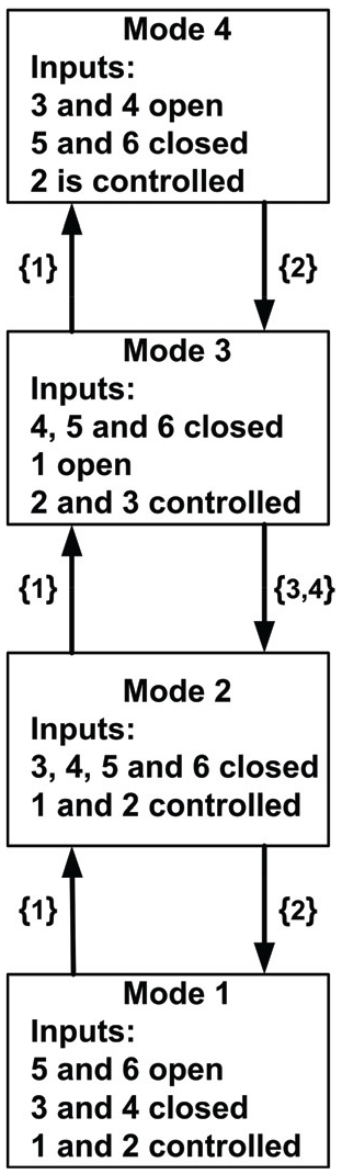
Two stage in-series turbocharged air-path operating mode management; the operating mode is changed in the direction of the arrows once the condition (Table 5) associated with each arrow is satisfied.
The resulting disturbance caused by closing the EGR flow during load transient events at low operating speeds on manifolds’ pressure (Figure 9(a)), has no significant destabilising effect on the engine’s open loop response. This is because the control input follows a predetermined map and the plant response is based on its natural dynamics. However, with closed loop linear control strategies, this action can saturate the control inputs. Closing the EGR, effectively corresponds to switching between two distinct air-path operating points, each belonging to a plant configuration with different dynamics. The switching in particular can lead to poor performance of the air-path if an integral term is used as part of the control strategy. Even in the absence of an integral term in feedback control, the input saturation may cause oscillations and limit cycles due to plant dynamics. 24 This is particularly true when the engine forces the air-path to cross the configuration boundaries mentioned earlier, where the controllers can become constrained. To avoid the resulting poor performance, the controller must be stabilised.
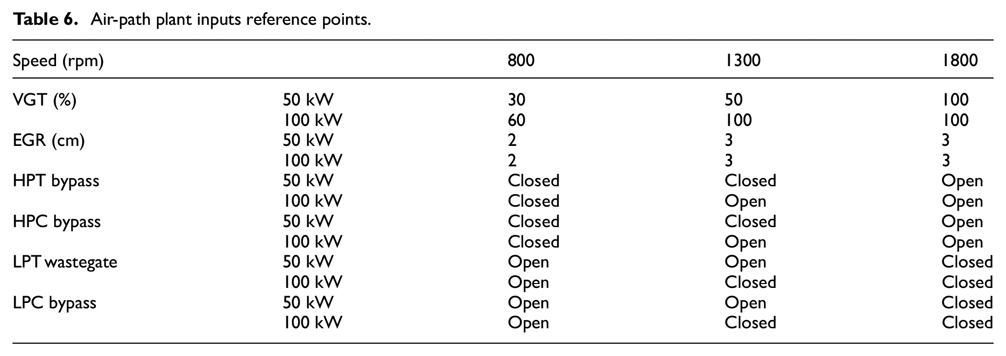
Figure 11(a) and (c) show pressure ratio, and Figure 11(b) and (d) show speed response of compressors to 50 kW step load when air-path is controlled to reference points of Table 6 at 800, 1300, 1800 rpm. The EGR valve is momentarily closed as step transient occurs at 800 and 1300 rpm. EGR is then tracked to reference points after the step. EGR valve remains open during the step transient at 1800 rpm as LP stage is well energised. Figure 12 shows the step transient NO x profile in the absence of EGR (Figure 12(a)) and when EGR is actuated to reference points (Figure 12(b)). The unfavourable conditions in Figure 4 are avoided. Compressors’ transient trajectories in Figure 13(a) and (b) show operation in higher efficiency regions.
Air-path plant inputs reference points.
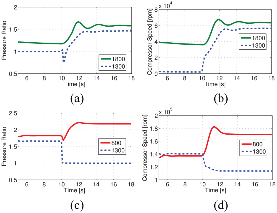
Compressors’ response to 50 kW step load when air-path is controlled at 800, 1300, 1800 rpm with EGR flow: (a) LPC pressure ratio, (b) LPC speed, (c) HPC pressure ratio, and (d) HPC speed.
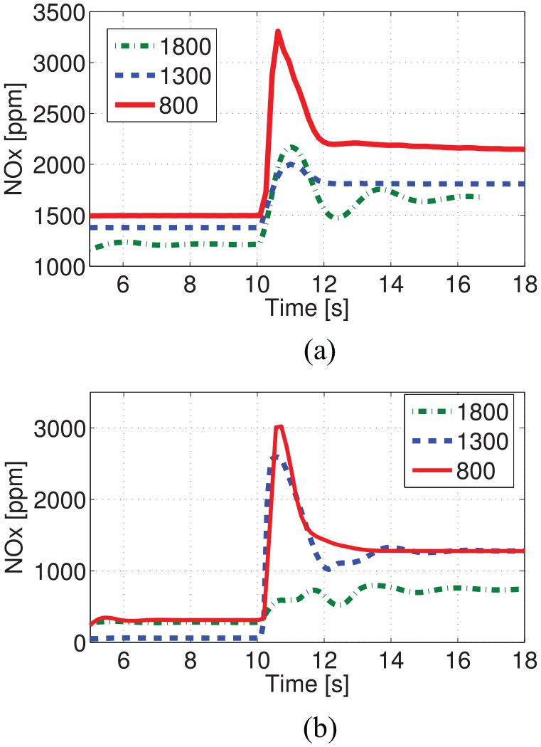
NO x transient profile at 800, 1300, 1800 rpm: (a) no EGR flow and (b) actuated EGR flow.
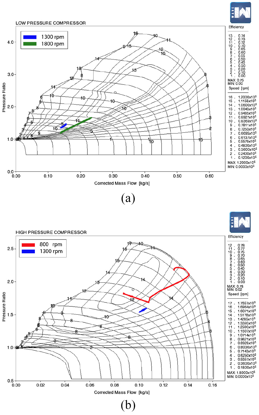
Step transient profile of controlled air-path at 800, 1300 and 1800 rpm on compressor maps: (a) LPC, (b) HPC. The air-path switches from HPC to LPC during transient at 1300 rpm.
Conclusion
In conclusion, the two-stage in-series turbocharged air-path appears to be a suitable candidate for down-speeding diesel engines. It can maintain the engine transient performance at lower operating speeds, resulting in better fuel economy. Controlling the two-stage in-series turbochargers’ turbines expansion ratio by manipulating the VGT position of the HP stage, allows more flexibility in the engine’s operating speed range. Closing the EGR path during low speed engine transient events, prevents prolonged excessive NO x production rate. However, given the complexity of the air-path system, an appropriate control strategy is critical to satisfactory performance. The air-path system control has been partitioned into four operating modes. Inputs and criteria for transitioning between modes have been identified. Controls for each operating mode can be designed using classical and modern control techniques.
Footnotes
Declaration of conflicting interests
The author(s) declared no potential conflicts of interest with respect to the research, authorship, and/or publication of this article.
Funding
The author(s) received no financial support for the research, authorship, and/or publication of this article.