
Abstract
Dilute combustion offers efficiency gains in boosted gasoline direct injection engines both through knock-limit extension and thermodynamic advantages (i.e. the effect of γ on cycle efficiency), but is limited by cyclic variability at high dilution levels. Past studies have shown that the cycle-to-cycle dynamics are a combination of deterministic and stochastic effects. The deterministic causes of cyclic variations, which arise from feedback due to exhaust gas recirculation, imply the possibility of using active control strategies for dilution limit extension. While internal exhaust gas recirculation will largely provide a next-cycle effect (short-timescale feedback), the feedback of external exhaust gas recirculation will have an effect after a delay of several cycles (long timescale). Therefore, control strategies aiming to improve engine stability at dilution limit may have to account for both short- and long-timescale feedback pathways. This study shows the results of a study examining the extent to which variations in exhaust gas recirculation composition are preserved along the exhaust gas recirculation flow path and thus the relative importance and information content of the long-timescale feedback pathway. To characterize the filtering or retention of cycle-resolved feedback information, high-speed (1–5 kHz) CO2 concentration measurements were performed simultaneously at three different locations along the low-pressure external exhaust gas recirculation loop of a four-cylinder General Motors gasoline direct injection engine using a multiplexed two-color diode laser absorption spectroscopy sensor system during steady-state and transient engine operation at various exhaust gas recirculation levels. It was determined that cycle-resolved feedback propagates through internal residual gases but is filtered out by the low-pressure exhaust gas recirculation flow system and do not reach the intake manifold. Intermediate variations driven by flow rate and compositional changes are also distinguished and identified.
Keywords
Introduction
Increasing the compression ratio is a well-established means of improving efficiency in spark-ignition engines.1,2 The compression ratio, however, is typically limited by the onset of engine-damaging phenomena such as end-gas knock at high loads. Compression ratio restrictions and/or spark timing retardation are thus employed to prevent knock, thus imposing fuel efficiency penalties. Furthermore, fuel enrichment is sometimes also required to protect engine components from thermal damage at high speeds and loads, further lowering the engine efficiency.
Some of these undesirable factors can be mitigated by diluting the in-cylinder charge with either fresh air or exhaust gases.3–7 Use of diluents (either fresh air or exhaust gases) not only reduces the mixture reactivity to prevent knocking, but the resultant lower exhaust temperatures also impose lower thermal stresses on the exhaust valves and turbocharger (if present). Efficiency and emissions benefits of dilution with exhaust gas recirculation (EGR) have been reported by a number of researchers.3,4 The knock-reducing effect of cooled EGR was demonstrated by Alger et al., 5 wherein each percent increase in EGR was shown to have similar knock-mitigation as a 0.5 point increase in fuel octane rating. In addition, stoichiometric engine operation can be achieved using dilution with EGR to maintain compatibility with three-way catalysts. Szybist et al. 6 more recently showed that the knock attenuation from EGR is substantially reduced for highly boosted operation, though significant efficiency advantages remain at lower specific loads and for less aggressively boosted engines. Fresh air can also be used as a dilution medium to obtain most of the benefits of dilution with cooled EGR. While dilution with fresh air (or lean operation) does provide better thermodynamic efficiency (through favorable changes in γ), 1 lean operation also requires the use of complex after-treatment devices such as lean NOx traps and is not as effective as cooled EGR in mitigating knock. 7
The use of charge dilution in gasoline spark ignited (SI) engines is limited by the onset of combustion instabilities. Dilution reduces both the flame kernel growth rate 8 as well as the flame speed3,9 and can lead to poor combustion through either partial burns or misfires depending on which factor dominates at a given operating condition. Beyond a certain dilution level, the frequency of these adverse combustion events increases dramatically, leading to reduced engine performance, increased noise, and increased vibration, all of which are unacceptable in modern engines.
Numerous efforts have been made by researchers to understand and characterize these combustion instabilities. Daw et al. 9 modeled cyclic variability in a port-fuel-injected lean gasoline engine as being driven by a nonlinear dependence of combustion efficiency on composition. Their model tracks residual gas composition with unburned fuel from a given cycle being fed forward to the following cycle; they also imposed a stochastic noise onto the initial conditions to simulate random effects such as in-cylinder turbulence and mixture inhomogeneity. This study demonstrated that modeling the cyclic variability as a deterministic feed-forward function of the in-cylinder residual gas composition effectively captures the dynamics of cycle-to-cycle variations observed in real engine data. Other experimental data have also confirmed the findings of this model that the nonlinear dependence of the flame kernel growth as well as the flame speed on the charge composition are the primary factors that determine combustion efficiency.10–12
Kaul et al. 13 used symbol sequence analysis to explore the cyclic variability of dilute spark-ignition (SI) combustion using an external, low-pressure, cooled EGR loop on a modern turbocharged gasoline direct injection (GDI) engine. This same engine is also used in this study. Symbol sequence analysis involves discretization of the data (typically cycle-cumulative heat release data) into bins, each represented by a symbol or “letter” and evaluation of the reoccurring sequences or “words” of a given length comprised of those symbols, with the number of discrete bins and the word length being chosen as appropriate to elucidate recurring patterns in the data. The study conducted by Kaul et al. 13 also showed a considerable amount of determinism in the heat release data, which was further shown to have potential to be used as a basis for devising control strategies to improve engine stability. The presence of deterministic content in cyclic variations has also been demonstrated by several other studies conducted on dilute, propagating flame combustion systems. 14 A key implication of the presence of deterministic structure to cyclic variations is that deterministic systems can be controlled: if the dynamics of the system are sufficiently well-understood, perturbations to inputs for the upcoming engine cycle (e.g. fuel injection, spark timing) can be used to control and stabilize the system based on knowledge of past cycles, thus reducing cyclic variability.
During dilution with fresh air, internal residual composition is the only source for deterministic feed-forward communication, as the information (in this case, unburnt fuel) can be fed forward to the next cycles only through internal residual gas composition. However, for dilution with EGR, information can be fed forward through either the internal residual or the external recirculation path. Therefore, efforts to identify deterministic effects during dilution with EGR should account for prior-cycle effects (internal recirculation) as well as the effect of a sequence of cycles further in the past. The situation becomes even more complex in multi-cylinder engines due to the cross-communication between the cylinders, that is, a cylinder may get the information (external EGR) generated by another cylinder. Kaul et al. 15 explored the effect of EGR path length on the dynamics of cyclic variability using multiple EGR loop lengths. The study was performed at very high EGR levels to accentuate the effect of external recirculation loop on the measured deterministic content frequency, and it was observed that at these very high EGR levels, the recirculation loop length did play a crucial role in shaping the deterministic content. In addition, oscillations in the intake manifold hydrocarbon concentration measured using a Cambustion HFC400 fast flame ionization detector (FID) correlated with the oscillations in measured heat release, therefore confirming the effect of feed-forward content in cyclic variability.
This study aims to further characterize the lifetime of the cyclic variations as they move along the external recirculation loop from the exhaust port to the intake port. In the external recirculation loop, the exhaust gases travel through the turbine, the EGR cooler, the EGR valve, the compressor, the charge air cooler (CAC), and finally through the throttle valve to reach the intake manifold. All these devices could act as low-pass filters and work to average out the cyclic variability in the external EGR stream. If the external EGR stream introduces cyclic variability to the intake manifold gas composition, then any effort to construct engine-cycle-resolved control strategies that would use prior-cycle information and knowledge of system dynamics to actively stabilize the system and reduce cyclic variability must also account for this effect. In addition, the exact source of the variability must be identified to characterize the time constant of the feed-forward function in the external EGR loop.
Experimental setup
Measurements for this study were performed on a 2.0L GM LNF (General Motors Engine Code) engine that was modified by Bosch with a higher compression ratio in a previous US Department of Energy (DOE) E85 (fuel mixture with 85% Ethanol and 15% Gasoline) optimization study and outfitted with a low-pressure cooled EGR loop at Oak Ridge National Laboratory (ORNL). This engine has been used in several previous studies at ORNL.13,15 The specifications of this turbocharged GDI engine are listed in Table 1. A LabVIEW-based system was used to control the EGR flow rate using a VW TDI (Volkswagen Diesel Engine Designation) EGR valve, and back pressure for the low-pressure EGR loop was provided by the original equipment three-way catalyst in the exhaust stack. Engine control was provided by a National Instruments Powertrain Controls Engine Control System (ECS) that is capable of next-cycle control action. Mean intake and exhaust gas concentrations were monitored using a standard suite of emissions benches, and engine stoichiometry was monitored using a Bosch LSU 4.9 wideband oxygen sensor (Bosch Wideband Sensor Series). Water-cooled heat exchangers for engine coolant, engine oil, charge air, and EGR were independently controlled using external proportional–integral–derivative (PID) controllers. Haltermann United States Environmental Protection Agency (EPA) Tier II EEE certification gasoline, with properties as shown in Table 2, was used for all experiments.
Engine specifications.
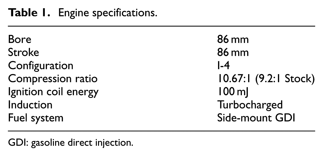
GDI: gasoline direct injection.
Fuel properties.
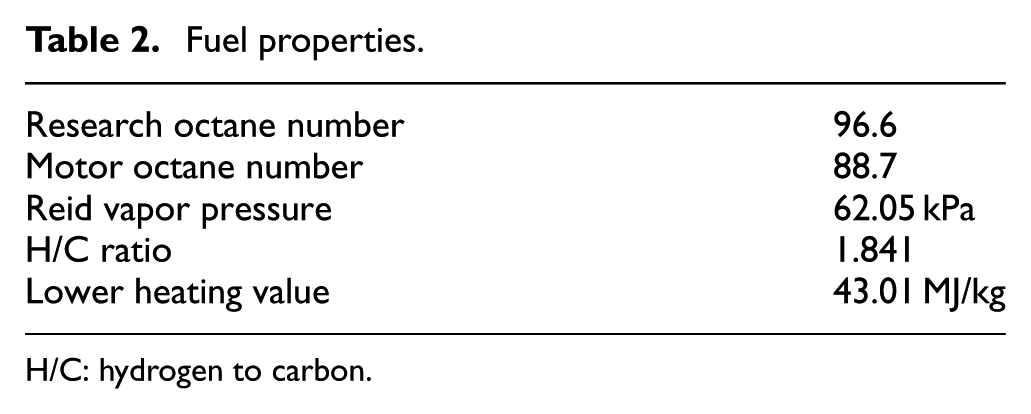
H/C: hydrogen to carbon.
As shown in Figure 1, the EGR system was instrumented at three locations (the EGR cooler outlet, compressor outlet, and the intake manifold) to simultaneously characterize temporal variations in the EGR stream using high-speed gas concentration measurements performed with a diode-laser-absorption sensor. 16 This sensor has the capability to perform gas temperature, pressure, and H2O and CO2 concentration measurements simultaneously at four different locations with 5 kHz measurement bandwidth. This sensor and its prior iterations have previously been used to perform high-speed measurements at various locations on internal combustion engines such as intake manifold, 17 turbocharger inlet, 18 and intake ports. 19 Even though all gas properties (temperature, pressure, (H2O), and (CO2)) were measured using this sensor, only the (CO2) values are reported here. This is because the temperature and (H2O) values will be reduced by both the EGR cooler and the CAC, possibly removing any variations in those properties.
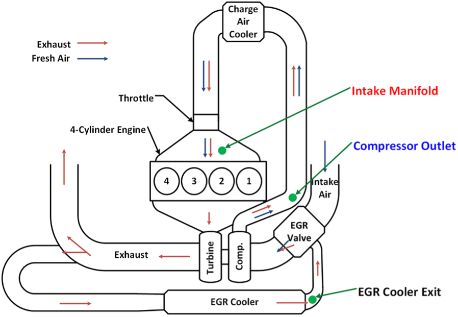
Illustration of the low-pressure-loop external EGR system as well as the three measurement locations: EGR cooler exit, compressor outlet, and intake manifold.
Prior publications have described the high-speed EGR probe system in detail, 16 and therefore, only a brief overview of the system is given here. All the subcomponents of the EGR probe system are illustrated in Figure 2. This system consists of two subsystems: a H2O absorption system for gas temperature, pressure, and H2O concentration measurements and a CO2 absorption system that provides the CO2 concentration information using the high-speed gas temperature and pressure measurements from the H2O system. Both subsystems use distributed-feedback diode lasers, with wavelengths of 1.39 µm for H2O spectroscopy and 2.7 µm for CO2 spectroscopy, for the absorption measurements. Engine measurements were performed using compact probes 16 (9.525 mm (3/8″) outer diameter stainless steel tube) that were installed on the engine using ¼ National Pipe Thread (NPT) Swagelok fittings. Using four of these probes, this high-speed EGR probe system can perform gas property measurements at four different locations simultaneously. Figure 3(a) illustrates a sample application of a probe for gas property measurements in a 2″ (50.8 mm) internal diameter pipe using a Swagelok connector. The two measurement ducts of the probe, where laser light interacts with the measurement medium, are also marked out in Figure 3(a), while details of these measurement ducts are illustrated in Figure 3(b) with a sectioned view of the probe tip. The window and gasket provide sealing for the measurement gas, and the combination of the lens and mirror direct the light exiting the window back into the light collection fibers inside the probe. Optical fibers and hollow waveguides were used to direct the light between the instrument and the probes; the length of these was chosen as 2 m to get an appropriate stand-off distance between the engine and the instrument. At the gas conditions expected in the intake gas stream, the sensor has previously been shown to have around 10% uncertainty in the absolute values of the measured gas properties. 16
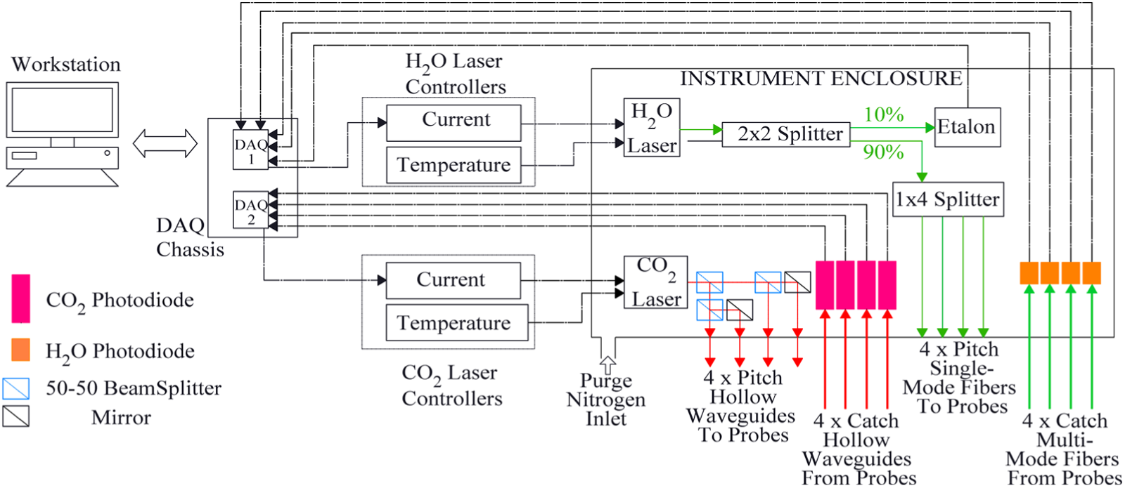
Schematic of the two-color diode, laser-absorption-based, high-speed EGR probe system. 16
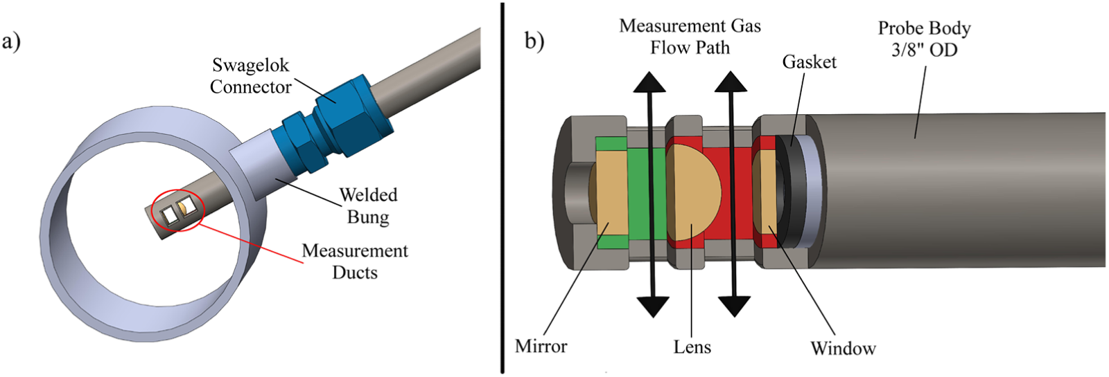
(a) Illustration of a sample application of a probe for measurements in a 2″ internal diameter pipe. The two measurement ducts are marked out. (b) Details of the two measurement ducts on the probe tip. The window and gasket provide sealing for the measurement gas, and the combination of the lens and mirror directs the light exiting the window back into the light collection fibers inside the probe.
Results
Three probes were utilized to simultaneously measure gas properties at the EGR cooler exit, the turbocharger compressor exit, and the intake manifold. Gas concentration measurements were performed at these three locations for three different engine test conditions: (1) steady-state operation at various EGR levels, (2) EGR valve cycling, and (3) Cylinder 1 fueling cycling. For all three cases, the engine was run at 2000 r/min and the fueling was adjusted to achieve 4 bar brake mean effective pressure (BMEP) at zero dilution. Thereafter, the fueling was fixed for the entire study, and the desired EGR level was achieved by adjusting the intake air throttle and/or the EGR valve; additionally, care was given to maintain stoichiometric operation.
Steady operation at various EGR levels
In this case, measurements were performed during steady-state engine operation at various medium and high EGR levels. The tested medium (17%) EGR level represents the edge of stability with ∼10% coefficient of variation (COV), while the high (30% and 40%) EGR levels were used to identify the EGR level where instabilities were observed to reach the intake manifold. These levels are beyond the practical dilution limit that would be used in production for this engine at this speed/load condition but were chosen to clearly elucidate the dynamics of composition feedback through the EGR flow path. The high EGR cases also provided qualitative comparison with the observations of previous studies.
Figure 4 shows the CO2 concentration measured at the three locations during operation with 17% EGR. At this EGR level, some adverse combustion cycles (either incomplete combustion or misfires) were observed during engine operation, which implies that implementation of next-cycle control strategies to mitigate cyclic variability could be beneficial at this operating condition. These adverse combustion cycles are identifiable as cycles exhibiting reduced CO2 concentration measured with the probes; two such instances are illustrated in the time series data in Figure 4. The EGR cooler exit is the measurement location physically closest to the exhaust port, and therefore, engine-combustion-driven concentration changes should manifest earlier at this location as compared to the other two locations in the EGR flow loop; however, Figure 4 depicts that the gas concentration at the compressor outlet was observed to change around 0.25 s before any change was observed at the EGR cooler exit. In addition, gas concentration changes at the compressor outlet were temporally sharp, while more temporally diffused measurements were observed at the EGR cooler exit. This behavior indicates that the gas concentration changes observed at the compressor outlet are not driven by the same gas-transport phenomena that drive changes in the gas concentration at the EGR cooler exit. It is hypothesized that this phenomenon observed at the compressor exit is due to changes in EGR flow rather than EGR composition: the adverse combustion cycles create either a loss of suction at the compressor inlet or a loss of back-pressure in the exhaust stream, both of which would result in lower flow through the EGR valve. This phenomenon is consistently observed at compressor exit after each adverse combustion cycle. Since an exhaust pulse reaches the turbocharger before it reaches the EGR cooler exit, changes in composition due to turbocharger performance and EGR flow rate would be observed at the compressor exit prior to changes in composition from flow transport reaching the EGR cooler exit.
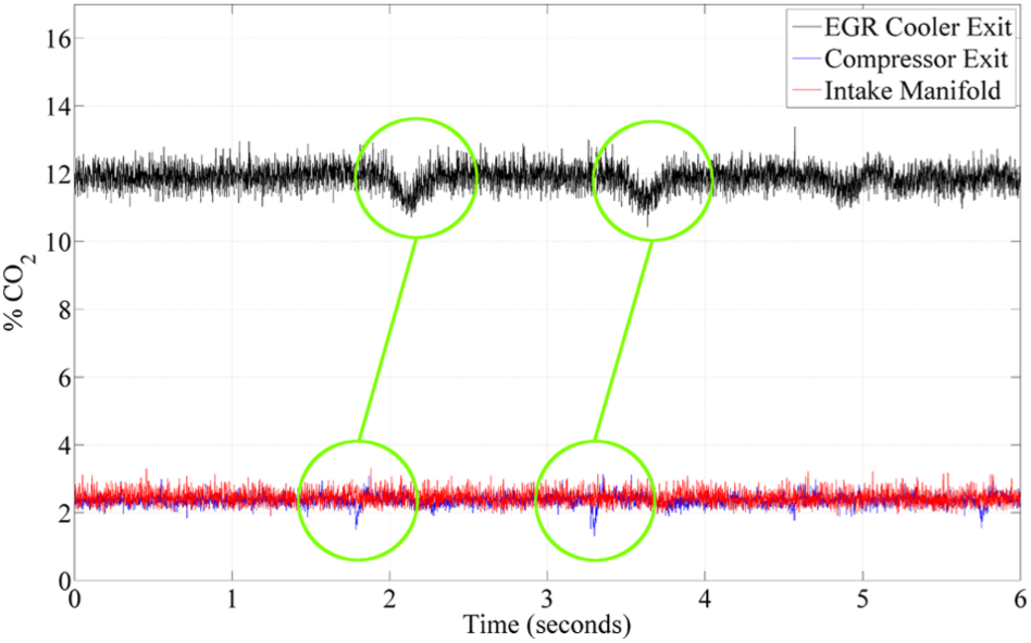
Temporal changes in the CO2 concentration measured in the external EGR loop measured at the EGR cooler exit, compressor exit, as well as the intake manifold at 17% EGR. A COV of 12% was observed at this condition. Gas concentration at the compressor outlet was observed to change around 0.25 s before any change was observed at the EGR cooler exit. All on-engine actuators are held at fixed positions, and therefore, the observed fluctuations are a direct result of combustion-related phenomena.
If the transport-driven changes in composition observed at the EGR cooler propagated independently to the compressor outlet, one would expect to observe two sets of changes at the compressor outlet: one due to the turbocharger/flow rate effect and the other due to a different composition of gases coming through the EGR cooler. In fact, only a single set of changes was observed at the compressor outlet. Therefore, it can be concluded that the cycle averaging (or low-pass filtering) effect of the EGR valve and the compressor is strong enough to sufficiently dampen any temporal structure coming through the EGR stream and that the EGR valve would become the effective source point of the instabilities as opposed to the exhaust valve. Furthermore, at this EGR level, even though instabilities were observed at the compressor outlet, the averaging effect of the charger air cooler as well as the throttle valve ensured that there were no cycle-resolved instabilities in the gas entering the intake manifold; therefore, the external EGR loop could be ruled out as an effective source of feed-forward information for next-cycle control implementation at medium levels of EGR.
The CO2 concentration measured at the three measurement locations during high levels of EGR operation is shown in Figure 5 (30% EGR) and Figure 6 (40% EGR). At these high EGR levels, combustion was highly unstable, as indicated by very high COV values. At 30% EGR, an increased frequency of temporal changes in concentration was observed at the EGR cooler exit and the compressor outlet; however, gas concentration in the intake manifold still did not show any evidence of these variations. While at very high levels of EGR (>40%), changes in CO2 concentration were observed in the intake manifold, these variations were temporally very slow compared to an engine cycle. At these high EGR levels, a slower oscillation was observed in the external EGR loop in addition to the previously observed fast variations. These slower oscillations resulted from synchronous periodic oscillations between complete combustion and misfires in all four cylinders due to the very high dilution levels. This observation is consistent with the observations of a previous study conducted by Kaul et al. 15 where such oscillations were observed during around 50% EGR operation. As shown in Figure 6(b), the individual cylinder and cycle effects (fast variations), however, still do not propagate to the intake manifold.
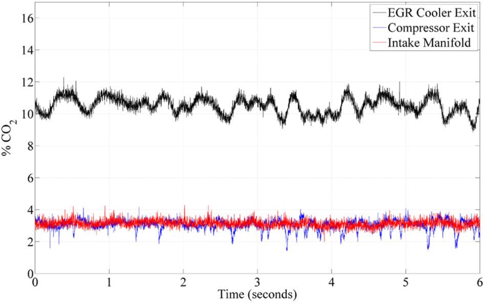
Temporal changes in the CO2 concentration measured in the external EGR loop measured at the EGR cooler exit, compressor exit, as well as the intake manifold at 30% EGR. A COV of 34% was observed at this condition. All on-engine actuators are held at fixed positions, and therefore, the observed fluctuations are a direct result of combustion-related phenomena.
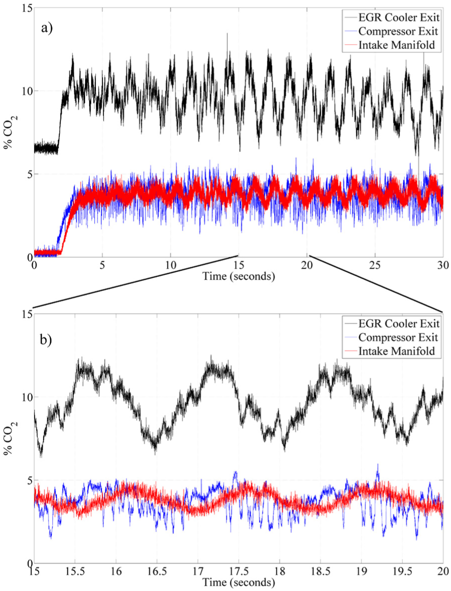
(a) Instabilities in the external EGR loop CO2 concentration measured at the EGR cooler exit, compressor exit, and intake manifold during engine operation at 40% EGR. The engine operation was highly unstable at this condition and showed slow oscillations, wherein, most of the cylinders would fire or misfire synchronously. (b) Enlarged view of 5 seconds of operation. Here, it can be seen that while slow oscillations propagated through the external EGR loop all the way to the intake manifold, the instabilities associated with individual engine cycles were not observed in the intake manifold. All on-engine actuators are held at fixed positions, and therefore, the observed fluctuations are a direct result of combustion-related phenomena.
EGR valve cycling
Measurements were performed at 30% EGR, while the EGR valve was cycled on and off to capture the lag between the compressor outlet and the intake manifold. Figure 7 shows the CO2 concentrations measured at the three locations as the EGR valve was cycled off and on three times from 7 to 27 s. When “off,” the EGR valve is fully closed, and when “on,” the valve opens to a set position each time. The changes in concentration at the intake manifold location were observed to lag the changes observed at the compressor outlet location by around 0.6 s due to the transport delay of the bulk gas between these two locations, and this delay was found to be consistent with the prior flow-path observations for this engine. In addition, in agreement with the measurements at steady-state conditions, combustion-cycle-related variations are also observed at EGR cooler exit and the compressor outlet when the EGR valve is open.
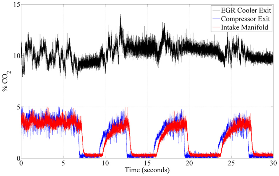
CO2 concentration measurements at the three locations in the external EGR loop, while the EGR valve was cycled off and on three times from 7 to 27 s. When “off,” the EGR valve is fully closed, and when “on,” the valve opens to a set position each time.
Cylinder fueling cycling
To understand the propagation of intentionally introduced variations in the EGR loop gas concentration, the engine fueling rate was cycled. This approach toggled fueling for cylinder 1 by cycling the fuel injection command between on-and-off, while the fueling for other three cylinders was kept constant to create a known source of misfire. This ensured control over both the source as well as the onset of the variations and allowed for accurate tracking of variations from the source, that is, the exhaust ports of cylinder 1, all the way to the intake manifold. In addition, this ensured that the timescale of the variations was on the order of an individual engine cycle. Figure 8(a) shows the CO2 concentration measured at the three locations for 20% EGR as the cylinder 1 fueling is turned off, and Figure 8(b) shows the CO2 concentration measured at the three locations for 20% EGR as the cylinder 1 fueling is turned on. The cylinder pressure trace for cylinder 1 is also shown in Figure 8. Two types of variations are observed in this case also: fast variations that are of the order of an individual cylinder cycle and a slow variation that represents a 25% drop in the exhaust CO2 concentration due to the absence of combustion in cylinder 1. The fast variations arrive at the compressor exit around 1.5 cycles after the fueling is turned off relative to cylinder 1. This 1.5-cycle delay is consistent with the cycle-based time required for the gases to flow from the exhaust port to the turbocharger plus from the EGR valve to the sensor. Furthermore, these fast variations were not observed at the EGR cooler exit, confirming that these measured variations represent a change in the flow rate through the EGR valve (due to either turbocharger or exhaust back pressure dynamics) as opposed to a change in the gas composition upstream of the EGR valve. Finally, as illustrated in the steady-state measurements, this fast variation phenomenon is closely tied to adverse combustion events (misfires). The slow variation, however, arrives at the EGR cooler exit ∼0.3 s (five engine cycles) before it is observed at the compressor exit, as this variation represents the change in exhaust composition due to only three firing cylinders and must propagate through the EGR cooler before reaching the compressor outlet and intake manifold. Consistent with the observations of other cases, only the slow variation can be observed at the intake manifold. The change can be seen as a slow drop in the intake CO2 concentration from 3 to 3.5 s in Figure 8(a) as well as a slow rise in the intake CO2 concentration from 7.5 to 8 s in Figure 8(b). In addition, this slow bulk change in the gas concentration also exhibits the 0.6 s delay between measurement locations 2 and 3.
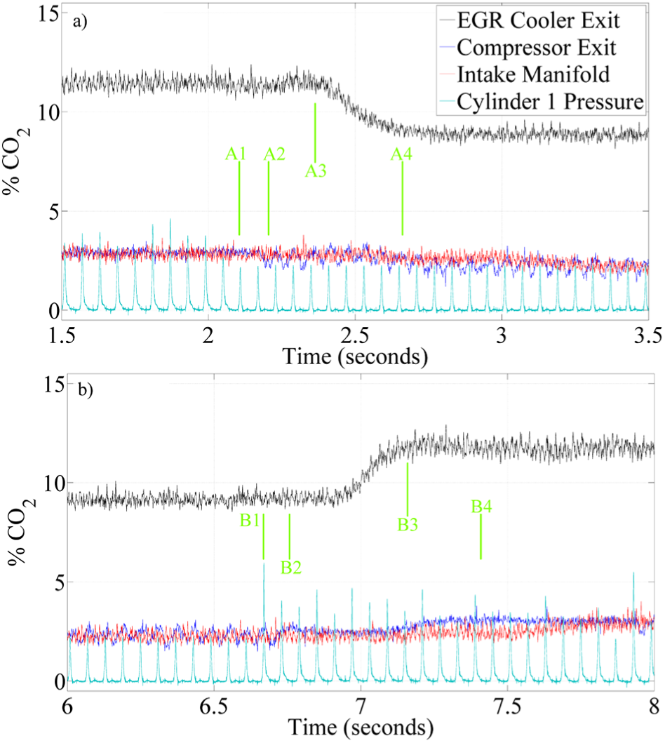
Instabilities in the external EGR loop created by turning off the fueling to cylinder 1: (a) fueling is turned off (time is marked as A1) and (b) fueling is turned back on (time is marked as B1). Fast oscillations were observed at the compressor exit 1.5 engine cycles after fueling is toggled (times A2 and B2); however, these variations are not observed at either the EGR cooler exit or the intake manifold. A slow shift was observed at the EGR cooler exit at times A3 and B3, and the corresponding shift arrives ~0.3 s later at the compressor exit (times A4 and B4).
Summary
In this study, the gas property variations introduced into the intake manifold through the external EGR loop were characterized at various external EGR levels to study the life-span of an instability across the low-pressure-loop EGR system from the EGR cooler to the intake manifold. The main source of variations in the intake manifold was observed to be the slow changes in the exhaust concentration at very high EGR levels. However, the individual cylinder-cycle-related variations were observed to have been damped out by the time the gas reached the intake manifold. These variations were observed to be originating from turbocharger dynamics as opposed to being transferred through the EGR cooler; therefore, the source of such variations should be taken as flow dynamics at the EGR valve instead of composition changes at the exhaust port.
This implies that active control systems seeking to make use of nonlinear system dynamics to stabilize high-EGR operation should focus on the impact of internal residual composition rather than the longer-time-scale feedback of an external low-pressure EGR loop and that in order to benefit from active control at the dilute limit, at least a portion of the dilution would need to be in the form of internal residual gases rather than externally recirculated exhaust gases. The temporal averaging of the external EGR loop eliminates the deterministic coupling between individual cycles that would be relied upon for such control strategies and pushes the cyclic variability into a stochastic regime. This study does not address the impact of a high-pressure EGR loop: with fewer devices in the flow path (i.e. bypassing the turbocharger, etc.), it is plausible that some feed-forward information could be retained; the configuration is sufficiently different from that in this study that a conclusion cannot be drawn from this work.
Footnotes
Acknowledgements
The authors would also like to thank Robert Bosch, LLC for providing the engine used in this study.
Declaration of conflicting interests
The author(s) declared no potential conflicts of interest with respect to the research, authorship, and/or publication of this article.
Funding
The author(s) disclosed receipt of the following financial support for the research, authorship, and/or publication of this article: This work was funded by the US Department of Energy’s Vehicle Technologies Office under the guidance of the Advanced Combustion Engine Research and Development program managed by Gurpreet Singh and Michael Weismiller.