
Abstract
Variable geometry turbine is a technology that has been proven on diesel engines. However, despite the potential to further improve gasoline engines’ fuel economy and transient response using variable geometry turbine, controlling the variable geometry turbine during transients is challenging due to its highly non-linear behaviours especially on gasoline applications. After comparing three potential turbocharger transient control strategies, the one that predicts the turbine performances for a range of possible variable geometry turbine settings in advance was developed and validated using a high-fidelity engine model. The proposed control strategy is able to capture the complex transient behaviours and achieve the optimum variable geometry turbine trajectories. This improved the turbocharger response time by more than 14% compared with a conventional proportional–integral–derivative controller, which cannot achieve target turbocharge speed in all cases. Furthermore, the calibration effort required can be significantly reduced, offering significant benefits for powertrain developers. It is expected that the structure of this transient control strategy can also be applied to complex air-path systems.
Keywords
Introduction
Reduction in the fuel consumption of internal combustion engines can be achieved by downsizing. The efficiency is improved by moving the engine’s fuel-efficient zones closer to normal road driving conditions and shifting to a more efficient operating region through reducing engine displacement while maintaining the full-load capacity via air charging.1,2 Reduction in engine friction and throttling losses can be achieved. Furthermore, the weight of the engine and hence that of the vehicle can be lowered3,4 and manufacturing costs can be reduced by turbocharging the same base engine to achieve a family of engine powers derived from a common base engine architecture. 5
Turbocharging is one of the primary approaches to achieve downsizing for fuel economy. The variable geometry turbine (VGT) turbocharger is an advanced technology that has been widely used on diesel engines. The wider operating range with high efficiency enables significant reduction in fuel consumption and emissions of diesel engines. The air mass flow variation in a gasoline engine is significantly higher than that of a diesel engine, due to the range of engine speeds and manifold pressure conditions between idle and full-load operation, 6 highlighting the necessity of varying the characteristics of the boosting system on gasoline engines. 3 However, VGT technology that has the capability has only been used on few production gasoline engines. The key challenges of using VGT on gasoline engines include the harsh exhaust environment due to higher exhaust gas temperature than diesel engines, which can be dealt with using more costly material. In addition, the control of VGT was also challenging because of the complex and non-linear behaviours of VGT. Also, adoption of water-cooled/integrated exhaust manifolds and cooled exhaust gas recirculation (EGR) may enable reduction in gasoline exhaust gas temperature and thus the turbine inlet temperature.
This article attempts to address the challenges in controlling a VGT turbocharger on a modern gasoline direct injection engine. The experiments and simulations were carried out. Steady-state test was performed to calibrate a high-fidelity engine model. The model was then validated against transient engine test data. Three possible transient control strategies were investigated. The proposed strategy was validated on three VGT turbine maps at two engine speeds using the validated engine model.
Methodology
Experimental approach
The experiments were performed on a 2.0-L gasoline engine equipped with turbocharger system, direct injection, and continuously variable valve timing (inlet and exhaust). The maximum torque and rated power from the production calibration were 300 N m and 150 kW, respectively.
In transient tip-in tests, the pedal position was set in closed-loop control to maintain target engine load before tip-in, 2 bar brake mean effective pressure (BMEP). The pedal position was set to 100% at tip-in. At the same time, the VGT position control was set to transient mode in which the pre-defined trajectory was used.
In order to reach a repeatable thermal condition, the engine was warmed-up following a fixed procedure at the start of each test campaign. In addition, 5 min was allowed for stabilisation before each tip-in. The duration of each tip-in test was designed to be as short as possible to achieve a stable and repeatable engine thermal condition between tests. The target engine load was lowered to settling point within 10 s after tip-in. Both the low-frequency data and high-frequency data were recorded for fixed periods of time covering 5 s before tip-in and 10 s after tip-in.
The original fixed geometry turbine (FGT) turbocharger was replaced with a VGT turbocharger. In order to control the VGT actuator on the prototype hardware, a dSpace Micro Auto Box was used. The actuator was cooled using the engine coolant, and the temperature was monitored in dSpace. In transient tests, the user-defined VGT trajectory can be automatically triggered using the pedal position voltage signal from the test facility host system.
The data were logged in three systems: Dewetron (high frequency and combustion analysis), ATI Vision (calibration tool), and CP Cadet (host system). The resolution of the high-frequency data recorded in Dewetron was 0.5° crank angle, which was equivalent to a maximum sampling frequency of 78 kHz at 6500 r/min. These data were used for the calibration of the engine combustion system and the turbocharging system. The key sensors used in the experiments are listed in Table 1.
Key measurement channels.
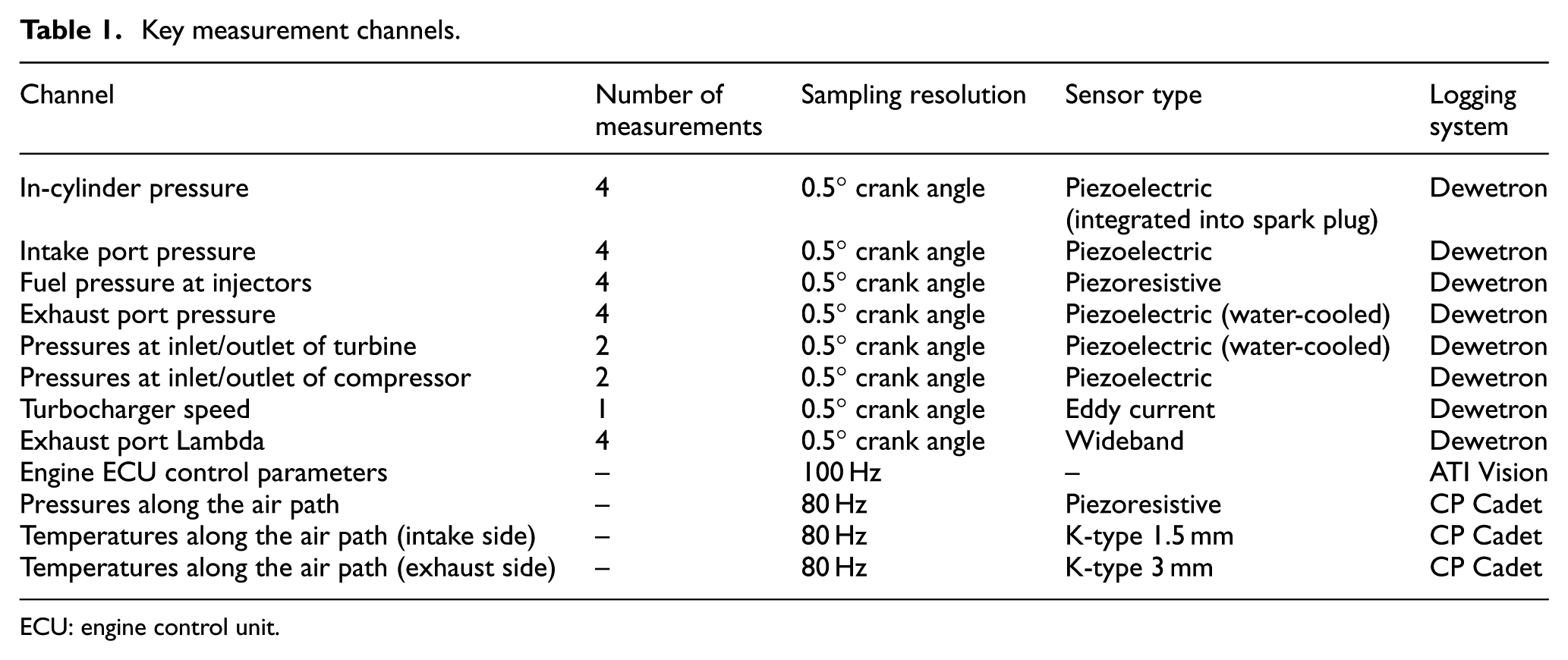
ECU: engine control unit.
Model validation
GT-Power, one of the typical one-dimensional (1D) engine simulation codes, is used in this investigation because of the capability of assessing the overall system performance of the engine with excellent accuracy.
Since the engine hardware was available and the engine block geometries were not to be changed in this project, combustion model with extensive predictability was not required. The engine model was calibrated using experimental data performed in the engine speed range of 1000–5800 r/min and BMEP range of 2 bar to full load. The combustion heat release profiles were calculated and used to build a semi-predictive combustion model. The profiles were looked-up and interpolated based on engine speed and instantaneous mass air flow into the cylinders. This is a typical approach to provide both accuracy and fast computational time, provided that the model operates within the calibrated range.
The engine model was calibrated and validated by following the order: engine cylinder, exhaust manifold, compressor, turbine, and complete engine. Table 2 shows the result of the steady-state validation of the complete engine system model at 2000 r/min 229 N m. The discrepancy was within ±3%. This formed a good foundation to transient model calibration, since the aim was to improve the accuracy by incorporating more physics instead of correlation coefficients.
Steady-state model validation.
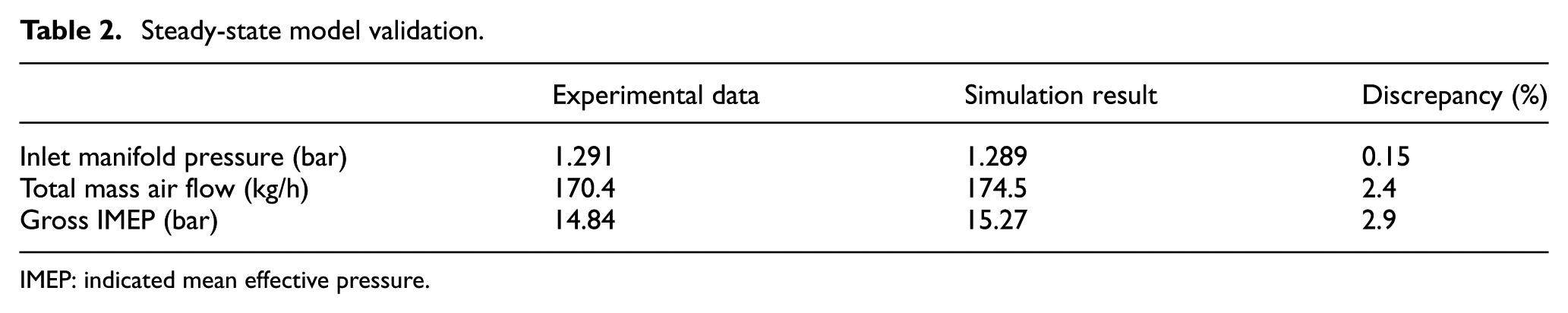
IMEP: indicated mean effective pressure.
Following the same philosophy, transient model was calibrated and validated from cylinder level to full engine level. Figures 1–3 show the result of the final validation of the complete engine system during transient at 2000 r/min. In general, the discrepancy between the experimental data and simulation results was within ±7.5% for the transient simulations.
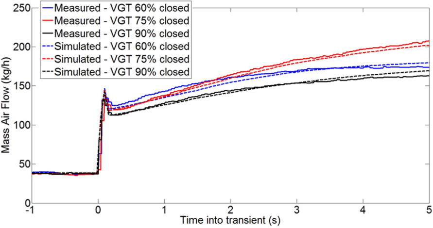
Measured and simulated mass air flow during transient.
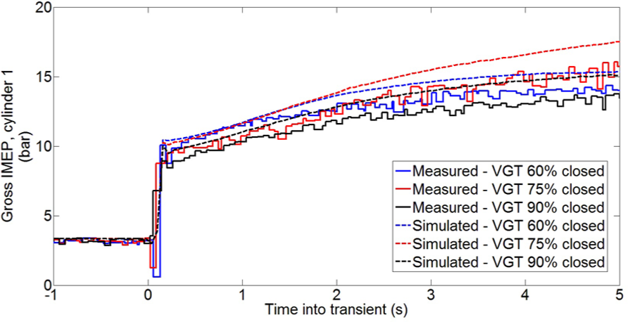
Measured and simulated gross IMEP at cylinder 1 during transient.
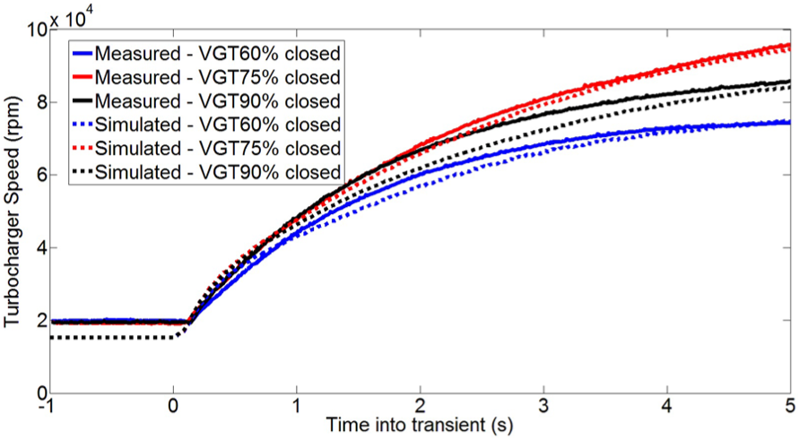
Measured and simulated turbocharger speed during transient.
Challenges in controlling the VGT during transient
It has been highlighted that the complex and non-linear response of the VGT turbocharger causes challenges and additional calibration efforts in controlling gasoline engines with VGT turbochargers efficiently. 7 This is because of the interaction between the turbocharger system and the combustion system. On conventional FGT turbochargers with waste-gate, the waste-gate is always fully closed until the target boost pressure is reached during transient accelerations. However, on VGT turbochargers, fully closing the vanes may result in excessively high back pressure at exhaust ports and low volumetric efficiency of the engine, which in turn results in trapped residual gas fraction, a potential knock instigator. Despite the high turbine expansion ratio, the engine exhaust gas mass flow and turbine efficiency may be largely reduced causing insufficient turbine power to drive the compressor. Thus, the high flexibilities need to be efficiently managed to exploit the full potential of VGT.
This is more critical on gasoline engines than on diesel engines. The scavenging process of gasoline engines usually employs larger valve overlap to reduce the residual gas fraction in the cylinder, especially at low speed high load. Therefore, the high back pressure at exhaust port is likely to cause back flow of exhaust gas which increases residual gas fraction and abnormal combustion behaviours on gasoline engines. However, the use of high-pressure EGR on diesel engines requires higher exhaust manifold pressure (to act as a pressure driver).
Because of the non-linearity of the VGT turbocharger, overshoot in VGT position feedback control may result in both slow turbocharger acceleration and slow torque response. In addition, the controller output may converge to unwanted values, for example, fully closed. Thus, to enable the robust and optimal use of the VGT turbocharger on gasoline engines, an advanced control strategy is necessary.
In order to demonstrate the challenges in the simulation and to compare with the experimental results from previous investigations, the transient simulations were performed from 2 bar BMEP to full load at 1500 r/min fixed engine speed. The fixed speed tip-in test is a typical method to assess engine transient response in development process, despite the difference between fixed speed transient and vehicle acceleration. Therefore, turbocharger acceleration is key to fast engine response, since the engine torque generation of the turbocharged engines relies on the boost pressure build-up, hence the turbocharger speed.
The transient turbocharger acceleration during 4.5 s after tip-in, which is a typical turbocharger response time, was optimised by performing design of experiments (DOE) of VGT position at each 1.5-s period. The 1.5-s time step was chosen to reduce the computation effort, and the DOE approach was selected because the transient behaviour at any time step is a result of the behaviours at all the previous time steps. The VGT trajectory that provided the fastest turbocharger acceleration is shown in Figure 4. The VGT position was set to 30% closed to match the exhaust manifold pressure level as that measured on FGT turbocharger at the same operating point. It was found that the optimum VGT position for the fastest turbocharger speed rise at each stage varied between stages. This is particularly challenging for controlling the VGT efficiently during transients.
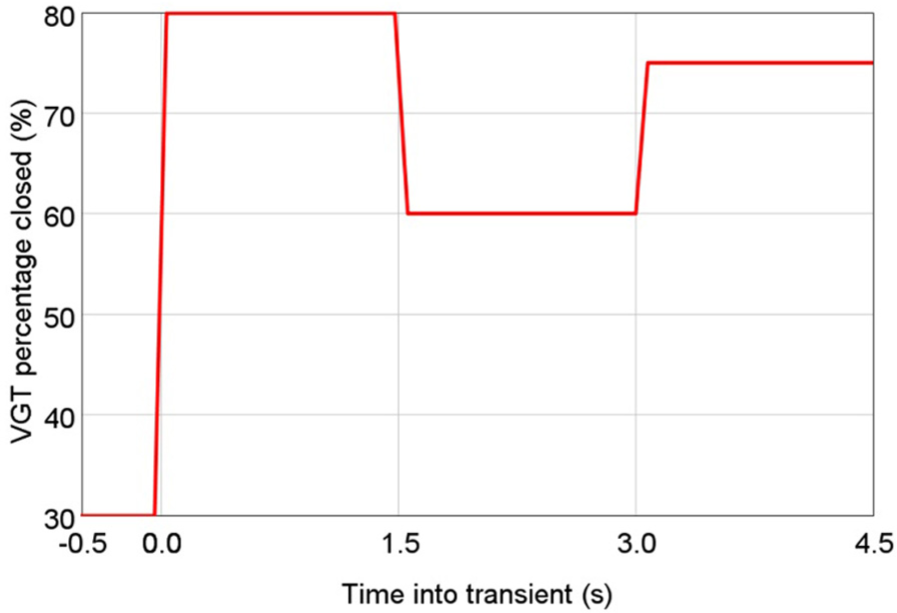
Simulated optimum VGT trajectory at 1500 r/min.
Selection of control strategy
Having reviewed the challenges, an advanced control strategy is required for the engine control unit (ECU) on internal combustion engines of passenger cars. The ECU control strategy is generally formed of sub-functions with different levels of complexity. The selection of the structure of each sub-function depends on factors that include the accuracy required, the characteristics and complexity of the target sub-system, the computational time, and the effort required to calibrate the model in the control strategy.
For example, the throttle control strategy on gasoline engines, which aims to achieve a target relative air charge, usually relies on the modelling of the flow characteristics of the throttle plate and the corrections of the air condition: the physics of this are relatively simple to capture. However, the control of spark timing and valve timing maps are commonly based on a large number of empirical data sets. 8 Significant calibration effort is necessary, since the complex physics of the combustion system and scavenging system are difficult to capture in ECUs. Another example is the transient control of the fuelling system, which is correlated to the variation in engine load. 9 Therefore, the calibration effort required can be reduced using an intermediate parameter to capture the response of the system.
On modern turbocharged gasoline engines, the turbocharger control strategy is normally formed of two parts: the physical model of the compressor and turbine for feed-forward control, and a closed-loop feedback control. FGT turbochargers can be controlled using this structure with a feedback controller, because the waste-gate should be fully closed for fastest turbocharger acceleration before the target is reached. However, the optimum setting for the VGT varied during the transient, due to the non-monotonic and complex behaviours of the VGT. Advanced air-path control strategy is needed to capture this behavior. 10
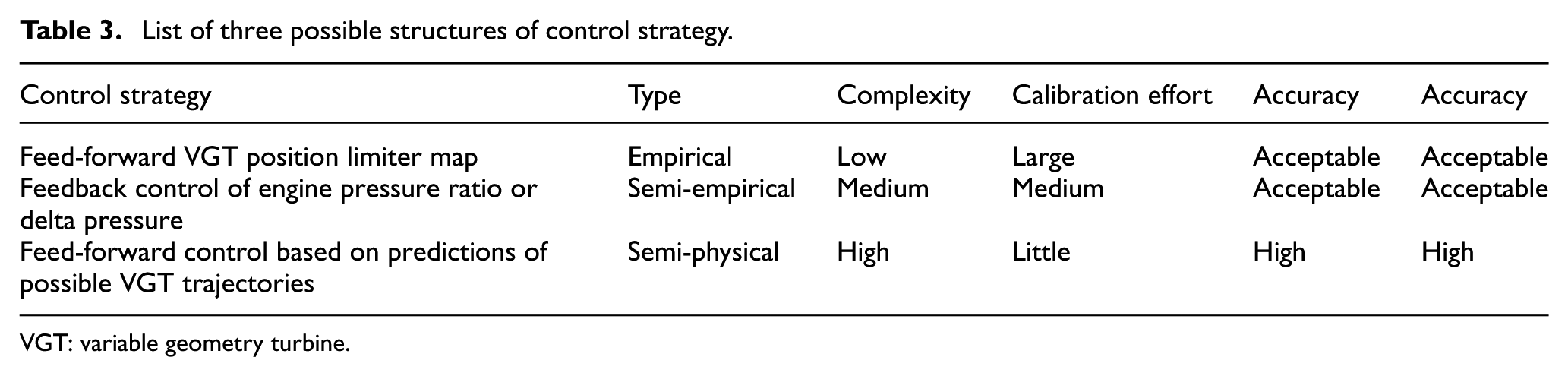
A number of possible alternative control strategies inspired by the existing ECU strategies and advanced technologies have been studied in this project. These are the possible strategies that could offer the fastest VGT turbocharger response during transient. These strategies are for transient operation, and they can be triggered when a tip-in is detected. In addition, if the target engine load during the transient is within the naturally aspirated region which does not require turbocharger acceleration, the engine volumetric efficiency, rather than turbocharger acceleration, should be the prioritised. Three possible structures of the control strategy for VGT turbochargers are compared below and listed in Table 3.
List of three possible structures of control strategy.
VGT: variable geometry turbine.
Feed-forward VGT position limiter map
This empirical approach sets the VGT opening based on a calibrated map, similar to the control of spark timing and valve timing. Because of the variations in the design of the VGT, each new VGT needed to be tested at a number of engine speeds. Thus, a look-up table can be formed to control the VGT position. The complexity of the look-up table can vary from 1D (engine speed) to two-dimensional (2D) (engine speed and load), depending on the complexity of the response of the system.
However, similar to the control of spark timing and valve timing, significant calibration effort was required. In addition, calibration of the VGT setting during transient involved additional dimensions, including time during transient and engine load steps, resulting in an enormous amount of calibration work and considerable controller deficiencies.
Feedback control of engine pressure ratio or delta pressure
This semi-empirical approach used intermediate parameters to correlate the VGT position limitation. Either the engine pressure ratio (time-averaged exhaust manifold pressure divided by time-averaged intake manifold pressure) or the engine delta pressure (time-averaged exhaust manifold pressure minus time-averaged intake manifold pressure) may be used as an intermediate parameter, as the engine volumetric efficiency and the turbocharger load were both related to these two parameters. Figures 5 and 6 show the correlation between the turbocharger speed rise and the two intermediate parameters. The maximum turbocharger speed rise at each stage and the corresponding engine pressure ratio/delta pressure are highlighted by the black line in the plots. Therefore, the black line indicates the time history of the optimum trajectory of the transients.
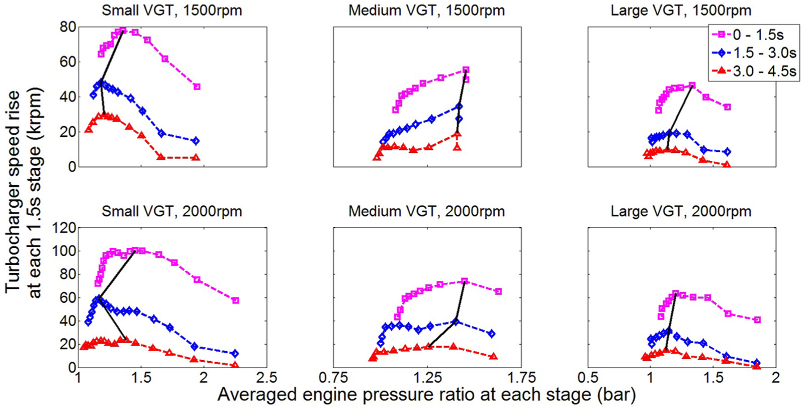
Correlation between maximum turbocharger speed rise and the engine pressure ratio.
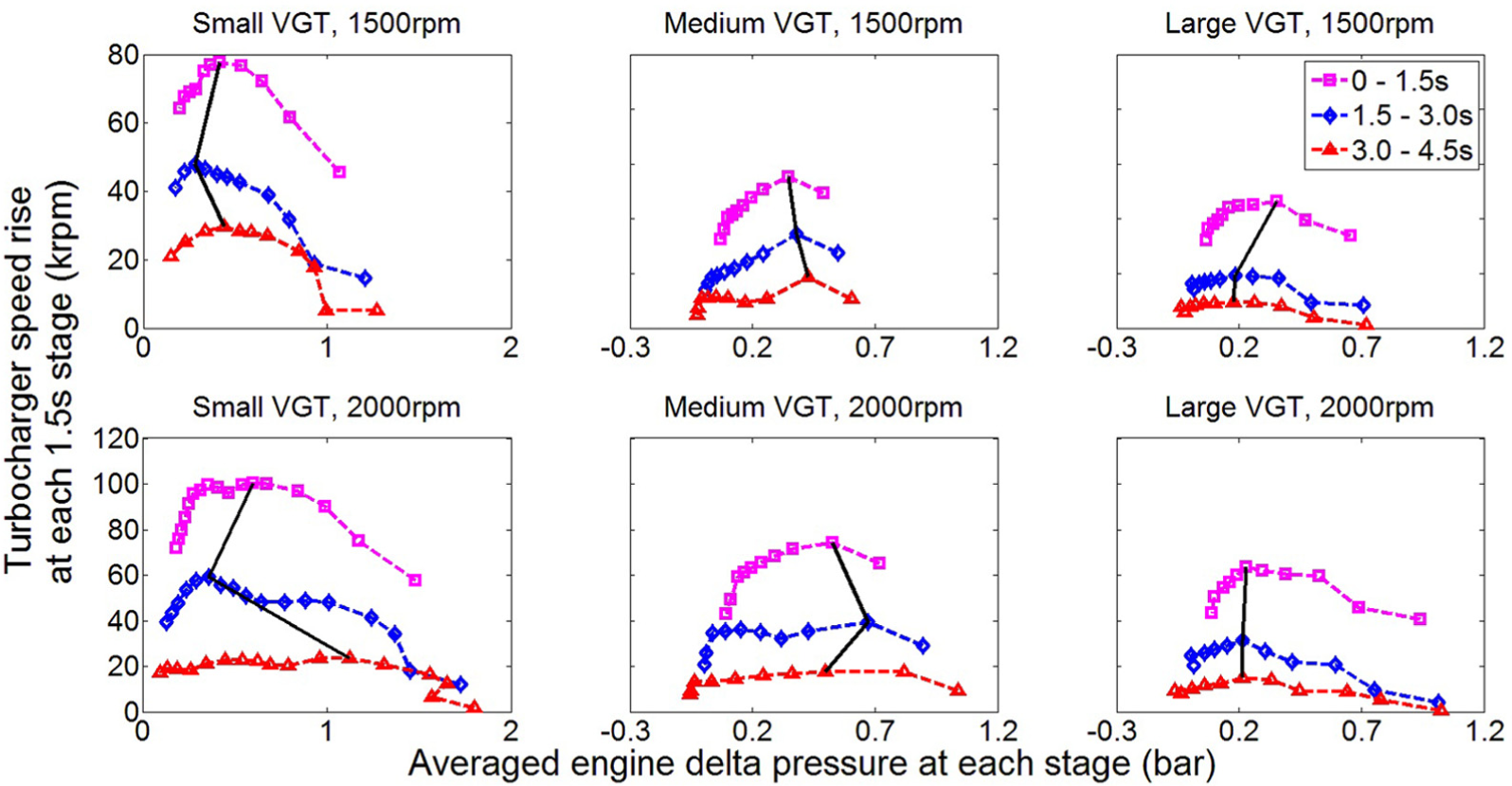
Correlation between maximum turbocharger speed rise and the engine delta pressure.
However, a large variation in the engine pressure ratio/delta pressure was found at the optimum VGT setting at each stage. Therefore, the turbine response could not be accurately captured using these two parameters. This was because the turbine behaviour was a function of a number of variables. In addition, since there is no direct control of the engine pressure ratio/delta pressure, a feedback structure was necessary. Thus, additional deficiency was introduced by this feedback controller.
Feed-forward control based on the prediction of possible VGT trajectories
Due to the complexity of the VGT behaviour, it could not be represented in a simple model. In addition, calibration of transient control is time-consuming. Therefore, a VGT model that represented sufficient physical fundamentals was necessary to improve the accuracy and to simplify the calibration.
This necessitated the use of a turbine mean-value model, which is a semi-physical model that predicts the turbine behaviours and performance. The model assumes that the dynamics in the turbine boundary conditions can be ignored, so that the computational time can be minimised for real-time uses. This can be achieved with sufficient accuracy. The simplicity and the predictability of the model enabled the prediction of possible VGT trajectories in advance in real time. Thus, the optimum VGT trajectory could be selected.
The turbine power was always maximised in the optimum VGT trajectory. Therefore, the VGT setting that could provide the maximum turbine power was sought at any time step and was chosen for the next time step. Therefore, the semi-physical feed-forward control strategy that is based on the prediction of possible VGT trajectories was selected because of the high level of accuracy, minimum calibration effort required, and the fast computational time.
Development of the semi-physical control strategy
Based on the non-dimensional representation of the turbocharger characteristics, 11 the structure for the calculation for each VGT opening has been proposed, as shown in Figure 7. The structure was based on the conventional approach for the calculation of turbine power using turbine expansion ratio, reduced mass flow, inlet temperature and pressure, reduced turbocharge speed, and turbine efficiency
where
where
where
Diagram of the estimation of turbine power for each VGT opening.
In order to predict the turbine operating points for all possible VGT openings, prediction of the engine volumetric efficiency was necessary for the estimation of turbine mass flow and expansion ratio, which also affected the engine boundary conditions and volumetric efficiency. Therefore, an algebraic loop was formed. Furthermore, estimations of turbine power were compared to find the VGT opening that provided the highest estimated turbine power.
Several parameters were measured directly from the engine model while the simulation runs. Therefore, the prediction of the turbine operating condition was dependent on the feedback measurements. Thus, the compressor behaviour at the current time step was used for the calculation of turbine power at the next time step, and the estimation of engine breathing was conducted using the empirical model of the volumetric efficiency. This simplified the tasks from modelling the behaviours of the entire engine to the modelling of the turbine behaviours.
Figure 8 shows the integration of the engine model and the strategy. The control strategy was formed of multiple sub-models, each of which has a standard structure (Figure 7). The required measurements were sensed from the engine model and sent to the control strategy. The optimum VGT position estimated by the control strategy was used to actuate the VGT during tip-in. Because of the use of these measured parameters, the computational effort required to run the mean-value models was minimal. Thus, this could run on ECUs in real time. Table 4 lists the parameters that were required to measure and model in this control strategy. These parameters have already been used in model-based calibration in modern ECUs. Therefore, this control strategy can be adopted on modern powertrains without significant modification.
Integration of the engine model and the control strategy.
Summary of the parameters required to measure and model for this control strategy.
The volumetric efficiency models in modern ECUs are complex, and several inputs are used. In addition, a large number of tests need to be performed to calibrate the model. Since this is usually performed in nominal engine calibration process, it is out of the scope of this project to build a complex engine volumetric efficiency model. Thus, a polynomial model with the input of engine mass air flow and engine pressure ratio was implemented for the validation of the control strategy in the 1D simulation environment. The data used to build this model were from the transient simulations performed on this engine.
The coefficient of determination of the engine volumetric efficiency model was over 0.98. This was sufficient for predicting engine volumetric efficiency. A model was built for each of the two simulated engine speeds. However, when implementing this control strategy for a real ECU, the existing model of engine volumetric efficiency in the ECUs should be used instead.
First-order filter has to be used to enable the turbine power calculation in GT-Power, since the inputs and outputs form an algebraic loop. To avoid oscillations and to simulate the response of the actuator on VGT turbochargers, the VGT position target was filtered, using a first-order filter with a time constant of 0.1 s, which is typical for turbocharger actuators.
Validation of the control strategy
Figures 9–11 demonstrate the comparison of the VGT position and the turbocharger response for the open-loop simulation, the simulation with the semi-physical control strategy, and the simulation with fully closed VGT after tip-in. The target turbocharger speed and engine brake torque (80% of maximum torque rise) are also marked in the plots. The control strategy was enabled after tip-in. The horizontal black lines represent the engine torque and turbocharger speed corresponding to the 90% of transient torque rise, which is one of the typical metrics in assessing engine transient response. In fact, the proposed transient control strategy is only needed before the turbocharger speed reaches the target (black line for 90% torque rise in this case). Therefore, the prediction beyond this point is irrelevant. It is shown that the optimum VGT trajectories of the three VGTs at the two engine speeds can be captured. The opening of the small VGT at a later stage of the transients was predicted.
Comparison of the VGT trajectories.
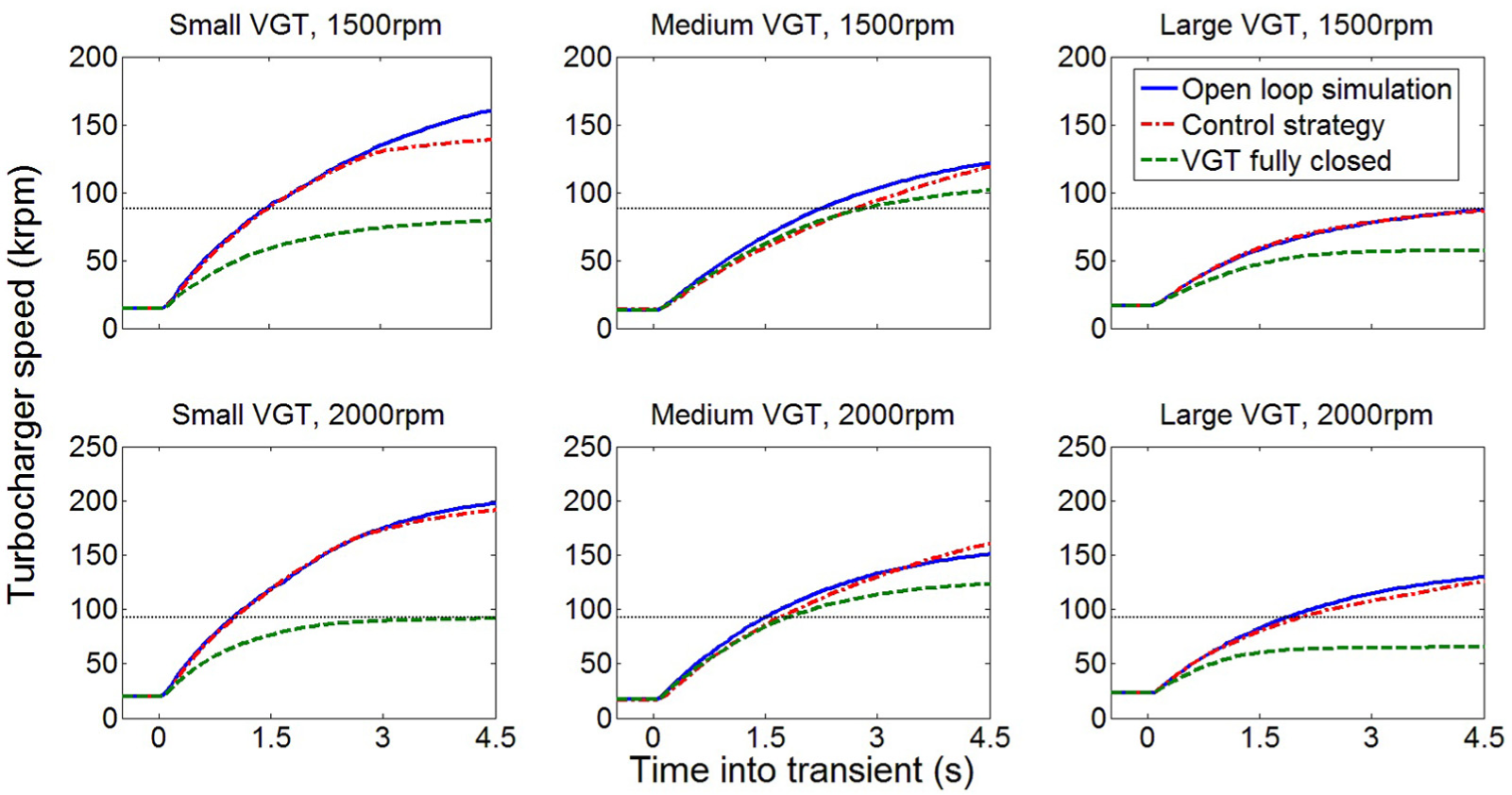
Comparison of the turbocharger response.
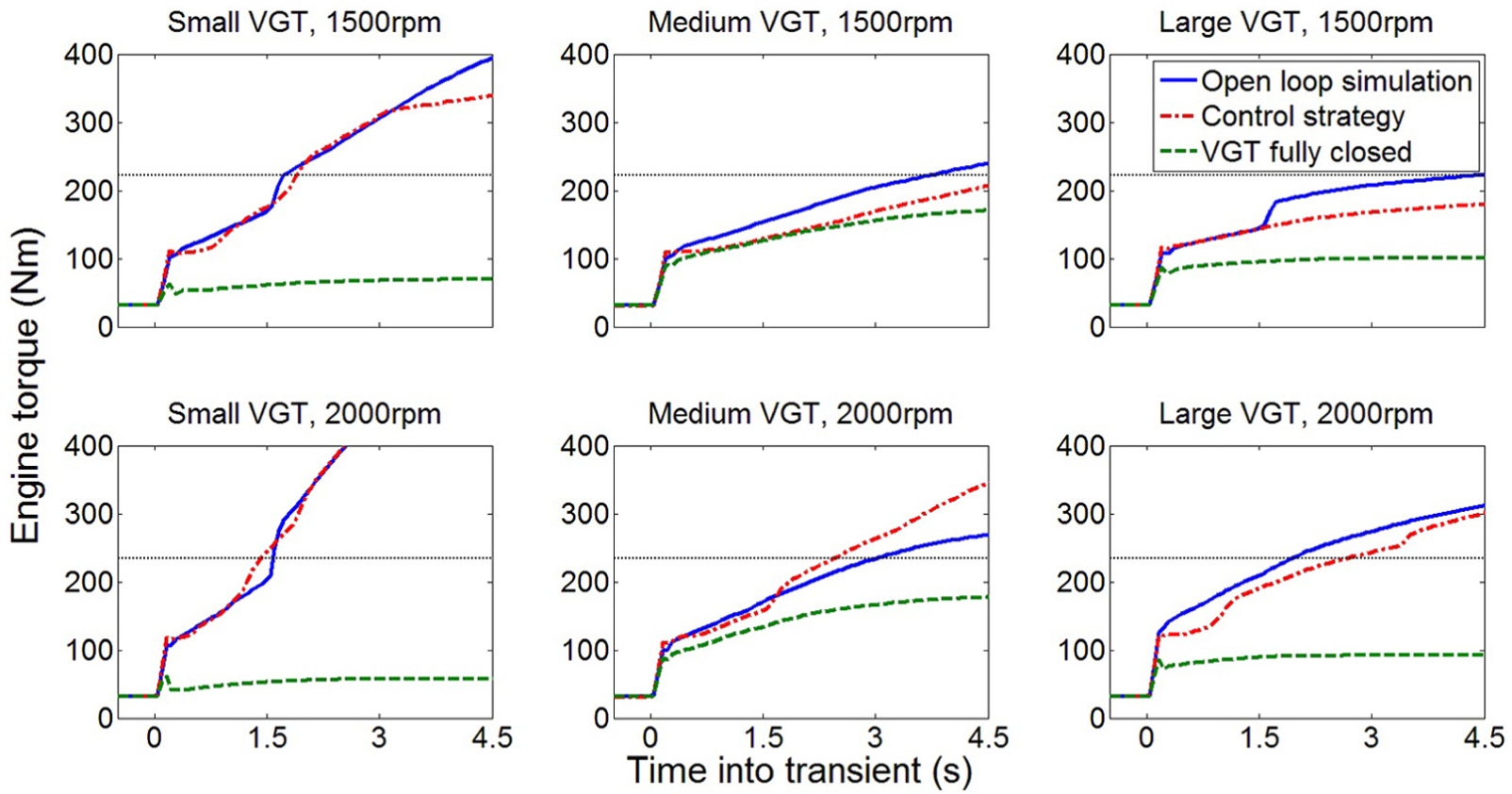
Comparison of the engine brake torque response.
The turbocharger responses as a result of the control strategy were close to the optimum responses detected from the open-loop simulations. It was found that the optimum turbocharger response could not be achieved in some cases, especially for the small VGT at 1500 r/min. This was because of the level of accuracy of the engine volumetric efficiency model. Figure 12 shows the data points used to fit the polynomial model. In the case of the small VGT at 1500 r/min, the engine operating point moved into the high-flow/low-pressure ratio region where no data were available. In this region, the engine pressure ratio was around 1. This resulted in inaccuracy in the estimation of the turbine power and hence the optimum VGT position.
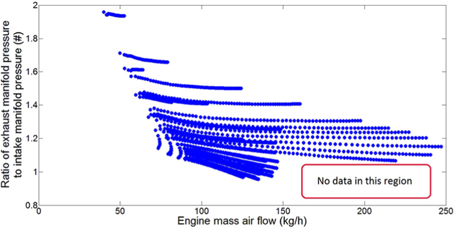
Data points used to calibrate the engine volumetric efficiency model at 1500 r/min.
Additional inputs to the model might be required to predict the volumetric efficiency accurately in this region. This could be improved when the polynomial model is replaced with the model used in the ECUs. Nonetheless, the turbocharger shaft power imbalance was small in this region, meaning that it was close to the end of a transient manoeuvre. The engine torque already exceeded the full-load torque curve at the point where the VGT trajectory started to deviate from the optimum trajectory. Therefore, the transient turbocharger acceleration was not affected.
In fact, when using this control strategy on real engines, the controller should be switched to steady-state operating mode when the torque target has been reached. The switching should be triggered either by a negative change in driver’s demand or when the turbocharge speed reaches target level, representing the end of a transient.
The turbocharger responses with fully closed VGT are also plotted in Figure 10. This was to represent the likely results if the control strategy was replaced with a conventional proportional–integral–derivative (PID) feedback controller, which would close the vanes to accelerate the turbocharger, since the non-monotonic response cannot be captured. Although using a VGT position limiter to assist the PID controller might improve the response, significant calibration effort would be required.
It is shown that the engine operating condition converged to a different point with fully closed VGT, and the target turbocharger speed could not be achieved. Table 5 summarises the time required to reach the target turbocharger speed corresponding to 80% of the steady-state engine torque. With fully closed VGT, the target turbocharger speed can only be achieved with the medium VGT. This was because the optimum VGT position for the medium VGT was only 5% below fully closed vane position.
Comparison of turbocharger response time between different controllers.
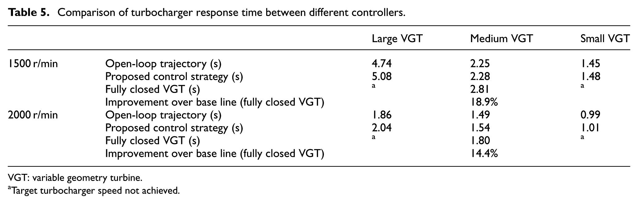
VGT: variable geometry turbine.
Target turbocharger speed not achieved.
In four of the six cases simulated, the target turbocharger speed could not be achieved with simple PID controller. In the two cases where PID controller could achieve the target turbocharger speed, the turbocharger response time was improved by 14%–19%. When the control strategy was enabled, the deficiency in the turbocharger response time compared with the optimum open-loop VGT trajectories was below 0.05 s for the medium and small VGTs, and it was up to 0.3 s for the large VGT.
As a result, the control strategy was able to capture the non-monotonic behaviours of the VGT turbocharger. Benefits have been shown compared with the conventional PID feedback controller. It is also expected that the structure of this control strategy can be used for other complex air-charging systems, such as two-stage turbocharging systems and air-path systems with both turbocharger and EGR. For example, two-stage turbocharging systems can be controlled with the behaviours of the two stages being estimated separately. This can be simulated by modelling a number of different positions of the bypass valves and VGT actuators.
Conclusion
In order to capture the complex behaviours of the VGT and to control it efficiently during transient operation, a semi-physical feed-forward transient control strategy was proposed based on the comparison between three possible strategies. The fundamentals and the capability of this control strategy were discussed in this article. The following conclusions can be drawn:
VGT turbochargers have the potential to further downsize and improve gasoline engines. However, control of VGT efficiently during transient is challenging due to the non-monotonic characteristics of VGT, which affects the engine volumetric efficiency that is critical on gasoline engines. Therefore, an advanced control strategy is needed to enable the use of VGT on gasoline engines.
Three different types of control strategies with different complexity, calibration difficulty, and accuracy have been compared in this article. Considerable calibration effort will be required if the empirical look-up tables were used for transient condition. In addition, the complex VGT behaviours cannot be correlated to an intermediate parameter. Thus, in order to capture the complex behaviours of VGT and to control it during transient efficiently, a semi-physical strategy that was able to predict the turbine performances of possible VGT settings in advance and also able to select the optimum opening for the next time step was proposed.
Using a validated high-fidelity engine mode, the transient control strategy was validated in simulation for the three VGTs at two engine speeds. The non-monotonic behaviours of the VGT were captured, and the optimum VGT trajectories can be achieved. In four of the six cases simulated, the target turbocharger speed and engine torque could not be achieved with a PID controller. In the other two cases, the proposed control strategy improved the turbocharger response time by 14%–19% compared with the PID controller.
Since the prediction of turbine power was based on mean-value turbine model, real-time operation was allowed. The parameters used as the inputs to the strategy were either measured or modelled in current ECUs on current modern passenger car engines. Therefore, the challenge in applying this strategy to the current ECU was minimised.
The structure of the proposed transient control strategy can also be used to control complex turbocharging systems, such as two-stage turbocharging systems and air-path systems, with both turbocharger and EGR.
Footnotes
Acknowledgements
The authors would like to thank project partners in the TurboCentre 2 project between University of Bath, Jaguar Land Rover Limited, Ford Motor Company Limited, and Honeywell Turbo Technologies, for the technical support and for the permission of publishing this article. The authors would also like to thank Powertech Engineering Srl for the support in engine model calibration.
Declaration of conflicting interests
The author(s) declared no potential conflicts of interest with respect to the research, authorship, and/or publication of this article.
Funding
The author(s) received no financial support for the research, authorship, and/or publication of this article.