
Abstract
The increasing availability of high-performance computing resources will allow scale-resolving simulations such as large eddy simulations to be used instead of unsteady Reynolds-averaged Navier–Stokes approaches, not only in academic research but also for engine combustion process development. The scope of this work is to highlight and discuss this transition to scale-resolving simulations and to propose a systematic approach for model development and application. The current and future scope of industrial and academic research is discussed especially with respect to cycle-to-cycle variations, which cannot be identified with unsteady Reynolds-averaged Navier–Stokes models. The individual processes along the cause-and-effect chain leading to cyclic variations of the combustion process are identified, and the current state of scale-resolving simulations and the required models with respect to these processes are discussed.
Introduction
The three-dimensional (3D) simulation (computational fluid dynamics - CFD) of fluid flow and combustion processes has become an indispensable part of the engine design process. Especially in the early development phase, sometimes even before hardware is available, simulation results allow engine performance to be predicted. In combination with experimental investigations and zero-dimensional (0D) or one-dimensional (1D) process simulation, 3D CFD can be used to evaluate specific engine parts (such as an intake port) or even whole concepts. This can help in identifying the most promising variants for further detailed studies. In fact, the combined use of experiment and simulation is a major contributor to reduced cost and development time.
The increasing acceptance and significance of 3D CFD as a reliable tool for the combustion process design is mainly due to two aspects. On one hand, significant progress has been achieved in describing physical and chemical processes such as the turbulent fluid flow, turbulent combustion or pollutant formation. Sometimes this even allows numerical predictions without parallel verification by experiments. On the other hand, there is a steady increase in the availability of high-performance computing (HPC) resources in combination with CFD software capable of using those resources efficiently. In general, the increased computing power could be used to reduce the overall simulation (wall-clock) time for a specific setup, keeping the same grid size and model setup. However, the more likely scenario is either to investigate a larger number of variants or operating points or to increase the grid resolution, for example, to reduce modeling uncertainties. This is illustrated in Figure 1, which is a schematic depiction of the load–speed map of an engine and the investigated operating points on the left and an example of the transition from unsteady Reynolds-averaged Navier–Stokes (URANS) to large eddy simulations (LESs) with increasing temporal and spatial resolutions on the right. The latter, in particular, is considered in the remainder of this article.
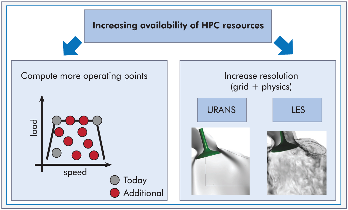
Two possibilities for using increasing computing resources in 3D CFD simulations of engine combustion processes.
Looking at a large number of points as compared to only a few characteristic ones allows us to evaluate aspects such as geometry design changes for the entire engine map. Usually, engine map-wide simulations are performed using 0D or 1D tools. For the in-cylinder processes, for example, charge motion, ignition, combustion, pollutant formation, wall heat transfer and knock, a number of simplified models are required, and they are usually calibrated using engine test bench data. Although not a standard approach, 3D CFD can also be used to analyze the combustion process for the entire map. 1 Such an analysis allows improved models to be developed for the 0D or 1D simulation,2,3 keeping in mind that they require CFD information for model calibration. Since only a small number of (characteristic) CFD simulations are required for calibration, combining 3D and 0D or 1D modeling is attractive for map-wide process optimization. Richard et al. 4 used an approach of this kind to develop a 0D combustion model based on the 3D CFD results and obtained good results regarding heat release, pollutant formation and even knock. Recently, Richard et al. 5 extended the model to account for cyclic variations. LES and particle-image velocimetry (PIV) results were exploited to identify cycle-to-cycle variation (CCV) mechanisms in a port fuel injection (PFI) engine as part of this study. These few examples already demonstrate clearly that 0D or 1D modeling approaches can be substantially improved using 3D CFD information making them less dependent on experimental calibration data, for example, for the Vibe combustion parameters from an engine test bench.
As mentioned above, the other option in the focus of this article is that of using increasing HPC resources for highly resolved simulations of engine fluid flow and combustion processes. This effectively shifts the current focus from Reynolds-averaged Navier–Stokes (RANS) to hybrid URANS-LES and LES or, in more general terms, to scale-resolving simulations (SRSs). A similar shift as expected here for engine simulation was observed several years ago for gas turbines. 6 Since the gas turbine process is noncyclic and no moving grids (in the combustion chamber) need to be considered, the step from URANS to SRS could happen earlier.
Thus, the scope of the remainder of this article is first to describe the different SRS approaches and their application for engines in section “SRSs for the engine combustion process design,” which confirms the increasing importance of this field. SRSs will without doubt become a valuable tool in the (industrial) engine combustion design process in the foreseeable future to understand specific phenomena for operating points with significant CCV. In section “Phenomenology of CCVs and the need for model development,” the phenomenology of CCVs is discussed, and the various contributing processes along the cause-and-effect chain are reviewed. This illustrates the need for developing and validating models on the academic side for resolutions covering the whole range from URANS to LES (see Figure 2). The availability of such models will be crucial for the industrial use of SRSs, and thus, a systematic approach for model development and validation will be proposed in section “Approach for systematic model evaluation and development for scale-resolving engine simulations,” and a corresponding example using a highly resolved simulation is presented in section “Example of how SRSs can support both model and process development.”
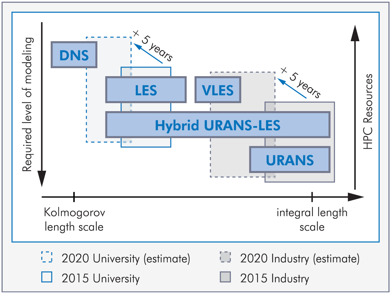
Schematic representation of different modeling approaches from URANS to DNS and the associated required level of modeling. Also shown are the current state of industrial and academic research with respect to engines and a prognosis for 2020.
SRSs for the engine combustion process design
URANS is currently the de facto standard in combustion process design and the approach which is most frequently employed in an industrial context. However, as mentioned above, especially in academic and also in some industrial research, SRSs are being used more and more often. The focus is placed here on the highest spatial and temporal resolutions achievable with the available computing resources for single operating points.
Figure 2 shows a schematic illustration of the modeling approaches currently employed. The resolved length scale ranging from the smallest turbulent (Kolmogorov) scale to the geometry-dependent integral scales on the right is shown on the abscissa, the required level of modeling on the ordinate. It is important to note that this figure specifically addresses flow modeling, but the extension to mixing or combustion is straightforward. For URANS, most of the fluctuations must be modeled, and the resulting modeling effort and the requirements with respect to model accuracy are at a maximum. However, for a sufficiently well-resolved direct numerical simulation (DNS), no turbulence model is required since all scales are resolved. In between these two extremes, a number of scale-resolving modeling variants relevant for internal combustion (IC) engines, namely, LES, very large eddy simulation (VLES) and hybrid URANS-LES, respectively, are depicted. It is important to note that Figure 2 is qualitative with respect to the absolute axis position. However, there is a clearly identifiable gap between LES and VLES. Furthermore, the hybrid approaches can span the whole range from URANS to LES. In general, it has to be noted that such a simplified representation is difficult for complex systems such as an engine, since the local resolution and the physical length scales can vary significantly. Even if the inner flow domain is resolved well within the inertial range (corresponding to LES), the resolution might not be sufficient for a wall-resolved LES, and the approach either becomes a VLES or specific wall treatments (e.g. URANS type) are used. The latter option, in particular, makes a unique classification difficult.
Pope7,8 proposed differentiating between LES and VLES based on the resolved fluctuations. For a typical LES (neglecting the near-wall considerations also discussed in the above reference), more than 80% of the turbulent kinetic energy is resolved. In VLES, the filter width, which is usually directly proportional to the local grid size, does not allow as much as 80% to be resolved. It is important to note that several other LES-quality indicators have been proposed;9,10 however, as mentioned by Baumann et al., 11 the application to engine flows is not straightforward. A systematic investigation of various quality indicators in engine LES was performed by Di Mare et al.; 12 this concluded that despite several shortcomings (mainly due to the complexity of the flow), most of them can be used to assess the local resolution quality, and they provide guidance especially where underresolution might occur.
It has to be noted that other classifications for engine SRSs were proposed. As an example, in the engine combustion network (ECN), 13 the terminology of low-, medium- and high-resolution LES approaches was introduced. The resolution or grid size used is directly associated with the intention, which can be either model development or validation or engineering development. High-resolution LES (minimal subgrid-scale (SGS) modeling, approaching DNS with more than 108 cells per cylinder) is used to determine the physics and develop or validate a model. Low-resolution LES (RANS-like resolution; currently 105−106 cells per cylinder) is used for engineering development and applications. Medium-resolution LES (currently 106−107 cells per cylinder) bridges these two extremes. A similar classification using the terminology “scientific LES” and “engineering LES” was suggested by Rutland. 14
Also represented in Figure 2 are hybrid URANS-LES models, which were originally developed in aerodynamic research. For wall-bounded turbulent flows at high Reynolds numbers, a URANS simulation requires grid refinement in a wall-normal direction. However, for wall-resolved LES, the grid needs to be refined isotropically in all three directions. This leads to a quadratic increase in the number of grid points with the Reynolds number in LES, whereas only a moderate logarithmic dependence can be expected in URANS. Spalart et al. 15 estimated that a (wall-resolved) LES of an airliner wing might be possible in four decades. Keeping this restriction in mind, for aerodynamic applications, a hybrid strategy using URANS modeling in the (underresolved) wall region and LES in the free stream was proposed. In engines, the situation is even more complex since both non-wall-bounded shear flows, for example, spray-injection and intake jet, and wall-bounded shear flows, for example, on the piston, valve and liner, are important. Thus, hybrid models using URANS resolution in the near wall (and other underresolved areas) and LES resolution in the free shear region can be beneficial for engine simulations. Initial investigations16–21 have produced promising results and shown the potential of this approach. However, it must be noted that there are at least a few major issues which require special attention. First, the transition between the URANS and the LES regions, sometimes called the gray area, is a potential weakness in all models, 22 especially considering the moving grid and complex geometries. Another crucial choice is the underlying URANS model. This is especially important since the wall boundary layers usually feature lower Reynolds numbers (compared to aerodynamic applications), and the overall flow structure including stagnation points can be very complex. Numerical results suggest that standard wall functions might not be applicable everywhere. 21 Initial experimental results showing the near-wall structure in engines were recently published.23,24 This will provide important validation data for developing engine wall flow models. Another aspect which further increases the modeling complexity of boundary layers is flame–wall interaction. A general review of available flame–wall studies is given in Poinsot and Veynante, 25 while more specific studies with respect to engines, putting the focus on fuel and pollutant emissions, can be found in Hasse et al.26,27 and Chauvy et al. 28 Currently, significant experimental efforts are being made to better resolve the near-wall processes,29,30 which are especially interesting for the improvement of hybrid URANS-LES modeling.
Finally, it is important to note that there are a number of studies already extending the limits shown in Figure 2, for example, DNS studies for a simplified engine configuration.31–34 Despite the significant differences with respect to current engines, many flow patterns such as large-scale vortex formation and interaction with the in-cylinder flow field can be studied taking advantage of the richness of the DNS data. Schmitt et al. 32 looked at jet breakup and how it is influenced by the residual flow motion in the cylinder to identify the origin of CCV. This backward analysis along the cause-and-effect chain, starting from the observation of CCV and going back to the responsible flow structures early in the cycle, could be the starting point for LES model evaluation and development.
Whatever the specific modeling approach, all scale-resolving models offer the benefit of an improved resolution of the energy-containing nonstationary flow structures and coupled thermo-fluid dynamic processes such as ignition, combustion and pollutant formation. For an engine simulation, this also means that multiple cycles must be computed, and phase-averaging is required comparable to that on an engine test bench, where multi-cycle and sometimes even multi-cylinder averaging is performed. This is an important difference to URANS, where a single cycle is usually assumed to be representative of the averaged cycle. This is another substantial difference between SRS and URANS and also has impacts on the required computational resources.
Based on the discussions above, the increase in HPC resources can be summarized as originating from three sources:
Increased grid resolution, larger grid size
Smaller time step size (Courant–Friedrichs–Lewy (CFL) number)
Multi-cycle simulations.
In general, only the first point can be compensated for completely using more CPUs or cores assuming perfect parallelization. However, points 2 and 3 are the main drivers of increased computing (wall-clock) and response times, although the last point can be partially compensated for since not all cycles must be computed consecutively but can be split into different parallel threads with modified initial conditions.35,36
In addition to the computational aspects discussed above, the SRS modeling strategies for the coupled processes such as mixture formation and turbulent combustion must be reconsidered in terms of resolved versus unresolved contributions. For all of these processes, suitable (subgrid or subfilter) models are required since at least some occur on nonresolved length scales. In combustion, the scales of the flame are usually smaller or of the order of the Kolmogorov scale and thus nonresolved in an LES. Since all turbulence–chemistry interaction models have a first-order influence, 8 reliable turbulent combustion models directly benefit from the improved resolution of the flow and mixing field. For non-wall-bounded turbulent combustion phenomena in particular, a number of high-quality models exist, and they are continuously being improved. A major contribution to this development is the close collaboration of experimental and numerical research in the framework of the Turbulent Nonpremixed Flame (TNF) workshop. An excellent review of the modeling approaches for turbulence, combustion, scalar transport and mixing as well as fuel spray for engine LES was given by Rutland; 14 thus, this topic is not discussed further here.
Based on the above discussion, the first step toward highly resolved engine simulations is the improved description of the fluid mechanic processes, and this already leads to a significant increase in computational requirements. Since the scope of this work is to investigate how these highly resolved calculations can be beneficial for the engine combustion design process, the next logical step is to decide which phenomenon (operating point) to consider. A straightforward choice is to consider operating points with both high cyclic variability and high relevance for the design or the overall combustion process. For gasoline engines, this corresponds to a high variance of the mean pressure, sometimes directly connected to engine roughness. Some well-known examples are catalyst heating (cold engine and late spark timing), part-load operation with high exhaust gas ratios and knock or super-knock. All of these are characterized by high cyclic dispersion, and they can only be addressed numerically with SRSs. URANS simulations can only predict trends but can never be quantitative. This fundamental difference has been highlighted in several review articles14,37,38 also showing that only SRSs can capture the phenomena leading to CCVs. This will be further investigated below.
It is also apparent from Figure 2 that a gap in terms of fluid flow resolution between academic research (scientific LES) and industrial development (engineering LES) does exist and will persist in the near future. Feasible grid sizes for engineering LES aiming at combustion process design will be significantly smaller than for scientific LES looking at single operating points of reference or benchmark engines. In fact, the aforementioned gap between academia and industry due to their different foci can be turned into an advantage by closely collaborating. Academia will produce highly resolved and nonstationary 3D datasets from scientific LES and can use this information for model evaluation and improvement, keeping in mind the resolution limits of engineering LES. These improved and resolution-adapted models will then be used and tested on a large variety of engines and combustion concepts in industrial process design. On one hand, this will directly provide feedback concerning modeling accuracy, but on the other hand, it will also identify future modeling needs. A systematic approach of this kind is the motivation here and is described in section “Approach for systematic model evaluation and development for scale-resolving engine simulations.”
Phenomenology of CCVs and the need for model development
As established above, SRSs offer the potential to numerically analyze cyclic variations of the combustion process. From an engineering point of view, CCV are clearly defined by the variation of the in-cylinder pressure curves and the associated coefficient of variation (COV) of the indicated mean effective pressure (IMEP). It is also well established that these CCVs depend on a significant number of individual processes such as the fluid flow, the spray, the mixture formation and the initial flame kernel formation, among others. However, the individual contributions and how their fluctuations affect the overall combustion process is usually not known or quantified. It should also be noted that a general classification is absolutely impossible due to the overall complexity of the process and the differences between the specific engines.
However, the understanding of how individual processes interact with each other is far more advanced; for example, the effect of turbulent fluctuations on the propagation speed of premixed laboratory-scale flames has been extensively investigated in the past. This allows us to quantify the contribution of turbulence to the burning velocity. However, this knowledge cannot directly be translated into a COV. To facilitate the analysis of such interactions and in order to quantify the individual contributions along the overall engine combustion process, a cause-and-effect chain is proposed in the next section. Individual processes along this chain can be identified for model evaluation, development and validation using specifically designed experimental or numerical setups. Improved models can then be combined to simulate the entire engine process allowing for a quantification of the individual contribution to CCV.
In addition to the detailed analysis of the individual contributions to CCV, the underlying models and their applicability for scale-resolving engine simulations must be considered. As mentioned by Rutland, 14 most of the models originate from URANS and thus require careful reevaluation for LES. One illustrative example concerns Lagrangian approaches for sprays. For increasing grid resolutions, the assumption of a large cell size with respect to the droplet size might break down, and both the modeling assumptions and the numerical treatment of droplet evaporation must be revisited. It has been shown that this becomes an issue in diluted sprays.39–41 The recommendation made by Luo et al. 39 to keep at least a ratio of 10 (cell size or droplet diameter) confirms that modeling and numerics in SRSs are strongly intertwined and cannot be separated as in URANS.
For SRSs, this highlights the need for a systematic approach, which includes model development on the process level and at the same time ensures applicability for the entire engine process (system level). This will be discussed further in section “Approach for systematic model evaluation and development for scale-resolving engine simulations.”
Cause-and-effect chain
Engine combustion is characterized by a large number of both parallel and consecutive processes. The cause-and-effect chain on the most general level is shown in Figure 3. Four consecutive major blocks are shown on the left, and examples of observable engine combustion phenomena with cyclic dispersion are illustrated on the right. It is evident that the intake flow has a direct influence on the cylinder charge (fresh mass and recirculated exhaust gases) and its in-cylinder motion (swirl and tumble). The importance of the charge motion, especially swirl and tumble, on the combustion process is well established both for gasoline and diesel engines. The design of the intake port considering manufacturing tolerances is a crucial step in the process development, which usually happens early in the design phase. Even though calibration, for example, valve timing, still has a considerable influence on the charge motion during engine operation, a careful design of the geometry is indispensable. An example of a SRS and how it contributes to model evaluations is discussed below in section “Example of how SRSs can support both model and process development.”
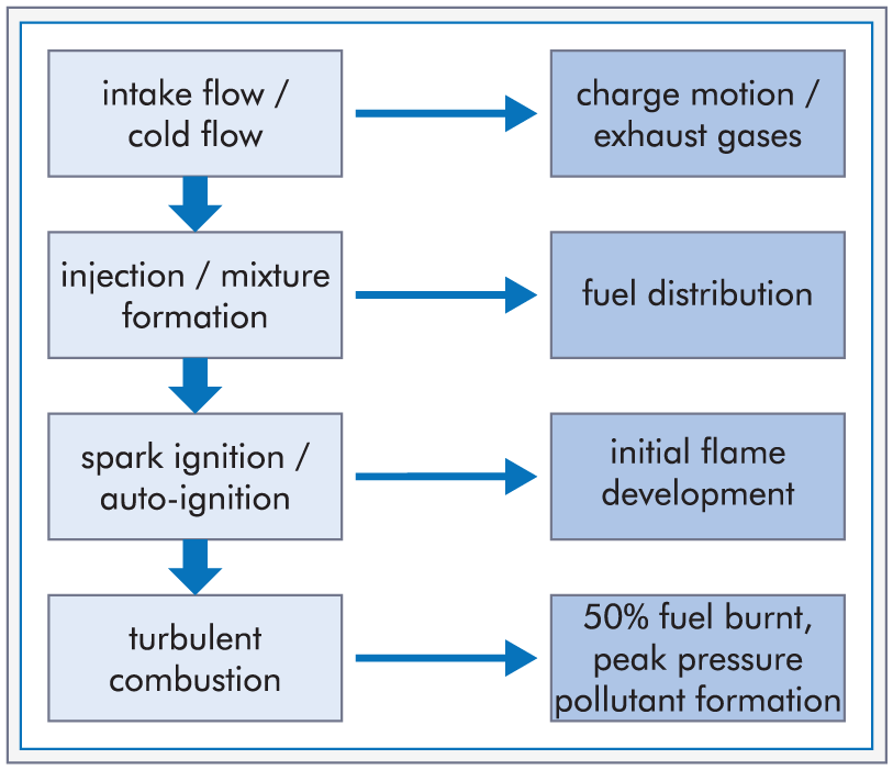
Cause-and-effect chain of engine combustion (left) leading to different cycle-to-cycle variations (right).
Following the intake flow, the next step, especially for modern direct-injection (DI) gasoline and diesel engines, is the spray and mixture formation, which directly influences the local flow structure and the fuel distribution. Cyclic fluctuations can originate from the interaction of the spray with the turbulent gas flow, while another important source of variability comes from shot-to-shot differences induced by the injection system itself. This becomes increasingly important for injection pulses with small amounts of fuel.
After the mixture formation, auto- or spark-assisted ignition takes place, which initiates the overall combustion process. For gasoline engines, the initial flame kernel development strongly depends on the λ and exhaust gas distribution in the vicinity of the spark plug. For late injections, especially, where the time for homogenization is limited, resulting significant cyclic differences with potentially too lean or too rich mixtures significantly influence the initial phase of burning. Such late injections are used even for “homogeneous” DI engines for special operating points such as catalyst heating.
Finally, turbulent combustion in the main charge and the burnout near the walls can exhibit significant CCV. Since the combustion progress directly translates to the observable pressure signal, variations in the cylinder pressure are often directly associated with CCV. However, this does not allow us to analyze the origin, which can only be identified by rigorous backward analysis, either from detailed optical experiments or multi-cycle SRSs. In addition, knock, super-knock and misfire are further stochastic processes which can quite evidently only be described quantitatively by numerical methods allowing CCV to be described. However, it must be mentioned—and this is briefly discussed below—that only very few CFD studies have tackled these issues due to the immense complexity, the associated modeling challenges and the high computational demands.
This brief discussion is meant to highlight the complexity of the process due to a large number of closely interacting nonlinear processes. To the author’s knowledge, there is no unified and commonly accepted assessment of the influence of each specific process along the cause-and-effect chain. This is not surprising, and in fact, it cannot be expected that a unified point of view like this will ever exist since the relative contribution of each process will depend on the specific engine or combustion process design or even operating point. However, a fundamental understanding of the process interactions, which will guide model development, is absolutely essential and can only be achieved with a combination of experimental and numerical efforts as established in the ECN. 13 A proposal for a systematic approach of this kind is discussed in section “Approach for systematic model evaluation and development for scale-resolving engine simulations.” Prior to this, some results of SRSs for the specific building blocks shown on the left side of Figure 3 are reviewed.
Engine flow
A number of investigations using SRSs of the intake flow have been published,18,21,42–45 and one example is discussed in more detail below in section “Example of how SRSs can support both model and process development.” An initial experimental investigation in a simplified square engine geometry with a moving valve and piston was performed by Borée et al. 46 with the intention of providing validation data for CFD simulation. The two-dimensional (2D) PIV velocity fields were used for comparison with SRSs.16,47 Both the experimental and the numerical data identified a large-scale tumble structure with strong cyclic variations of the position (precessing vortex core (PVC)). During the later stages of compression, the structure breaks down into smaller vortices (tumble breakdown). For gasoline engines, this breakdown directly determines the fluid flow in the vicinity of the spark plug, and cycle-to-cycle differences in the initial flame kernel development can be traced back to the breakdown process. Similar conclusions were drawn from 2D2C PIV data from an optical engine. 48 The flow was analyzed using both proper orthogonal decomposition (POD) and the finite time Lyapunov exponent (FTLE) technique 49 (to the author’s knowledge applied for the first time in engine flows). All of these publications emphasized that PVCs cannot be captured using URANS approaches.
Another simplified engine with a fixed valve and a moving piston to study cold engine-type flows was experimentally investigated by Morse et al. 50 This dataset was one of the first to be used for an LES study of engine-like flows. 51 More recently, this setup was even investigated using DNS by the ETH Zürich group31–34 including studies of the jet breakup, boundary layer wall heat transfer and thermal stratification. Such data are perfectly suited for model development and validation (see section “Approach for systematic model evaluation and development for scale-resolving engine simulations”).
SRSs of realistic engines under motored conditions have recently been published by several groups.11,18,52–57 Especially, Yang et al. 58 emphasized the significant benefits of SRSs by comparing them directly to URANS results.
Injection and mixture formation
As discussed above, mixture formation is a crucial step for the subsequent combustion process. The fuel spray interacts with the turbulent in-cylinder flow. Fluctuations resulting from this interaction as well as those introduced from the injection system itself (rail pressure, needle lift, cavitation, etc.) can have a significant influence on the homogenization of the fuel–air mixture. This was investigated by the Darmstadt group in a series of publications.35,36,59 A backward analysis to quantify the influence of the in-cylinder flow on the spray formation was proposed by the same group.60,61 In these studies, the analysis was based on experimental data. The combined use of high-resolution experimental and numerical 3D data could be even more promising.
In the ECN 13 framework especially, a number of LES studies can be expected in the future due to the availability of high-quality experimental datasets for diesel sprays in high-pressure, high-temperature, constant-volume chambers. Most of the studies so far have used URANS approaches (see Bhattacharjee and Haworth 62 for an overview); however, initial LES work has been published.63,64 Also, with the recent introduction of the gasoline injector (spray G), experimental and numerical data will become available.
Combustion and pollutant formation
A number of studies have looked at cyclic combustion variations for stable operating points.65–70 Comparing the in-cylinder pressure between SRSs and experiments allows us to make an initial evaluation of the predictive capability of LES. Such comparisons using global quantities are more difficult for the other processes in the cause-and-effect chain, as mentioned above, since no easily accessible quantity such as the pressure is available. One specific advantage of high-fidelity simulations is the potential to simulate and analyze critical or unstable operating points such as misfire. As explained by Drake and Haworth 71 based on experimental evidence, the initial flame kernel development strongly depends on the local mixture composition and velocities in the spark plug vicinity; see also the discussion above. Similar conclusions were drawn in Goryntsev et al.72,73 based on the LES results.
Pollutant formation, although directly connected to the combustion process, has not yet been the focus of SRSs. In contrast, looking at URANS-based studies, the detailed consideration of soot, NO x , unburned hydrocarbons or CO is an integral part of the investigations. This reflects the fact that understanding the pollutant formation processes themselves and predicting not only the overall amount but also how this amount is influenced by the engine operating strategy is a crucial step in the design of a combustion process. Thus, the question arises whether pollutant emissions exhibit significant cyclic fluctuations and, if so, whether this can be predicted with sufficient accuracy. Bearing in mind that it is difficult to experimentally resolve the gas composition for single cycles, the relevant issue (e.g. for the overall system performance and the catalyst design) is whether the average of the single cycles is close to the pollutant emission calculated based on an average cycle. Due to the strongly nonlinear coupling of mixture formation, combustion and the pollutant formation processes, a finding of this type is not to be expected. To the author’s knowledge, this aspect has not been investigated in the literature, although there is evidence that the cyclic variations can be significant. Zschutschke and Hasse 74 investigated catalyst heating, which is an important operating point for vehicle driving cycles since the catalyst has not yet reached conversion temperature, and thus, for example, NO x cannot be reduced, with a COV of the IMEP larger than 10%. They showed that significant in-cylinder NO x differences between individual cycles can be expected. Since catalyst heating is characterized by extremely delayed combustion and very high combustion CCV due to late spark timing, the corresponding engine-out NO x vary significantly. In fact, for an operating point of this kind, a standard URANS approach can be expected to fail to capture the cycle-averaged pressure.
Furthermore, there is considerable experimental evidence that soot formation differs from cycle to cycle. Optical engines and visible soot radiation allow both local and global differences to be detected. One of the first studies on DI gasoline engines confirmed these large cyclic fluctuations, 75 and a number of factors can be identified. The ignition or burn delay is known to significantly affect the formation of soot particles, for example, a short ignition delay means less time for mixture homogenization. However, it was shown that variations of the exhaust gases influence the formation of particles. 76 The direct influence of the spray and the subsequent droplet breakup was shown by Fatouraie. 77 Finally, another process currently not extensively investigated in the openly available literature is pool-fire. In DI engines, especially, the fuel jet hitting the piston (especially during a cold start) can form a liquid pool on the surface leading to a nonpremixed flame producing significant amounts of soot, 78 which vary from cycle to cycle.
Knock and abnormal combustion
Knock and more recently mega- or super-knock 79 in downsized gasoline engines is a long-standing issue. Despite the highly stochastic nature of this phenomenon, most CFD studies so far have been URANS-based.80–83 These studies can only be qualitative and can only predict trends, although including additional information from a probability density function was shown to improve results with respect to quantification. 80 It is interesting to note that up to 2011, no LES studies on engine knock were published at all, as pointed out by Rutland. 14 Since then, some initial attempts to model engine knock using LES have been reported.84–86 Although significant improvements have been achieved in describing the fluid flow, mixture formation and the combustion process leading to end-gas auto-ignition, knock prediction was still only qualitative since auto-ignition is only a necessary but not a sufficient criterion for knock, as pointed out in a series of articles by Bradley et al., 87 Gu et al., 88 Bradley and Kalghatgi 89 and Kalghatgi and Bradley. 90 The first promising works to predict engine knock were published only recently.91,92 Although only based on 15 cycles, theses studies clearly show the enormous potential of scale-resolving studies in understanding engine knock and how it is influenced by the different processes along the cause-and-effect chain.
Approach for systematic model evaluation and development for scale-resolving engine simulations
In the previous sections, the possibilities and benefits of published and future SRSs were briefly discussed. The following section proposes a methodology to evaluate, develop and validate the necessary models, for example, for the fluid flow, spray, mixture formation and combustion. This approach directly follows the systematic guidelines by Pitsch and Trisjonoa 93 for developing an LES combustion model from DNS data. Their approach followed a tier-based validation strategy that includes a broad base of unit problems and performs the corresponding validation through a hierarchy of benchmark cases.94,95 Interested readers are especially referred to follow-up works that considered verification and validation (V&V) in CFD.96,97 These ideas are used here as a starting point for model development and validation for scale-resolving engine simulations, which can span the whole range from LES, hybrid URANS-LES to VLES. It will also be briefly explained below that even URANS approaches can benefit from a strategy of this kind.
Developing and validating models for SRSs is important in the context of engines for a number of reasons. As explained above, a number of complex physical and chemical processes interact along the cause-and-effect chain in engine combustion. In addition to the turbulent single and multiphase flow, combustion at widely varying pressures and temperatures as well as the complex moving geometry in a cyclic system are a challenge for a stringent validation procedure which goes beyond comparing experimental and numerical pressure curves. While in URANS simulations, the computing time for a single cycle might still allow for some model parameter adjustment, this becomes prohibitive for multi-cycle SRSs. The individual models must be validated and/or calibrated prior to this simulation, and this requires well-defined numerical or experimental benchmark cases, which ideally isolate the effects under consideration. Despite the fact that the modeling depth and thus uncertainty reduces with the flow resolution (see Figure 2), a number of processes such as turbulent combustion or spray formation still require comprehensive modeling due to the associated small scales, see the discussion above.
The aforementioned approach for model development and validation derived from the suggestions by Pitsch and Trisjonoa 93 and specifically adapted for scale-resolving engine simulations is shown in Figure 4. In general, the pyramid is divided into three parts: the system level, the process level and the lowest level of unit problems, respectively. From top to bottom, the relevance for the system decreases, whereas the amount of data (richness) significantly increases.
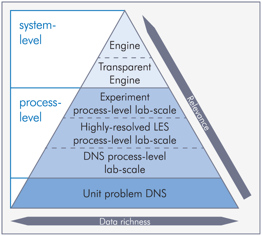
Hierarchy from system scale to unit-problem DNS for model development for scale-resolving engine simulations adapted for engines based on Pitsch and Trisjonoa. 93
On the system level, two types of engines can be identified. On the top, thermodynamic single- and multi-cylinder engines are found. These engines are usually equipped with pressure indication and exhaust gas measurement. This provides the minimum amount of data, which, however, is often used as the only data for comparison with numerical results. Optical engines are found on the level below, offering more in-cylinder information. Two very well-known examples currently actively used for model evaluation are the transparent combustion chamber (TCC) engine from the University of Michigan98,99 and the Darmstadt engine.60,100–102 These engines are very close to a real engine; the main differences are due to necessary geometric modifications, for example, fireland crevice or compression ratio, and the operating conditions. While it is clear that the engine cannot be operated at a high load, another, more subtle difference is the wall temperature. Due to the short operation window, usually only a few minutes, the engine never reaches steady operation temperatures. On the fluid flow side, this leads to differences in the fresh gas mass, wall heat transfer, blow-by and compression pressure, among other things. Nevertheless, the data from optical diagnostics are invaluable to understand the interactions inside the cylinder. One example is backward analysis along the cause-and-effect chain to identify the source of CCV 60 or the identification of coherent flow structures using advanced methods such as POD20,52,53,55,56,103–107 or FTLE. 48 The data from these benchmark engines have become the de facto reference datasets. To ensure a quantitative comparison, the CFD simulation should take into account all the effects mentioned above such as increased fireland crevice volume, although they are very specific to optical engines and may not be relevant or applicable for thermodynamic engines.
The process level is split into three main blocks, namely, experiments, highly resolved LES and DNS, respectively, of (at least partially) isolated engine processes on a laboratory scale. This level is most important, and in fact, this is where the most fruitful experimental–numerical collaborations already exist, for example, in the ECN, 13 the TNF workshop 108 or the International Sooting Flame (ISF) workshop. 109 In contrast to previous definitions of the process level, for engines both experiments and simulations (LES and DNS) can serve as a data source. Compared to the full engine, the process level attempts to break down the complexity of the full engine cycle into several parts by looking, for example, at the spray or intake flow in detail, corresponding to the building blocks shown on the left side of Figure 3. Looking specifically at the ECN, a strong focus is currently placed on diesel and gasoline sprays in constant-volume chambers. The injectors are well characterized, even allowing the internal nozzle flow to be calculated, since both the nominal and the real geometries have been made available to the research community. The injectors are passed between the participating institutions for experimental investigations. Common rules for data postprocessing have been put forward, which can also be applied for the numerical simulations. Systematic variations of the operating points (pressure, temperature, atmosphere, etc.) are specifically valuable for model comparison. Other datasets relevant for engine combustion include the laboratory flames, for example, from the TNF workshop or engine-related flow bench data to characterize the intake flow.21,110
Simulations of these systems can be performed at varying resolutions. As mentioned above, for engine combustion process design, the whole range from URANS-VLES to full-scale LES should be considered. Specifically, high-resolution LES with minimal turbulence modeling might serve as a reference dataset similar to a DNS. This dataset can be used in other applications for turbulence model evaluation. An example of this kind is discussed in section “Example of how SRSs can support both model and process development.” When looking at DNS, in addition to primary breakup or turbulent combustion cases, for example, a very promising set of calculations was performed by the group in Zürich31–34 looking not only at the cold flow but also at wall heat transfer. Such data provide a unique information depth and are ideally suited for comparison with LES. The full 3D data, both instantaneous and cycle averaged, will allow turbulence modeling closures to be tested on varying grid resolutions. Furthermore, the effect of moving grids, equivalent to time-dependent filter sizes in an LES, can be studied. Although it is quite clear that the modeling effort, for example, for the turbulent viscosity, decreases for higher grid resolutions, to the author’s knowledge, no systematic evaluation of different SGS models has been published for this dataset. Even if similar results can be expected for the free shear flow with sufficient resolution of the turbulent motions, differences are to be expected for the models close to the walls. While standard hybrid models or LES approaches require or introduce a special wall treatment, recently proposed models, such as wall-adapting local eddy viscosity (WALE) 111 or the σ-model, 112 are formulated such that they yield correct scaling toward the wall given sufficiently fine grid resolutions.
The lowest level in the pyramid in Figure 4 is the unit-problem DNS. Datasets are available for turbulent combustion modeling, for example, from the Sandia group.113,114 The DNS of primary atomization becomes feasible115–119 at conditions more and more relevant for engines. For this specific application, the parallel development of suitable numerical methods is almost as important as the availability of HPC resources.
Based on the discussion above, a sequence of seven steps (with a preceding step 0) is proposed as a systematic approach to model development, evaluation and validation in the engine context:
Step 0—Identification of the problem from a thermodynamic engine: The onset of the model development is a phenomenon observed for a system-level thermodynamic engine. This can be, for example, high CCV for certain operating parameters or hardware variants. In order to understand the underlying physics, SRSs are to be performed, and the required models are to be developed using the methodology described below.
Step 1—Transparent engine: As a first step, relevant operating points should be identified for an optical engine on the system level, where the same phenomenon can be found. However, it has to be kept in mind that depending on the specific phenomenon of interest, these operating points can also be derived from a thermodynamic engine, for example, knock investigations might only allow (at most) endoscopic access to the combustion chamber.
Step 2—Regime identification and analysis based on URANS-LES of the transparent engine: The operating point identified in step 1 is simulated with either a URANS or LES approach. The results are used to identify the relevant regimes, for example, for combustion or spray formation, on the process level. An example of this kind of analysis can be found in Linse et al., 1 where the regime of turbulent premixed combustion is characterized in the Peters–Borghi diagram 120 based on the turbulent and chemical time and length scales obtained from a 3D URANS simulation. The results clearly show that the dimensionless numbers change significantly during the cycle due to the changes in temperature and pressure and that the combustion in modern turbo-charged gasoline engines takes place in the thin-reaction zone and corrugated flamelet regime. Such information is crucial to identify the relevant experiments or DNS conditions for step 3.
Step 3—Selection of process-level laboratory-scale experiment or DNS: For engines, both experimental and DNS data can be suitable for process-level investigations. Some straightforward examples are flow bench investigations21,110 for inflow characterization or constant-volume combustion chamber experiments such as those performed within the ECN context. Both ensure system relevance using application-related hardware such as the cylinder head or the injection systems. For the latter, this ensures realistic conditions for the spray and mixture formation, where the surrounding gas phase can be adjusted to match a variety of engine operating conditions. The use of reference fuels such as n-heptane, n-dodecane or iso-octane is crucial and removes uncertainties for the subsequent comparison with the numerical simulations. DNS data can also come from a variety of sources including the simulation of simplified engines 31 or split injections specifically targeted to diesel conditions. 121
Step 4—LES of experiment or DNS identified in step 3: After selecting the experiment or DNS in step 3, the same setup is simulated, preferably with LES. This allows an initial evaluation of the model to be improved or evaluated. The model is expected to break or at least clearly show potential for improvement. Since the final application is on the system level and the focus of this work is placed specifically on the support of SRS for combustion process design, corresponding VLES and URANS simulations should be performed as well. This allows investigators to judge the quality of the model based on different available flow resolutions. This is important since the model might be formulated in a dynamic manner to account for differences in the local resolution.121–125
Step 5—A priori model analysis and development: The availability of a process-level experiment or DNS from step 3 should be used in an a priori analysis of the model to identify model deficiencies responsible for the differences found in step 4. This knowledge is directly used in model development, which can either incorporate new physical processes or modify or improve the existing modeling framework. The irreducible error of the model should be quantified as shown in Pitsch and Trisjonoa. 93
Step 6—A posteriori model analysis and comparison to experiment and DNS: The new and improved models are coupled to the LES code and are used for similar CFD studies to those in step 4. A classical a posteriori analysis then allows the model improvement to be evaluated and the model to be subsequently validated (in combination with the quantified irreducible error from step 5). Usually steps 4–6 represent an iterative process.
Step 7—CFD simulation of the transparent engine and evaluation or validation of improved models: Finally, the new and/or improved models are combined and integrated into the full engine simulation framework. This allows computations to be performed on the system level with new approaches systematically developed and validated as described above. Again, these simulations can cover a broad range of resolutions ranging from URANS to LES. A comparison of this kind allows the importance of flow resolution for specific engine combustion processes to be assessed. Although it is quite obvious that increasing the resolution will offer benefits due to reduced modeling efforts, different applications (or issues) might benefit differently from this additional resolution.
These seven steps are shown as a sequence in Figure 5 as a visual representation of the above description. The unit-problem DNS, although shown in Figure 5 with dashed lines, was not included in the above discussion. For engine combustion, the limits between unit problems and process level are continuous; for instance, the DNS of a stratified flame 126 could be attributed to both levels, for example, if the stratification in the DNS is close to a mixture condition identified in step 1. A review of available DNS datasets, mostly at the unit-problem level, can be found in Barlow et al. 108
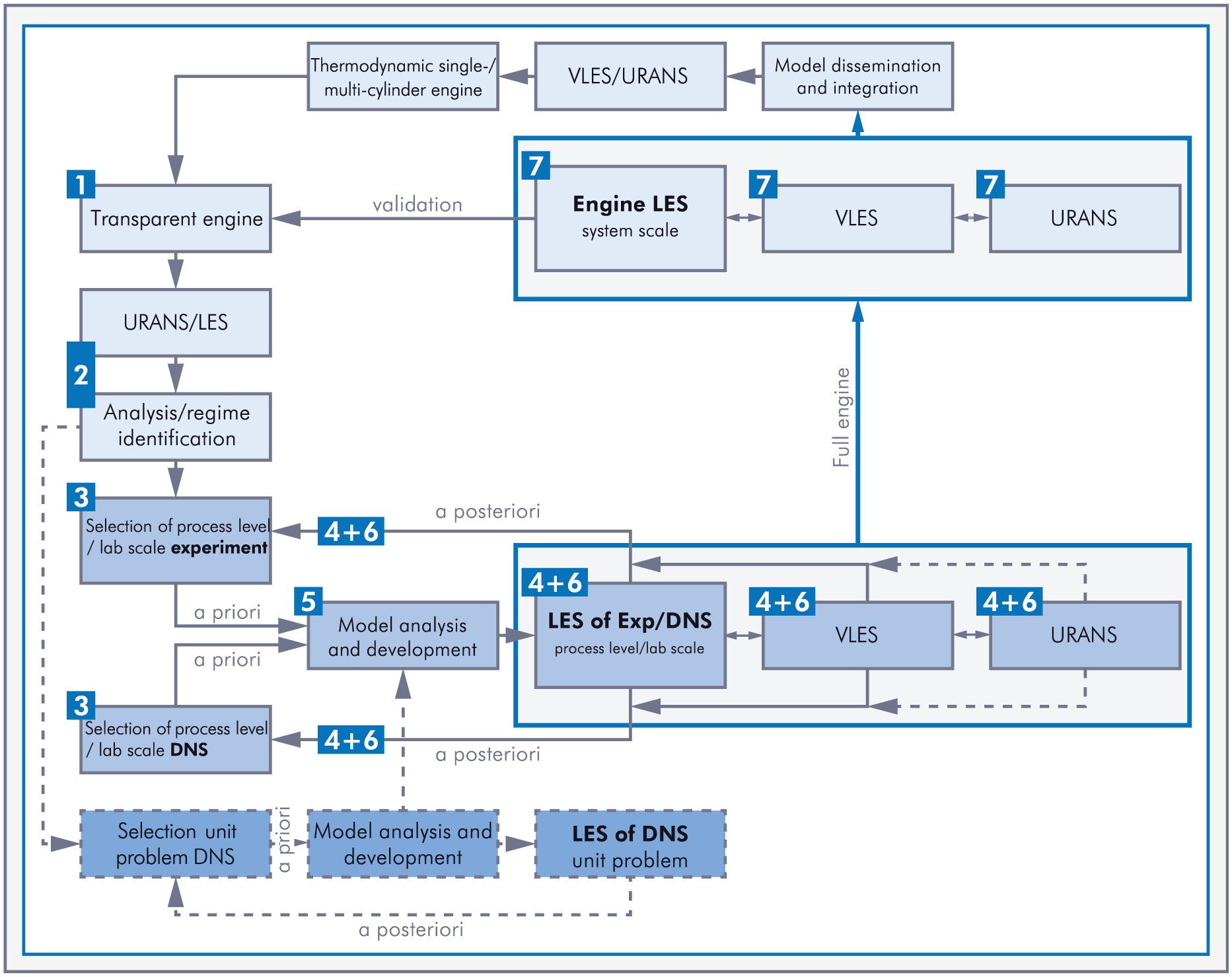
Visual representation of the model development workflow for scale-resolving engine simulations. As in Figure 4, different color shades indicate the system level, process level and unit-problem DNS levels, respectively.
Although the discussion is deliberately kept generic here, it is clear that the approach described above ensures that the process initially starts on the system level (step 1), then consecutively steps down the pyramid (steps 2–6) before it finally returns to the system level (step 7; see Figures 4 and 5).
Example of how SRSs can support both model and process development
In the following section, the flow through an intake port of a modern gasoline engine is considered. According to the pyramid shown in Figure 4, this investigation looks at flow phenomena on the process level. The close connection to the system level is ensured using a realistic (close to series production) cylinder head. SRSs of the intake port flow are performed with different grid resolutions, and the results are compared with PIV data. This specific application is particularly interesting because
The intake flow is at the beginning of the cause-and-effect chain (see Figure 3) and thus potentially influences all subsequent processes;
Both the numerical and experimental investigations (the latter mostly only into global quantities such as discharge coefficients and tumble number) are a standard part of the design process;
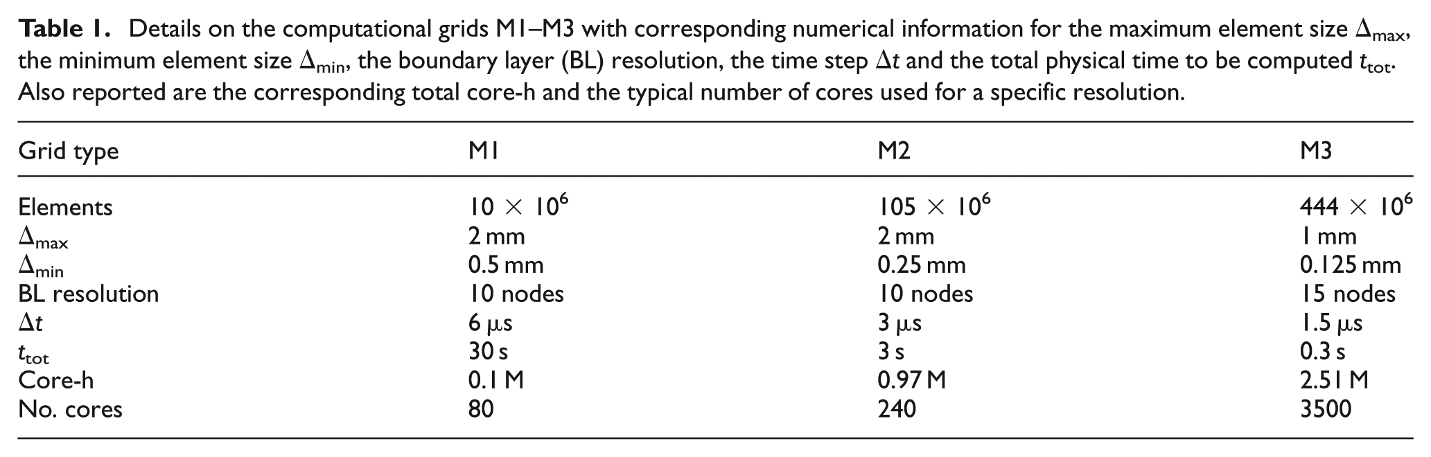
Since the flow is noncyclic, the advantages of SRSs with respect to URANS approaches can be demonstrated without the need for multi-cycle simulations. Furthermore, the achievable grid sizes with almost 0.5 billion elements and local grid resolutions around 100 µm (see Table 1) are currently beyond the reach of full-cycle simulations.
Details on the computational grids M1–M3 with corresponding numerical information for the maximum element size Δmax, the minimum element size Δmin, the boundary layer (BL) resolution, the time step Δt and the total physical time to be computed t tot. Also reported are the corresponding total core-h and the typical number of cores used for a specific resolution.
The general experimental and numerical setup is described in detail in Hartmann et al. 21 and will only briefly be reported here. A modern series-production cylinder head with a machined tumble edge is investigated on a stationary flow test bench with a fixed valve lift of 5 mm. For this specific setup, optical access was achieved not only in the direct vicinity of the valve but also partially in the intake port (see Figure 9 for an outline of the area with sufficient illumination). Most of the experimental test rig was considered in the setup of the computational domain. The measured pressure, temperature and mass flow rate were used as boundary conditions.
Simulations were performed using ANSYS CFX R15 with second-order spatial and temporal schemes. Three different grids were created; their main characteristics are given in Table 1. All grids use tetrahedral, hexahedral and prismatic elements. While prism layers at the walls can be used to locally refine the wall boundary layer, the flexibility of tetrahedral elements can be used to easily decrease the element size in the high-shear jet region (see Figure 6). While the grid M1 is on the border between URANS and VLES, M2 and M3 are well within LES limits but differ in the valve region resolution by a factor of 2 with respect to the edge length. Furthermore, M3 has an increased boundary layer resolution. Other numerical parameters such as time step size, which is directly determined from the CFL number, are also reported in Table 1, along with the required core-h for the specific grid resolution. The required resources for grid M3, in particular, show that scale-resolving engine simulations are performed in a massively parallel manner using 3500 cores.
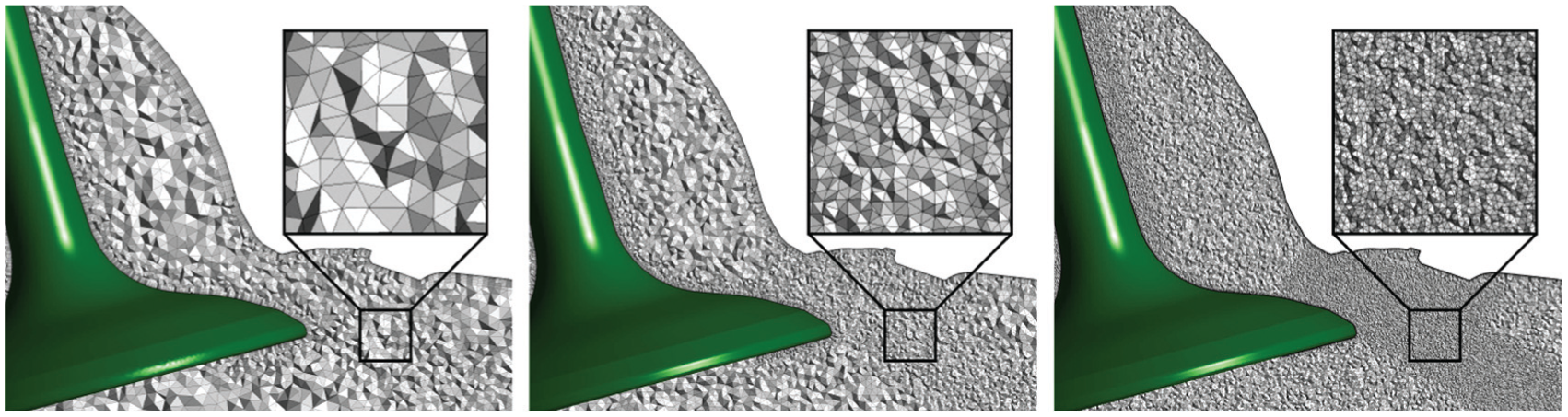
Comparison of the near-valve grid resolution. From left to right: M1 with 10 million elements, M2 with 105 million elements and M3 with 444 million elements.
In addition to the scale-resolving model, the two URANS models k–ε 127 and shear-stress transport (SST) 128 are employed. SST blends between the k–ε and the k−ω 129 model. It must be noted that even M3 is critical in terms of boundary layer resolution for a wall-resolved LES, and thus, we choose detached eddy simulation (DES)-SST16–18 as a hybrid URANS-LES approach in this work. As discussed above, this approach ensures two-equation URANS behavior in underresolved areas (in the sense of a sufficiently resolved LES), which not only includes the wall region but potentially also other flow areas.
Figure 7 shows the instantaneous velocity and vorticity fields of the URANS (SST) and the SRS on the three different grids. From these plots, it is obvious that the increased grid size allows us to resolve significantly more dynamic flow structures, which do not have to be modeled. Even the difference between URANS and SRS-M1 is notable and significant. Looking at a series of snapshots both from the PIV experiments and the SRSs, significant jet-flapping can be identified. This flapping was also observed earlier for a simplified engine geometry16,46 leading to significant differences in the formation of the large-scale tumbling motion from cycle to cycle. No flapping of this kind can be identified in the URANS simulations, showing that there is a very stable and stationary jet which, however, differs between the URANS approaches.
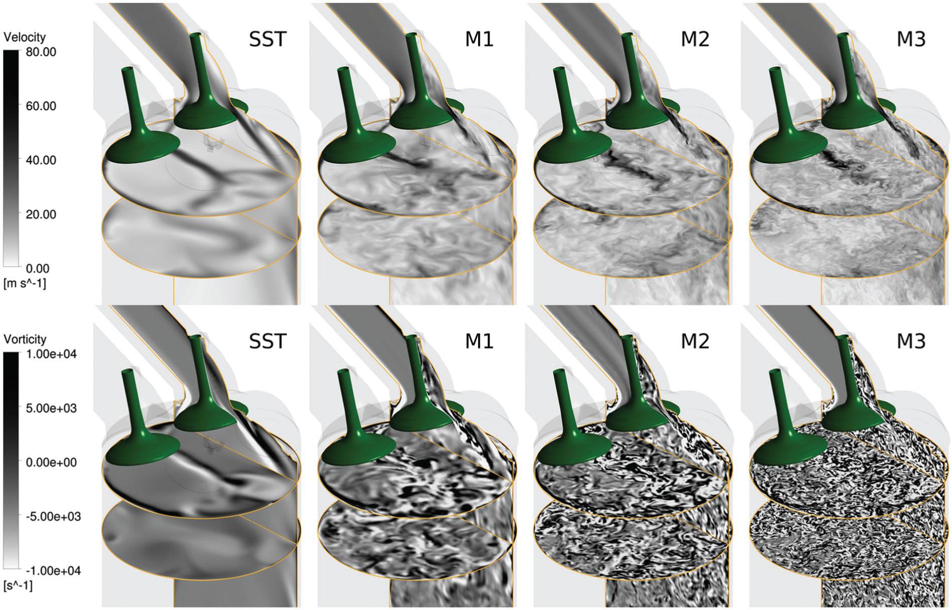
Comparison of the resolved velocity (top row) and vorticity (bottom row) visualized in two horizontal slices and one vertical (mid-valve) slice. From left to right, URANS (SST) and instantaneous snapshots are shown for the scale-resolving simulation on three different grids M1–M3.
Figure 8 shows the comparison between M1 and M2 using the SST-RANS model. No significant differences for the velocity (top) and the vorticity field can be identified. This is expected since as soon as the integral scales are resolved on the grid (already achieved for M1), further grid refinement should lead to negligible differences. A grid convergence of this type cannot exist in LES since the modeling and the numerics are strongly intertwined, for example, the local filter size is assumed to be proportional to the local grid size and directly influences the turbulent viscosity.
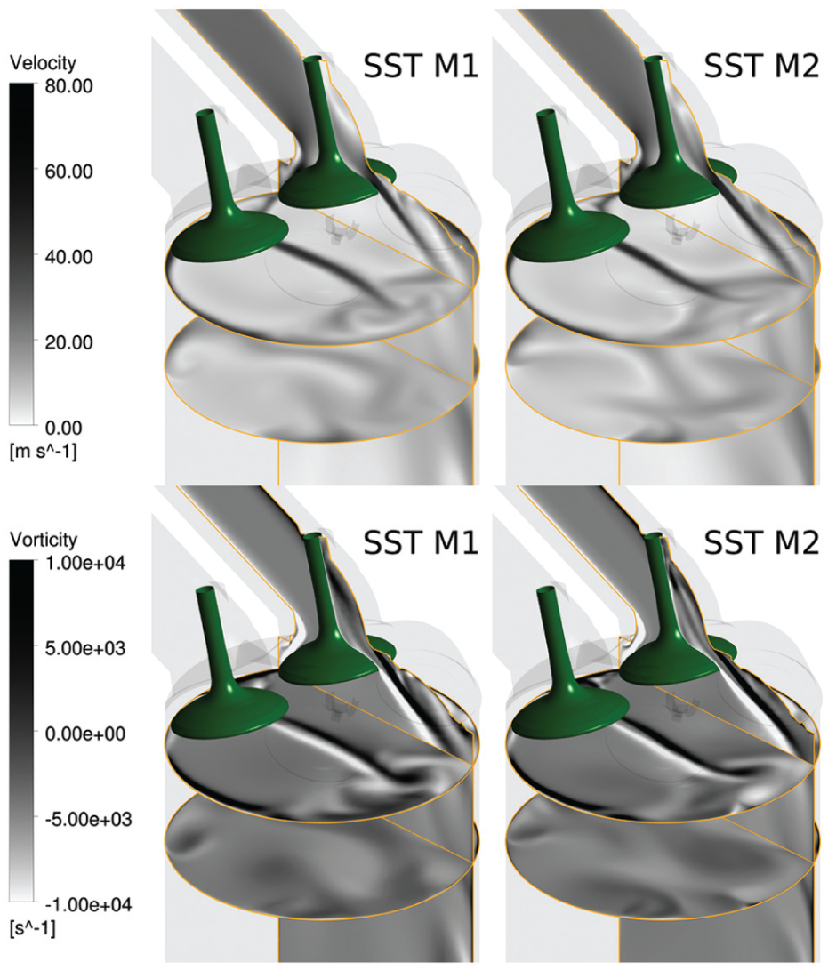
Comparison of the velocity (top row) and vorticity (bottom row) visualized in two horizontal slices and one vertical (mid-valve) slice using the SST URANS model with grids M1 (left) and M2 (right).
A side-by-side comparison of instantaneous snapshots is useful to assess the achieved resolution, but it does not allow a quantitative comparison with the experimental results. The time-averaged velocity fields in the vicinity of the valve are shown in Figure 9. In the upper row, the two URANS approaches are shown, while in the lower row, the SRS can be seen on the left. Experimental PIV data are on the right-hand side. A comparison of the experimental and the DES results on grids M2 and M3 (not shown here) yields very good agreement. The orientation of the intake jet is of particular importance: it is responsible for the formation of the large-scale tumble structure. It is interesting to note that the two URANS-based models show significant differences, which would lead to different charge motions in full engine calculations. This difference will affect the whole cause-and-effect chain through the tumble breakdown and the generation of the small-scale turbulent motion, initial flame kernel development and transition to turbulent combustion, respectively. Although the SST velocity field is closer to the scale-resolving results and especially the PIV results, the jet breakup is not captured, and thus, the penetration depth is overestimated. Only the SRS comes close to the experimental data. This finding is consistent with the instantaneous snapshots in Figure 7, which clearly show an earlier breakup for the SRSs on grids M1–M3.
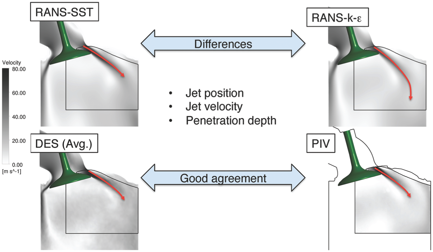
Comparison of the intake jet velocity for the URANS SST (upper left) and the URANS-k–ε (upper right) model. The time-averaged SRS data (lower left) and the experimental PIV data (lower right) are also shown. The experimentally accessible region is marked by a black line.
It must be noted that such PIV measurements are usually not available so close to the intake valve. However, based on the results presented, SRSs can be used as a reference dataset. Using very high resolutions as a “numerical experiment” can become a particularly good alternative for model development and evaluation. Consistent with Figure 4, this could even replace the experiment in step 3 of Figure 5 for certain applications.
From these results, it is obvious that SRSs offer a substantial benefit for combustion process development. Looking specifically at the example here, the SRS results match the experimental data, whereas both URANS approaches yield unsatisfactory results, and even more importantly, their predicted jet structures are significantly different. Either the highly resolved simulations or the PIV experiments are a valuable dataset for future model development on the process level, see steps 4–6 in Figure 5. Since the same cylinder head is used as in the transparent engine, the resulting transfer to the system level, steps 1 and 7, is straightforward.
Summary and outlook
The increasing availability of HPC resources offers the potential of using SRSs not only for academic research but also for engine combustion process development. For the latter, two major contributions of SRSs were identified in this work. First, highly resolved simulations allow us to analyze and understand the underlying physics and the complex interactions between the different processes along the cause-and-effect chain leading to CCVs of the combustion process. Second, SRSs can replace URANS approaches as an integral part of the design process, especially for operating points with significant CCV.
Based on an overview of the different modeling frameworks for engine simulations ranging from URANS to DNS, a gap in the current and future scope of industrial and academic research (with respect to SRSs) was identified. Academic research currently focuses on the general understanding of the individual processes such as spray or combustion fluctuations and their interactions. Using the highest possible resolution, especially for the fluid flow and mixing, means that the required modeling effort is reduced to a minimum since a significant portion of the vortex dynamics are resolved. However, some other processes which require modeling do not benefit directly from the high resolution, or the models are not even compatible with it since they were originally developed for URANS applications; one example is discussed for droplet evaporation.
In order to discuss the individual but strongly interacting phenomena and to break down the overall complexity of the engine combustion process, a cause-and-effect chain was proposed. A discussion of previous SRSs with respect to the individual contributions along the chain was used to emphasize the need for a systematic approach to model evaluation, development and validation, with the eventual aim of simulating a full engine. This proposed approach consisting of seven steps builds upon a previously suggested model development hierarchy but is specifically adapted for engine combustion. Starting from thermodynamic and optical engines on the system level, different topics are identified on the process level, which is less dependent on the specific engine and thus allow the physics to be investigated in an isolated but engine-relevant setting. Typical examples are high-pressure injections in constant-volume chambers or the intake flow on a test bench. Combining highly resolved simulation data—sometimes even including DNS—and experiments provides a framework for iterative a priori model evaluation and a posteriori model validation. Specifically for engines, the models should be developed such that they are able to work on different resolution levels ranging from LES to VLES and sometimes even URANS. The corresponding modeling depth changes significantly and URANS cannot be expected to deliver the same answer as a highly resolved LES, but it should be ensured that the best result is obtained within the given limitations. Finally, these models are then combined and used for simulations of the same engines investigated initially, which closes the loop on the system level.
An example of this kind of a highly resolved simulation, specifically looking at the effect of resolution and its effect on the velocity field, was shown for a process-design-relevant case, namely, the flow through an intake port of a modern gasoline engine. The impact of modeling on the resolved dynamics such as jet breakup and flapping was shown clearly, highlighting the benefit of a SRS compared to URANS.
The next steps should be to implement the proposed workflow outlined in this work in a single investigation; this can be achieved in close collaboration between industry and academia. In fact, the proposed approach allows models to be developed on the process level, for example, in the ECN network, but the benefit of the collaboration is to finally connect these investigations to the system level. This will effectively close the previously identified gap.
Footnotes
Acknowledgements
This article benefitted from fruitful discussions with Steffen Salenbauch, Stefan Buhl and Dirk Linse (BMW). The simulation results shown in section “Example of how SRSs can support both model and process development” were provided by Frank Hartmann and Stefan Buhl.
Declaration of conflicting interests
The author(s) declared no potential conflicts of interest with respect to the research, authorship and/or publication of this article.
Funding
This work was financially supported by the Saxon Ministry of Science and Fine Arts, the SAB (Sächsische Aufbaubank) and the European Union in the project “DynMo” (project number 100113147), as well as the FVV in the project “BSZII” (project number 6011333). The simulations were performed on the national supercomputer Cray XC40 at the High Performance Computing Center Stuttgart (HLRS) under the grant number ICECCV/44054.