
Abstract
Bio-inspired, hierarchical structures following the example of natural composites such as bone, wood or bamboo promise a new approach to advanced composites. This work focuses on hierarchical composites based around pultruded carbon fibre-epoxy rods, rather than layered plies of material. A structural member, or strut, of circular cross-section, consisting of cured pultruded rods and epoxy resin, demonstrates this hierarchical concept. This paper focuses on manufacturing of struts by vacuum infusion and by pressurised resin transfer moulding, with the aim of minimising porosity while retaining the desired cross-section. Rod alignment and packing are also considered. Vacuum infusion is carried out with stiff and flexible tooling, and pressurised resin transfer moulding using rigid cylindrical copper tools with and without a flexible liner. Porosity is measured via X-ray computed tomography. The results indicate a way forward for manufacturing low porosity hierarchical composites based on pultruded rods, either via vacuum infusion with a flexible tool, requiring machining to reach a circular cross-section, or pressurised resin transfer moulding using a combination of rigid tool and flexible liner at 3 x 10⁵ Pa or higher, where porosity is below the limit of detection in a Nikon XTH-320 CT scanner.
Introduction
Inspired by natural composites such as bamboo 1 or bone 2 (Figure 1), the Next Generation Fibre-Reinforced Composites (NextCOMP) programme 3 seeks to improve compressive performance through a novel, hierarchical approach to advanced composites. Typical fibre-reinforced composite structures do not reach the full potential of carbon fibre performance under compression. 4 By contrast, natural materials use hierarchical structures to achieve performance beyond that expected of the constituent materials. 5
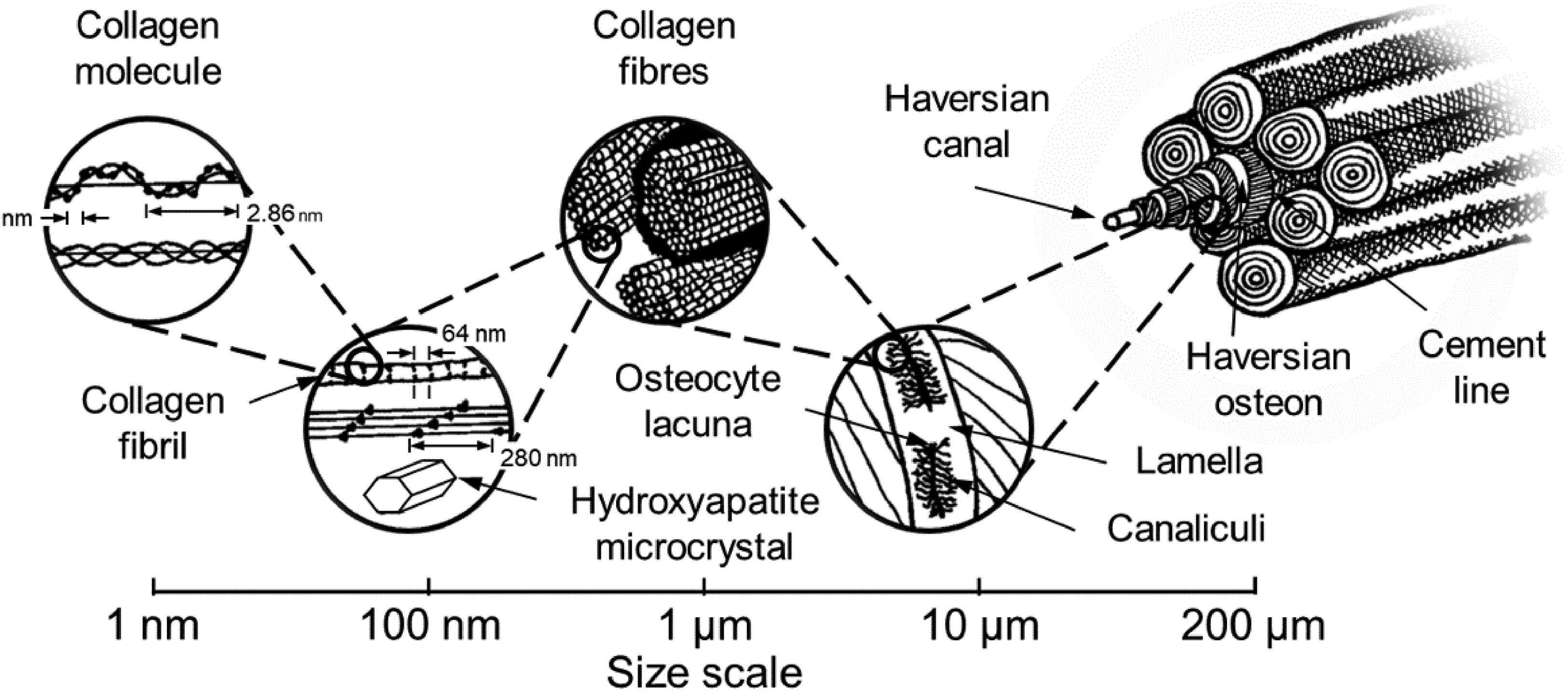
Illustration of hierarchical structure of bone. Adapted from Ref. 2
‘Hierarchy of structure’ is considered a key characteristic of biological systems 6 with each scale level conferring useful properties. Nepal et al. 7 discuss numerous examples demonstrating the widescale use of hierarchical structures in nature and the principles of hierarchical interaction across length scales. Cortical bone has been shown to be stronger in compression than in tension, 8 oat stems show features building hierarchically from the molecules of the cell wall upwards which Gangwar et al. have implemented into a multiscale model. 9 In equine hooves stiff tubules serve as reinforcements which support the structure under compression. 10
Features designed to improve compressive performance are introduced at multiple length scales. Novel fibres 11 and resins 12 are under development, along with new approaches at the ply level. 13 These hierarchical composites present different manufacturing challenges than traditional fibre-reinforced composites. 14
Pultruded rods are here used as elements within a larger three dimensional structure (Figure 2). These rod-based composites provide a meso-scale architectural layout that differs from traditional ply based composites 15 and as such offers new possibilities. Pultruded rods have been seen to achieve average failure load in compression 60% higher than equivalent prepreg systems by comparing data from tests of 0.7 mm diameter rods to manufacturer's data for prepreg, 16 though good fibre alignment and spacing in the pultruded rod is crucial. 17
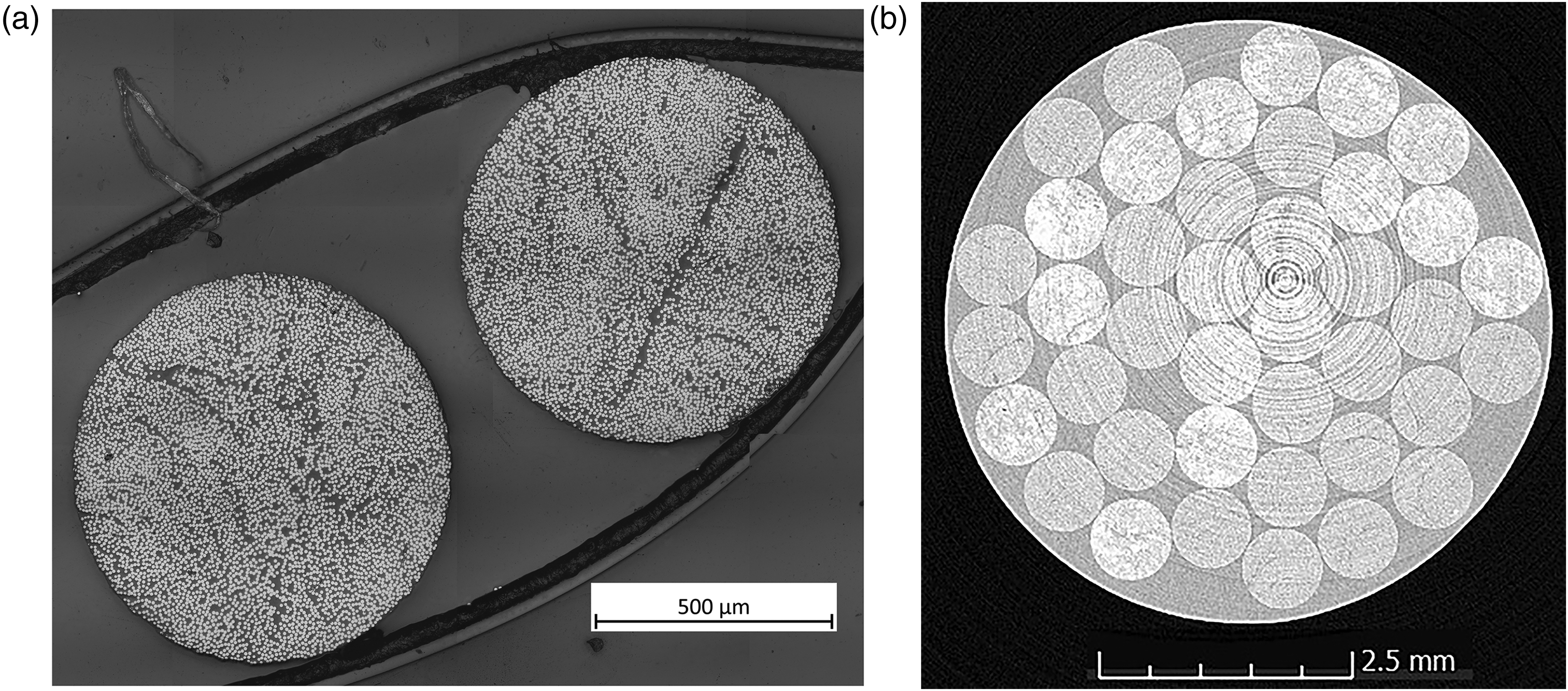
Hierarchical composite concept. (a) Cross-section of two pultruded rods inside sample clip taken using Zeiss microscope 20× lens, mosaic image with z-stacking. (b) Cross-section of cylindrical strut rod-based composite, slice from X-ray computed tomography reconstruction of strut taken using Nikon XTH-320.
Use of these rods as discrete building blocks provides the option to add further features to control compressive failure such as overbraiding of each rod. 18 Use of two resin systems, one within the rods and another surrounding them, also expands the design space to tailor the properties to improve compressive performance. The resin areas between the rods may be utilised to provide shear support such as through fuzzy carbon overbraids, 19 or could perhaps be tailored to suppress kink band formation using a more compliant material between the carbon fibre-epoxy rods, similar to the novel bio-inspired structure demonstrated for modified traditional ply-type systems, under the NextCOMP project, by Garulli et al. 13 Ritchie 20 discusses strength and toughness using the hierarchical structure of bone as an example. Combining stiff pultruded rods with a tougher matrix may allow a similar combination to be made utilising the performance of carbon fibre. 21 Rods of varying cross-section may, if placement can be controlled, be used to deliver a functional gradient effect similar to that seen in plant stems. 22 For any of these possibilities to be realised, a reliable manufacturing method must be developed.
Cylindrical structural members (struts) were chosen for a manufacturability trial of the hierarchical composite concept. The circular cross-section allows maximisation of the volume scanned for a given resolution during X-ray computed tomography (XCT) and is a geometry suitable for use in applications such as geodesic domes. The struts consist of carbon fibre-epoxy pultruded rods of circular cross-section, plus a second epoxy resin phase surrounding the rods. These hierarchical composites must be manufactured with minimal porosity. The pultruded rods 23 are flexible with diameter 0.7 to 0.8 mm having a minimum radius of curvature of order 10 cm before damage occurs. Therefore the rods may deform and/or move during manufacture if insufficiently constrained. This is undesirable as rod movement during manufacture may result in misalignment.
Clarke 15 manufactured a similar strut concept using Graphlite rods, which are no longer available, and Ciba-Geigy MY750 epoxy resin with a triethylene tetramine HY951 hardener. A rigid glass tubular tool of internal diameter 12.36 mm was used and the infusion carried out under vacuum, with both the de-gassed resin/hardener mix and the tool heated to 60 °C. The published image of a failure surface showed a strut of circular cross-section with tightly packed rods.
Potter et al.24,25 applied the same manufacturing method, 15 using the same materials to produce hierarchical struts. Following Wisnom's 26 concept of using an overwind to radially compress the struts and thus suppress transverse splitting, Potter et al.24,25 overwound some of the struts with aramid fibre. The struts were subjected to compression after impact tests, carried out with a square section impactor which passed through a square guide tube perpendicular to the strut to ensure alignment. 25 The overwound struts demonstrated an improvement in performance ranging from 25% increase in ultimate compressive strength for unimpacted samples to over 200% increase in ultimate compressive strength for samples impacted at 40 J.
Successful demonstration of repeatable manufacturability of these struts will open up the opportunity to manufacture and test hierarchical struts with overbraids of component rods and/or overbraiding/overwinding of the entire strut. 19
The aim of the manufacturability trials reported here is to produce rod-based struts of circular cross-section with the lowest achievable porosity and without large resin rich areas. A smaller cross-section is preferred to minimise the volume of material necessary for testing multiple samples, with 6 mm diameter considered the smallest value likely to give a representative result for a multiple rod strut during future mechanical testing. Larger diameter struts are manufactured during initial manufacturability trials for ease of handling before moving to the 6 mm diameter case. As the pultruded rods have diameter 0.8 mm, a 6-mm strut allows up to seven plain rods to fit across the strut diameter, depending on packing. One central rod could in theory be surrounded by three concentric rings of rods. A minimum of two such rings would ensure that there is a ring of rods surrounded on all sides by other rods – that is not in the centre or on the outer edge. As perfect packing cannot be guaranteed at this stage, and to allow space to add other elements to the hierarchical structure at a later date as discussed above, the 6 mm diameter case was chosen.
Pressurised resin transfer moulding is expected to result in lower porosity than vacuum infusion due to the higher pressure. Vacuum infusion is however a more accessible manufacturing method, available to organisations which do not have access to pressurised systems, therefore both options are investigated here and the results compared.
Materials and methods
Experimental approach
A sequential approach is used, where each result informs the next test case. While a 6-mm diameter strut is the goal, trials began with larger struts as used by Clarke 15 and Potter,24,25 investigating different manufacturing options before moving to the smaller diameter.
Vacuum infusion using a solid tool is the method used by Clarke 15 and Potter,24,25 but the porosity of the struts produced in these previous works have not been characterised. This is therefore a logical starting point. A flexible tool option was trialled in attempt to decrease the porosity and increase the rod volume fraction. The reinforced flexible tool was then trialled to investigate the possibility of a balance between the advantages of a flexible tool and the loss of cross-sectional control.
Pressurised resin transfer moulding is then carried out, beginning at a relatively low pressure and increasing this to characterise the effect of the increased pressure on not only porosity but void geometry in this hierarchical system. Trials at an 8-mm diameter resulted in difficulty demoulding which damaged the strut, hence the addition of a flexible silicone liner, which was used in the final trials of 6 mm diameter struts, with and without pre-wetting of the rods with resin.
Materials
Commercially available pultruded rods, 23 consisting of unidirectional carbon fibre and an epoxy matrix with Tg onset of 80 °C, of circular cross-section 0.8 mm in diameter were cut to lengths of 500 mm.
Vacuum infusion was carried out using Prime 27 resin 27 with Prime slow hardener. 28 This was chosen following good results for infusion during previous work with a different, non-hierarchical composite architecture. 29 The Prime 27 resin and Prime slow hardener system was not optimised for pressurised resin transfer moulding due to the limited pot life, with the resin viscosity increasing notably during the time taken to pressurise the system, therefore resin RS-M135 30 and hardener RS-MH137 31 were used for the pressurised RTM trials.
Vacuum infusion
Struts were manufactured by vacuum infusion, using a resin which is liquid at room temperature, in contrast to reported work with a heated resin.
24
Trials were carried out with three test configurations as follows:
tubular tools of rigid borosilicate glass, 12.5 mm diameter, no vacuum bag tubular tools of unreinforced flexible silicone, 12 mm diameter, vacuum bag external to tool to provide radial compression tubular tools of flexible silicone with a spiral metallic reinforcement, 12.5 mm diameter, vacuum bag external to tool to provide radial compression
Each tool was internally coated with two layers of release agent and rods were manually inserted into the tool. For consistency, release agent was used with all test configurations.
For ease of manufacture and demoulding, 12 to 12.5 mm diameter struts were trialled.
The tubular tool was suspended vertically with the resin inlet at the base and outlet at the top of the tube, to allow bubbles to rise to the surface. The tool was connected top and bottom to silicone hose using bagging tape, and the configuration tested prior to manufacturing trials to ensure the seals were secure without leaks. For the flexible tool cases the tool was surrounded by a vacuum bag providing external radial pressure.
Prime 27 resin 27 with Prime slow hardener 28 was measured according to the manufacturer's guidelines with a 25 g resin:7 g hardener ratio. The mix was carefully stirred and de-gassed for 30 minutes prior to infusion. The speed of the infusion was controlled using clamps on the inlet tube, with flow restricted at the start of the process and gradually opened to allow full flow. After infusion the strut was cured in an oven at 80° C for four hours.
Pressurised resin transfer moulding
A rigid copper tube tool, in some cases with the addition of an internal flexible silicone liner, was used with a CIJECT® resin injection system to manufacture struts. The resin system used is liquid at room temperature so heating was not required. The tool or liner was again internally coated with release agent. Rods were manually inserted into the tool or liner. In order to ascertain whether or not pre-wetting of the rods affects porosity, trials included an option with rods dipped into resin before insertion.
Resin RS-M135 30 was combined with hardener RS-MH137 31 and de-gassed for 30 minutes before injection.
The tubular tool was held vertically with inlet at the lowest point and outlet at the highest to allow bubbles to rise to the surface. Resin injection began at 1 × 10⁴ Pa and was slowly increased to the maximum value for each trial (Table 1). When the highest pressure was reached, the outlet was momentarily closed to force bubbles to the top before re-opening and allowing the bubbles to exit the tool. A representation of this process is shown in Figure 3.
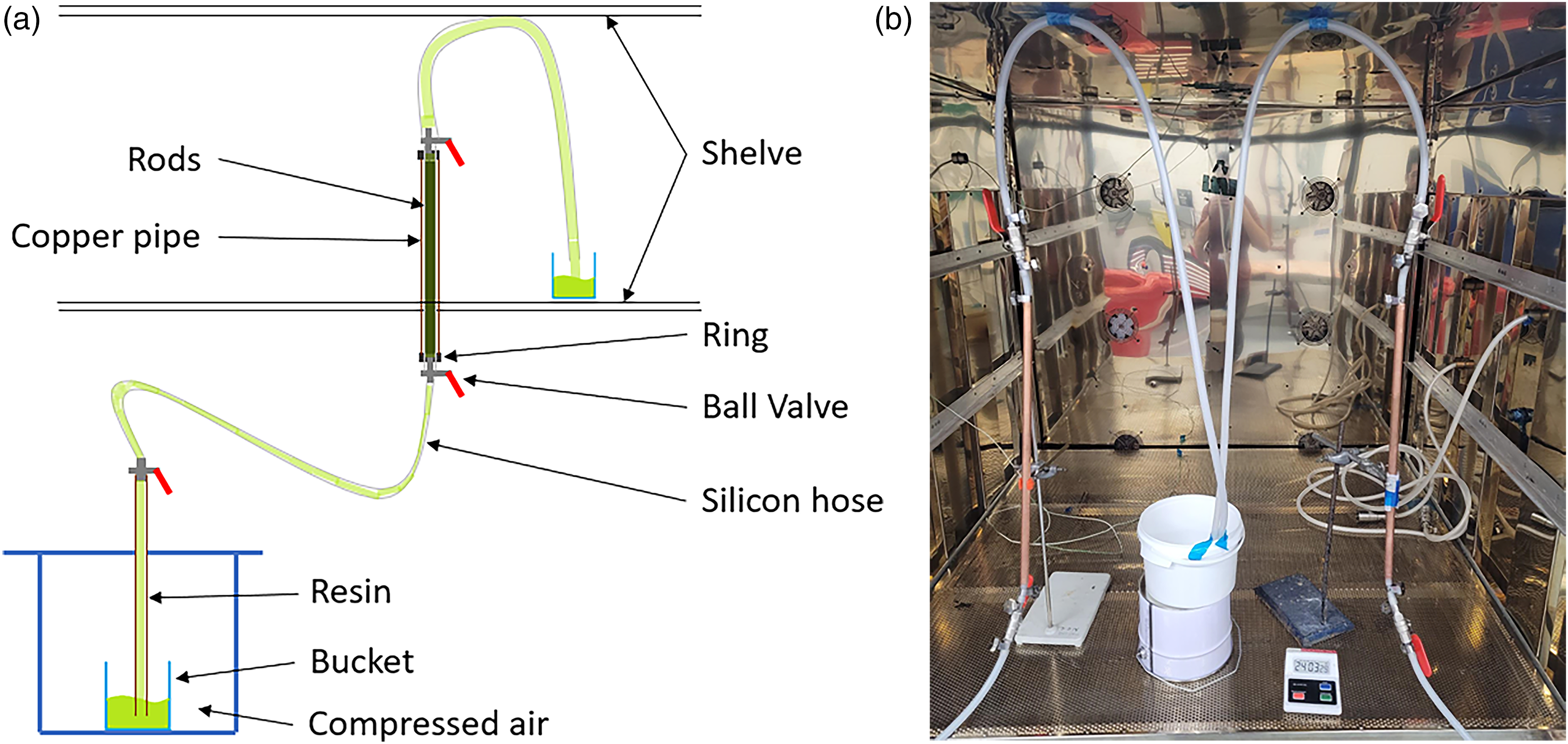
(a) Diagram final setup for resin transfer moulding approach with rods fitted into a liner and a copper pipe tube and (b) picture of the manufacture of struts during injection of resin.
Summary of results with RTM referring to resin transfer moulding.
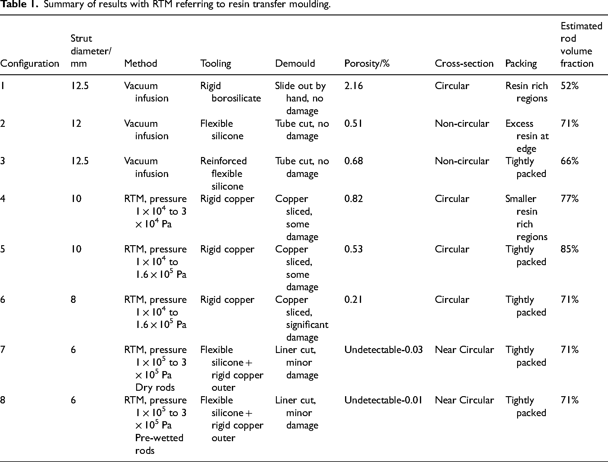
The following configurations were tested:
4. tubular tools of rigid copper, maximum pressure 3 × 10⁴ Pa, 10 mm diameter 5. tubular tools of rigid copper, maximum pressure 1.6 × 10⁵ Pa, 10 mm diameter 6. tubular tools of rigid copper, maximum pressure 1.6 × 10⁵ Pa, 8 mm diameter 7. tubular tools of rigid copper with flexible silicone liner, maximum pressure 3 × 10⁵ Pa 8. tubular tools of rigid copper with flexible silicone liner, maximum pressure 3 × 10⁵ Pa with pre-wetted rods
The strut was then cured in an oven at 50 °C for 10 h.
Porosity analysis
Cured struts were sectioned and inspected by microscopy and X-Ray Computed Tomography (XCT). XCT imaging of samples from struts was performed using a Nikon XTH-320 with reflection head and flat panel detector, no filtration, set to 80 keV and 124 µA with 4 frames per projection, exposure 708 ms and 3141 projections per scan. Resolution was the best achievable for each sample diameter, ranging from 7.1 to 9.2 µm. Scans were reconstructed using CT Pro 3D version 6.8.7977.22560 software from Nikon metrology, with no filters and automatic beam hardening corrections.
Porosity analysis of XCT reconstructions was carried out using the volume graphics (VG) Studio Max version 3.4 post-processing tool using the largest feasible region of interest. The region of interest is defined using built in geometry tools to select part of the volume. The selection must be wholly inside the strut as selection of a region containing external air will lead to a falsely high reading. The largest feasible region of interest is therefore slightly smaller than the volume scanned.
Thresholding using the built in ISO-50% surface determination routine was used to determine the boundary between material and background, following which porosity was measured with a minimum size of 3 voxels up to an unrealistically high maximum of 100 mm3, ensuring all detectable voids were listed.
For a small subset of results this method was checked against an in-house algorithm analysing slices from the same XCT scan based on greyscale values, manually verified using ImageJ. The VG studio method is more computationally efficient and can be used to generate visualisations so is preferred for processing of results, verification was considered prudent as this is a commercial piece of software so exact details of the algorithm used are not available. The two methods delivered results that were consistent within error therefore the more efficient VG studio method was used going forward.
Rod volume fraction is estimated using XCT scan imagery, based on a circular cross-section with the stated diameter. For configurations 2 and 3 the cross-section is not circular so this should be considered an approximation only.
Results
Observations of vacuum infused struts
Configuration 1, the rigid tool, has a low rod volume fraction compared to the other results, leading to large resin rich areas as seen in Figure 4(a). While the rods were packed into the rigid tool prior to infusion, movement during infusion and cure was sufficient to result in this non-uniform rod density. This result provides a baseline from which to improve. The rod volume fraction of 52% suggests that tighter packing should be feasible, though difficult to achieve with the rigid tool due to flexing of the rods.
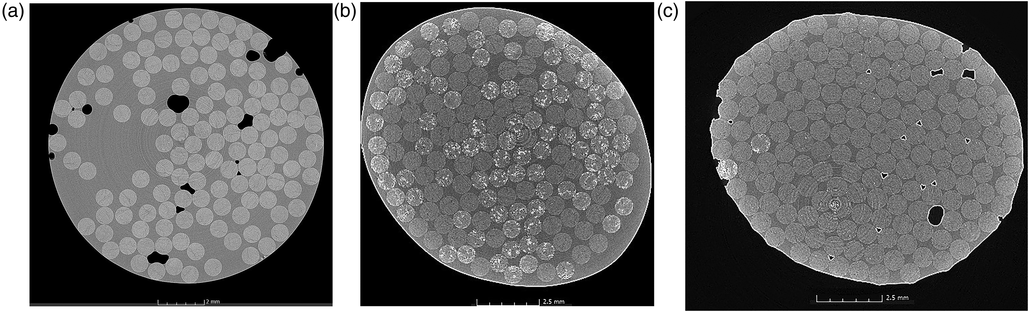
Cross-section slices of X-ray CT reconstructions of: (a) configuration 1, rigid tool strut; (b) configuration 2, flexible tool strut; and (c) configuration 3, reinforced flexible tool strut; manufactured by vacuum infusion.
Due to the transparent nature of the rigid tool, race-tracking between the rods and internal tool surface was clearly visible. Slowing the infusion by restricting the inlet tube was unsuccessful in preventing this. Following cure, XCT scans (Figure 4(a), Figure 6) showed that voids were present throughout including some large voids between tightly packed rods thought to be due to internal race-tracking.
Configuration 2, the flexible tool, delivered a marked improvement in rod volume fraction, reaching 71%, and significant reduction in porosity to 0.51% (Figure 4(b)), including a complete lack of the large resin free zones between rods seen in configuration 1, characteristic of race-tracking at the outer edge. The presence of the outer vacuum bag made visual checks for race-tracking impossible.
However, the flexibility of the tool results in a strut cross-section which is not circular (Figure 4(b)).
The configuration 1 (rigid tool) strut with the lowest porosity (Figure 4) had a void fraction of 2.2 ± 1.1% according to the in-house algorithm, which agrees with the VG studio figure of 2.16%. A typical configuration 2 (flexible tool) strut sample had void fraction 0.6 ± 0.1% according to the in-house algorithm, again in agreement with the VG studio figure of 0.51%.
This shows a reduction in porosity of 76%.
Configuration 3, the flexible tool with wire reinforcement, resulted in well packed samples with porosity slightly higher (0.68%) than those manufactured using a flexible tool without reinforcement. There is no resin rich area on the edge as seen for configuration 2, but voids are clearly visible between rods and the cross-section has distorted (Figure 4(c)), therefore this offers no improvement over configuration 2.
Observations of pressurised RTM struts
Configuration 4 struts, injected at pressure of 3 × 10⁴ Pa, showed higher porosity (0.82%) (Figure 5) than configuration 2 and 3 struts (Figure 4) manufactured by vacuum infusion with flexible and reinforced flexible tooling, despite a higher rod volume fraction. The vacuum pumps used for the vacuum infusion trials can achieve a pull of −1 × 10⁵ Pa, which may explain this.
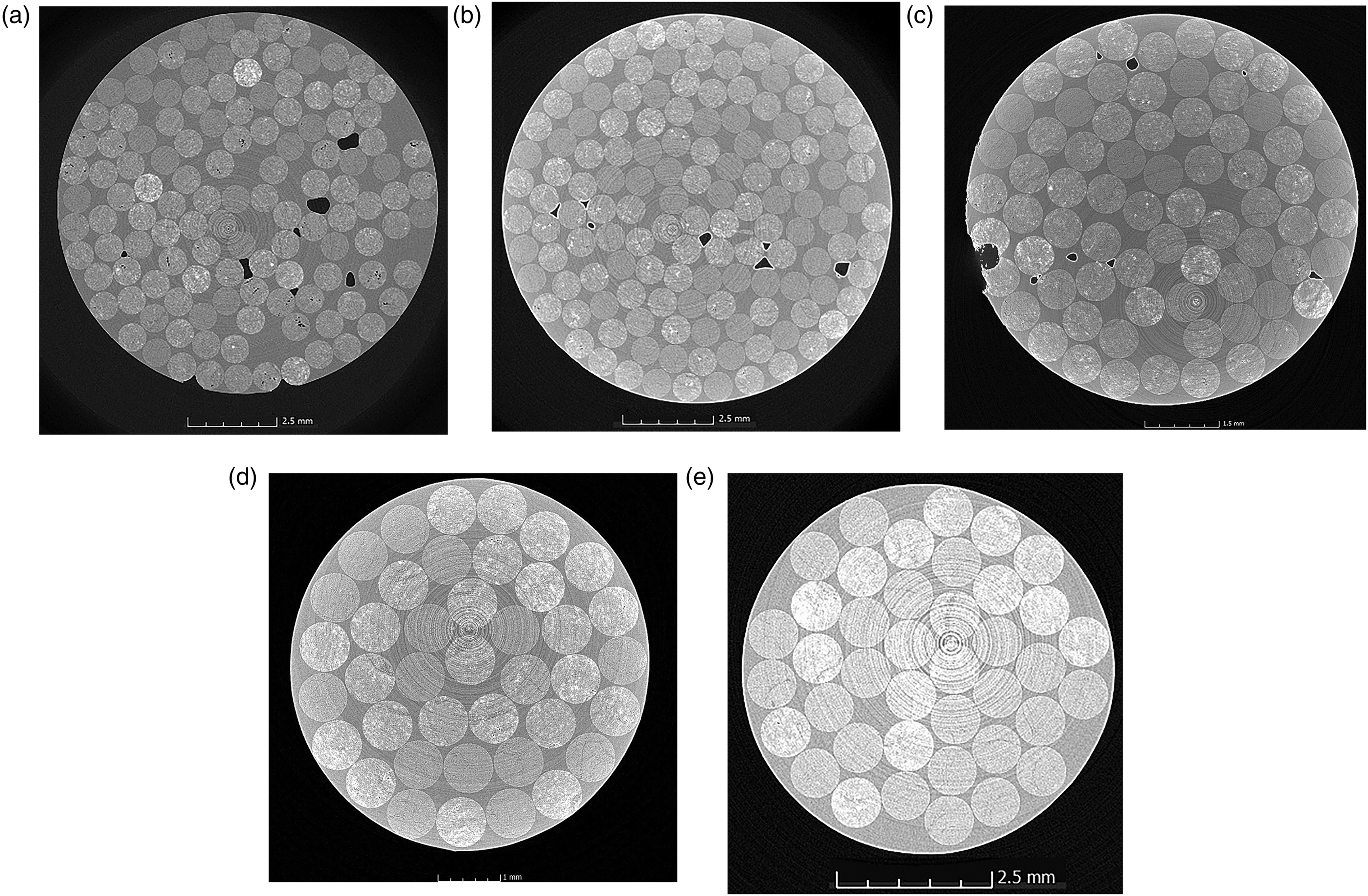
Cross-section slices of X-ray CT reconstructions of struts manufactured by pressurised resin transfer moulding. (a) Configuration 4 rigid copper tool, max pressure 3 × 10⁴ Pa. (b) Configuration 5 rigid copper tool, max pressure 1.6 × 10⁵ Pa. (c) Configuration 6 rigid copper tool, 8 mm diameter, max pressure 1.6 × 10⁵ Pa. (d) Configuration 7 copper tool with flexible liner, 6 mm diameter, max pressure 3 × 10⁵ Pa, dry rods. (e) Configuration 8 copper tool with flexible liner, 6 mm diameter, max pressure 3 × 10⁵ Pa, pre-wetted rods.
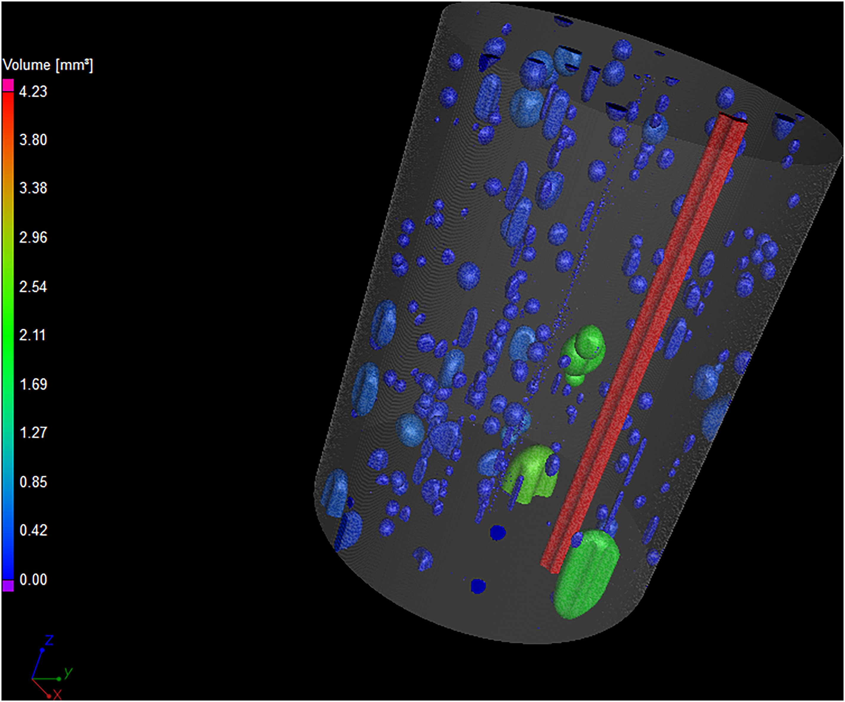
Visualisation of voids in strut manufactured by configuration 1 vacuum infusion in a rigid tool, coloured by void volume. Porosity is 2.16%. The largest void runs the length of the scanned sample between rods and is due to race-tracking. Bubbles in the resin are also visible.
For configuration 5 the maximum pressure was increased to 1.6 × 10⁵ Pa, resulting in similar porosity to that achieved using configuration 2, vacuum infusion with a flexible tool – 0.53% and 0.51%, respectively – with the advantage of keeping the circular cross-section.
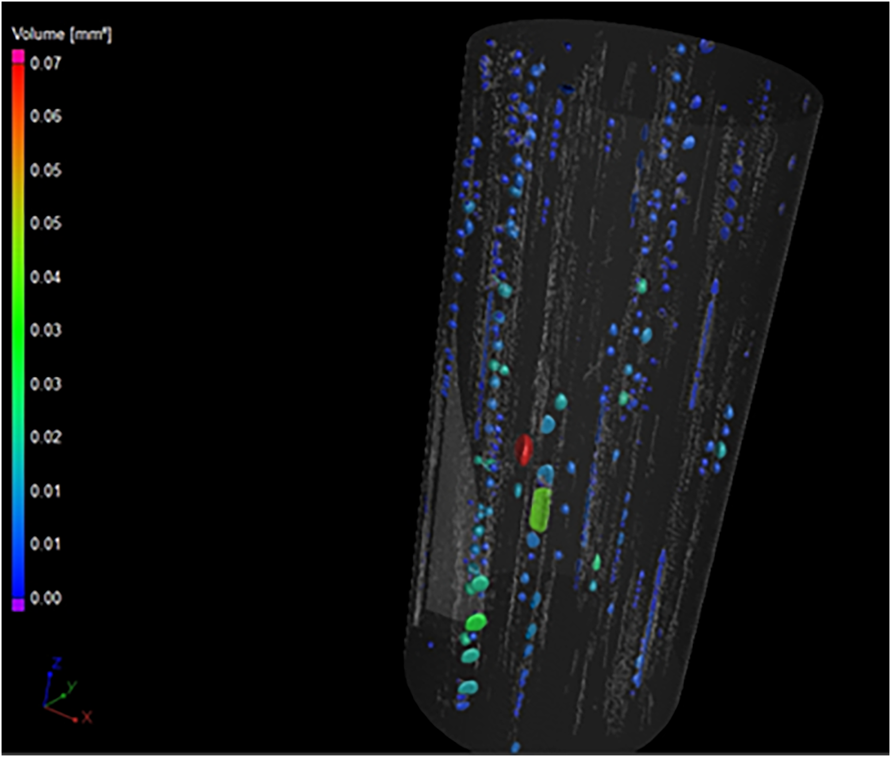
Configuration 6 kept the same approach and pressure as configuration 5, but reduced strut diameter. This resulted in a distinct decrease in porosity, from 0.53% to 0.21%, despite a decrease in rod volume fraction from 85% to 71%. The decrease in rod volume fraction equates to an increase in resin volume fraction, and the voids measured in the porosity analysis occur in the resin. Changes in diameter are reasonably expected to result in different rod volume fractions due to packing considerations and practicality of manufacture using smaller tooling. Figure 7 shows a three dimensional representation of the voids from a configuration 5 sample. The voids are elongated and flattened between tightly packed sections of rods. Unlike the long continuous voids caused by race-tracking in configuration 1, these are discontinuous in nature and have the appearance of flattened bubbles. Figure 8 shows a three-dimensional representation of the voids from a configuration 6 sample. Here the rods are slightly less tightly packed and fewer flattened voids are seen, with smaller rounded bubbles being evident.
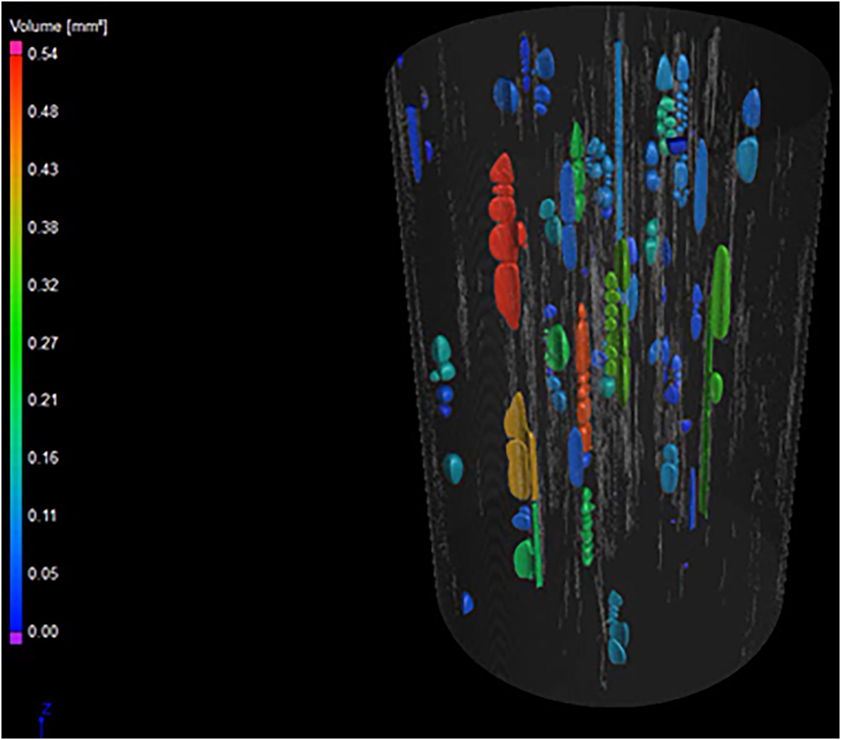
Visualisation of voids in 10 mm diameter strut manufactured by configuration 5 pressurised resin injection at maximum pressure 1.6 × 10⁵ Pa using a rigid tool, coloured by void volume. Porosity is 0.53% Flattened voids between rods can be observed.
Visualisation of voids in 8 mm diameter strut manufactured by configuration 7 pressurised resin injection at maximum pressure 1.6 × 10⁵ Pa using a rigid tool, coloured by void volume. Porosity is 0.21% excluding the damage which occurred during demoulding, visible as a grey region extending into the strut. Fewer flattened voids between rods are visible here, with more rounded ‘bubble’ geometry voids seen.
Configuration 4, 5 and 6 struts manufactured using resin transfer moulding without a liner kept their circular cross-sections (Figure 5).
The liner was introduced in response to difficulties de-moulding the struts, where the need to slice the copper sleeve away resulted in machining damage to the outer surface. Use of the liner with a rigid copper outer layer resulted in only slight deviations from a truly circular cross-section as can be seen for configurations 7 and 8 (Figure 5).
Using the flexible liner, configuration 7 reduced the diameter to the target 6 mm. With a pressure of 3 × 10⁵ Pa, porosity dropped to mostly undetectable levels. Figure 9 shows the only instance of a measurable void found in samples manufactured using configuration 7.
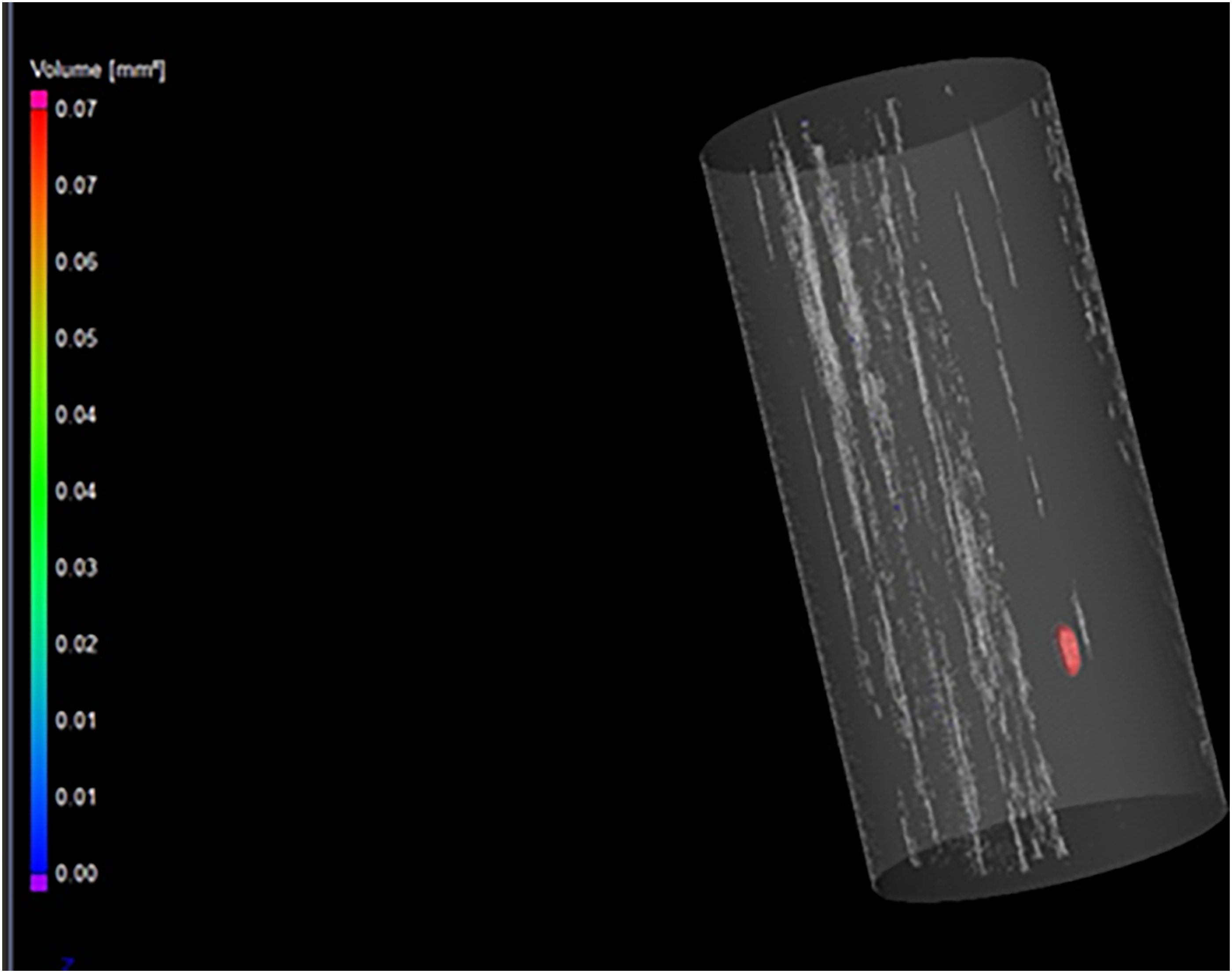
Visualisation of void in strut manufactured by pressurised resin injection at maximum pressure 3 × 10⁵ Pa using a rigid tool, coloured by void volume. Porosity is 0.03%. One bubble can be seen. Other samples manufactured by this method had no visible bubbles. Light grey areas are features within the individual rods, which did not meet the 3 voxel minimum required to detect a void.
Configuration 8 trialled pre-wetting the rods both to have a pre-injection setup with minimal air present and as preparation for making struts containing overbraided rods, where the braid may require pre-wetting. The resin formed a sticky coating on the rods which resulted in difficulties in manufacture, as a consequence a multi-part mould will be designed for future work.
Configurations 6, 7 and 8 all have rod volume fraction of 71%, which suggests that the reduction in porosity between configuration 6 and configurations 7 and 8 is due to the increase in pressure only.
Discussion
While employing pressurised resin transfer moulding delivered higher quality struts than using vacuum infusion, the 76% improvement made by use of a flexible tool and external pressure from a vacuum bag was significant.
The issue regarding loss of cross-section control in vacuum infusion of these hierarchical, rod-based struts therefore requires manufacturing of a larger strut than needed followed by machining to size. This extra processing step and wasted material is far from ideal, but allows that where pressurised resin transfer moulding is not available vacuum infusion may be a workable option, making hierarchical composites accessible to a wider range of manufacturers.
Between configurations 1 and 2 (rigid tool and flexible tool plus vacuum bag) the rod volume fraction has increased from 52% to 71%, partially due to the compression of the flexible tool leaving less room for excess resin and partially due to the flexibility of the tool making initial packing easier to achieve. This increase in rod volume fraction leaves less room for voids, however the tighter packing of the rods might at first glance give concern regarding likelihood of long voids between groups of rods caused by race-tracking, which is seen in the rigid tool configuration 1. That this race-tracking does not appear to occur with the flexible tool of configuration 2, but does occur with the reinforced flexible tool of configuration 3, which is more resistant to the radial compression from the vacuum bag, suggests this radial compression is crucial to achieving a good result with vacuum infusion. As the reinforced flexible tool offered no improvement in cross-section retention there is no advantage to it.
Given the hierarchical nature of the strut, voids between rods even at low total porosity are expected to reduce mechanical performance due to reduced rod-resin contact and the possibility of the flexible rods, without resin constraint, bending into the elongated void zones. Void geometry is therefore considered likely to be as important as the measured porosity. Elongated voids of a different nature to the race-tracking derived ‘dry zones’ seen in configuration 1, in this case appearing as bubbles flattened and extended in regions between rods, can be seen in pressurised RTM configuration 5, which has 85% rod volume fraction. Configuration 6, manufactured with the same pressure, has 71% rod volume fraction due to the change in diameter of the strut, and shows mostly smaller, bubble type voids, with lower porosity overall. This suggests that the optimum approach for minimising porosity may not be to maximise the packing of the rods. Furthermore, if the matrix surrounding the rods is used as a softer phase in a biomimetic manner, a lower rod density may be needed. 32 While configurations 7 and 8 showed porosity dropping below the limit of detection using the CT scanner available, this should not be interpreted as meaning porosity is zero – smaller voids of less than the three voxel size required for detection may be present. It is therefore worth considering future study regarding optimal rod density for minimal porosity.
Following this successful demonstration of repeatable manufacturing of undetectable porosity rods, work is underway to develop a multi-part tool which is intended to solve the demoulding problem and allow the next generation of struts to be manufactured. Rod alignment and packing can be more precisely controlled when inserted into a tool which opens along the length. Furthermore, future work will require more complex architectures including addition of overbraids and/or other additional material to the rods and struts, following the hierarchical concept outlined earlier.
Conclusions
Manufacture of hierarchical composite structural members of small diameter (6–12 mm) involves numerous challenges, notably minimising porosity and ease of de-moulding. The most successful method was resin transfer moulding using a semi-flexible tube plus a rigid outer layer with a gradual increase of resin pressure to 3 × 10⁵ Pa, which resulted in porosity undetectable by the Nikon XTH X-ray CT scanner
Void geometry suggests that maximising rod volume fraction may not result in minimising porosity, with bubbles becoming trapped and elongated between tightly packed rods. Further optimisation of this may be required.
Where pressurised RTM is not available, vacuum infusion using a flexible tool with external pressure by way of a vacuum bag resulted in 76% reduction in porosity compared to use of a rigid tool. However, the cross-section was not circular, so it would be necessary to machine the strut down to achieve the desired cross-section.
Repeatable manufacture of hierarchical, pultruded rod-based composites with low porosity, acceptable cross-section and tightly packed rods has been demonstrated. This will now be used in developing the next iteration of hierarchical composites.
Footnotes
Acknowledgements
Figure 1 was drawn by our colleague David B Anthony and is used with his explicit permission.
Supporting data can be requested from the corresponding author but may be subject to confidentiality obligations. For the purpose of open access, the author has applied a Creative Commons Attribution (CC BY) license to any Author Accepted Manuscript version arising.
Declaration of conflicting interests
The authors declared no potential conflicts of interest with respect to the research, authorship and/or publication of this article.
Funding
The authors kindly acknowledge the funding for this research provided by UK Engineering and Physical Sciences Research Council (EPSRC) programme Grant EP/T011653/1, Next Generation Fibre-Reinforced Composites: a Full Scale Redesign for Compression in collaboration with Imperial College London.