
Abstract
Lightweight design by using low-density and load-adapted materials can reduce the weight of vehicles and the emissions generated during operation. However, the usage of different materials requires innovative joining technologies with increased versatility. In this investigation, the focus is on describing and characterising the failure behaviour of connections manufactured by an innovative thermomechanical joining process with adaptable auxiliary joining elements in single-lap tensile-shear tests. In order to analyse the failure development in detail, the specimens are investigated using in-situ computed tomography (in-situ CT). Here, the tensile-shear test is interrupted at points of interest and CT scans are conducted under load. In addition, the interrupted in-situ testing procedure is validated by comparing the loading behaviour with conventional continuous tensile-shear tests. The results of the in-situ investigations of joints with varying material combinations clearly describe the cause of failure, allowing conclusions towards an improved joint design.
Introduction
The current global challenges require emissions to be reduced in all sectors. 1 In the transport sector, emissions can be reduced, for example, by consistent lightweight design. 2 This can be achieved among others by replacing components previously made mainly of steel materials with generally lighter metallic but also non-metallic materials. 3 However, combining and joining the different materials poses new challenges for joining technology. Conventional joining processes, which are often characterised by a limited process control and flexibility, reach their limits. 4 For conventional, thermal joining processes such as laser welding, the different physical properties already pose a challenge. 5 Joining of non-metallic (such as fibre-reinforced plastics) and metallic materials is sometimes not possible. One solution to this challenge of joining dissimilar materials can be the use of mechanical joining processes. The mechanically manufactured joints often achieve a high joint strength due to the formation of a form fit as well as a force-fit and are potentially very versatile. 6 However, it is also evident that the versatility of conventional mechanical joining processes such as clinching is limited. For clinching, this can be explained by the fact that the materials to be joined must have a sufficiently high forming capacity, which is not always the case for cast aluminium alloys or fibre-reinforced plastics, for example. 7 This has motivated increasing efforts in recent years to improve the versatility of conventional joining processes 8 and to research new, highly versatile joining processes using adaptive joining elements 4 or overcoming insufficient forming capacity by adapted processes like hole hamming. 9 One example of achieving such a high degree of adaptability is the use of auxiliary joining elements that can be adapted precisely to the requirements (dimensions, material properties) of the joint. 10 The possibilities for producing joints with good properties from different material thickness combinations (e.g. aluminium and steel) by thermomechanically manufactured joints using adaptable auxiliary joining elements have already been demonstrated. 11
Joining with auxiliary elements
Based on these possibilities of using auxiliary joining elements, this publication presents results on a two-stage thermomechanical joining process. In the first process stage (Figure 1(a)), the auxiliary joining elements (Friction Spun Joint Connector (FSJC)) required for joining are produced from a round wire section by means of a thermomechanical forming process. The greatest advantage of this first process step is that a wide variety of FSJC, which are variable in both length and diameter, can be produced on a readily available and simple semi-finished product (such as the round wire section). At the beginning of this first process step, a round wire section is clamped in a horizontally arranged milling spindle from the manufacturer Weiss Spindeltechnologie GmbH (Maroldsweisach, Germany). The rotationally symmetrical shape of the FJSC is formed by a tungsten carbide tool based on a corresponding path movement in the thermomechanical forming process. During the process, frictional heat is generated based on the frictional contact between the forming tool and the workpiece, which leads to temperatures above T = 1000 °C for the processing of steel rods.
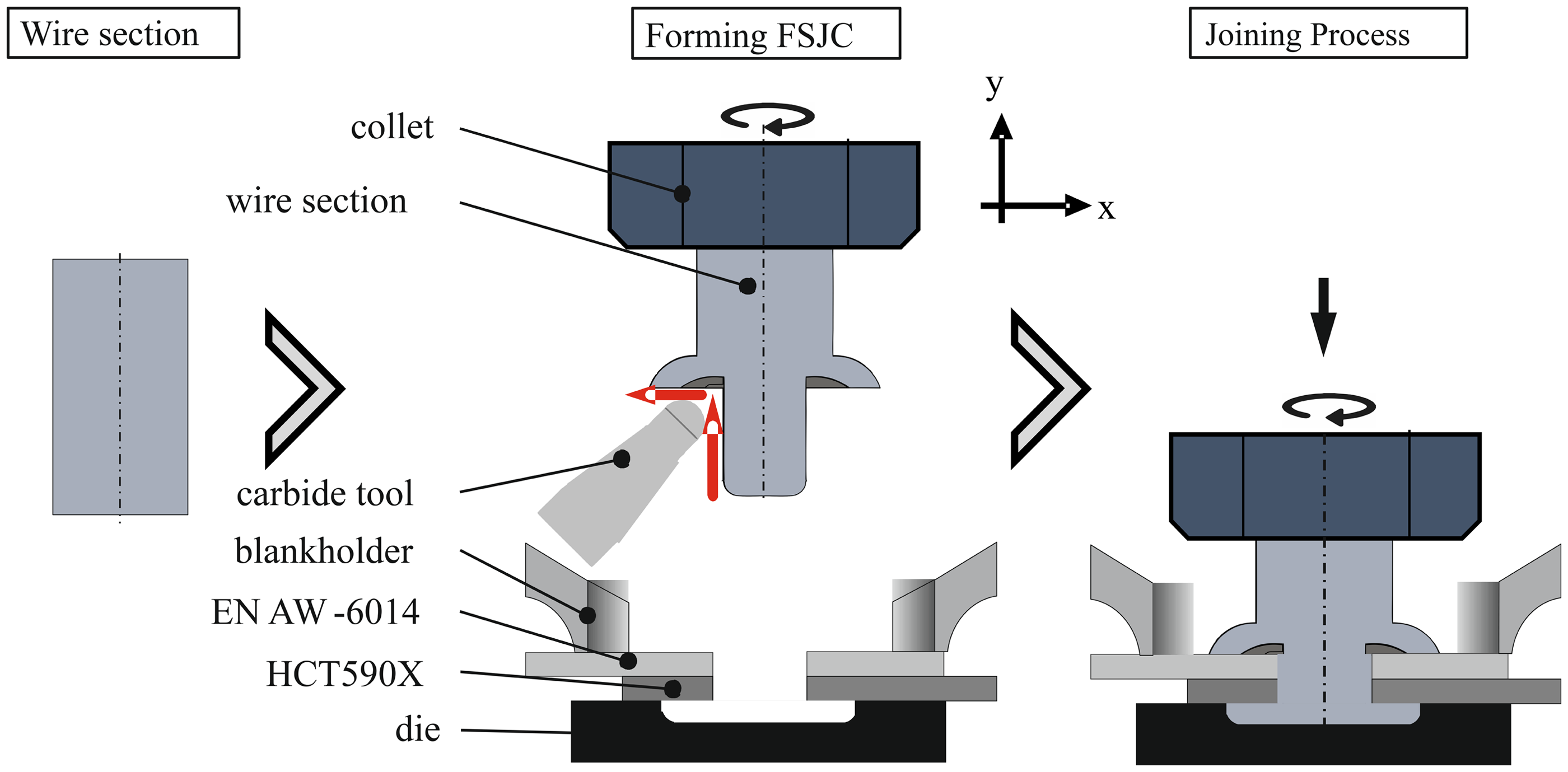
Process steps of the thermomechanical joining process with (a) user-individual manufacturing of the FSJC and (b) using the FSJC for joining two different sheets. FSJC: Friction Spun Joint Connector.
The second process step (shown in Figure 1(b)) describes the actual joining process of the previously produced FSJC (depending on the requirements of the joint). The FSJC, which is also clamped in the collet of the milling spindle for this step, is fed in the negative y-direction in the investigations described below and rotated through the sheets. Direct shear tensile specimens are manufactured from two overlapping metallic sheets with a pre-hole of d = 6 mm diameter. Due to the subsequent frictional contact with the die, the FJSC is heated, plasticised, and the strength is reduced. Along with the further infeed in negative y-direction, a closing head is formed which, together with the flange on the upper side, forms the positive locking of the joint. Finally, the joint is released from the collet and the excess part of the wire section is cut off.
In-situ computed tomography
When assessing the failure phenomena of joints, the typical approach involves conducting mechanical tests. Here, often only the force–displacement curves or the failure phenomena visible from outside are analysed. 12 In order to assess the local strain field at the outer surface of a joint during mechanical tests, digital image correlation techniques can be applied.13,14 However, the crucial deformation phenomena occur inside the joint during forming. To investigate those phenomena, macroscopic cross-sections are analysed, revealing the failure phenomena visible in a single cross-section at a certain displacement level (DL). 15
On the contrary, classical ex-situ computed tomography (CT) enables a comprehensive three-dimensional analysis of a joint. However, the effectiveness of this method is restricted due to the elastic springback 16 and closure of cracks 17 when unloading the specimen and preparing for CT. Furthermore, the progression of deformations or cracks cannot be analysed. The ex-situ CT can be upgraded to in-situ CT by combining the testing machine (TM) with a CT-system. Here, CT scans a performed at finely graded DLs while the specimen is loaded. This method was already applied to clinch points. For instance, the production of a clinched point is investigated in in-situ CT with regard to the validation of numerical models. 18 Additionally, it is shown in 19 that increasing deformations can be observed and numerical models can be validated in detail. Moreover, there are some application cases for other joints. Exemplarily, the damage evolution in thermoplastic fibre-reinforced plastics due to the loading of ultrasonic welded joints 20 as well as due to insert loading 21 is evaluated using in-situ CT.
The scientific goal of this paper is to investigate the internal deformations and the failure phenomena of FSJC during mechanical testing using in-situ CT. Therefore, joints that are thermomechanically produced are tested under tensile-shear load and the failure phenomena are investigated in in-situ CT. The specimens under investigation consist of different FJSC and sheet material combinations. Moreover, the influence of the in-situ CT testing procedure and of the in-situ CT test setup is evaluated. For this purpose, specimens are tested continuously both on a regular TM, and on the in-situ CT testing setup. Specimens consisting of aluminium FSJC-sheets combinations, of steel FSJC and aluminium sheets combinations, and steel FSJC-sheets combinations are investigated. The advantage of using in-situ CT in the mechanical testing of FSJC is that the internal material behaviour can be investigated and displayed as in a real failure case. In addition, information on the future design of the load-bearing cross-sections is to be obtained by characterising the internal surfaces and their changes over the mechanical load.
Methods
Joining and specimen preparation
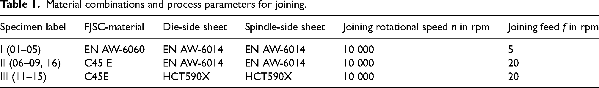
Different combinations of FJSC and sheet material are tested in order to highlight the versatility of the thermomechanical joining process. Both the age-hardenable aluminium alloy EN AW-6060 and the heat-treatable steel C45E with the diameter of d = 8 mm are used as the starting materials for the auxiliary joining elements. These elements are produced by forming at a rotational speed of n = 12,000 rpm for the aluminium alloy and n = 10,000 rpm for steel. The feed rate is f = 220 mm/min for the aluminium and f = 200 mm/min for steel. Due to similar sheet thicknesses of all combinations, all FJSCs have the same shaft length of l ≈ 7.3 mm. The diameter of the shaft of all auxiliary joining elements is d = 5.5 mm. A pre-hole with a diameter of d = 6 mm is drilled into all sheets (aluminium sheet EN AW-6014 has a thickness of t = 1.5 mm and steel sheet HCT590X t = 0.8 mm). All sheets have a length of l = 105 mm, a width of b = 37 mm and an overlap of Δl = 16 mm. To investigate the deformation and failure behaviour (FSJC or sheet side), three different combinations of sheet and auxiliary joining element material are investigated (Table 1). Due to the different properties (such as strength), different feed rates are used for the joining process itself depending on the FJSC-material.
Material combinations and process parameters for joining.
Test scenarios
To investigate the influence of the in-situ testing procedure, aside discontinuous in-situ CT tests, continuous tensile-shear tests are conducted. Moreover, these tests are conducted according to ISO 12996 using a regular TM (Figure 2(a)) and the in-situ CT testing device (in-situ-conti) (Figure 2(b)). Here, only the force–displacement behaviour is evaluated and compared with the in-situ CT data. All tests are conducted with the same testing speed. However, on the contrary to the preload of 5 N used in the TM, a preload of 50 N is applied using the in-situ CT test setup due to higher settling effects.
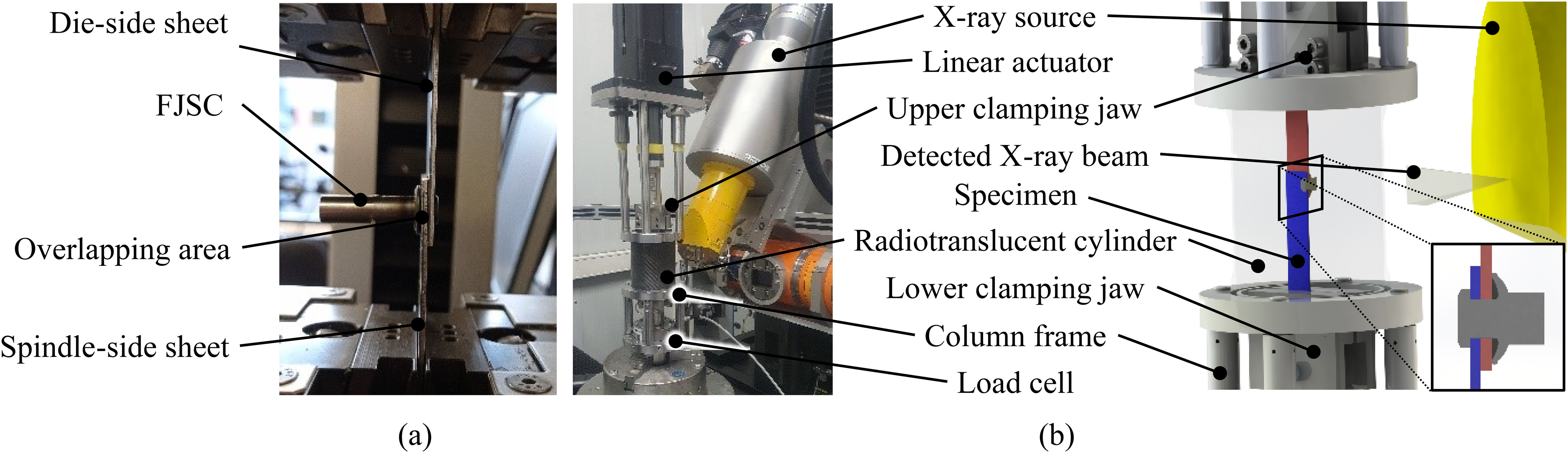
Exemplary investigated specimen mounted in the testing machine (a); the in-situ CT test setup with a built-in specimen (b).
The in-situ test setup consists of the V|TOME|X L450 a (300 kV microfocus, flat detector) and a testing setup designed for in-situ CT testing. The electromechanical linear actuator RSA-HT 64 b (max. force 58 kN) mounted on the column frame exerts a force on the clamped single-lap shear specimen. The actuator is driven by the servo motor AKM2G-51H c combined with the single-stage planetary gearing PLQE-120 d . The whole setup is rotated to enable X-ray projections from all angles during the CT scan. The in-situ CT parameters are given in detail in Table 2. After scanning, the projection images are processed for reconstruction of the digital volumes in phoenix datos|x 2 e . Finally, the volumes are digitally evaluated in VG Studio Max f .
In-situ CT parameters including the displacement levels (DL) chosen for in-situ CT scans.
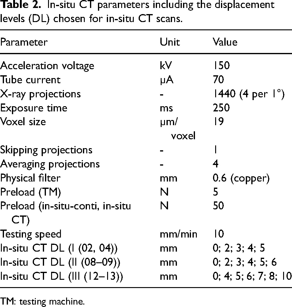
TM: testing machine.
Results and discussion
In this chapter, the force–displacement curves of the three different test scenarios are used along with the in-situ CT images to analyse the failure behaviour of three different joints. For this purpose, a pure aluminium, a pure steel joint (FSJC and sheet material comparable) and a mixed joint consisting of a steel auxiliary joining element with two aluminium sheets are considered and tested.
Aluminium FSJC and sheets
Initially, the pure aluminium specimens with the FSJC made of the wrought alloy EN AW-6060 as well as two sheets with a thickness of t = 1.5 mm of the alloy EN AW-6014 are considered. The force–displacement curves of the two continuous shear tensile tests (TM + in-situ-conti) along with the two discontinuous tests (in-situ CT) show good and high agreement with regard to the curve, the maximum forces and the displacement (Figure 3). This implies that the test setup used for the in-situ CT does not significantly influence the test conditions. Thus, the real failure behaviour of the joints can be depicted with the images generated and discussed in the following. Despite the very good agreement of the characteristic values, slightly different courses of the force–displacement curves occur in the initial phase of the test. This can be attributed to a small variation of the lateral distances between the sheets and the auxiliary joining element. These gaps combined with a lower preload in the regular tests lead to a different settling behaviour in the initial phase of the test, which, however, does not significantly influence the further course of the test.
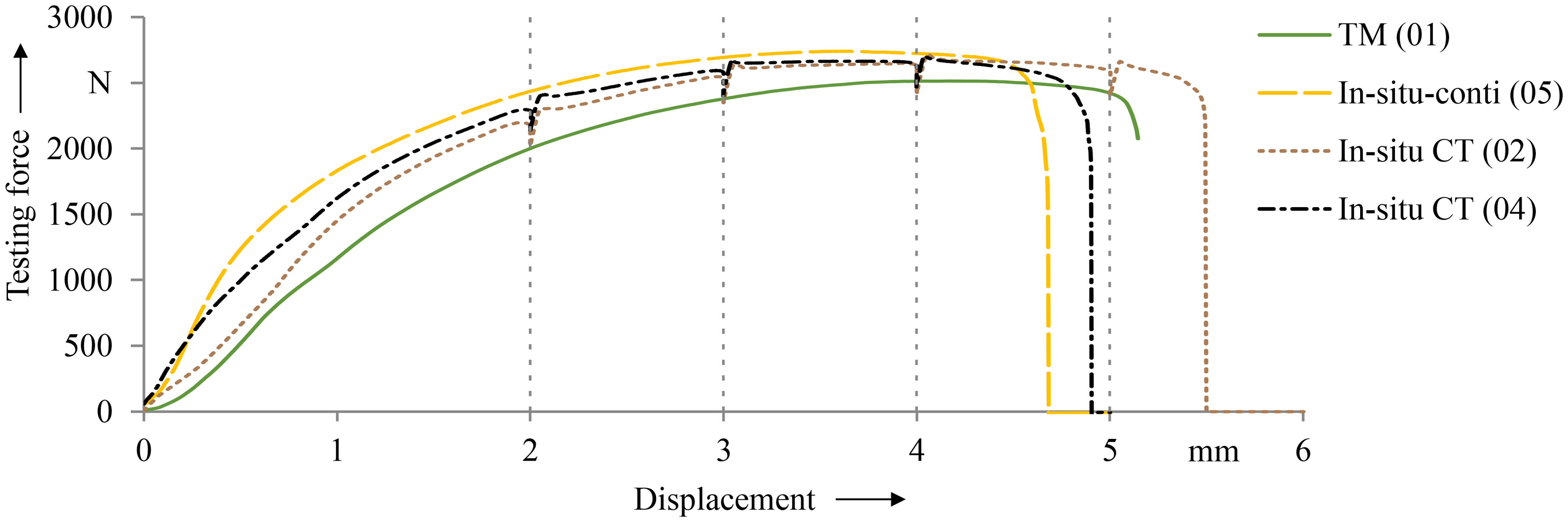
Force–displacement curves of TM, in-situ-conti and in-situ CT tests of aluminium specimens I with the marked DL. DL: displacement level; TM: testing machine.
In the first image of the in-situ CT scan, it can be identified that due to the pre-hole, there is only a very small and, in parts, no lateral contact of the FJSC with the sheets (Figure 4, 0 mm). By applying the shear tensile load and the associated tilting of the FSJC (2 mm, 3 mm), the contact area increases strongly (compression). However, this only applies to the two sheet parts that are diagonally opposite each other. As the FJSC and the sheets consist of the same material, there is a very low edge contrast at the highly compressed areas impeding a differentiation of the components. However, considering the ultimate shear failure of the FJSC and the displacement of the sheets, a very strong local shearing of the FJSC itself can be concluded.
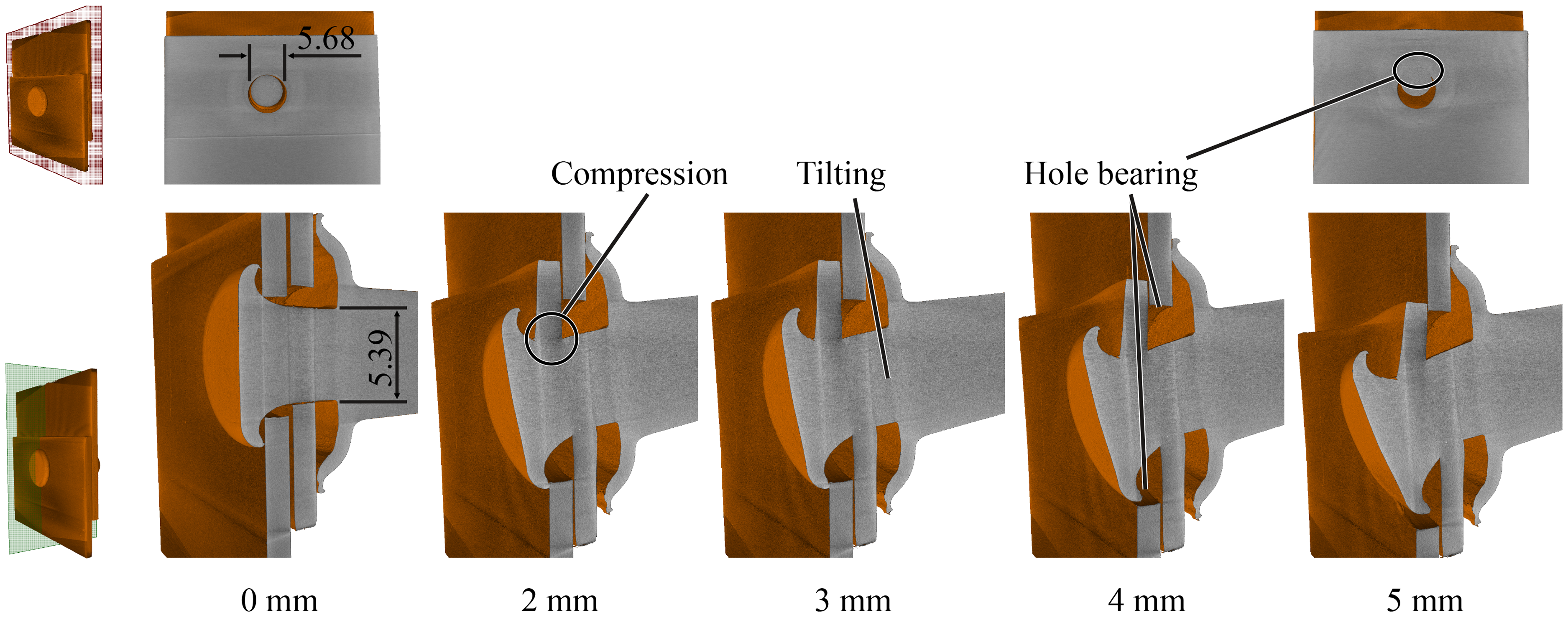
In-situ CT tomograms of specimen I (02) at the investigated DL. DL: displacement level.
Steel FSJC and aluminium sheets
The second material combination considered is the mixed connection of the FJSC made from the steel HCT590X and two aluminium sheets (EN AW-6014). Due to the shearing failure of the FJSC of the pure aluminium connection, the connection with the steel FSJC shows a higher strength Fmax > 3.5 kN in direct comparison (with otherwise comparable geometric parameters) (Figure 5). For the regular testing, there is a displacement step at low loads at the beginning of the test. Considering the lower preload of 5 N in the regular test and the gaps between sheets and FJSC caused by production (Figure 6, 0 mm), this can be caused by settling effects.
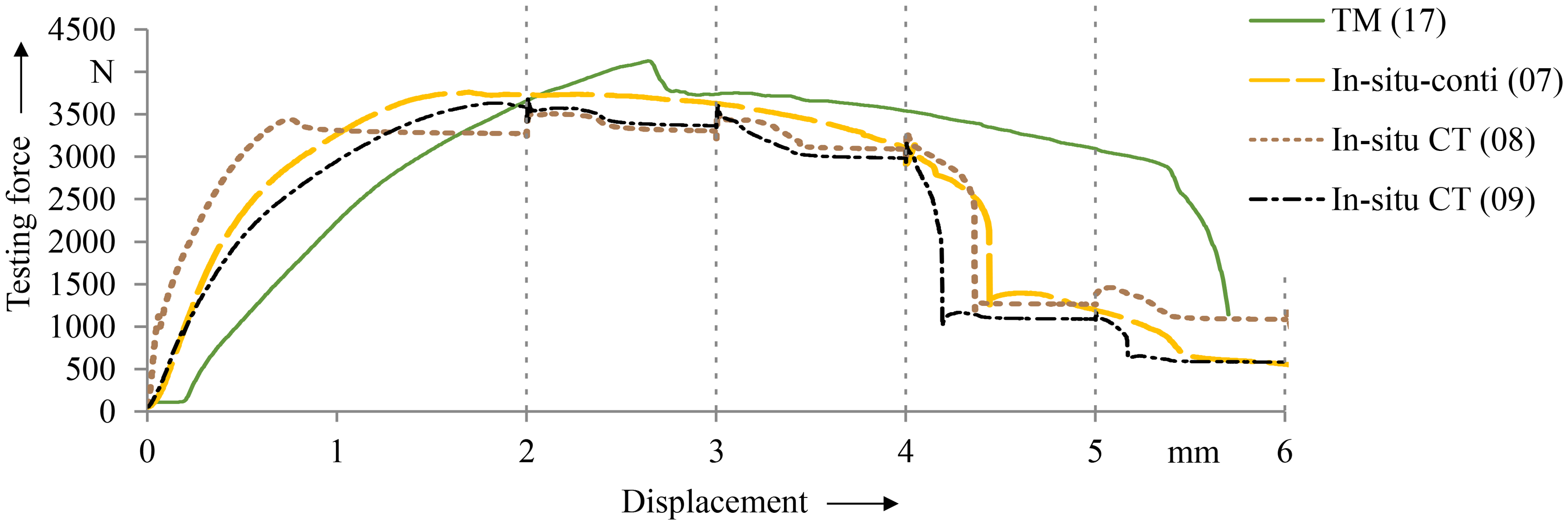
Force–displacement curves of TM, in-situ-conti and in-situ CT tests of specimens II with the marked DL. DL: displacement level; TM: testing machine.
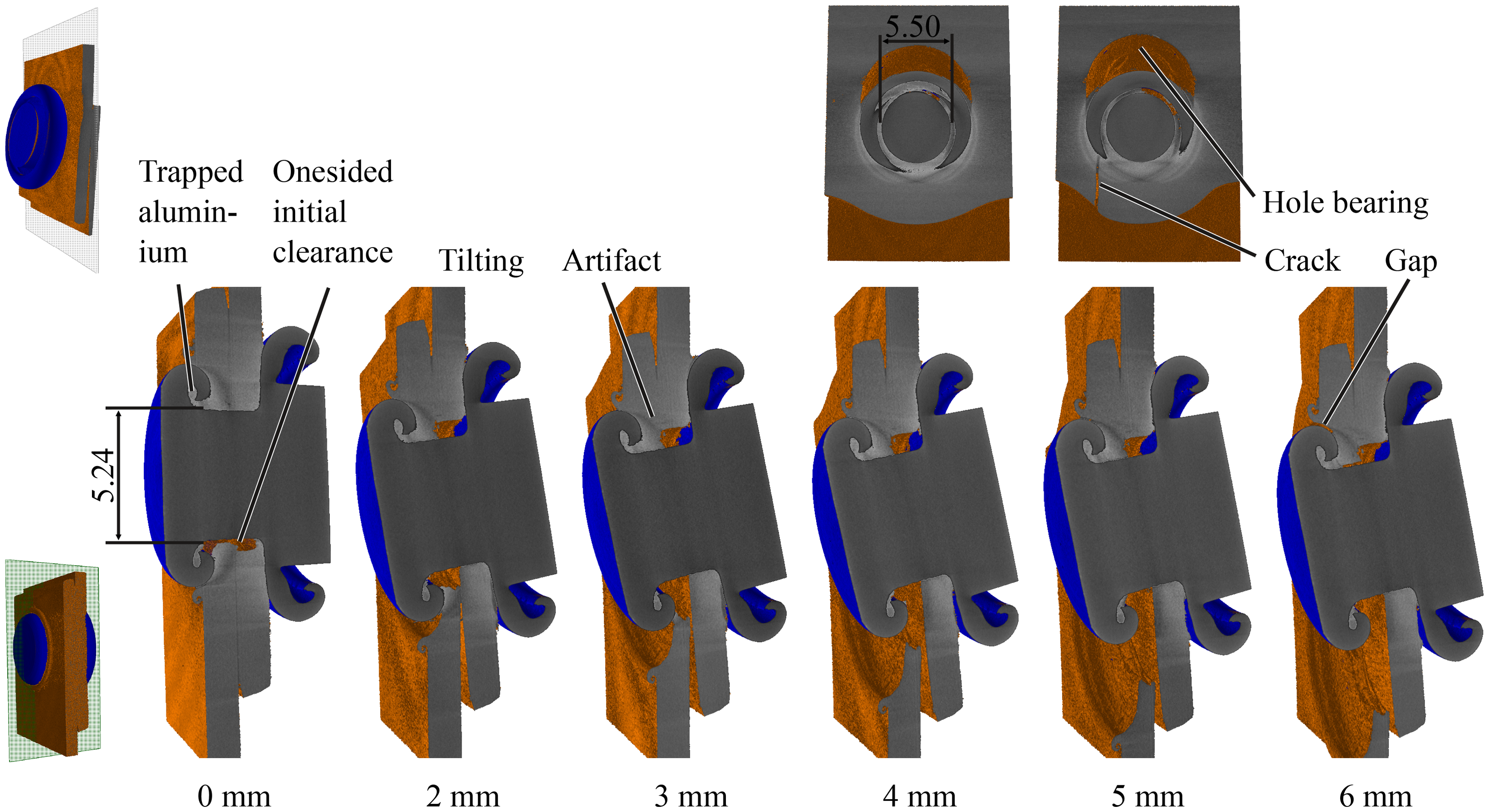
In-situ CT tomograms of specimen II (08) at the investigated DL. DL: displacement level.
For the pure aluminium joint, the closing head is formed behind the die-side sheet due to the comparable strengths of the sheets and the FJSC. Due to the different material in the steel FJSC aluminium sheets combination, a different closing head of the steel FJSC is formed. The closing head partly forms into the die-side sheet and traps some aluminium material behind the closing head (0 mm). The penetration leads to a reduction of the sheet thickness and thus to a weakening of the sheet, which can be seen in the CT images of the different DLs (2 mm, 3 mm). In direct comparison to the failure behaviour of the pure aluminium joint, a significantly lower tilting of the steel FJSC occurs (2 mm). Due to the higher strength of the steel FJSC compared to the sheet metal, the aluminium undergoes severe deformation resulting in hole bearing. This leads to shear-out failure, deduced from the drop in force between 4 mm and 5 mm (Figure 5) and the crack parallel to loading direction (5 mm). The opened crack allows the remaining sheet material to bend out revealing a gap towards the FJSC (6 mm).
Steel FSJC and sheets
The specimens with the pure connection of the steel auxiliary joint element and the two steel sheets show the highest strength, as expected. For this connection, too, the different test methods show an acceptable agreement with regard to the force–displacement curves (Figure 7).
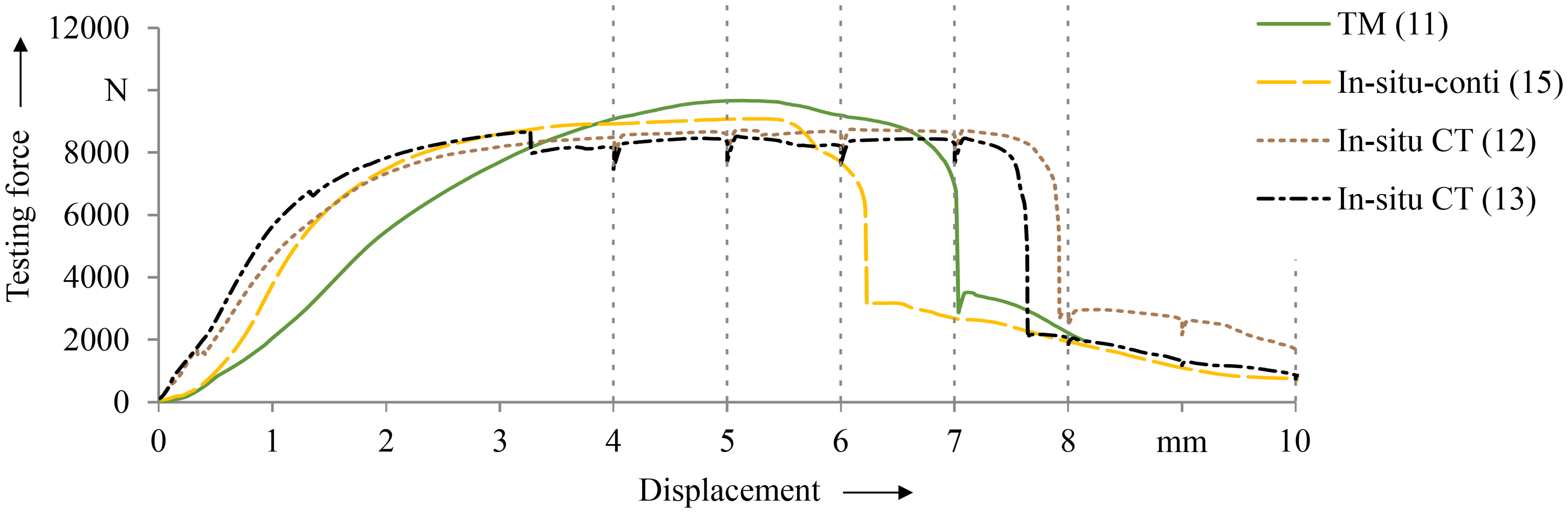
Force–displacement curves of TM, in-situ-conti and in-situ CT tests of specimens III with the marked DL. DL: displacement level; TM: testing machine.
Analogous to the other material combinations, a good form fit between closing head and flange, and the sheets is also shown for the unloaded state (Figure 8, 0 mm). Compared to the specimens with the steel FSJC and aluminium sheets, significantly higher maximum forces Fmax > 8 kN and a higher displacement is found for the pure steel joint. Due to a comparable strength of the FJSC as well as the sheets, a significantly stronger tilting of the FSJC occurs here (5 mm). In an early loading phase (4 mm, 5 mm), a crack also appears in the closing head and part of it is cut out. However, since this only occurs partially and the closing head otherwise still covers a large part of the die-side sheet metal, this does not lead to joint failure. Due to the tilting of the FJSC, there is high compression between the FSJC and the sheet metal, so that the two components cannot be differentiated any more. With increasing hole bearing of the die-sided sheet, a crack appears in the sheet (7 mm, 8 mm), causing the force drop in Figure 7 and the joint failure.
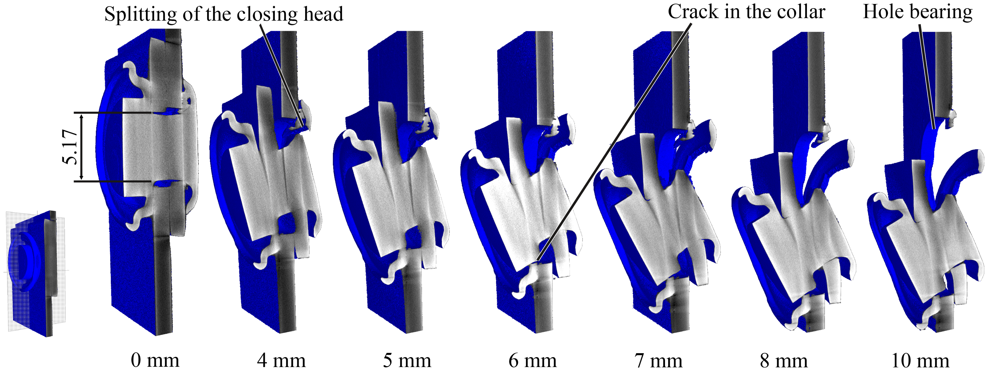
In-situ CT tomograms of specimen III (13) at the investigated DL. DL: displacement level.
Comparison of failure behaviour
The comparison of the three different material combinations of sheets and FSJC show varying behaviour with regard to joint settling and stiffness and moreover to strength and failure type. For the initial stiffness, the combination of an aluminium sheet and a steel FSJC (specimen type II) shows the best results of the investigated joint combinations. The reason for the higher initial stiffness is likely the closing head that partly formed into the sheet, creating an additional form fit. When using a FSJC of the same material as the sheets (here specimen type I), there is a tendency for a shearing failure of the FSJC shaft and the joint fails with a sudden force drop. If the FSJC has a higher strength than the sheet material, the joint fails gradually, absorbing more energy and resulting in a hole bearing failure. The tilting of the FSJC is apparently related to the strength ratio of the sheet and FSJC material. The investigated specimens showed a higher tilting at comparable strength of the sheets and FSJC.
To achieve a high-performance joint, the joints should be gap-free in the hole bearing, which leads to a high initial stiffness and the FSJC should have a higher shear strength than the sheet material for an overall high-strength joint. Furthermore, the FSJC flange shape should be formed concave towards the sheet so the form fit is maintained to the edge of the flange (compare to Figure 1) and leads to a higher resistance against tilting and shear-out of the joint. Also, the forming of the closing head should be executed in such a way that no thinning or damaging of the sheet occurs.
Conclusion
In this paper, joints that are thermomechanically produced are tested under tensile-shear load. Particularly, specimens consisting of pure aluminium FSJC-sheets combinations, of steel FSJC and aluminium sheets combinations, and pure steel FSJC-sheets combinations are investigated. To analyse the failure phenomena, the testing process is performed in in-situ CT. Furthermore, specimens are tested continuously both on a regular TM, and on the in-situ CT testing setup. Thus, an influence of the in-situ CT testing procedure and of the in-situ CT test setup can be analysed.
Regarding the force–displacement behaviour no significant impact of the in-situ testing procedure or the setup can be found. However, the gaps between FSJC and sheets caused by production as well as the lower preload applied in the regular tests lead to a different force–displacement behaviour at the beginning of the testing. Using the in-situ CT investigation, the deformations in joints and the failure mechanisms are analysed. Thus, regarding the pure aluminium joint, the sheets create a high local shearing force on the joint causing the ultimate joint failure. The specimen consisting of steel FSJC and aluminium sheets shows hole bearing resulting in shear-out failure of the sheet. Caused by production the FSJC partly forms into the die-side sheet. Due to this weakening of the sheet, it can be concluded that the formation of the closing head has to be improved in future investigations in order to prevent weakening of the sheet and thus further improve the strength and the displacement at ultimate failure of the mixed joint. The pure steel joint reveals a gradual failure of the closing head and the flange combined with hole bearing. However, the ultimate failure is caused by shear-out of the joint.
This investigation shows that in-situ CT is well suited to analyse the failure behaviour even from mixed materials including highly X-ray absorbing materials such as steel. Likewise, the limitations of this method are shown when components of the same material are highly pressed together as the components cannot be differentiated any more. In future investigations, it will be necessary to investigate whether these contact pressures can cause cold welding of the different components.
Footnotes
Acknowledgements
This research was funded by the German Research Foundation (DFG) within the project Transregional Collaborative Research Centre 285/2 (TRR 285/2) (project number 418701707), sub-project C04 (project number 426959879) and sub-project C03 (project number 426958705).
Declaration of conflicting interests
The author(s) declared no potential conflicts of interest with respect to the research, authorship, and/or publication of this article.
Funding
The author(s) disclosed receipt of the following financial support for the research, authorship, and/or publication of this article: This work was supported by the Deutsche Forschungsgemeinschaft.