
Abstract
In a previous study (part I), the deposition of functional single-track and multi-layer Ni-rich NiTi using the electron beam freeform fabrication (EBF3) technique was demonstrated. The processed microstructure consists of columnar millimetre range grains that grow parallel to the build direction. Based on the same parameters of part I, this work successfully deposited a stable multi-track and multi-layer NiTi block. Different heat treatments were applied to modify the superelastic properties of the deposited material. Initially, the solution treatment reduces the chemical inhomogeneity and the thermal stresses that originated during the deposition and cooling. Subsequently, due to ageing, Ni4Ti3 particles precipitate at 350 °C and 450 °C for 1, 6 and 12 h, modified the superelastic behaviour of the deposited NiTi. The differential scanning calorimetry results did not reveal any difference in the martensitic starting temperature between as-built and solution-treated samples. However, a remarkable influence of the ageing temperature was detected: while ageing at 350 °C impacted R-phase starting temperatures, 450 °C altered the martensitic starting one. The superelastic behaviour was evaluated by cycling compression. As-built and solution heat-treated samples presented poor mechanical performance, with about 40% of strain recovered after 10 cycles. The ageing at 350 °C for 1 h led to a maximum measured strain recovery of 72.5% after 10 uniaxial compression cycles up to 860 MPa. This condition also resulted in 3.3% permanent deformation out of 11.3% of the total. This study addressed for the first time the fabrication by the EBF3 technique of a stable multi-track and multi-layer NiTi block besides the importance of heat treating it, demonstrating that this post-treatment improves the superelastic performance of EBF3 fabricated parts.
Keywords
Introduction
Recently, the fabrication of NiTi parts by additive manufacturing has gained importance. Powder-based techniques such as powder-based directed energy deposition (DED) 1 and laser-powder bed fusion (PBF-L)2,3 were broadly explored to produce this material. Both techniques can produce NiTi parts with excellent strain recovery and functional properties, fulfilling engineering application requirements.4–7 However, higher deposition rates, improved energy efficiency and lower feedstock losses are required to produce defect-less, high-density parts.8,9 In this sense, NiTi can be fast-produced using wire-based DED additive techniques. These techniques are wire-arc additive manufacturing 10,11 and electron beam freeform fabrication (EBF3).12–18
The first work on EBF3 of NiTi was published by Dutkiewicz et al. 12 The authors compared the physical properties, microstructural features and superelastic behaviour of Ni50.97Ti (at. %) NiTi alloy fabricated by both EBF3 and laser-engineered net shape (LENS). The authors showed better superelastic compression behaviour of the LENS samples compared to EBF3 in the as-built condition. In contrast, the EBF3 samples presented higher superelastic recovery after ageing at 500 °C for 2 h. Li et al. 13 produced wall-structured parts with Ni50.7Ti depositing it over a commercially pure Ti plate, an alternative to reduce the use of expensive NiTi substrates. A stable region composed of austenite was formed above the transition Ti-NiTi layer. The superelastic and damping capacity evaluation revealed that 80% of the strain was recovered after 10 cycles in the tensile mode for samples taken along the build directions. Pu et al. 14 printed a single-pass multi-layer component of Ni50.8Ti. The deposition's bottom, middle and top parts revealed that the transformation temperatures (TTs) depend on location in the as-built condition. The superelastic behaviour also presented variations depending on the sample location. When mechanically cycled in tensile mode – 10 cycles with 6% of constant deformation on each, the samples presented the irrecoverable strain from 1.7 (bottom), 2.8 (middle) and 2.3% (top). This behaviour has changed after solution (750 °C, 1 h) and ageing (250 °C for 48 h) treatments were carried out; the irrecoverable strain span was reduced to 1.5 (bottom), 1.6 (middle) and 1.2% (top). In other words, by heat treating the sample, one can reduce the height dependency of the properties besides improving the mechanical performance of the part.
Most of the studies about AM of NiTi focused on single- or double-walled structures. Consequently, there are no investigations in multi-track and higher depositions (of blocks) in the literature. When the upscaling to multi-track is applied, the heat flux through the deposition changes significantly due to the deposition strategy. Therefore, the resulting solidified microstructure influences the grain orientation, precipitation distribution/size, texture, thermal/internal stresses and defect distribution.19,20 These microstructural characteristics have implications on the strain recovery, as well as on the phase TTs.13,18,21 Apart from the work of Dutkiewicz et al. 12 and Pu et al., 14 there is not enough information in the literature about the impact of the post-heat treatment on the compressive superelastic behaviour of EBF3-fabricated parts.
Based on the abovementioned needs, the present work aims to correlate the solution and ageing heat treatments with the phases and mechanical response of NiTi samples fabricated by EBF3. This work follows up our previous part I publication, 22 which focused on manufacturing single tracks with 1, 5, and 10 layers of Ni-rich NiTi alloy to produce a stable, functional single-walled EBF3 structure. The earned experience allowed fabricating blocks of five tracks and 20 layers, that is, 100 weld tracks. This deposition was suitable for producing functional samples, later subjected to solution post-treatment at 950 °C and subsequently aged at 350 °C and 450 °C to precipitate Ni4Ti3 particles (as already explored by the PBF-L of Ni-rich NiTi 23 ). The effects of these heat treatments are correlated to the microstructural features, thermophysical behaviour and the improvement of the superelastic strain recovery in compressive cycles.
Materials and methods
Electron beam freeform fabrication
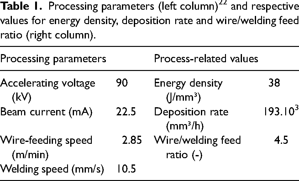
The nominal chemical composition of the as-drawn Φ1.2 mm wire was Ni51.2Ti48.8. The wire was deposited over a 10 mm thick equiatomic Ni50Ti50 substrate. EBF3 was conducted in a Pro-Beam EBG45-150-K14 electron-beam welding machine (Pro-Beam, Germany). The process parameters of the previous work 22 were employed. Also, the correspondent energy density, deposition rate and wire/welding feed ratio values 24 are listed in Table 1. The electron beam was deflected circularly to obtain figures of concentric circles with a maximum diameter of 4 mm. The value of the lens current guaranteed the focal position on the substrate's surface or the previously deposited layer.
Processing parameters (left column) 22 and respective values for energy density, deposition rate and wire/welding feed ratio (right column).
The built block consisted of 20 layers. Each layer comprised five tracks 130 mm in length deposited side by side unidirectionally with 65% of overlap. The welding sequence and overlap distance were selected according to the literature.25–28 The alternate-line path ensured a stable build-up process with geometric accuracy of the fabricated parts (see Figure 1). The obtained width of the block is approximately 22 mm, and the height is around 23 mm.
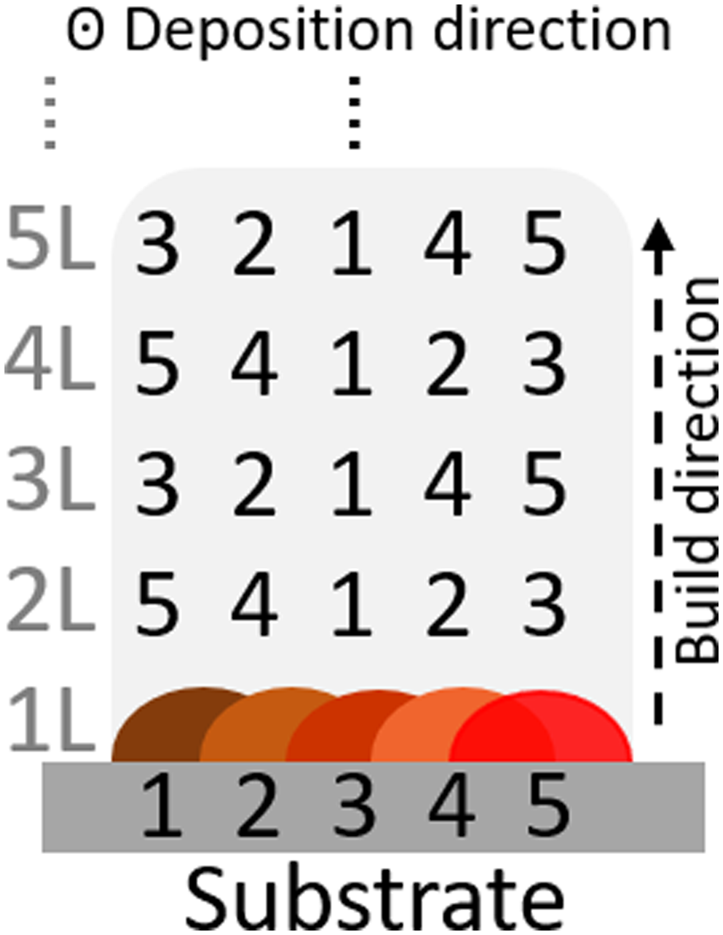
Deposition strategy adopted for the fabrication of the block. 1L, 2L, etc., represent the layer number, while 1, 2, etc., represent the bead deposition sequence.
Sample machining and cutting
Electro-discharge machining was used to extract samples from the built block. Considering the building direction, Figure 2 shows the machining positions: (a) cylinders with 8 mm in diameter and 12 mm in length and (b) 2 mm thick cross-section samples. These were cut at the half-height of the built block to have a sample composed solely of feedstock. Additionally, cross-section samples were extracted for microstructural analysis and phase identification. The cylinders enabled the evaluation of the superelastic behaviour of the deposited material by compression tests. A precision cut-off machine was used to remove differential scanning calorimetry (DSC) and X-ray diffraction (XRD) samples from the cross-sections to avoid any thermo-mechanical influence of specimens during preparation.
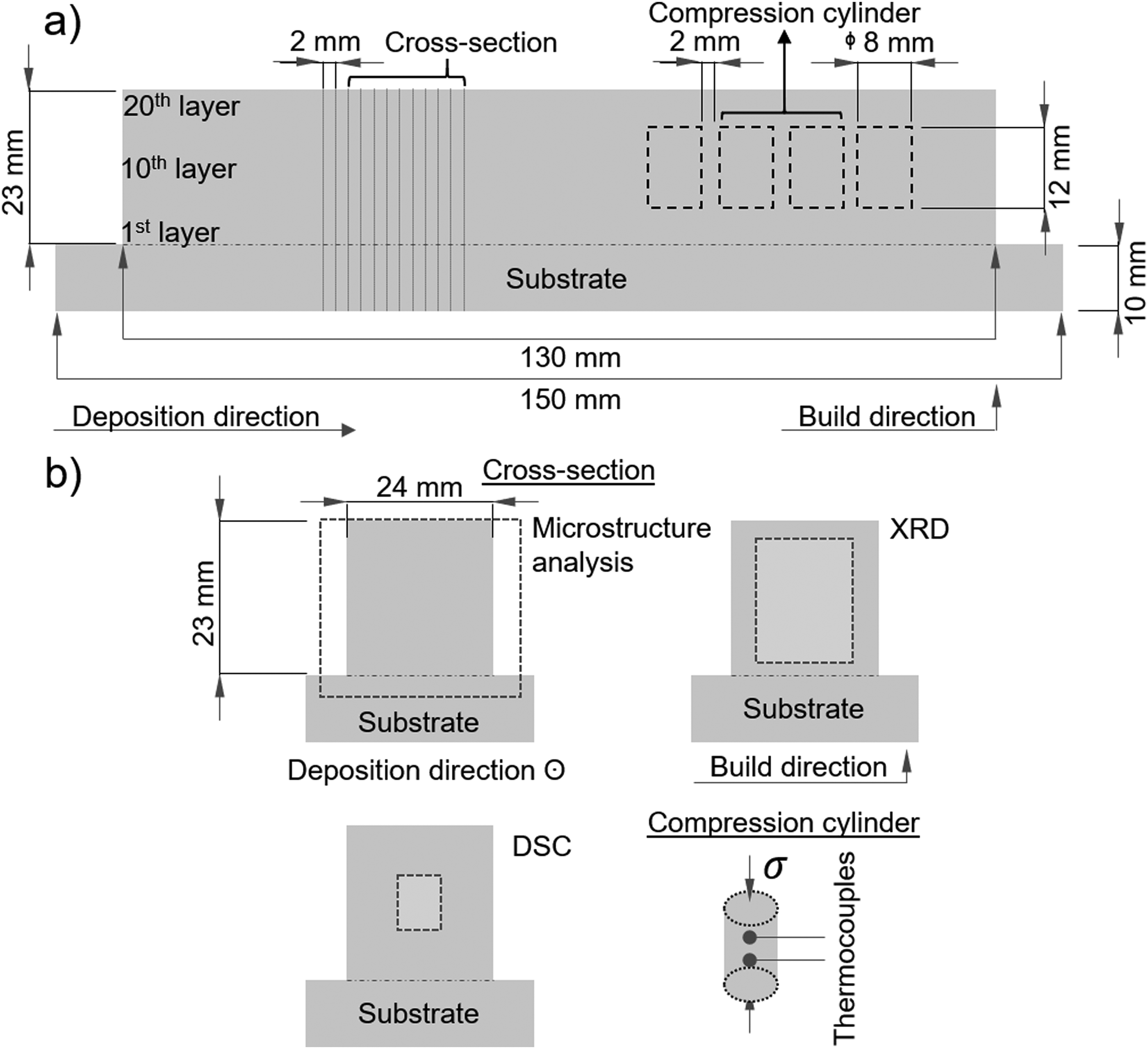
Representation of the (a) built block with the indication of dimensions, layer number and dimensions of the cross-section and compression cylinder as well as their locations on the built part. In (b), the cross-section shows where the microstructure, X-ray, and DSC analysis were made; a separated region shows the compression cylinder, the direction of applied stress (σ), and the position of the thermocouples welded on the surface of the sample.
Heat treatments
The solution and ageing treatments were carried out in an argon atmosphere to prevent the oxidation of the samples. The same heating rate of 20 °C/min was applied in both treatments. As-built (AB) samples were solution treated at 950 °C for 6 h, followed by water quenching to obtain a supersaturated homogeneous solid solution. Some solution-treated samples (SOL) were then aged at 350 °C and 450 °C for 1 h (designated 350-1 h and 450-1 h, respectively), 6 h (350-6 h and 450-6 h) and 12 h (350-12 h and 450-12 h) followed by water quenching.
Microstructural analysis and physical characterization
The microstructural investigation was carried out through light optical microscopy (LOM) and scanning electron microscopy (SEM). LOM samples were metallographically prepared using standard specimen preparation procedures, finalizing them within 30 min with a solution of OPS 5 microns (Struers, Germany). The microstructure was observed through an Axio Observer 7 microscope (ZEISS, Germany). A Mira3 microscope (Tescan, Czech) was used for the SEM analysis, operated at 15 kV, 8.5 mm of working distance and 10−4 mbar of vacuum. The phase transformations were determined by DSC in a PerkinElmer DSC-8500 (PerkinElmer, USA) using 10 °C/min heating and cooling rates. The DSC samples weighing 50–70 mg were thermally cycled from −60 to 100 °C. The cycle started by cooling the sample from room temperature to −60 °C, holding it for 1 min, heating it to 100 °C, holding it for 1 min, and finally cooling it to room temperature. XRD tests were performed on the polished cross-section of the samples aiming to determine the different phases at 25 °C using a Rigaku MiniFlex600 (Rigaku, Japan) diffractometer with filtered Cu-Kα radiation. Before the DSC and XRD measurements, the samples were etched in a solution composed of HNO3 (40 ml), HF (50 ml) and H2O (10 ml) to remove the stress-induced martensite (SIM). The XRD spectra were plotted with the as-received data. The DSC results were plotted after a baseline correction using the OriginPro® software version 20210 (OriginLab, USA).
Mechanical assessment of the superelasticity
The superelastic behaviour of Ni51.2Ti48.8 was investigated by uniaxial cyclic compression tests carried out on a Gleeble® 3800-GTC thermo-mechanical simulator (DSI, USA). These tests aimed to determine strain recovery stabilisation in the superelastic regime. Cylindrical samples (8 mm diameter×12 mm height) were heated up to 15 °C above the austenitic finish temperature (Af) and compressed to 860 MPa for 10 cycles at a load/unload rate of ±602.5 N/s. The temperature was controlled by a K-type thermocouple welded at the mid-span of the surface of each sample. A titanium-zirconium-molybdenum anvil was selected due to its high strength and toughness.
Results and discussion
Deposition stability
Figure 3 depicts a bulky sample built with five tracks and 20 layers of NiTi, that is, 100 tracks. One can observe a homogeneous block with regularly deposited layers and a slight hump approaching the end of the deposition. 10 mm of offset was employed at the beginning and the end of the deposition length, that is, within these offset parts, the steady state of the melt pool was not attained. Thus, the deposition is stable after and before the initial (slope-in) and final (slope-out) offsets. The samples were taken from the region between the white dashed lines in Figure 3 to guarantee stable processing conditions.
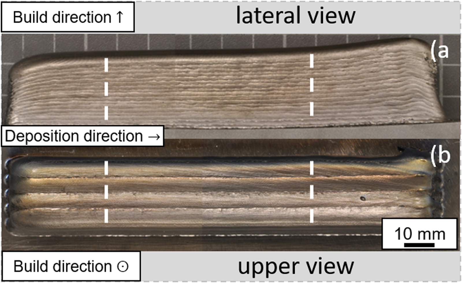
The macro image of EBF3-NiTi deposition of five tracks and 20 layers shows (a) lateral and (b) upper views of the built sample. The white dashed lines in (a) and (b) limit the stable region from where the samples were cut.
Microstructure evolution after solution treatment
Figure 4 depicts LOM and SEM images of AB and SOL samples. Figure 4(i) locates where each image was taken in the cross-section. In the block cross-section, Figure 4(a) and (b) shows millimetre size columnar austenitic (B2) grains oriented parallel to the build direction in both AB and SOL conditions. Figure 4(c) and (d) shows grains located between the 10th and 20th layers, more specifically close to the edge of the block. One can notice that the orientation of these grains slightly deviates from the build direction, being angularly oriented.
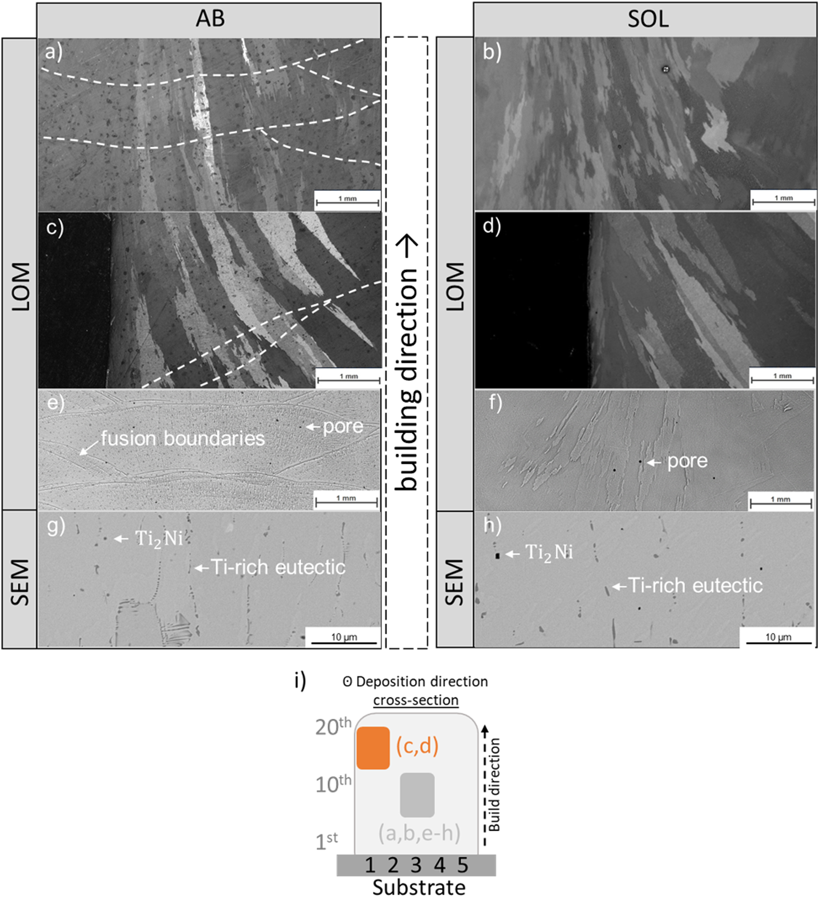
Cross-section images taken by (a–f) LOM and (g, h) SEM of AB (a, c, e, and g) and SOL (b, d, f, and h) samples; (i) is the location of where the images were obtained, while (a, b, and e–h) were taken around the 10th layer, (c) and (d) were images in the outer part between the 10th and 20th layers. The dark spots in (a) and (c) correspond to etchant artefacts.
The epitaxial growth of these grains takes place due to (i) the reduction of temperature gradients at the solidification front and (ii) the partial re-melt of once-deposited layers. EBF3 is considered a high-energy density process, and austenitic NiTi has a relativity low thermal conductivity coefficient of 10 W/m·K 29 (for instance, pure copper has 385 W/m·K 30 ). So, (i) takes place because of the as-deposited layer pre-heating effect, which is fostered by the combination of accumulated heat due to its low flow. Re-melting these pre-heated layers – (ii) – provides inhomogeneous nucleation sites at the melt pool boundary. Hence, the growth keeps progressing through the heat extraction direction, resulting in noticeable columnar grains oriented parallel/nearly parallel to the local heat flow direction.10,12,14,22,31 These grains continuously grow through the fusion boundaries shown in Figure 4(e), keeping their orientation even after the solution treatment (Figure 4(f)). Figure 4(g) depicts the AB microstructure composed of Ti2Ni particles embedded in cellular grains. Besides, a eutectic Ti-rich structure is formed due to the solidification conditions. 22
The grain orientation results from the deposition strategy depicted in Figure 1, which influences the heat flow direction. The grains in the first deposited track (bead #1 in Figure 1) grew columnarly. Following the deposition, the re-melting of these columnar and parallel to the build direction grains still produce large solidification gradients, resulting in further columnar growth. The solidification conditions differ for the outer beads that are the last to be deposited in each layer (cf. beads #3 and 5). The layer has an additional lateral ‘neighbour track’ to re-melt, resulting in a ‘rotated’ fusion zone due to the ‘rotated’ temperature gradient. Therefore, these outer bead grains grow angularly oriented following the rotated direction of heat extraction. 32
Figure 4(g) depicts the AB microstructure composed of Ti2Ni particles embedded in cellular grains, delimited by the Ti-rich eutectic phase. The eutectic phase is formed due to the solidification conditions 22 and the cellular grains due to the low local temperature gradients. The solution treatment modified the morphology of this Ti-rich eutectic from aligned drops to lamellas (see Figure 4(h)) due to surface free-energy reduction by coarsening. However, this treatment could not dissolve all the Ti2Ni particles. Therefore, one can conclude that higher temperatures than 950 °C must be employed to reach a B2 matrix free of Ti2Ni particles. 33
The results of the XRD of both AB and SOL are displayed in Figure 5. The results reveal an austenitic matrix (B2) for the sample in the SOL condition and B2 plus martensite (B19’) and Ti2Ni particles for the AB condition. The presence of B19’ in the AB condition was already explained by Oliveira et al. 34 for the heat-affected zone of laser-welded Ni50.8Ti plates. Their study found that martensite is present at room temperature because the residence time in the temperature range of 350–500 °C during the cooling stage induces Ni4Ti3 precipitates. These precipitates shift the martensitic starting temperature (Ms) to higher values due to the Ni depletion in the matrix; therefore, the Ms can reach room temperature. Moreover, Ms may also be shifted in the fusion zone because Ni is prone to volatilize due to the high-energy electron beam. The latter may be present in the whole deposition. Figure 5 shows a decrease in the (110) diffraction peak in the SOL compared to the AB material. The same effect is seen for the (200) peak. Nonetheless, the solution treatment is responsible for mainly increasing (200) relative peak intensity or, in other words, for creating orientation preferences. 35
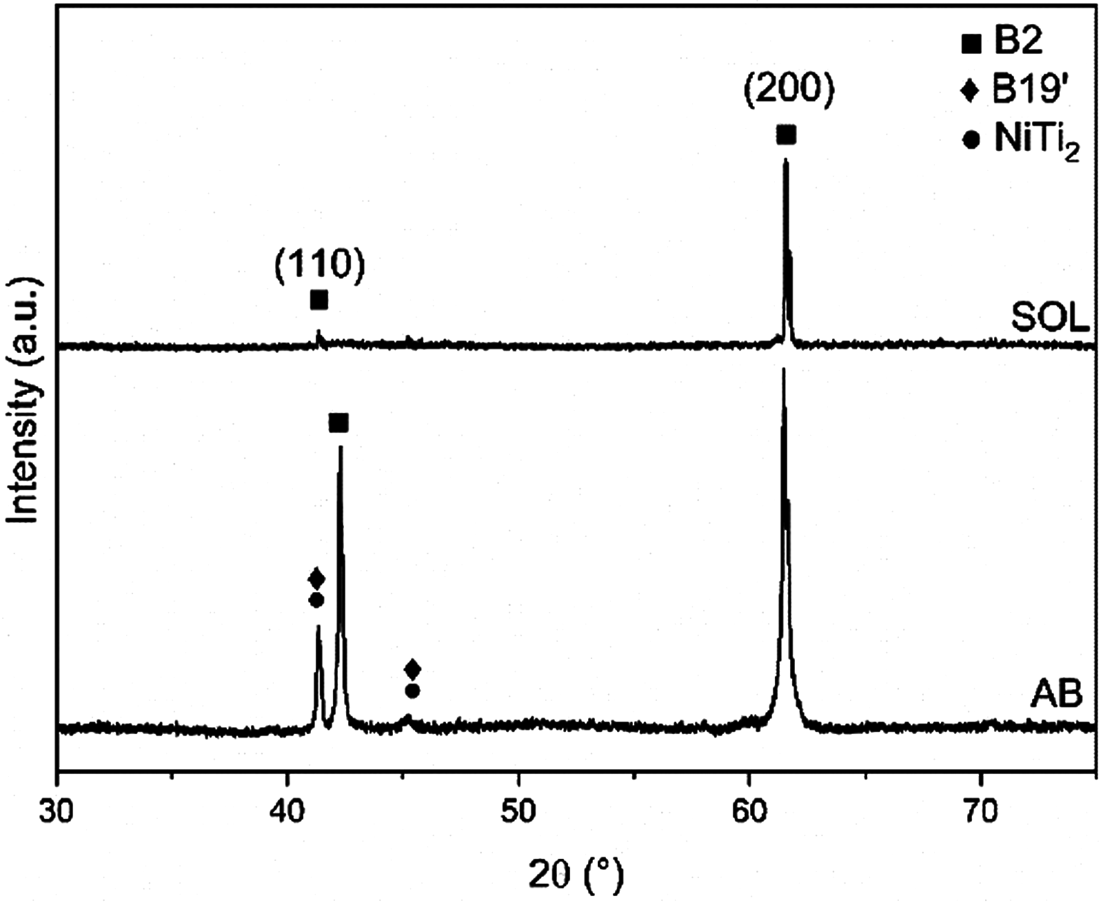
XRD spectra of AB (bottom) and SOL (top) samples.
Effect of ageing treatment on the transformation behaviour
The ageing treatments precipitate coherent metastable Ni4Ti3 particles that enhance the superelastic response. These Ni-rich particles provoke the depletion of Ni in the matrix that, as discussed before, affects the TTs. Therefore, the TTs can be tailored by controlling ageing time and temperature.36–39 Moreover, decreasing the Ni content can foster B19’ and R-phase – or the rhombohedral phase –transformation depending on the lattice distortions (or strain field) around this precipitate. This way, R-phase may suppress B19’ transformation depending on the size and distribution of the Ni4Ti3 precipitates. In other words, a competitive mechanism determines the functional stability and the phase transformation behaviour of the NiTi alloys. 40 The heat treatments applied here stress how the different ageing conditions affected the transformation behaviour of the EBF3-produced samples.
The DSC results are displayed in Figure 6: in (a), AB and SOL conditions are compared in both heating and cooling cycles, and (b) and (d), and (c) and (e) show the heating and cooling cycles for samples aged at 350 °C and 450 °C, respectively compared to the SOL condition. Based on Figure 6, the martensitic (Ms) and R-phase (Rs) starting transformation temperatures were determined during the cooling stage. In Figure 7, both temperatures are plotted along with the ageing time.
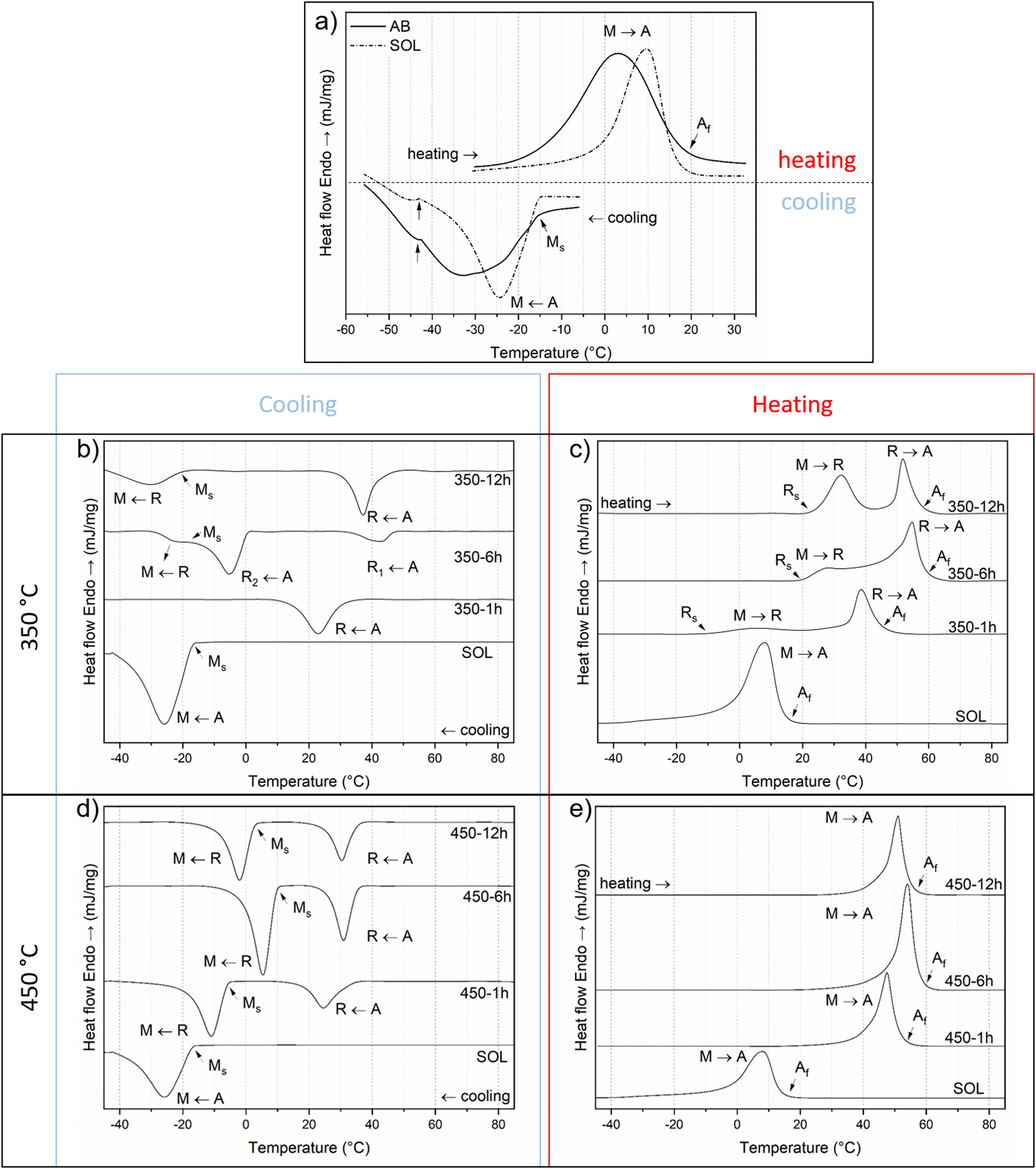
DSC profiles of (a) as-built and solution-treated, and solution-treated and aged at (b, c) 350 and (d, e) 450 °C for 1, 6, and 12 h. The blue square around (b) and (d) indicates the cooling cycle, whereas the red one encloses (c) and (e) the heating one – indexing according to.41, 42 M: martensite; A: austenite; R: homonymous; Ms: martensitic starting temperature; Rs: the homonymous starting temperature; Mf: martensitic final temperature.
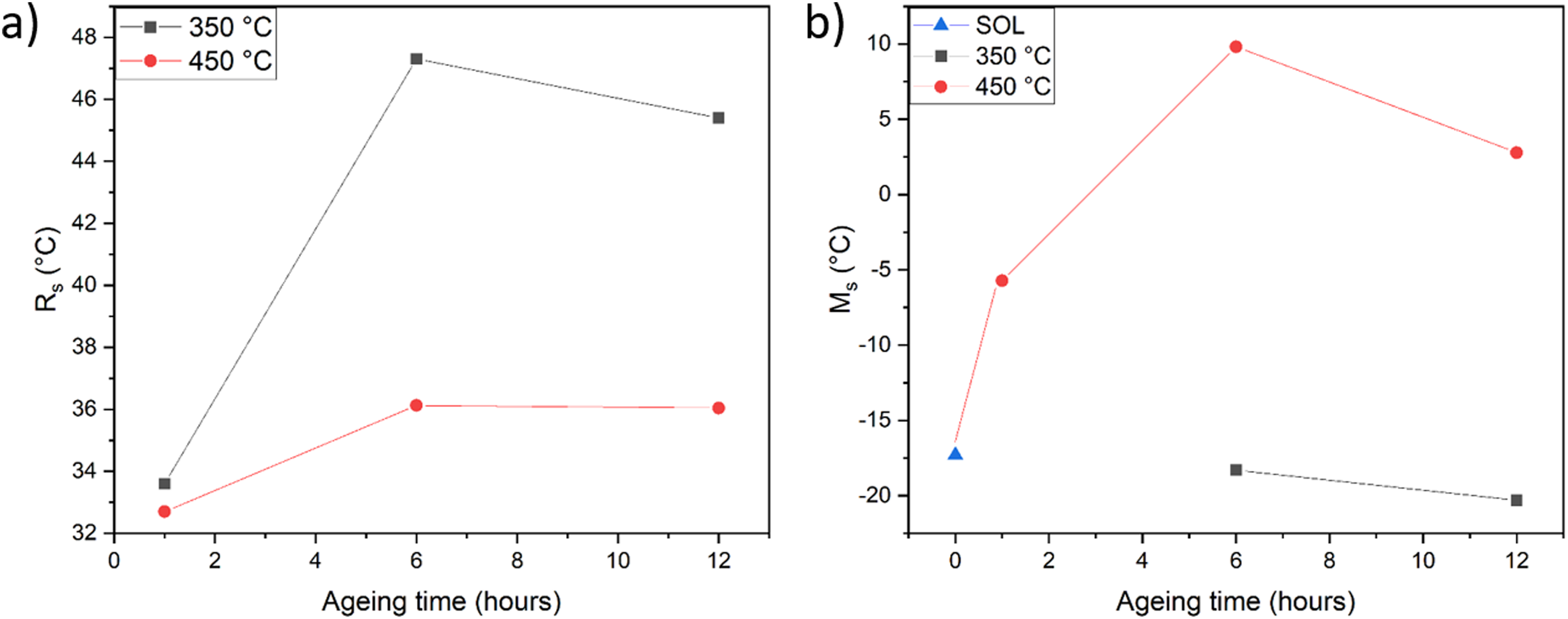
(a) Rs and (b) Ms temperature variations with the ageing time.
Figure 6(a) shows that the martensitic transformation is characterized by a narrower peak in the SOL condition compared to the AB-treated sample. A broad peak may represent local differences in the chemical composition through the matrix, which are mitigated by applying a solution treatment, thus resulting in a narrower peak. Energetically speaking, a more favourable phase transformation takes place:43–45 the transformation rate is higher in SOL than in AB, which takes place gradually due to the broader peak.
Ms has the same value before and after solution treatment because there is the same amount of Ni in the B2 matrix for both conditions. 46 According to the phase diagram of NiTi, 47 at 950 °C, the matrix is composed solely of a single phase, where Ni has complete solubility in the NiTi matrix. The solubility of Ni in the NiTi matrix decreases when the temperature decreases. After treatment at 950 °C and quenching, the frozen Ni atoms in the supersaturated matrix are not uniformly distributed. Instead, they are arranged into a short-range order structure in the NiTi matrix. 48 Thus, the solute redistribution is compromised and does not change the matrix composition, resulting in an unchanged Ms.
Figure 6(b) to (d) shows that the R-phase was present after the first hour of ageing. A regular two-stage B2 ↔ R ↔ B19’ transformation took place for both ageing temperatures on cooling, although the 450 °C series exhibited a one-stage B2 ↔ B19’ during heating. Ageing at 350 °C produced a more complex precipitation behaviour than at 450 °C (peak shape comparison). For instance, a multistage martensitic transformation involving B2 ↔ R1 and B2 ↔ R2 is visible after 6 h of treatment (350-6 h in Figure 6(b)), merging to B2 ↔ R after 12 h. 450 °C series presented after the first hour of treatment stabilised two-stage B2 ↔ R ↔ B19’ transformation, translated by the similarity between peaks for all the treatment temperatures in Figure 6(d) and (e).
Regarding the variations of Rs in Figure 7(a), the following was noticed: (i) the samples aged at 350 °C have higher Rs if compared to the ones aged at 450 °C for similar ageing times, (ii) non-significant Rs variations are noticed at the 450 °C series, differently from the 350 °C one, and (iii) after 6 h of ageing, one can consider that 350-series stabilised their Rs.
Based on Figure 7(b), one can state the following when comparing Ms of SOL (−17.3 °C) with the aged samples:
The 350-series presents non-significant changes from 6 to 12 h of ageing (350-1 h may have a peak overlapping). The 450-series exhibits significant variations in the Ms. The Ms increases with the ageing time until the sixth hour of ageing when the peak temperature is found. Compared to SOL, the highest Ms increments occurs at the end of the sixth hour: 276%. From 6 to 12 h of ageing, Ms decreases, reaching a reduction of 71% at the end of the ageing process.
Summarizing, ageing at 450 °C affects considerable Ms while 350 °C plays a major role in the variations of Rs.
The differences observed in the transformation sequence and temperatures obtained from the DSC investigations in Figure 6(b) to (e) are related to the precipitation of the Ni4Ti3 particles. The precipitation of Ni4Ti3 occurs in the range of 250–500 °C. The lower diffusion process requires longer times for precipitation at 350 °C compared to 450 °C. However, a lower volume fraction of precipitates is found for samples aged at 450 °C compared to 350 °C.49,50 Therefore, the DSC peaks (irrespective of the transformation) of samples treated at 450 °C stabilise right after the first hour of ageing.
The critical factor influencing the R-transformation is related to the changes in the Ni concentration of the B2 matrix. The higher volume fractions of the R-phase precipitated at lower temperatures (350 °C) decrease the Ni concentration more pronouncedly than at 450 °C, shifting Rs to higher values. Conversely, the lower volume fraction of Ni4Ti3 precipitates produced at 450 °C decreased Rs due to the higher amount of Ni in the matrix. Following the same principle, the stabilisation after 6–12 h of ageing represents the equilibrium for the 350 °C series. After stabilisation, particle coarsening will occur during longer ageing times.49–51
The variation of Ms with the ageing time seen in Figure 7(b) is related to the coherency stresses resulting from the Ni4Ti3 precipitation. High stresses create resistance to the R-phase transformation; thus, coherency stresses stabilise the austenitic matrix during the precipitation. That, in turn, shifts Ms to lower temperatures. At higher ageing times, the coherency is lost due to precipitate coarsening. Hence, the related misfit stresses are released, increasing the values of Ms.37,47,50 Thus, one can conclude that the Ms variations observed in the 450 °C series from 1–6 h are related to the particle coarsening. However, in the interval of 6−12 h, factors other than loss of coherency may influence the temperature decrement, such as an increased Ni content in the matrix due to a continuous precipitate dissolution or residual stresses not released by the solution treatment. 41
Finally, the multistage martensitic transformation visible at 350 °C-6 h (Figure 6(b)) occurs due to localised chemical inhomogeneities not adequately eliminated by the solution treatment. Since the grain boundary and the inner grain have different precipitation behaviours, different R transformation temperatures are possible, and therefore, R splits in R1 and R2. 52 Dutkiewicz et al. 15 reported a similar behaviour for EBF3 Ni51Ti aged at 500 °C in the as-built condition. In their work, the material stabilised to a regular two-stage B2 ↔ R ↔ B19’ transformation after 2 h of treatment.
Superelastic behaviour
The mechanical assessment of the EBF3 fabricated NiTi samples in the uniaxial cyclic compression mode is depicted in Figure 8 for all the treatment conditions explored in this work. Aiming to cover the whole SIM plateau that shows up right after the elastic region, the samples were loaded until 860 MPa at a temperature 15 °C above Af to ensure a test in the austenitic field.
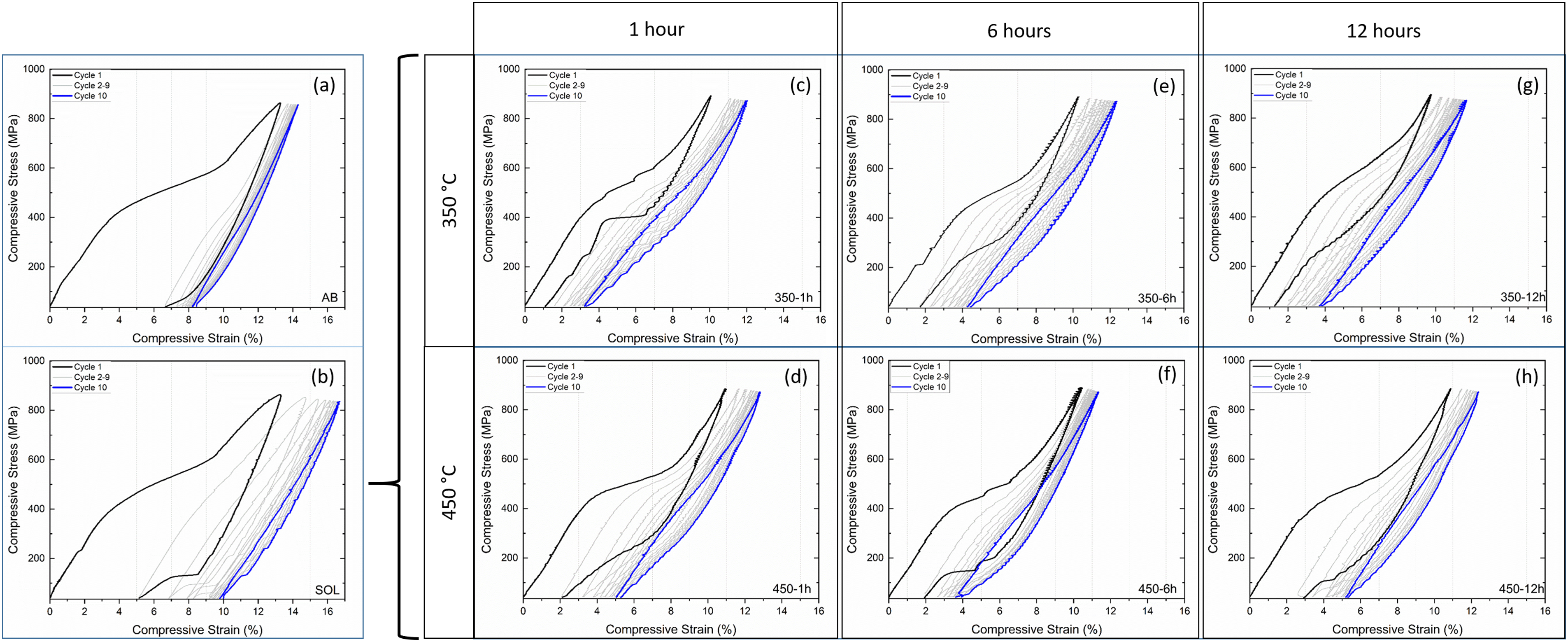
Compression strain curves for (a) as-built (tested at 32 °C), (b) solution treated (31 °C), and aged at (c) 350 °C for 1 h (59 °C), (d) 450 °C for 1 h (66 °C), (e) 350 °C for 6 h (73 °C), (f) 450 °C for 6 h (72 °C), (g) 350 °C for 12 h (80 °C) and (h) 450 °C for 12 h (69 °C).
Comparing the first cycle of all the tested samples in Figure 8, it is observed that the sample in the SOL condition has a more extensive superelastic recovery than that in the AB condition. Nonetheless, this recovery is considered poor for both conditions: after 13.2% of imposed strain, AB recovered 50% of it, whereas SOL was 60%. The ageing treatment shortened the hysteresis of the curves and improved the superelasticity. Comparing the same ageing time at different temperatures, the 350 °C series presents a better mechanical performance after the first cycle. 1 h at 350 °C treatment delivered a sample that returned almost 10% more strain recovery after the first cycle than the sample aged at 450 °C for 1 h. One can notice similar total and recovered strains in both series after 6 h of ageing, leading to comparable permanent deformations. Nonetheless, the differences are emphasized after the ageing time completion. 12 h of heat treatment leads to considerable scenario changes: 350-12 h is less prone to deformation, recovering more strain. Therefore, it ends up in a favourable situation of a less permanent strain than its counterpart 450-12 h. The excellent superelasticity exhibited by the aged samples, especially the 350 °C series, is explained by the precipitation hardening effect. As approached in the previous section, the ageing at 350 °C will produce more and smaller Ni4Ti3 particles than at 450 °C. These coherent particles are mainly responsible for improving the mechanical properties of the matrix, interacting with dislocations, thus hindering its free movement and suppressing the plastic deformation during the superelastic cycles. Consequently, these particles impact superelasticity and strain recovery directly. For enhancing the superelasticity, particles with a smaller radius and homogeneously distributed (350 °C) are preferred over ones with a larger radius, lower in volume fractions with higher interparticle distance (450 °C). In other words, the matrix stabilisation reached by the samples aged at 450 °C after 1 h is not attractive to the mechanical performance improvement since the particles were coarsened from then on. In comparison, at 350 °C, the precipitates are still nucleating and growing. As a result, the 450 °C series presented at the end of the first cycle generally had higher deformation and permanent strains, thus lowered recovered strains.23,53–56 Although logically explainable, transmission electron microscopy (TEM) investigations are required to confirm these assumptions fully. However, TEM analysis was out of the scope of this study.
Based on the results shown in Figure 8, the permanent strain of each sample was calculated for every cycle and displayed the values in Figure 9. The plastic deformation increased as the cycles progressed. AB and SOL samples were deformed to the higher extent (14.3 and 16.6, respectively), attaining the higher permanent strains if compared to the aged samples: 8.4% (AB) and 9.8% (SOL). For each aged series, the best results are 350-1 h and 450-6 h. Both were deformed by over 10%, attaining similar permanent strains when the last cycle finished: 3.3 and 3.8%, respectively. Furthermore, the range of deformation recovery of the cyclic assessment was slightly higher for 350-1 h compared to 450-6 h: 8.7 versus 7.7%. In other words, 350-1 h was more efficient to nearly re-establish its previous dimension despite deforming to a more considerable extent.
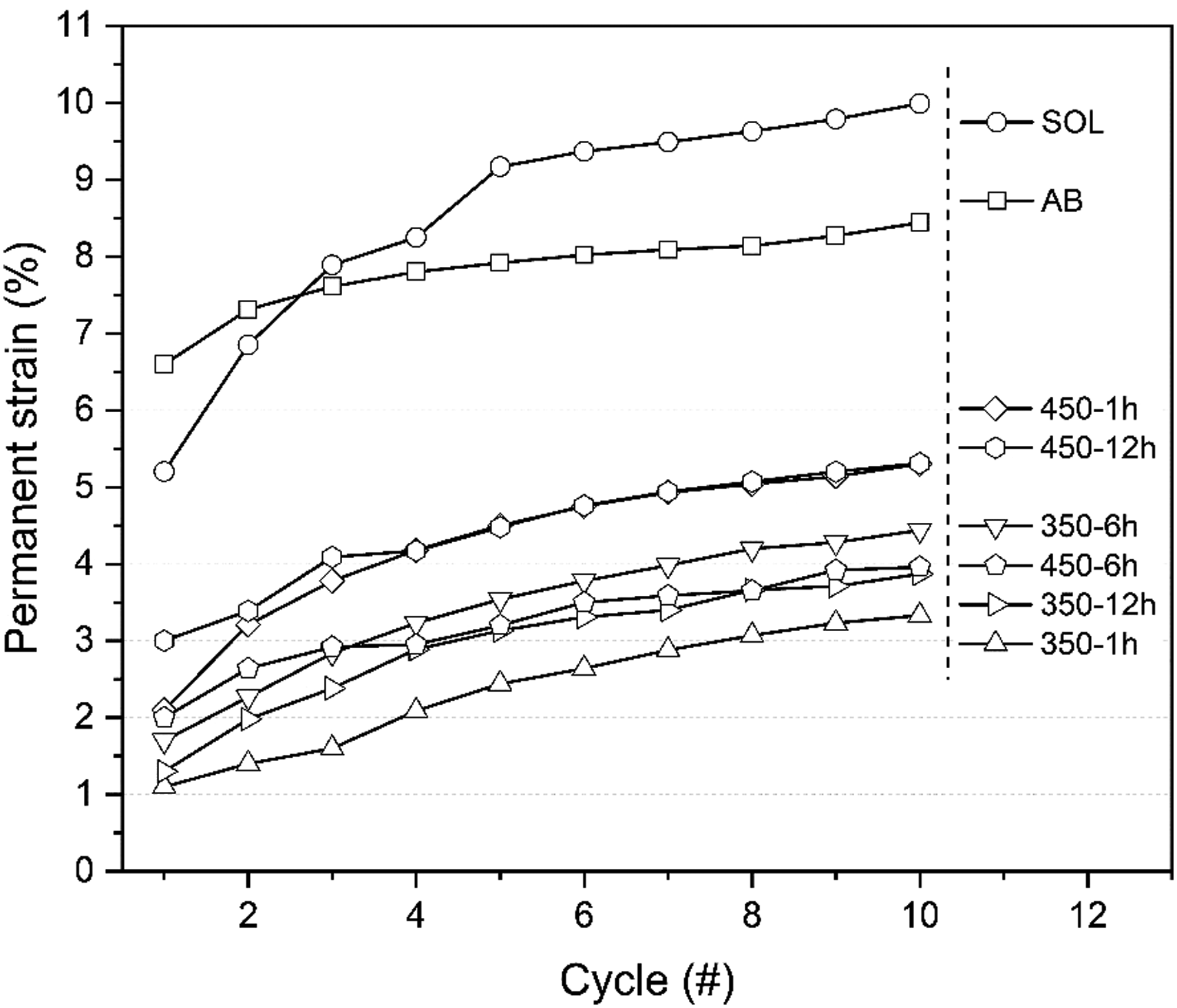
Accumulated residual strain along 10 cycles for EBF3 samples.
A general feature was observed for all samples in Figure 8: the first cycle presented pronounced SIM plateaus, especially in the case of AB and SOL. As the cyclic compression progressed, the hysteresis decreased considerably, followed by barely noticeable plateaus in the 10th cycle. This stabilisation gained along the cyclic assessment – represented by a narrow hysteresis and a single plateau – results from (i) forming microstructural defects such as dislocations, (ii) permanent plastic deformation, and (iii) retained martensitic variants. 57 As more cycles are performed, these stabilisation mechanisms are still operative, reaching a constant value and thus a stable mechanical performance after a certain number of cycles.10,23,47 Therefore, more cycles are required to stabilise 350-1 h and 450-6 h samples. One can confirm that the solution treatment followed by ageing at low temperatures and a short time led to a stable and mechanically functional deposited material.
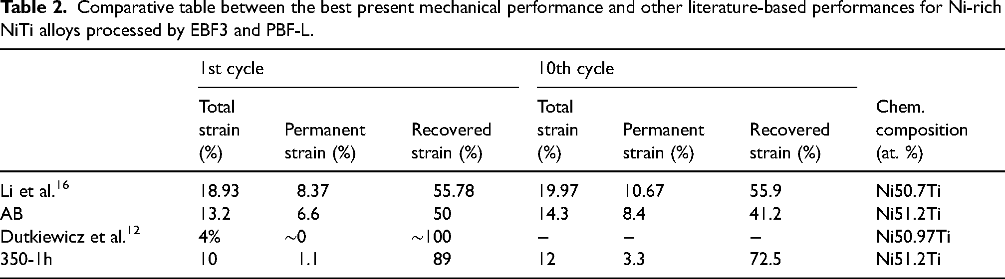
A qualitative comparison of the mechanical response of AB and 350-1 h samples to similar studies of NiTi processed by EBF3 found in the literature (all in compression mode) is in Table 2. Please note that in this work, the values presented in this table are related to true strain and may be comparable to the literature. However, the authors cited in Table 2 did not mention whether the values are related to true or engineering strains. Furthermore, compared to AB, the tests carried out by Li et al. 16 reached a maximum applied stress of 1000 instead of the 840 MPa reached in the present work. Consequently, the total strain values of the present study are smaller than in the literature for the 1st and 10th cycles. Comparing the compression strain curves of both cases (Figure 8(a) and condition B2 in Li's work 16 ), AB transposed the SIM plateau during the tests, whereas the sample produced by Li and colleagues did not. Therefore, more plastic deformation was induced in AB with less recovered strain. Dutkiewicz et al. 12 processed the as-built sample at 500 °C for 2 h. After stressing to 500 MPa one cycle, 4% of total strain was imposed, having a practically null-permanent deformation. Comparing Dutkiewicz et al. 12 findings to 350-1 h, the latter was assessed 2.5 times more deformation at the first cycle, recovering 89% or ∼10% less. Therefore, the present work's results suggest a remarkable functional superelastic behaviour.
Comparative table between the best present mechanical performance and other literature-based performances for Ni-rich NiTi alloys processed by EBF3 and PBF-L.
Summary and conclusions
In the present study, it was possible to clarify the importance of heat treatment to improve the mechanical/functional properties of EBF3-manufactured NiTi parts. Ideally, these fabricated parts should present high-strain recoveries after the cyclic stabilisation in the as-built state, thus eliminating the need for further costly and time-demanding secondary operations. However, due to the complexity of the EBF3 process (thermal history) and the metallurgical behaviour of NiTi under these processing conditions, the as-built condition presented poor mechanical performance. It was shown that the precipitation of Ni4Ti3 particles is essential to improve the functional response of the as-built condition. As a result, the EBF3 parts reached functional properties comparable to state-of-art research by applying heat treatment.12,16
From the microstructural point of view, the solution treatment could not entirely dissolve Ti2Ni particles or Ti-rich eutectic phases. Nonetheless, this treatment could reduce the inhomogeneity in the matrix although its negative impact on the superelastic performance.
It can be concluded that ageing treatment was essential to improve the superelastic properties. By precipitating Ni4Ti3, a multistage B2 ↔ R ↔ B19’ transformation was observed for 350 °C and 450 °C aged samples. Despite the differences in the precipitation kinetics and thermodynamic equilibrium of the precipitation behaviour, both treatment temperatures benefitted the superelastic performance. The recovered cycled strain of 350 °C and 450 °C aged samples attained a remarkable 72.5% (350-1 h) and 68.1% (450-6 h), presenting low permanent strains (3.3% and 3.6%, respectively) when considering the high levels of total strain adopted during mechanical testing. More cycles are required to reach a permanent strain accumulation and thus stabilisation of strain during the mechanical assessment. Further studies will focus on producing almost fully recoverable parts after post-processing heat treatments. Overall, this work showed the importance of post-heat treatment on near-net shape EBF3 fabricated parts and its beneficial effects on improving the superelastic properties.
Footnotes
Acknowledgements
The authors gratefully acknowledge financial support from the Austrian aviation program ‘TAKE-OFF’, the Austrian Ministry for Climate Action, Environment, Energy, Mobility, Innovation and Technology BMK, and the CD-Laboratory for Design of High-Performance Alloys by Thermomechanical Processing from Christian Doppler Forschungsgesellschaft.
Declaration of conflicting interests
The author(s) declared no potential conflicts of interest with respect to the research, authorship, and/or publication of this article.
Funding
The author(s) disclosed receipt of the following financial support for the research, authorship, and/or publication of this article: This work was supported by the Österreichische Forschungsförderungsgesellschaft.