
Abstract
In today’s world, researchers are actively seeking the most suitable materials to meet the growing industrial demands. These materials need to possess specific characteristics such as lightweight nature, high strength, excellent mechanical properties, and environmental friendliness. Due to these requirements, relying solely on mono fiber composite materials is insufficient. Therefore, it has become necessary to incorporate different reinforcements into polymer matrices to achieve the desired mechanical properties. This study focuses on the fabrication of a novel hybrid composite using jute fibers, luffa fibers, palmyra leaf fibers, and AISI 303 (0.5 mm) wire mesh combined with epoxy resin. The fabrication process involved utilizing vacuum bagging techniques. To assess the mechanical properties of the hybrid composites, two wire mesh orientations (45° and 90°) and a total of 12 stacking sequences of jute/wire mesh/luffa/palmyra (J/W/L/P) were selected. The mechanical characterization of the hybrid composites included tensile, impact, flexural, and interlaminar strength tests. Furthermore, a dynamic mechanical analyzer (DMA-8000) was employed to investigate the elastic behavior, including storage modulus (E′), loss modulus (E″), and damping factor (tan δ). Additionally, the fracture surface's microstructure was examined using a scanning electron microscope (SEM). Among the various stacking sequences and fiber orientations, the 45° fiber orientation and the stacking sequences JWLP, JLWP, JWPL, JPWL, PWJL, and PJWL exhibited superior ultimate tensile strength. Notably, the PWJL stacking sequence displayed the highest average tensile strength (74.83 MPa), flexural strength (131.60 MPa), percentage elongation (1.35%), and interlaminar strength (1.47 kN). Moreover, dynamic mechanical analysis revealed that the hybrid composite sample with 90° wire mesh orientation exhibited a peak energy absorption of 0.820 at the transition region, specifically at a frequency of 0.5 Hz.
Keywords
Introduction
Over the past few decades, there has been a significant increase in the utilization of composite materials within the engineering industry. This surge can be attributed to the growing demand for cost-effective, eco-friendly materials that possess high specific mechanical properties. 1 Composite materials come in various forms, including metal matrix composites, polymer matrix composites, and ceramic matrix composites, each offering distinct advantages over traditional engineering materials. 2 These composites exhibit specific mechanical properties that make them suitable alternatives in numerous applications.
In the present socio-engineering era, there is a widespread search for materials that are eco-friendly, bio-degradable, cost-effective, and possess variable and high specific mechanical properties. A notable outcome of continuous innovation in this field is the natural fiber-reinforced hybrid composite, which is steadily replacing conventional synthetic fiber composites. This transition is driven by the desire to overcome the negative impacts associated with synthetic composites and effectively meet the demands of the socio-engineering landscape. 3 The natural fiber-based hybrid composite finds applications in diverse industries such as construction, aerospace, automobile, marine, and more. Its popularity stems from the cost-effectiveness, high efficiency, and eco-friendliness of the resulting products.4,5 Among these industries, the automotive sector particularly benefits from the use of natural fiber-reinforced hybrid composites. This type of composite successfully addresses the current challenges related to fuel efficiency, emission regulations, aesthetic appearance, and most importantly, cost-effectiveness. Furthermore, consumers are increasingly seeking vehicles that offer an appealing aesthetic look, superior quality, safety, and affordability.6–9
Extensive scientific research is underway to enhance the thermal, mechanical, acoustic, viscoelastic, vibration, magnetic, and machining properties of natural fiber-based hybrid composites, aiming to fulfill the existing demand.10–15 The versatility of natural fiber composites allows for their fabrication in various forms, including plates, sheets, channels, pipes, boxes, and beams, to cater to present requirements. 16 It's important to note that the fabrication process itself has a significant impact on the properties of natural fiber composites. Several techniques are employed in the fabrication of these composites, including injection molding, compression molding, hand lay-up, film stacking, filament winding, vacuum bagging, and pultrusion, among others. 17
There are various chemical treatments available for fibers, with alkali treatment being the most widely used. However, other treatments hold specific significance. Chemical treatment plays a vital role in enhancing the quality of fibers by eliminating pectin, hemicellulose, and lignin, thereby transforming them from hydrophilic to hydrophobic. This treatment improves the adhesion between the fibers and the matrix, ultimately enhancing the overall fiber quality.18–20 The use of natural fiber bio-composites as an ideal alternative to combat pollution and non-biodegradability issues has gained significant attention. The consideration of chemical and enzymatic treatments of fibers makes them superior to conventionally used materials in the automotive industry. 21
The vacuum bagging technique is a well-known fabrication method used to minimize voids or air entrapment within composites. This technique ensures a cleaner and improved fiber-to-resin ratio, while also allowing for economical resin usage, resulting in consistent resin application. 22 Despite the implementation of these various techniques, hybridization proves to be better suited to meet the needs of the industrial sector. Hybrid composites offer advantages such as high strength/weight ratio, low cost, lightweight properties, and the ability to absorb vibrations without compromising the structural integrity of the composite. Resins are the preferred choice for developing natural fiber composites due to their low shrinkage, cost-effectiveness, non-toxicity, and high strength characteristics. 23
Studies have demonstrated that hybrid composites incorporating four types of natural date palm tree fibers (DPTFs) can enhance the strength and damping capability of adhesive joints in quasi-static and impact loading conditions. Furthermore, the effects of natural DPTFs on the mode II fracture energy of E-glass/epoxy plain-woven laminated composites indicate that the inclusion of petiole and bunch fibers at the same percentage leads to different fracture toughness results. Optimal addition of nanoparticles significantly enhances the mechanical properties of hybrid composites, particularly in preventing crack propagation under various loading conditions.24–26
Extensive literature on natural fibers like jute, palmyra, and luffa confirms their suitability for commercial production of hybrid composites, effectively meeting industry requirements.27–29 Single-layered natural fiber composites exhibit relatively lower mechanical characteristics compared to multi-layered hybrid composites utilizing different natural fibers. The fiber orientation within individual single-layered composites has a significant impact on the overall mechanical properties. The stacking sequence of multi-layered hybrid composites greatly enhances the achievement of favorable dynamic mechanical properties that cannot be attained by single-layered composites alone.30–33
Chemical treatment of jute fibers improves their storage modulus (E′), loss modulus (E″), and damping (tan δ) properties. The storage and loss moduli increase with surface modification of the fibers through chemical treatment. Additionally, the superior adhesion between fibers and matrix contributes to the superior viscoelastic properties of hybrid composites. The glass transition temperature also increases with higher fiber loading, emphasizing the positive influence of fiber loading and surface modification on dynamic mechanical properties, ultimately leading to stronger fiber-matrix adhesion.34–38
Upon conducting an extensive literature survey, it was observed that there is limited research available on natural fiber-based hybrid composites reinforced with wire mesh, specifically regarding the evaluation of their dynamic mechanical behavior. Among the existing studies, the investigation of jute fiber-reinforced composites with wire mesh exhibited particularly interesting findings related to dynamic mechanical behavior. 39 However, considering all the aforementioned parameters, the authors were motivated to develop epoxy-based hybrid composites using natural fibers (jute, luffa, and palmyra leaf) reinforced with wire mesh, targeting applications in the automotive and industrial sectors. The fabrication process involved various considerations, including chemical treatment of fibers, fiber orientation, and stacking sequence, to achieve the desired hybrid composite. Subsequently, experimental evaluations were conducted to analyze the viscoelastic behavior, encompassing storage modulus, loss modulus, and damping factor, using a dynamic mechanical analyzer (DMA). The mechanical characterization encompassed tensile, impact, flexural, and interlaminar properties. To gain insights into the interaction between fibers/wire mesh and the matrix, fractured surfaces were examined using a scanning electron microscope (SEM). In addition to the mechanical properties, the water absorption behavior of the fabricated hybrid composite was investigated to assess its performance under real environmental conditions. The aim of this comprehensive study was to explore the potential of the developed hybrid composite for practical applications, considering its dynamic behavior, mechanical properties, and environmental durability.
Experimental details
Materials
The materials used in the fabrication of the hybrid composites are:
Fibers material Matrix material Chemicals Miscellaneous items
Fibers material
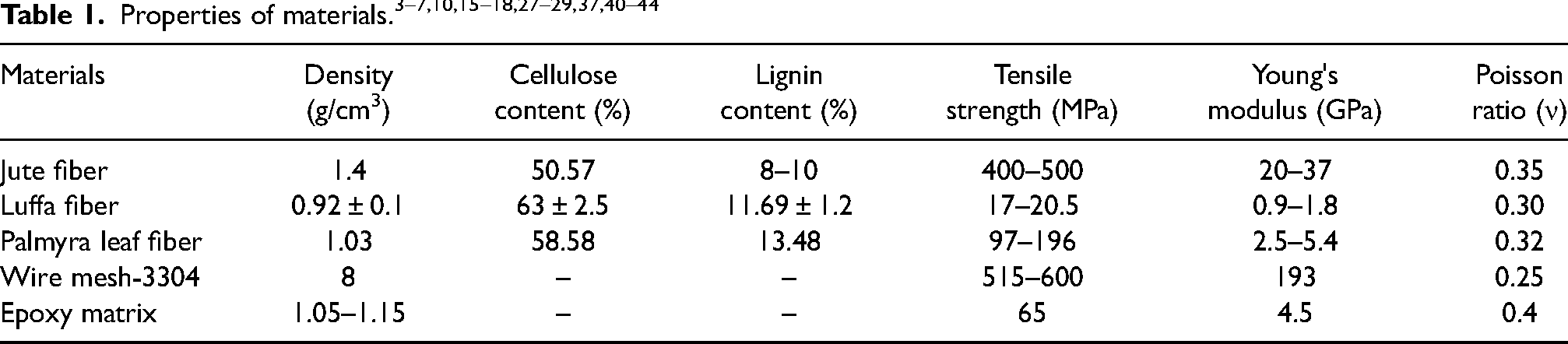
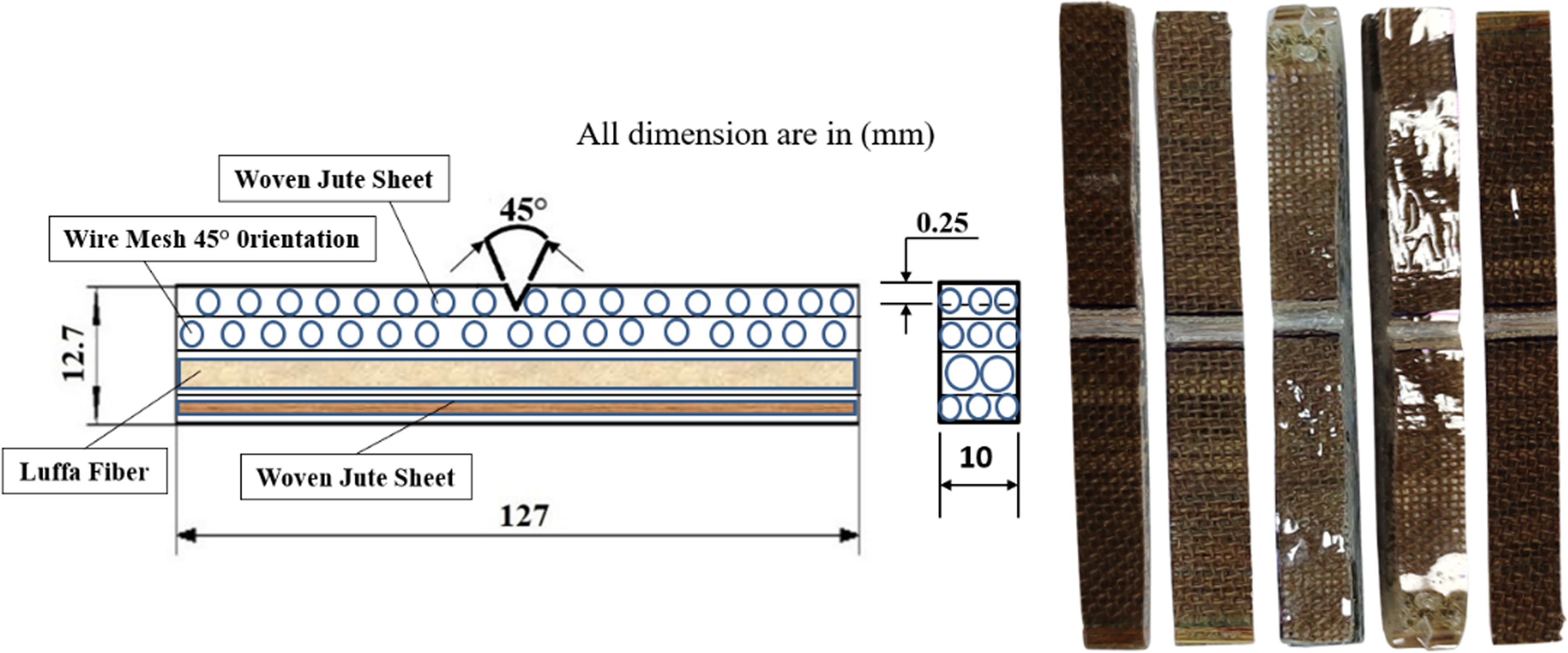
Fibers typically serve as the reinforcing phase in composite materials. The fabrication of the current hybrid composites involves the use of natural fibers, specifically woven jute, luffa, and palmyra leaf, along with SS304 wire mesh, as illustrated in Figure 1. Jute fiber belongs to the Corchorus capsularis family, luffa fiber belongs to the Cucurbitaceae family, and palmyra fiber belongs to the Borassus flabellifer family. These three types of fibers are readily available in Asian countries. The SS304 wire mesh is utilized during fabrication and is positioned between the layers of natural fibers. The properties of these components are listed in Table 1.
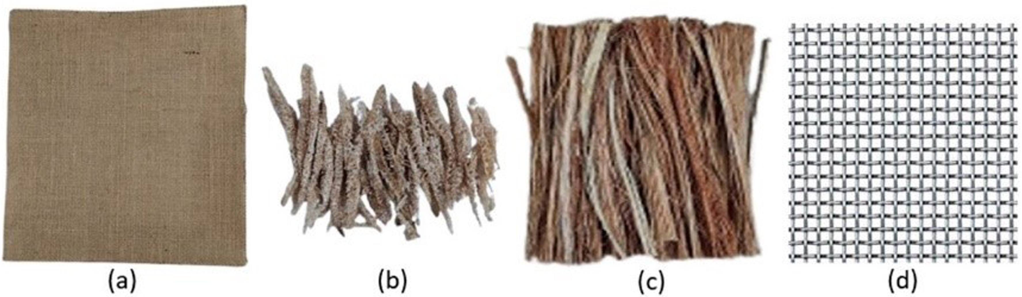
Fibers: (a) woven jute, (b) luffa, (c) palmyra leaf and (d) wire mesh.
Matrix material
Various types of material matrices, such as metals, ceramics, and polymers, are utilized in composite materials. Among these options, polymer matrices are the most commonly employed. This preference can be attributed to their cost-effectiveness, ability to facilitate the fabrication of intricate parts with minimal tooling costs, and excellent properties at room temperature compared to metal and ceramic matrices. In the fabrication process of the hybrid composite, epoxy resin 520 is utilized, accompanied by an 18% concentration of hardener. The epoxy resin and hardener were procured from CF Composites in Delhi.
Chemicals
During the fabrication process of the hybrid composite, certain chemicals such as acetic acid, sodium hydroxide (NaOH), and distilled water are employed. The natural fibers undergo an alkali chemical treatment, which involves the removal of hydroxyl groups and lignin from the fiber surface. This treatment renders the fiber surface hydrophobic and rough, thereby enhancing its bonding capabilities with the matrix material. To prepare the chemical solution for the alkali treatment of the fibers, the required concentration of NaOH is mixed with water.
Miscellaneous items
During the fabrication process of the composite, various supporting materials are used, such as scissors, adhesive tape, plastic film, a rectangular wooden stick with a finished surface, breather fabric, vacuum film, peel ply fabric, perforated release film, sealant tape, and more. These materials play a crucial role in ensuring the successful construction of the composite structure.
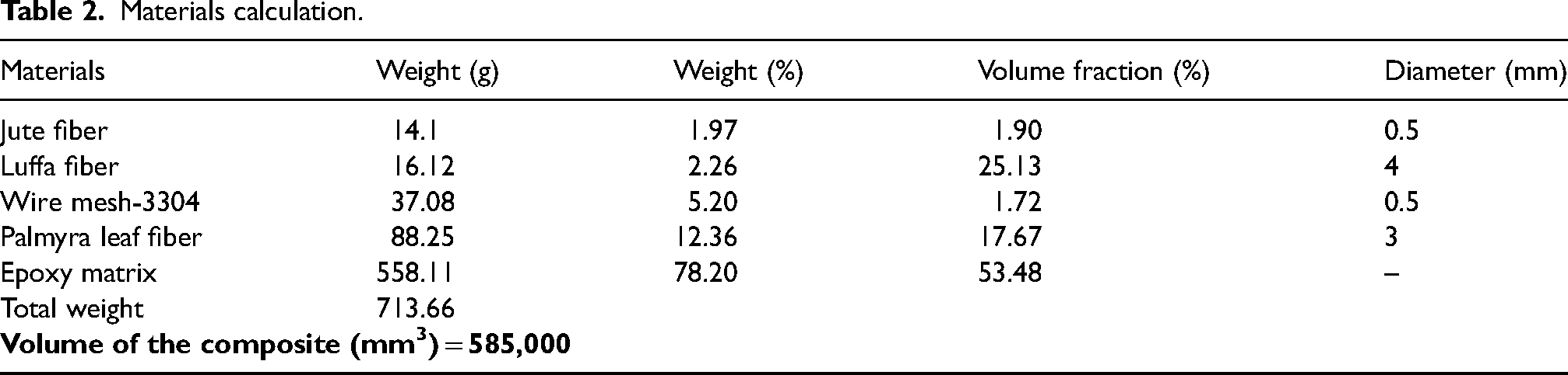
The properties of the materials and material calculation are shown in Tables 1 and 2, respectively, for fabrication of hybrid composite.
Materials calculation.
Methodology
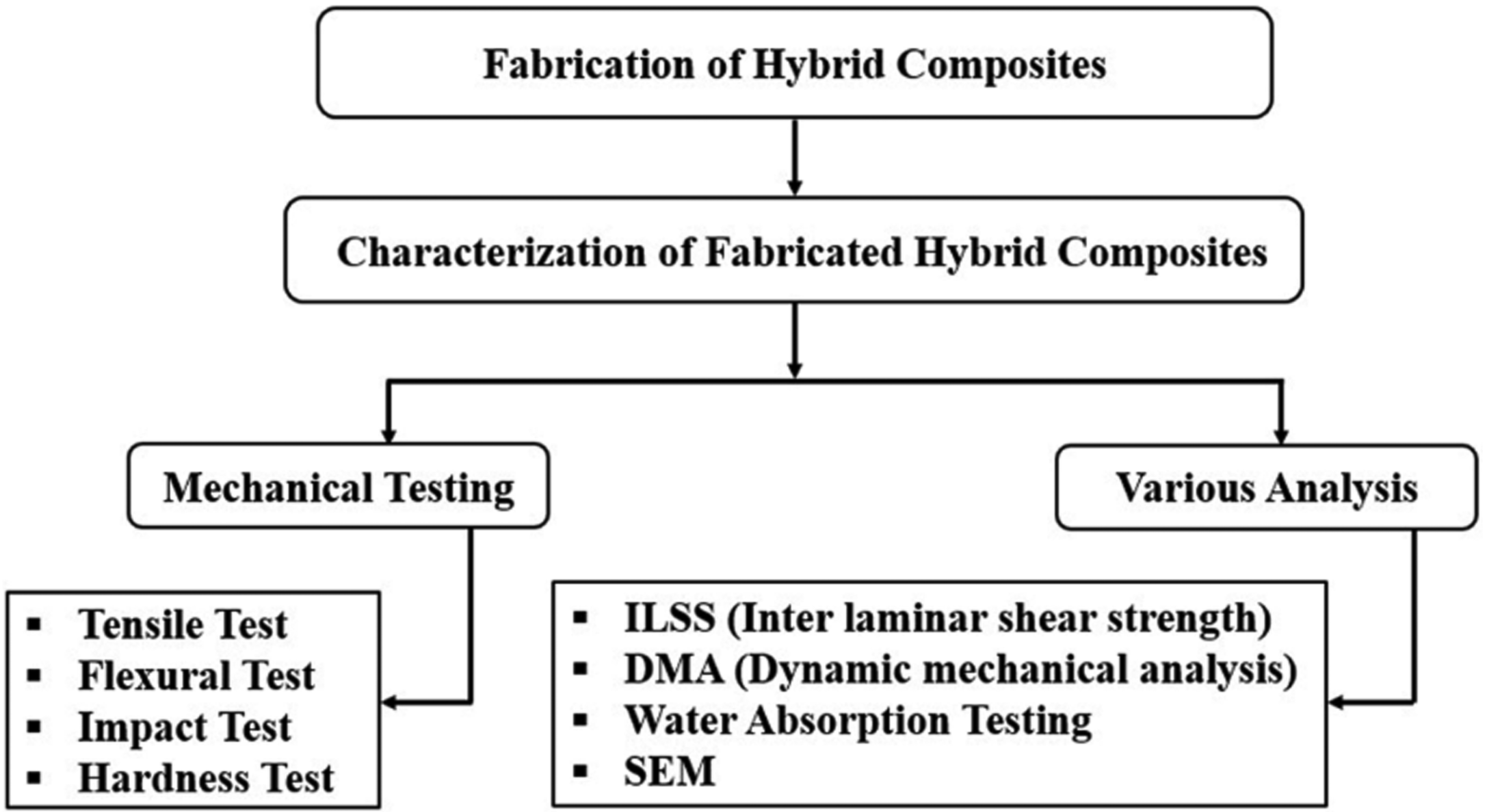
Fabrication and characterization of the hybrid composites are listed in the sequential flow diagram in Figure 2.
Systematic flowchart of the procedure.
Alkali treatment of fibers
Before commencing the fabrication of the hybrid composites, a chemical treatment was performed on the natural fibers (jute, luffa, and palmyra). In this study, alkali (NaOH) treatment was carried out using distilled water. For the palmyra fibers, a solution of 4% NaOH and 96% water was utilized at a temperature of 90°C for 60 minutes to achieve optimal fiber results. 45 Jute fibers were treated with a solution of 2% NaOH and 98% water for 24 hours to obtain the best outcomes, 46 while luffa fibers underwent a treatment with a solution of 5% NaOH and 95% water for 4 hours. 47 Throughout each fiber treatment process, the solution was swirled at regular intervals. After the completion of each treatment, the fibers were removed and thoroughly rinsed with distilled water to remove lignin, wax, hemicellulose, and impurities. To neutralize the alkaline effect on the fibers, acetic acid was added to the rinsing water. The rinsing process continued until the pH value of the water reached 7, typically requiring two to three cycles. Once the water attained a pH value of 7, it indicated the completion of the fiber treatment process. Finally, the fibers were left to air dry for 48 hours, followed by drying in an oven at 70°C for 6 hours.
Design and fabrication of mold frame
To fabricate the hybrid composite, a handmade mold frame was constructed in the advanced composite lab using a rectangular wooden stick, adhesive tape, and a 200-micron A4 plastic sheet. The wooden mold frame was attached to the plastic sheet to ensure affordability and facilitate easy removal of the composite after fabrication. The dimensions of the mold cavity were (260 × 225 × 10) mm3, as illustrated in Figure 3.
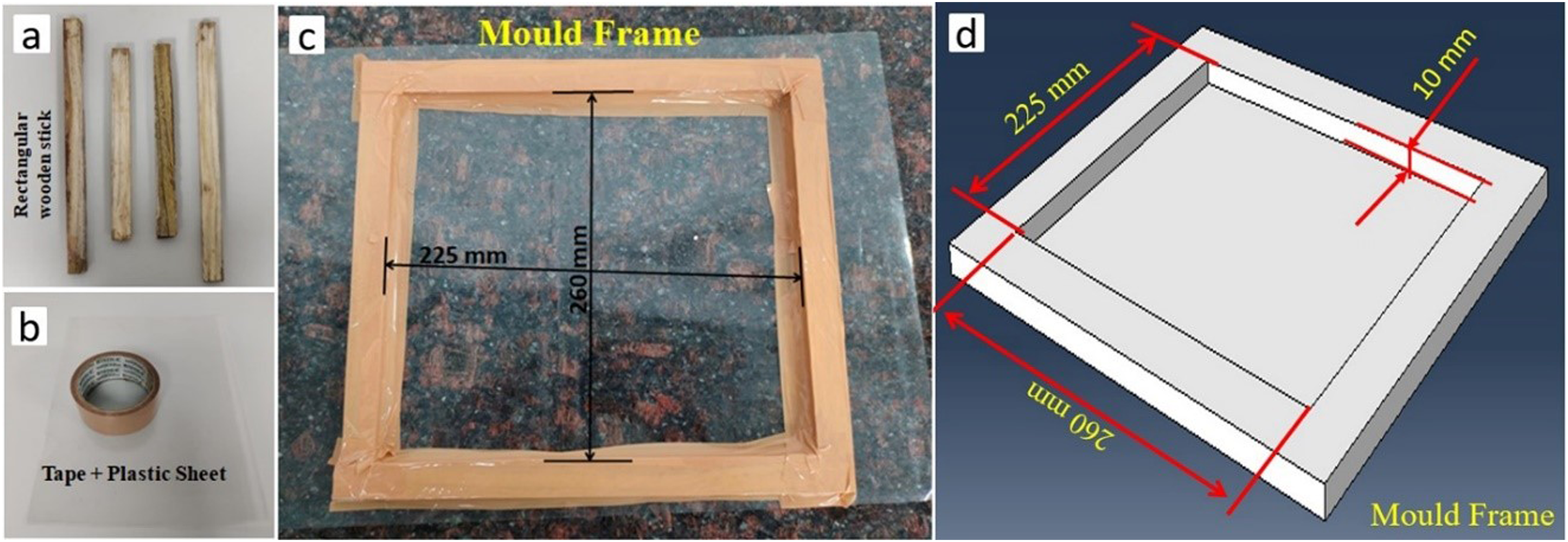
(a) Rectangular wooden sticks, (b) adhesive tape and plastic sheet and (c, d) mold frame cavity and design.
Fabrication of hybrid composites and preparation of samples
The fabrication of the hybrid composite material for the current investigation has been successfully completed. The fabrication process involved the combination of hand layup and vacuum bagging techniques to enhance the quality of the composite compared to using the hand layup method alone. A mold cavity with dimensions of 225 × 260 × 10 mm was used for composite fabrication, utilizing a wooden frame mold plate as shown in Figure 3. To prevent adhesion between the mold frame and the composites, a release film was applied to the mold surface.
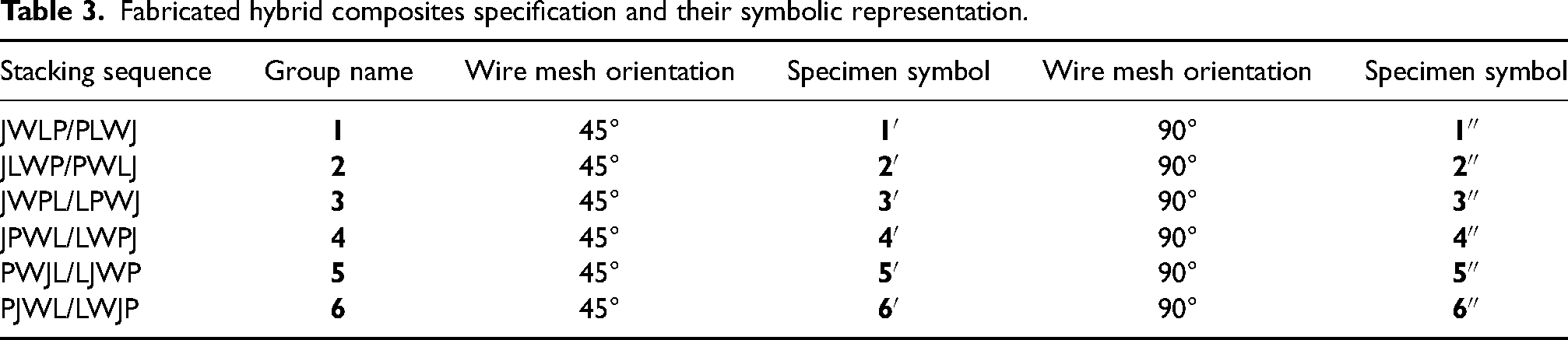
The Palmyra, luffa, wire mesh, and woven jute sheets were prepared according to the size of the mold cavity. The fibers were cut to fit the dimensions of the mold frame cavity. The woven jute and SS304 wire mesh were cut to a dimension of (225 × 260) mm2, while the Palmyra and Luffa fibers were chopped to a length of 260 mm. For the fabrication of the hybrid composites, four layers of fibers (jute, luffa, wire mesh, and Palmyra) were used, and six different stacking sequences were employed, including 45° and 90° wire mesh orientations. This resulted in a total of 12 different types of fabricated composites. The specifications of the fabricated hybrid composites and their corresponding symbolic representations, based on the different fiber stacking sequences and wire mesh orientations, are summarized in Table 3.
Fabricated hybrid composites specification and their symbolic representation.
The fabrication processes for two random hybrid composites, labeled as 1′ and 1″, are illustrated in Figure 4(d). These processes involve using alkali-treated and sized fibers along with 90° and 45° wire mesh orientations. The fibers, including palmyra, luffa, wire mesh, and jute sheet, are layered in the mold frame, with each layer being accompanied by the appropriate mixture of epoxy resin and hardener in a ratio of 10:1.8. A hand roller is used to ensure uniform mixing and spreading of the matrix material at each layer of fibers and resin. Detailed material calculations for the fabrication of any group of samples can be found in Table 2. Once the layering and resin application are complete, the vacuum bagging process is initiated. This process involves enveloping the mold with a perforated release film, followed by the application of peel ply fabric and breather fabric. The entire unit is then enclosed within a sealed vacuum film, with a vacuum suction unit positioned at one of the corners, as depicted in Figure 4(c). A negative pressure of 5 bar is applied through the suction operation.
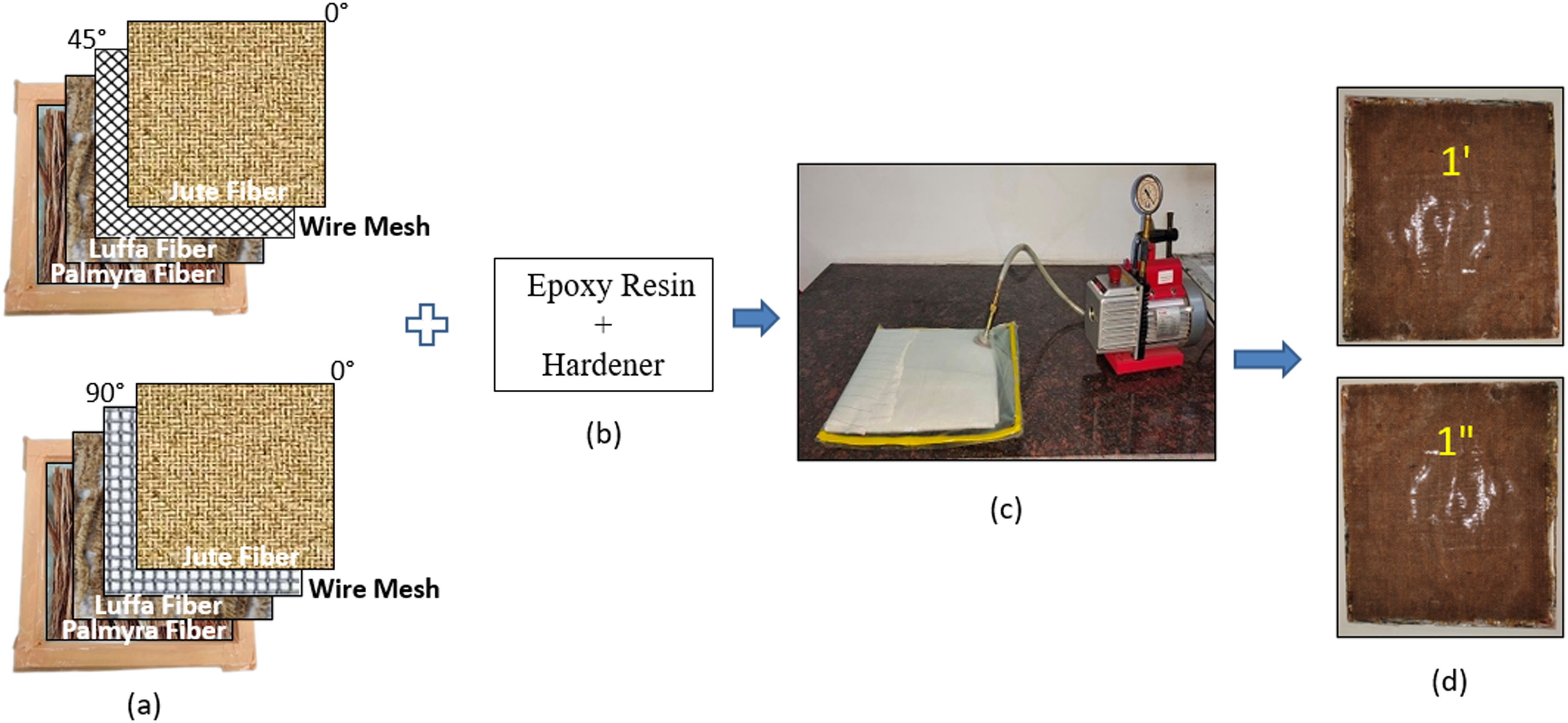
Fabrication process: (a) fibers stacking, (b) matrix material, (c) vacuum bagging and (d) fabricated composites.
After the vacuum is applied, the composite is left to cure at room temperature for a duration of 48 hours. This fabrication process is employed for all six groups of samples. A summarized depiction of the fabrication process for group 1 hybrid composites is presented in Figure 4. The samples are prepared according to the dimensions specified in the ASTM standards. To determine various mechanical properties, the composites are cut to their respective standard test sample dimensions. Before cutting the samples, a marked layout is prepared to optimize material usage. The cutting operation is performed using a CNC milling machine. A 5-mm diameter high-speed steel (HSS) end mill cutter is utilized to achieve the desired specimen dimensions.
Characterization of hybrid composites/test set-up
Tensile testing
The tensile test specimen was prepared according to the ASTM D638-03 standard. The schematic diagram of the tensile test specimen is illustrated in Figure 5. The specimen had an overall thickness of 10 mm and a gauge length of 57 mm. Tensile testing was conducted using an Instron 3382 Model universal testing machine. The sample dimensions were 165 mm × 29 mm, and a strain rate of 5 mm/min was applied. The test specimen was clamped between the jaws of the testing machine's clamping arrangement, and an axial tension force was applied until it fractured.
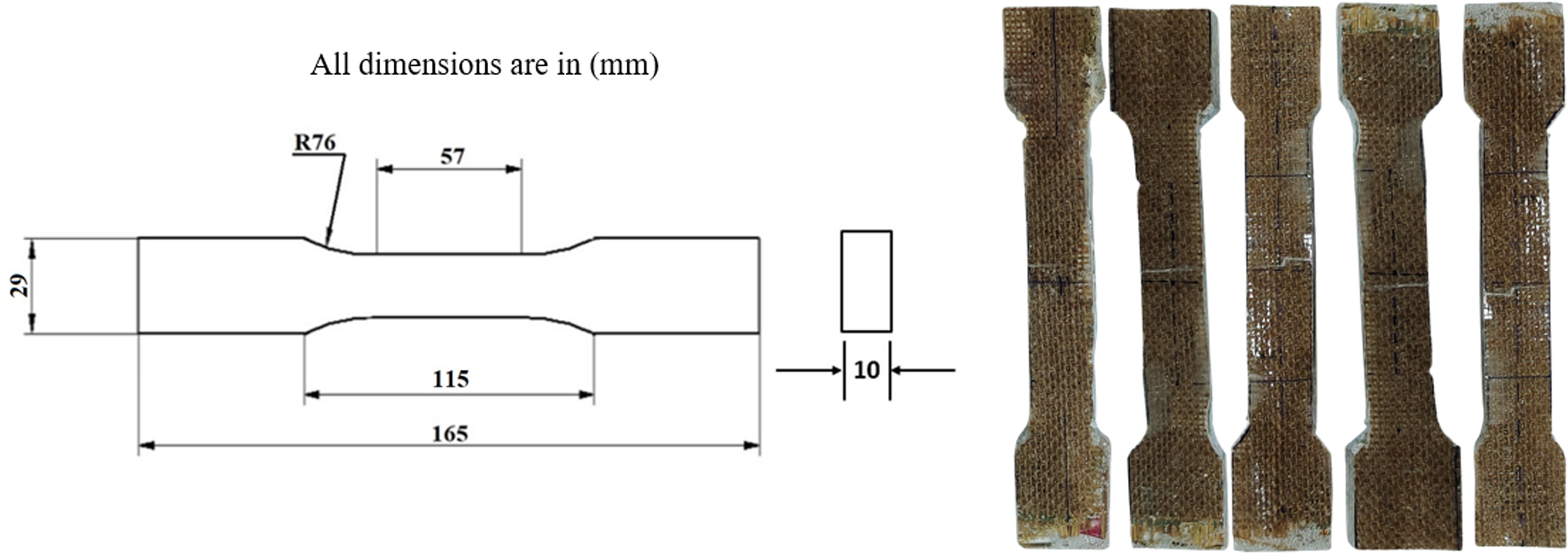
Tensile test specimens.
The strain value was determined by dividing the change in length (ΔL) by the original length (L) of the specimen. Mathematically, strain is represented by the symbol ε, and it can be expressed as ε = ΔL/L. The universal testing machine (Instron-3382) used in this study was equipped with axial extensometers, which provided the strain data. The extensometer setup involved attaching the knife edges of the extensometer to both ends of the specimen’s gauge length. It measured the displacement in length when a load was applied and the specimen was pulled apart by the crosshead. For this experiment, the average value of five samples was taken for each stacking sequence and wire mesh orientation.
Flexural testing
ASTM standard D790 was employed for conducting flexural testing (3-point bend test) on the hybrid composite. The specimen had a length of 210 mm and a width of 12.7 mm. A span length of 70 mm was selected between the supports for each sample. The schematic diagram of the flexural test sample is shown in Figure 6. The bending rate used for this testing was 1 mm/min. The flexural test was performed on the same machine, Instron 3382 model, utilizing the flexural test attachment. Five identical samples were tested for each stacking sequence and wire mesh orientation, and the average values were used for analysis. The flexural strength and flexural strain were calculated using equations (1) and (2), respectively.

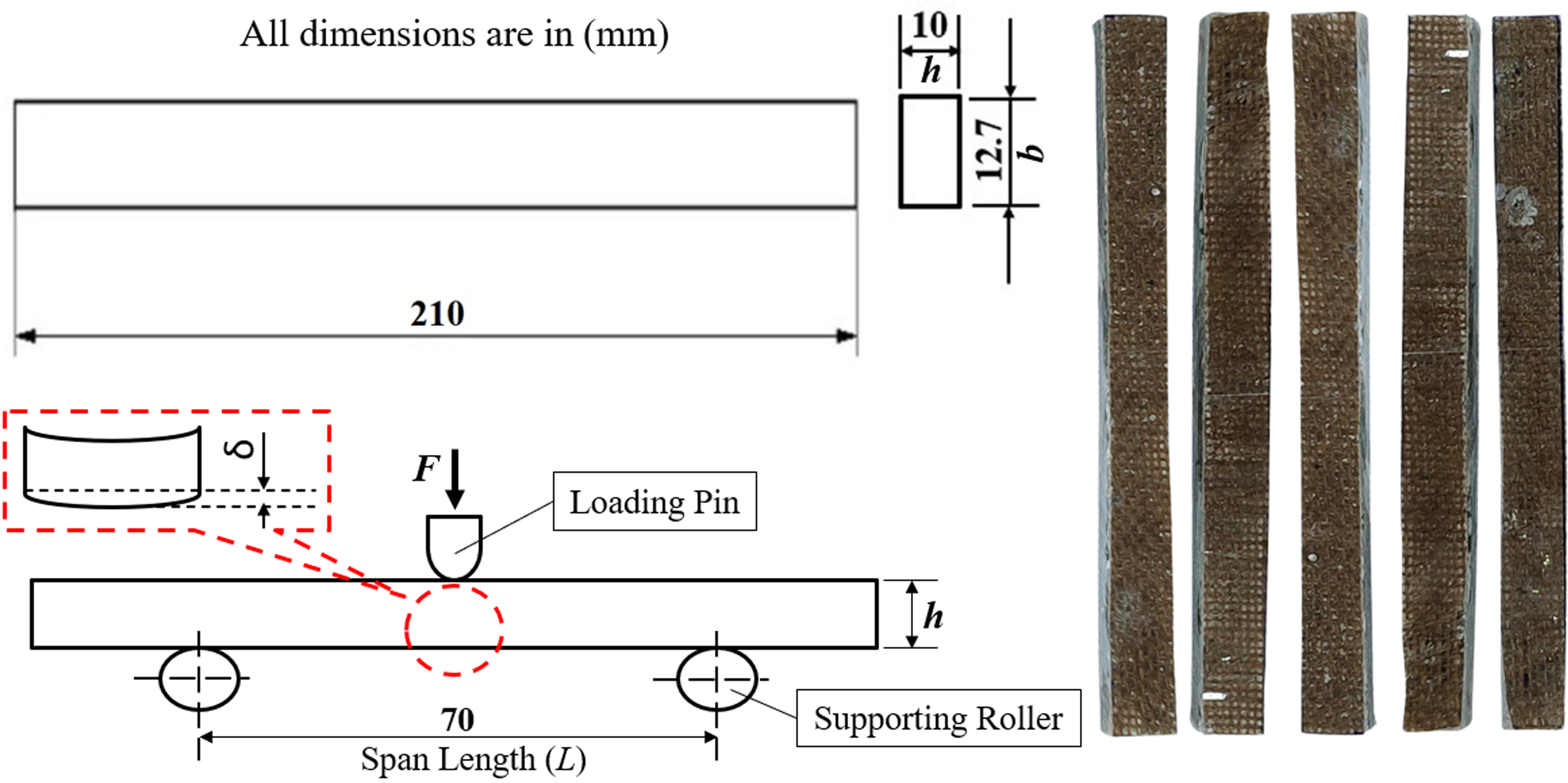
Flexural test specimens.
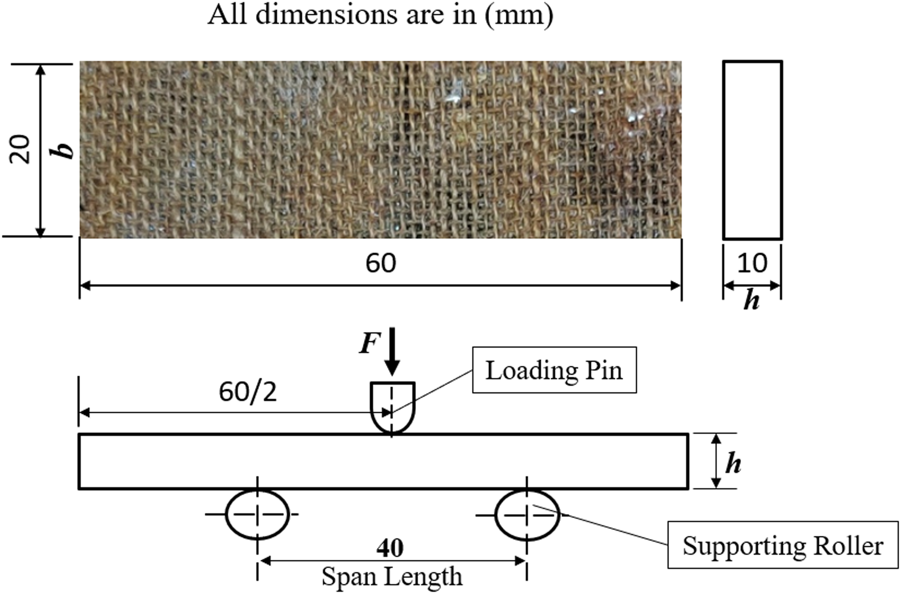
Impact testing
The impact strength of the fabricated hybrid composites was determined using the Charpy test. The ASTM D256 standard was followed, and an IT-30 digital Charpy pendulum impact tester was used for the test. The samples were prepared accordingly, as shown in Figure 7. A V-shaped notch with a cut angle of 45 ± 5° was created in the middle of the samples using the edge of a flat file. This V-shaped notch creates a high stress concentration, which reduces the energy required to initiate fracture. Essentially, the measured total energy required for the samples to break is the energy required for failure propagation. During the test, the specimen was placed in a vice with the V-shaped notch facing away from the direction of the hammer blow. The pendulum’s speed of 3.46 m/s was recorded during the test. An impact hammer with a mass of 13.75 ± 0.25 kg and an initial impact energy of 5.5 J was used for the samples with wire mesh orientations of 45° and 90°. For each composite sample group, five specimens (each with a size of 127 × 12.7 mm × thickness) were considered, and the mean results were reported accordingly.
Impact test specimens.
Hardness testing
To determine the hardness of the fabricated samples, hardness testing was conducted following the ASTM E10-18 standard. A rectangular piece with dimensions of 50 × 50 mm was prepared for this purpose, as shown in Figure 8. The sample was gripped by the optical Brinell hardness testing machine (Model-M/S Samarth Engineering), which had a gripper diameter suitable for the test. The machine used was semi-automatic, and a load of 3000 kg was applied with a 10-mm diameter indenter ball. Indentations were made on both the top and back surfaces of the specimen, and the average hardness value was obtained in terms of Brinell hardness number (BHN).
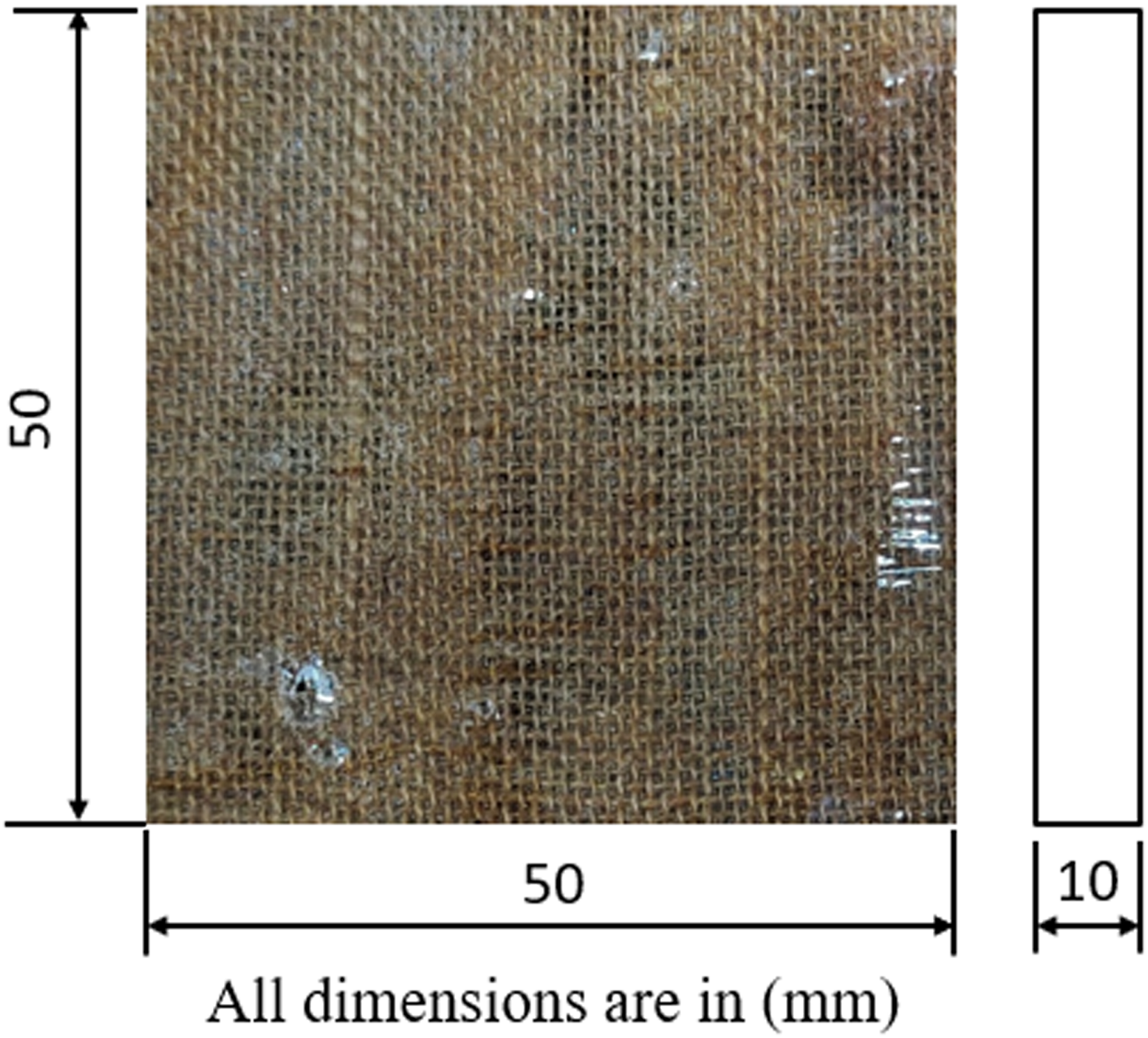
Hardness testing sample.
Interlaminar shear strength
The interlaminar shear strength (ILSS) of the fabricated hybrid composites was evaluated following the ASTM D2344 standard. The ILSS test, also known as the short beam strength test, was conducted. The test specimen dimensions are illustrated in Figure 9. To calculate the ILSS, the following expression, as given in equation (3), was used.
Short beam strength testing sample.
Five samples from each composite group were tested, and the average value was calculated. The Instron 3382 machine was used for this testing, maintaining a constant loading speed of 1 mm/min. The ILSS was determined using the Jurawski formula (equation 3). According to the Jurawski calculation, 48 the midpoint of the span experiences the highest interlaminar shear stress during a three-point bend test over a rectangular section.
Dynamic mechanical analysis
The dynamic mechanical characteristics of the fabricated hybrid composites were analyzed using the Perkin Elmer dynamic mechanical analysis (DMA)-8000. The DMA study covered the rubbery, transitional, and glassy regions. Specimens were prepared following the ASTM D5023 standard, with dimensions of 50 mm × 13 mm × 3 mm. The storage modulus (E′), loss modulus (E″), and damping factor (δ) were measured as a function of frequency and time. The experimental testing involved a heating rate of 2°C/min, a temperature range of 20–200°C, and an operating frequency range of 0.5–5.0 Hz. The storage modulus (E′) provides an estimate of stiffness, which is an important parameter for engineering materials that require energy storage capabilities under varying loading conditions. The viscoelastic behavior of fiber matrix epoxy composites is affected by temperature increases due to their elastic nature. Maximum energy dissipation occurs in the transition region, which is represented by the loss modulus (E″).
Water absorption
There is significant concern regarding the susceptibility of natural fiber polymer composites to moisture absorption when used in outdoor environments.
49
Although natural fiber-based hybrid composites offer numerous advantages, water absorption is one of the drawbacks of these fabricated composites.
50
The test specimens were prepared in accordance with the ASTM D570 standard, as depicted in Figure 10(a). A study was conducted to determine the maximum percentage of water absorption for the manufactured hybrid composites. Both the samples with 45° and 90° wire mesh orientations were completely immersed for 15 days in three different types of water: distilled, normal, and salty, as illustrated in Figure 10(b). After 15 days, the samples were removed and the surface was dried with a dry cotton cloth before weighing. This process was repeated at intervals of 15, 30, 45, 60, 75, 90, and 105 days. The water absorption percentage was calculated using the following equation (4).
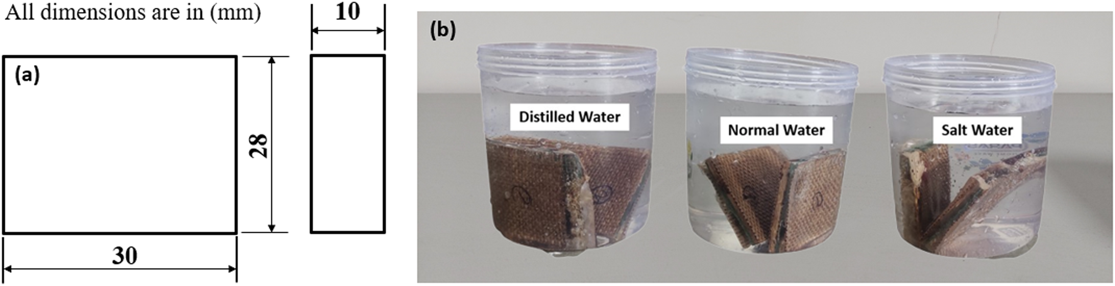
Water absorption: (a) test sample dimension (mm) and (b) samples immersed in different water condition.
Where W1 and W2 represent the specimen’s weight (in grams) before and after being submerged in water, respectively.
Scanning electron microscopic analysis
To obtain a clear view of the microstructure, the composite specimens were thoroughly cleaned to remove any dust particles. A fine coating of conductive gold plating was then applied to each specimen using the plates provided with the SEM machine. This gold plating enables the capture of high-quality images. The fracture surfaces and microstructures of the test samples were examined using a Carl ZEISS-EVO MA15 SEM with a 15-kV accelerating voltage. The SEM images of the hybrid composite were captured at various magnifications (50×, 100×, 150×, and 250×). These images reveal the presence of cracked wire mesh, fiber pull-out, fiber fracture, fiber-epoxy matrix, and voids in different locations within the composite.
Result and discussion
Tensile properties
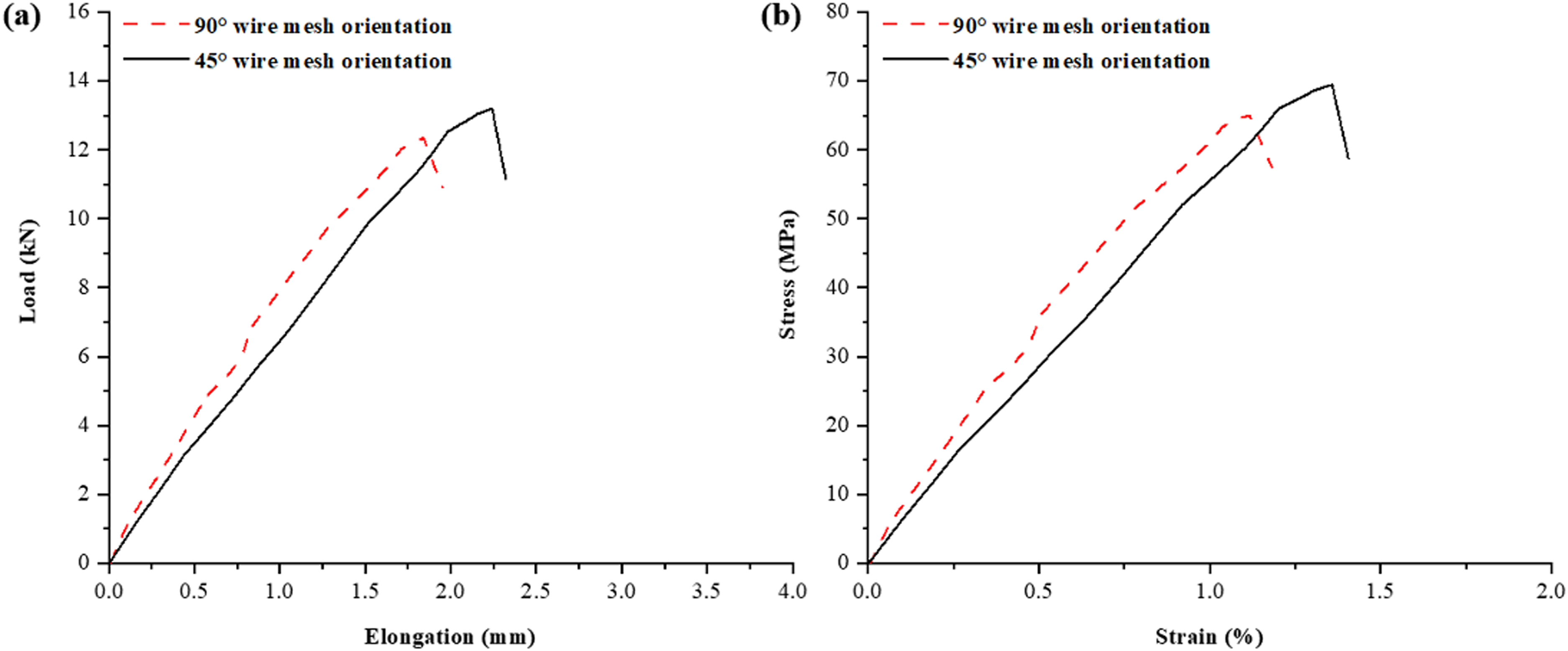
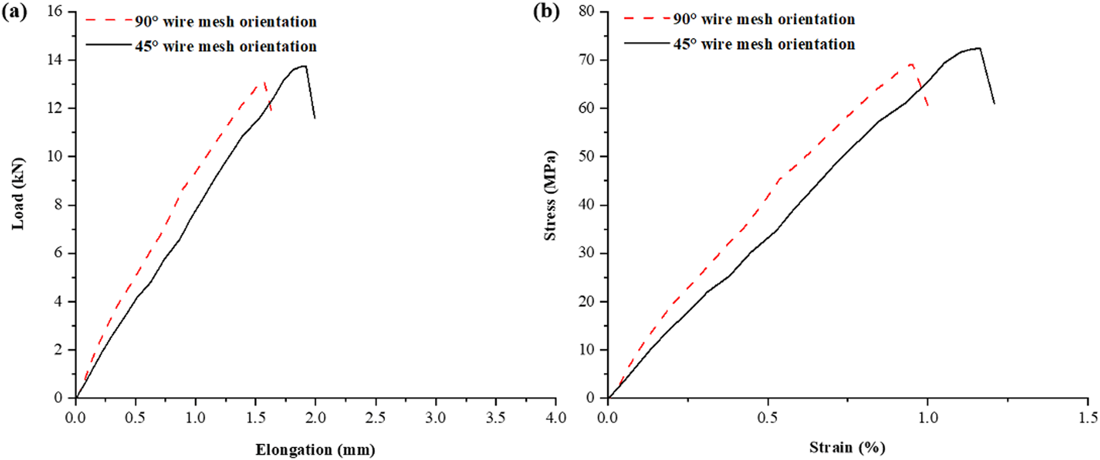
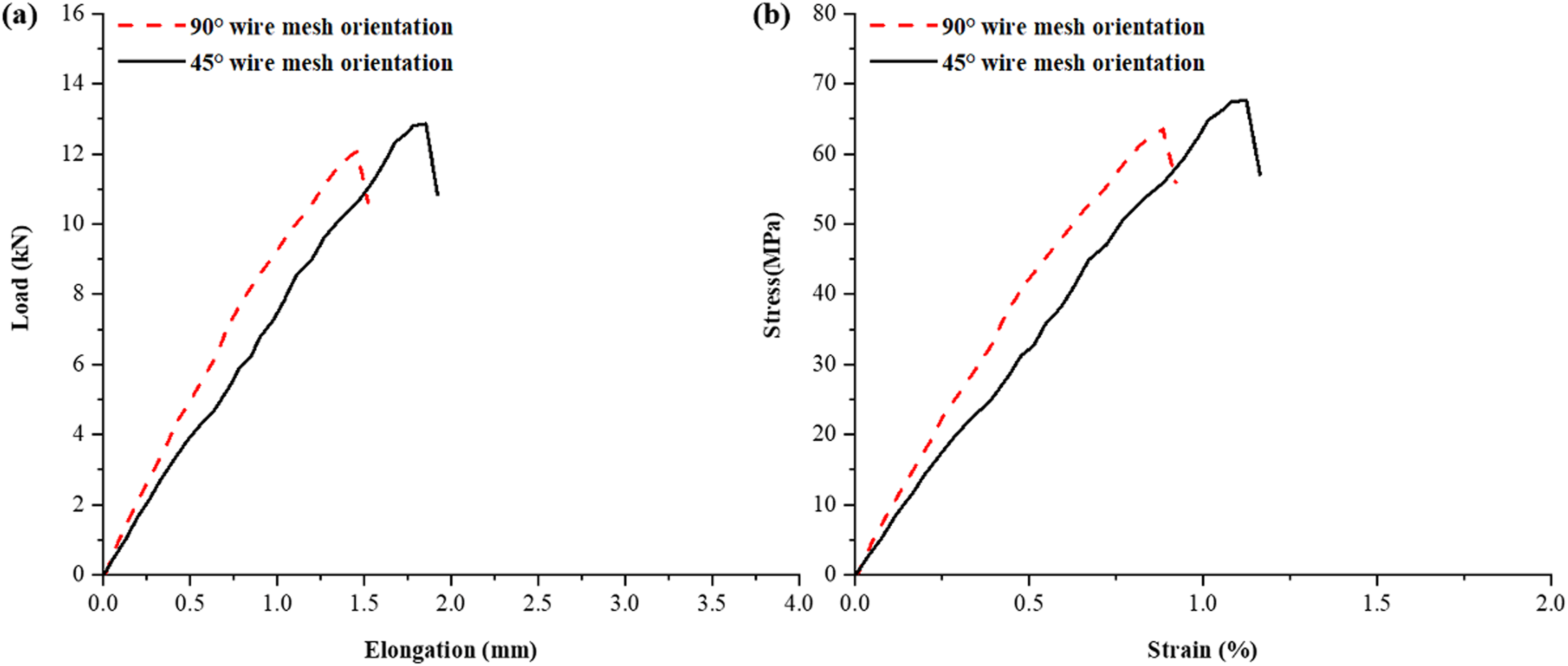
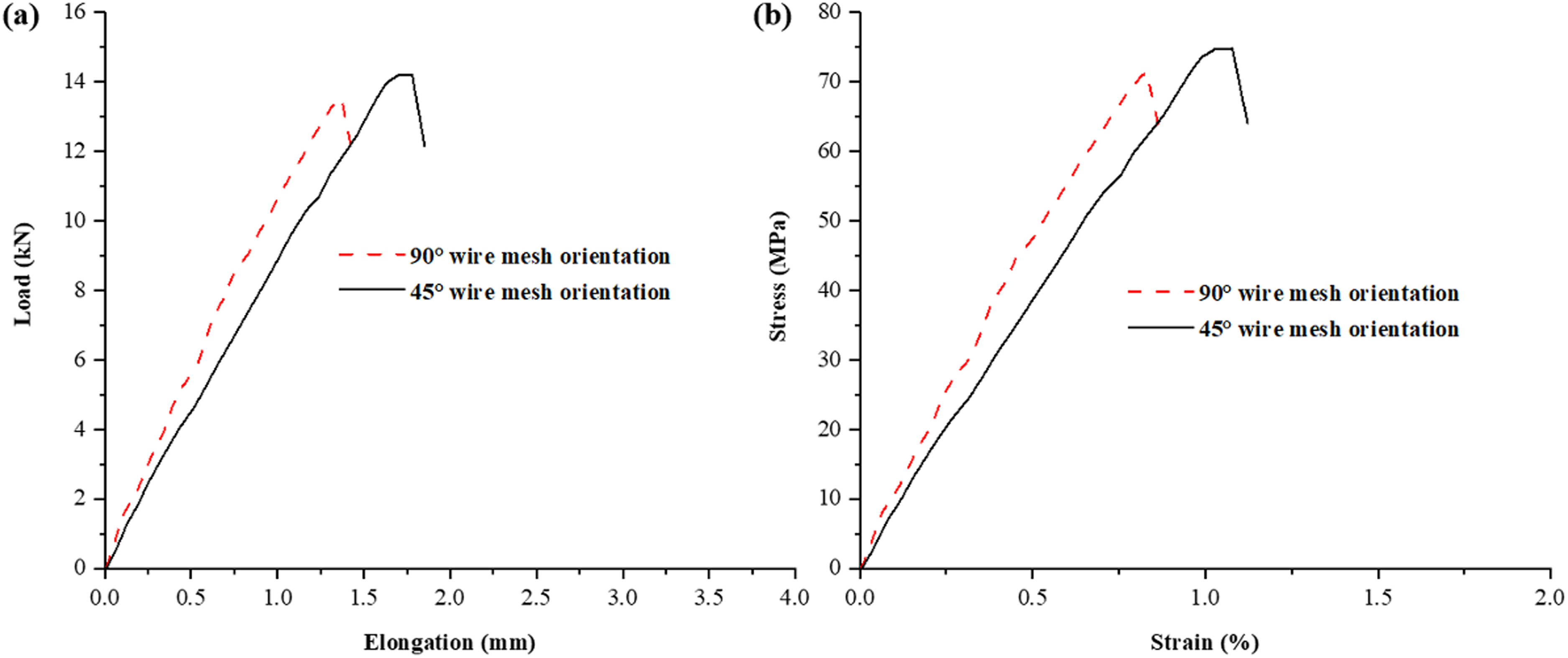
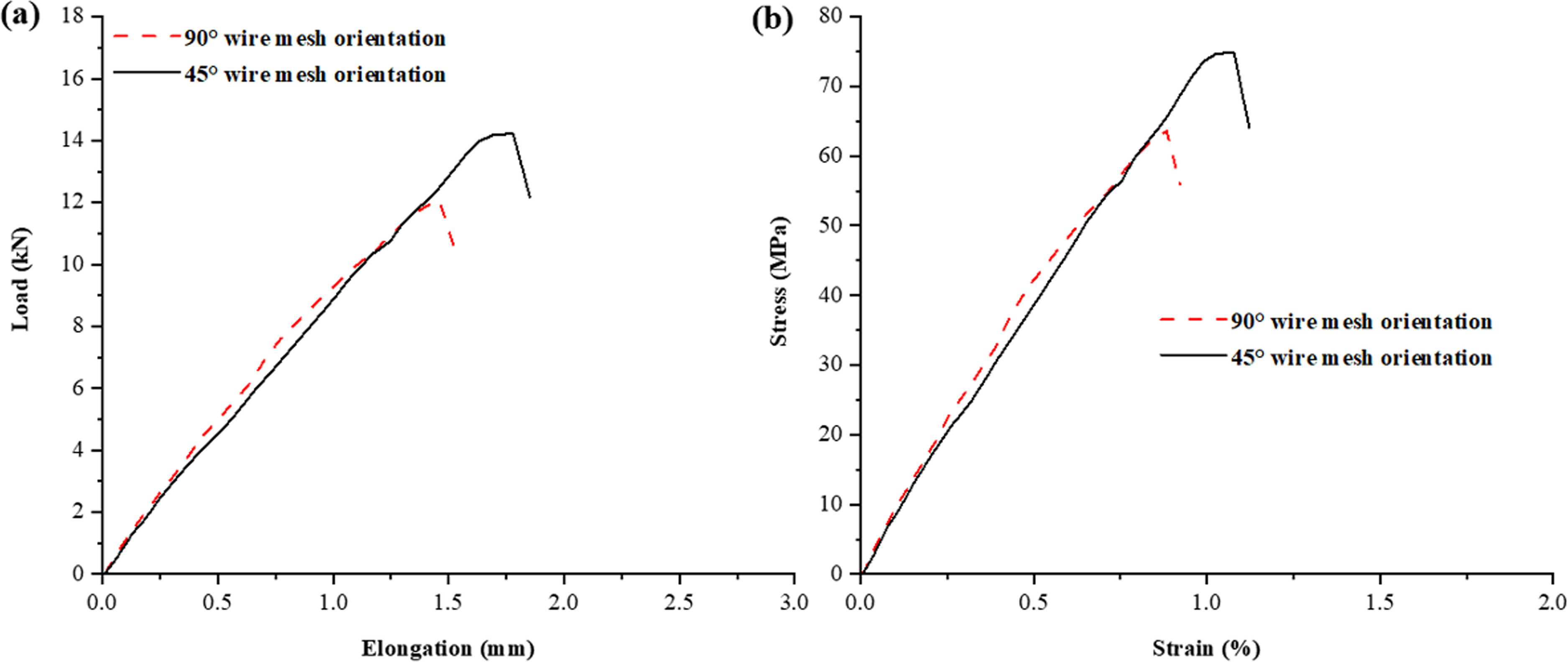
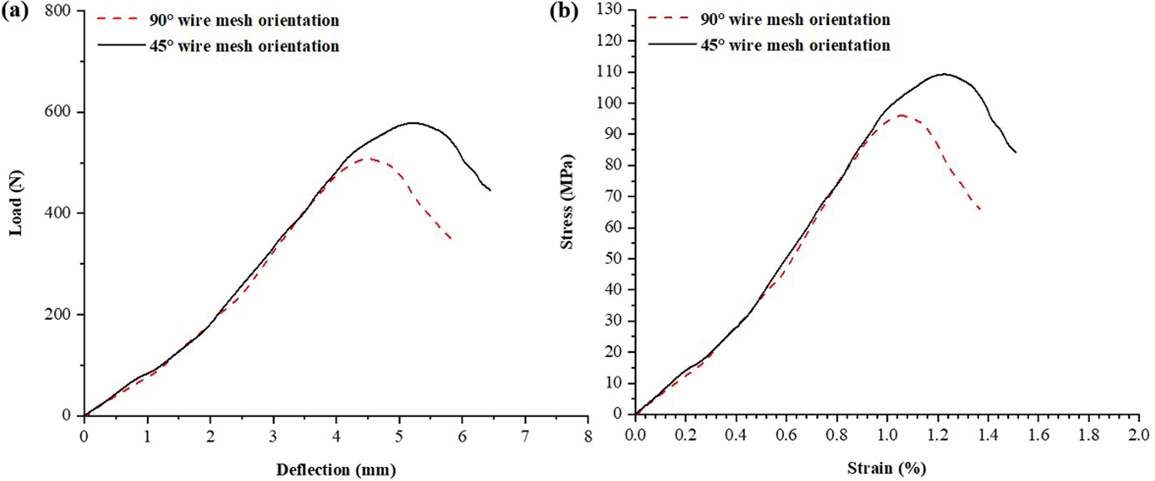
The stress–strain diagram provides valuable information for calculating a material’s yield strength (YS). Based on the experimental data obtained, the load versus elongation and stress versus strain plots are presented for six pairs of hybrid composites with two distinct orientations of wire mesh reinforcement. These plots are shown in Figures 11 to 16. Additionally, Table 4 displays the YS, percentage of elongation, and ultimate tensile strength (UTS) values for the 12 different stacking sequences of hybrid composites, considering the two distinct orientations of the wire mesh reinforcement.

Tensile strength of group sample-1: (a) load vs elongation diagram; (b) stress vs strain diagram.
Tensile strength of group sample-2: (a) load vs elongation diagram; (b) stress vs strain diagram.
Tensile strength of group sample-3: (a) load vs elongation diagram; (b) stress vs strain diagram.
Tensile strength of group sample-4: (a) load vs elongation diagram; (b) stress vs strain diagram.
Tensile strength of group sample-5: (a) load vs elongation diagram; (b) stress vs strain diagram.
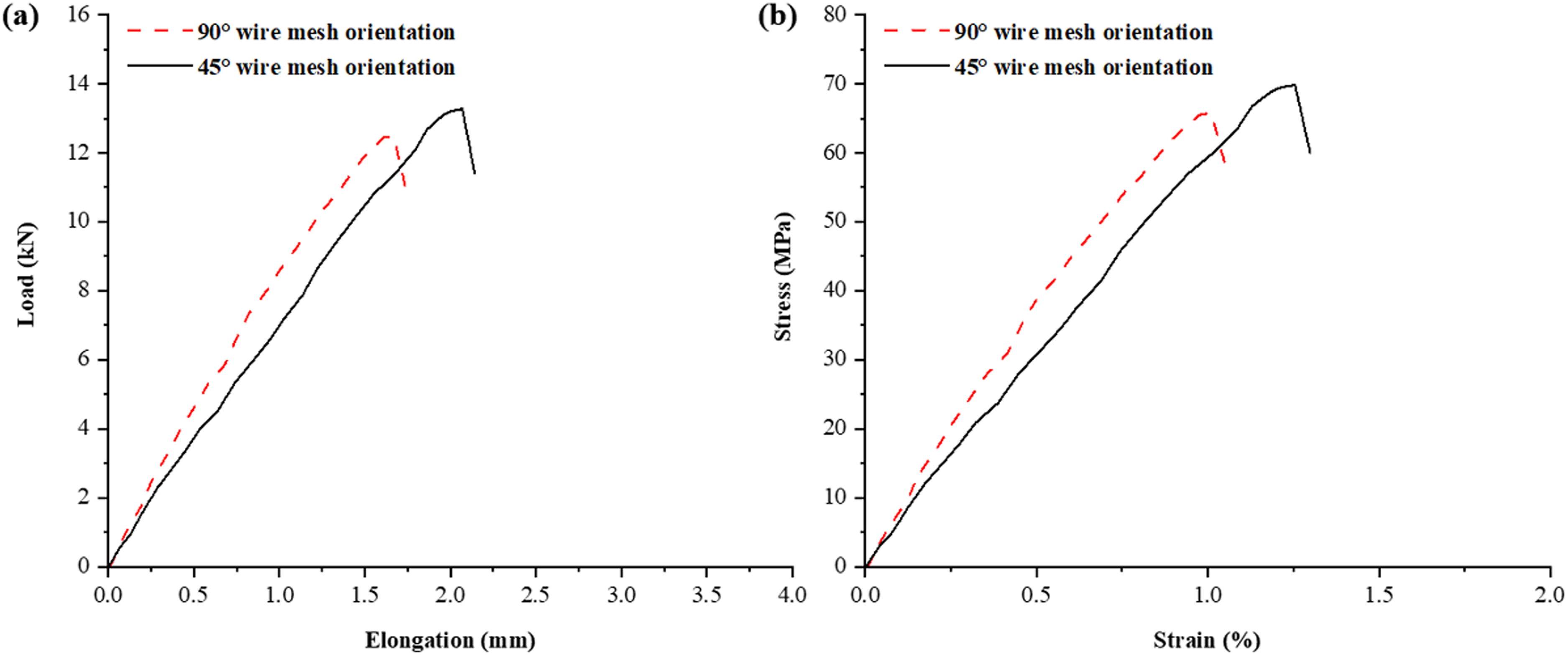
Tensile strength of group sample-6: (a) load vs elongation diagram; (b) stress vs strain diagram.
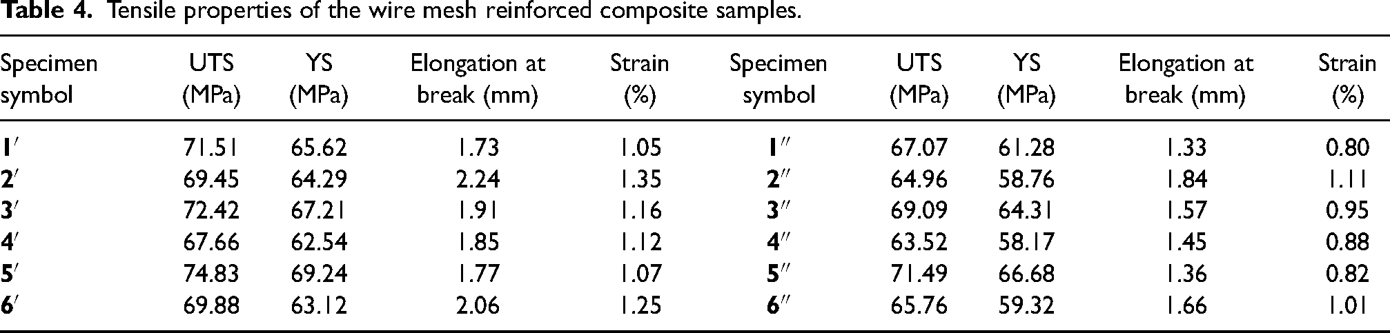
Tensile properties of the wire mesh reinforced composite samples.
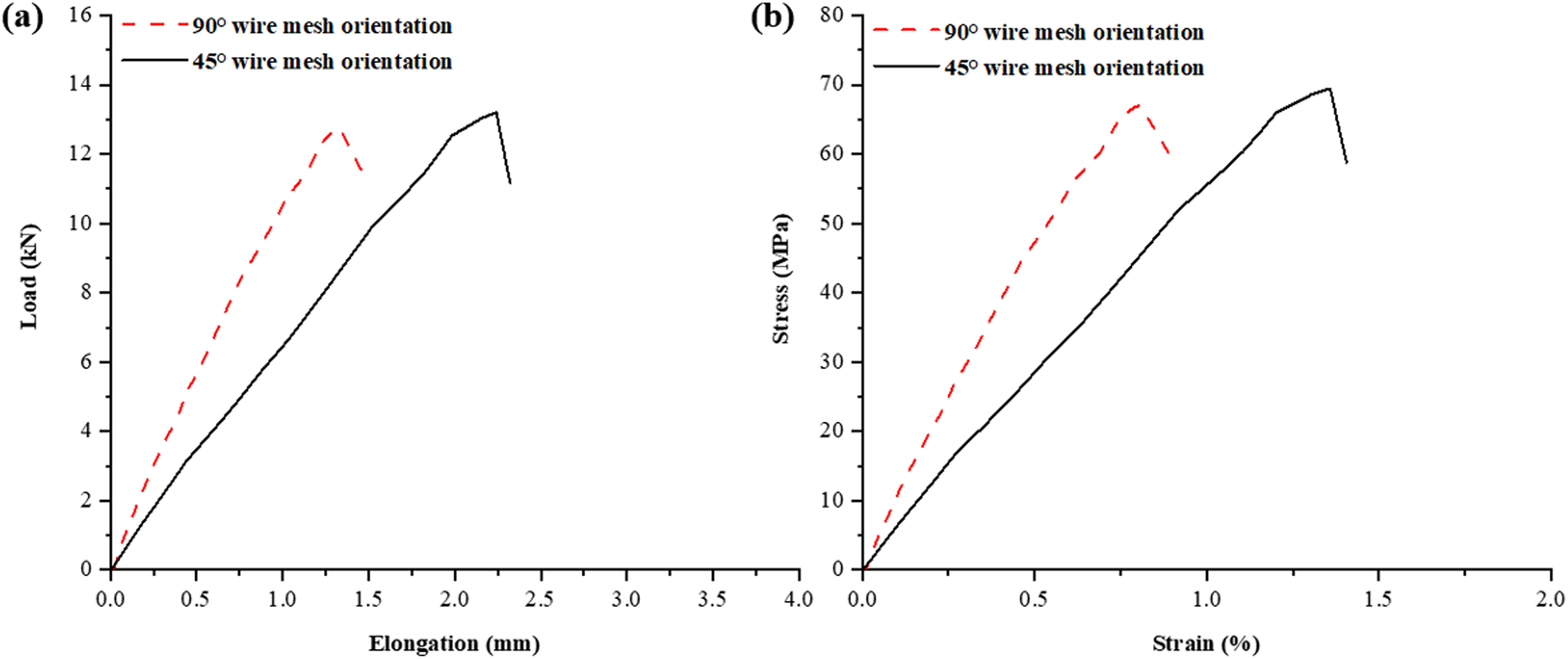
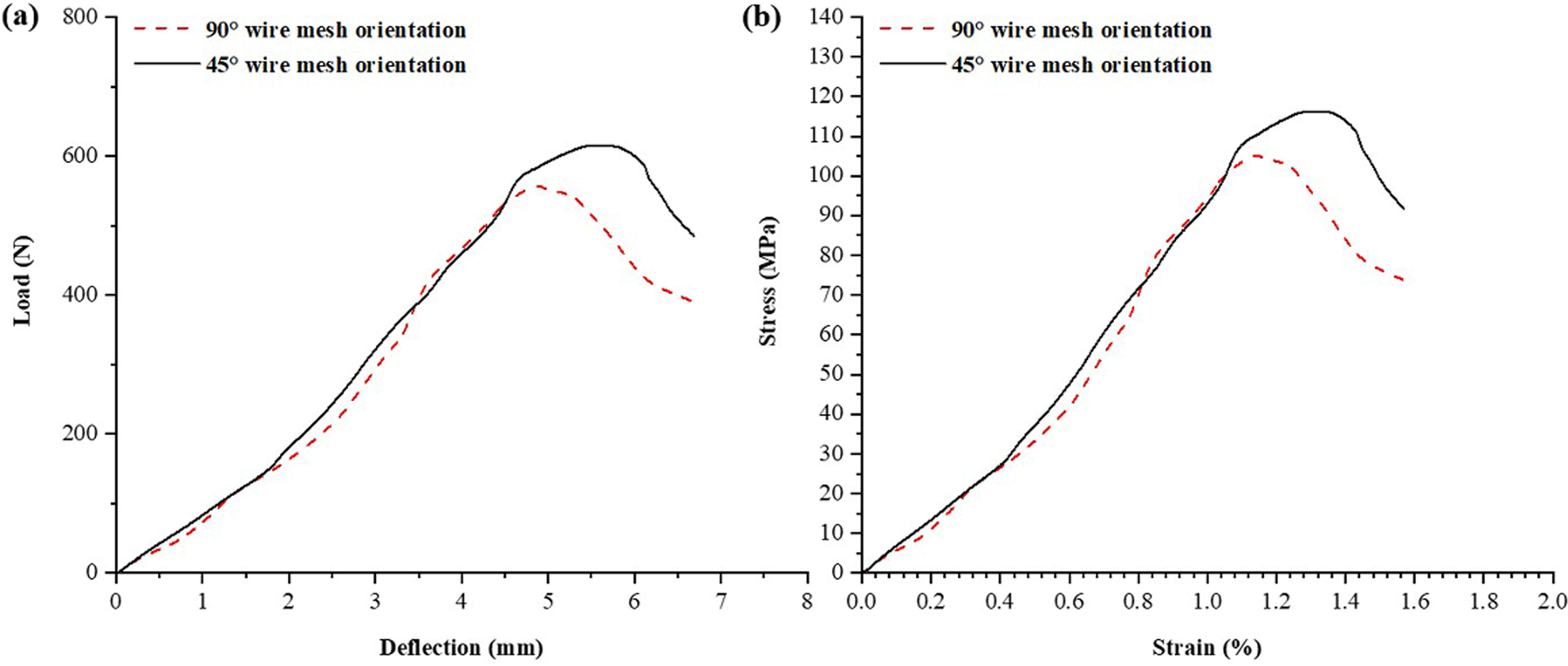
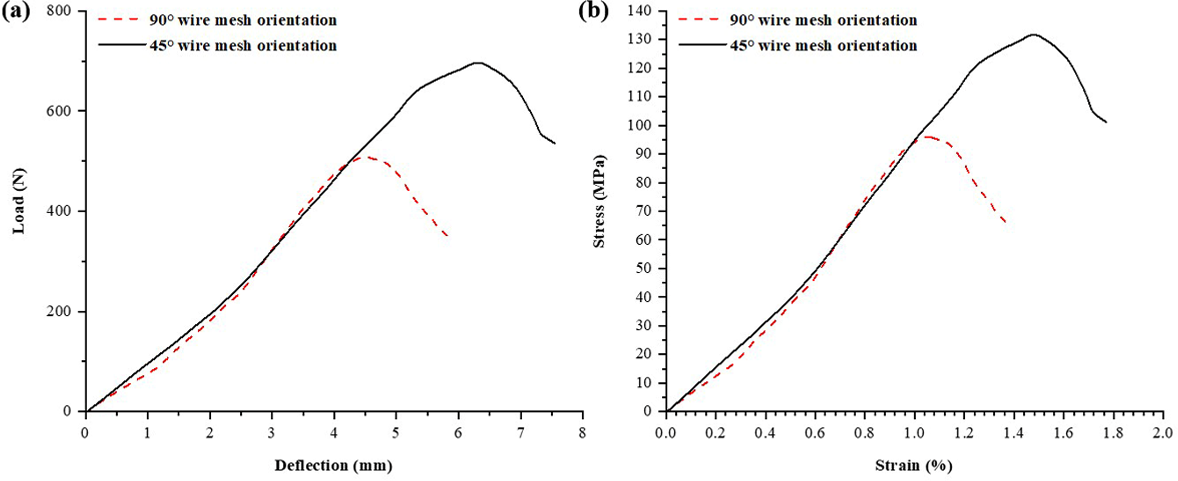
Figures 17 and 18 depict the load versus elongation at break curves and stress versus strain curves for hybrid composites reinforced with wire mesh at orientations of 45° and 90°. In the 45° oriented wire mesh reinforced hybrid composite (2′), an average maximum elongation and maximum strain of 2.24 mm and 1.35% were observed at an average applied load of 13.19 kN. Conversely, the 90° oriented wire mesh reinforced composite (1″) exhibited an average minimum elongation and minimum strain of 1.33 mm and 0.80% at an average applied load of 12.74 kN. Furthermore, the average maximum tensile strength and YS were found to be 74.83 MPa and 69.24 MPa, respectively, for the 45° oriented wire mesh reinforced hybrid composite (5′). On the other hand, the average minimum tensile strength and YS were determined to be 63.52 MPa and 58.17 MPa, respectively, for the 90° oriented wire mesh reinforced hybrid composite (4″). Based on the tensile test results, it is evident that the hybrid composite reinforced with wire mesh oriented at 45° exhibits higher tensile strength and elongation compared to the hybrid composite reinforced with wire mesh oriented at 90°.
Tensile strength of 2′ and 1″ specimen: (a) load vs elongation diagram; (b) stress vs strain diagram.
Tensile strength of 5′ and 4″ specimen: (a) load vs elongation diagram; (b) stress vs strain diagram.
Flexural properties
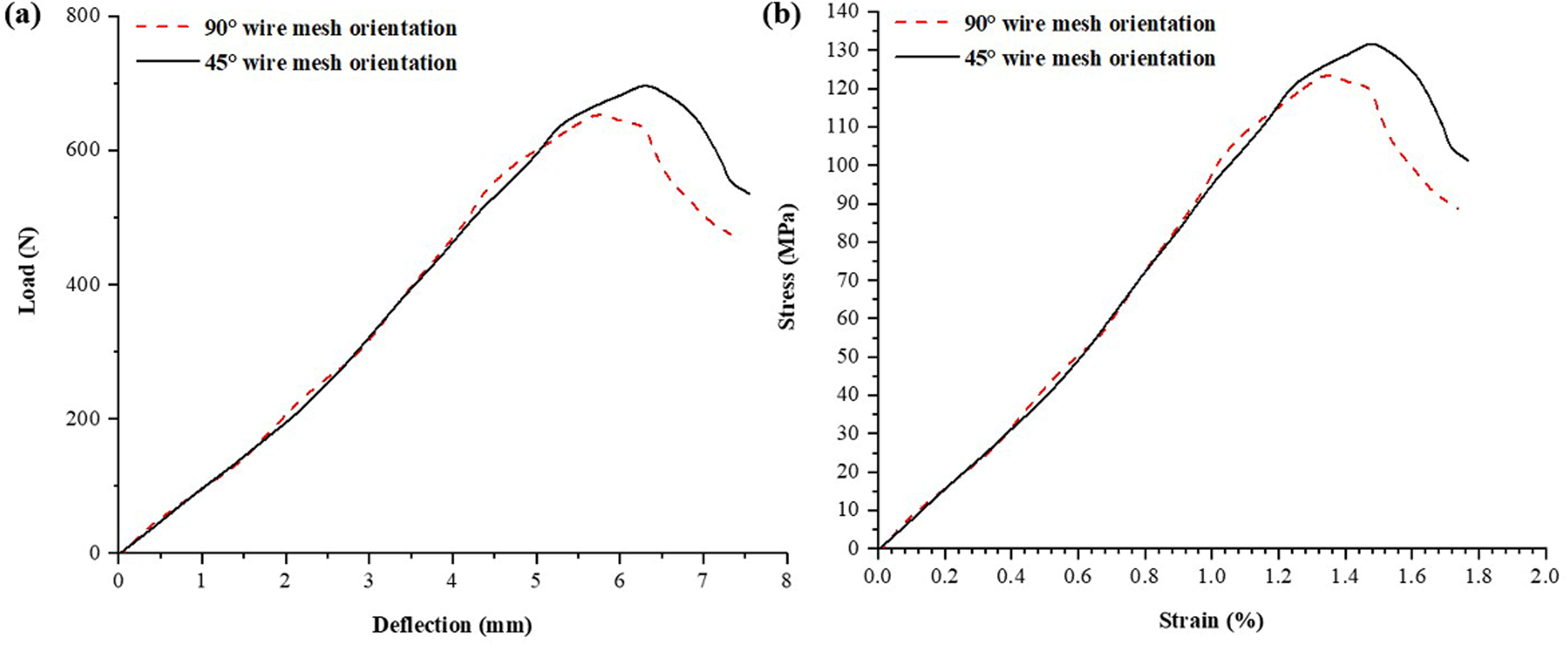
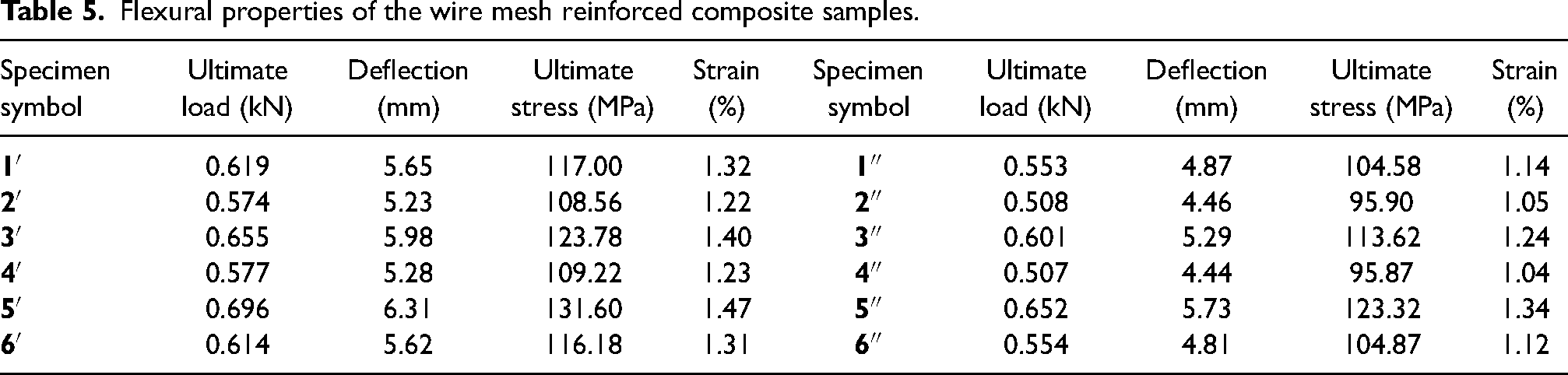
Table 5 presents the flexural characteristics of wire mesh reinforced hybrid composites with different orientations (45° and 90°). It is observed that the hybrid composites with a 45° wire mesh orientation exhibit higher flexural strength compared to those with a 90° orientation. Figures 19 to 24 illustrate the flexural behavior of the two distinct wire mesh reinforced hybrid composites. The results indicate that among the six different stacking sequences of the composites, the 45° oriented wire mesh reinforced hybrid composite (5′) shows the maximum deflection of 6.31 mm at a load of 0.696 kN, while the composite (4″) exhibits the lowest deflection of 4.44 mm at a load of 0.507 kN for flexural strength. The strong bonding and compatibility between the wire mesh and epoxy resin contribute to the maximum achieved extension. The hybrid composite reinforced with wire mesh having the stacking sequence PWJL/LJWP (specimen symbol 5′) exhibits the highest flexural strength of 131.60 MPa, whereas the stacking sequence JPWL/LWPJ (specimen symbol 4″) exhibits the lowest flexural strength of 95.87 MPa, as shown in Figure 25. The presence of wire mesh close to the centre, along with good adhesion and hybridization between jute and palmyra fibers, leads to a reduction in circumferential stress and an increase in flexural strength.
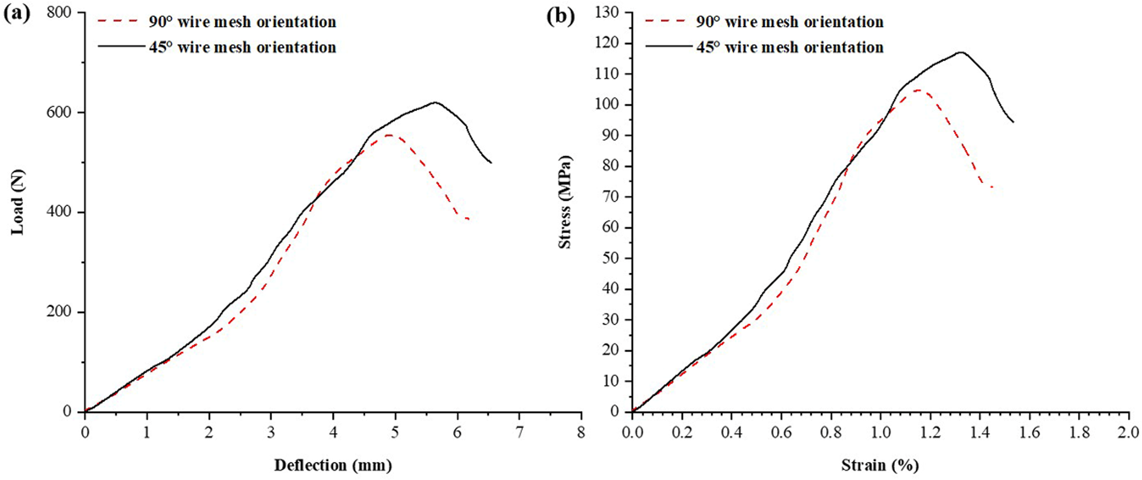
Flexural strength of group sample-1: (a) flexural load vs deflection diagram; (b) flexural stress vs strain diagram.
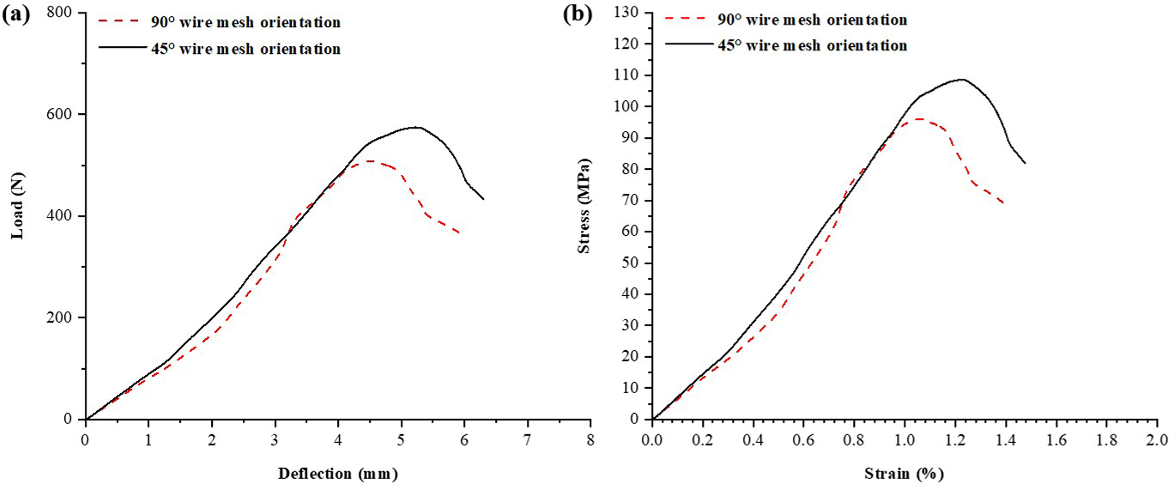
Flexural strength of group sample-2: (a) flexural load vs deflection diagram; (b) flexural stress vs strain diagram.
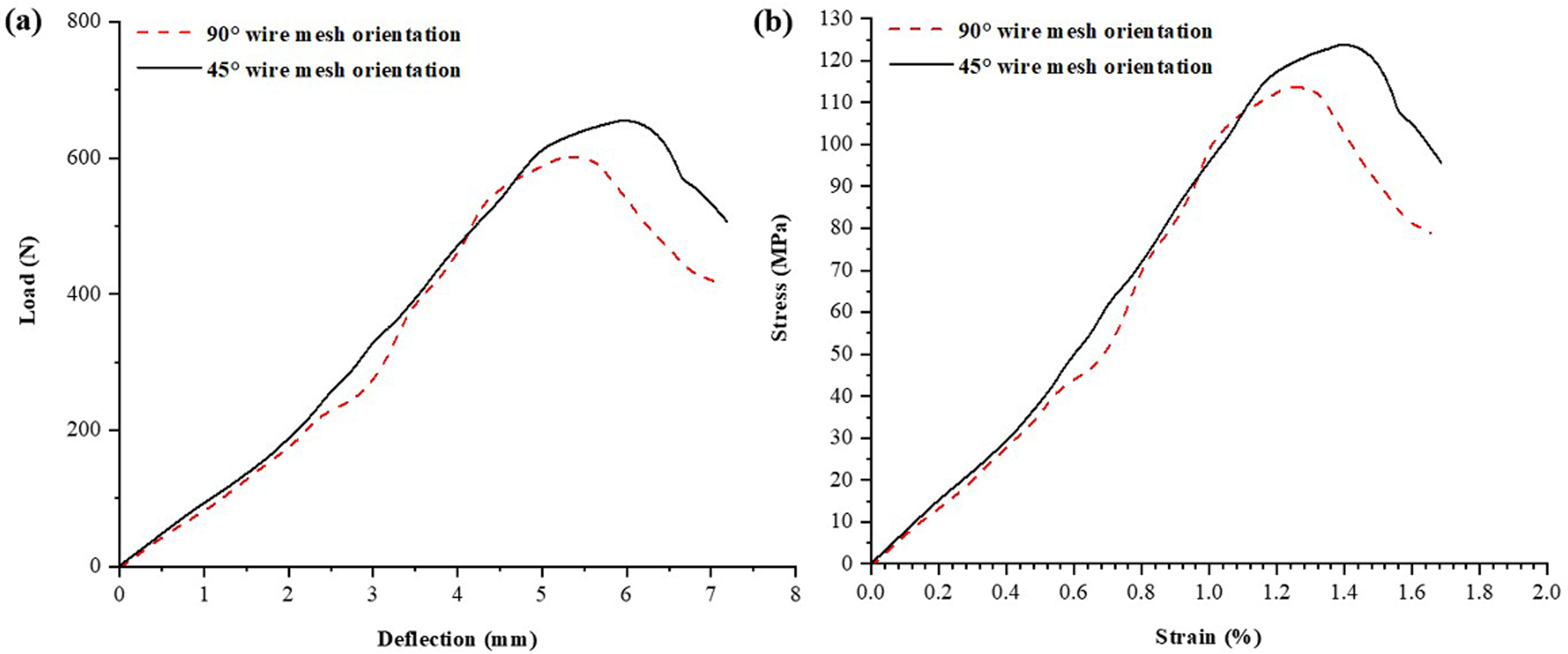
Flexural strength of group sample-3: (a) flexural load vs deflection diagram; (b) flexural stress vs strain diagram.
Flexural strength of group sample-4: (a) flexural load vs deflection diagram; (b) flexural stress vs strain diagram.
Flexural strength of group sample-5: (a) flexural load vs deflection diagram; (b) flexural stress vs strain diagram.
Flexural strength of group sample-6: (a) flexural load vs deflection diagram; (b) flexural stress vs strain diagram.
Flexural strength of 5′ and 4″ sample: (a) flexural load vs deflection diagram; (b) flexural stress vs strain diagram.
Flexural properties of the wire mesh reinforced composite samples.
Impact properties
The impact strength of the fabricated hybrid composites with wire mesh reinforcement, consisting of two different wire mesh orientations (45° and 90°) and six various stacking sequences of fibers, was determined through the Charpy impact test. The Charpy test results provide information about the composite samples’ energy absorption capability. The highest average value obtained from the impact testing was 38.4 ± 2.2 kJ/m2, while the lowest average value of 21.76 ± 2.2 kJ/m2 was observed in sample 1″. The sample 5′ exhibited the highest impact strength among the tested samples.
As depicted in Figure 26, the impact strength values for specimens 2′, 4′, and 6′ are nearly identical regardless of the stacking order and wire mesh orientation. However, the composite specimens in group A, known for their brittleness, display a lower average impact strength compared to the samples in the other specimen group.
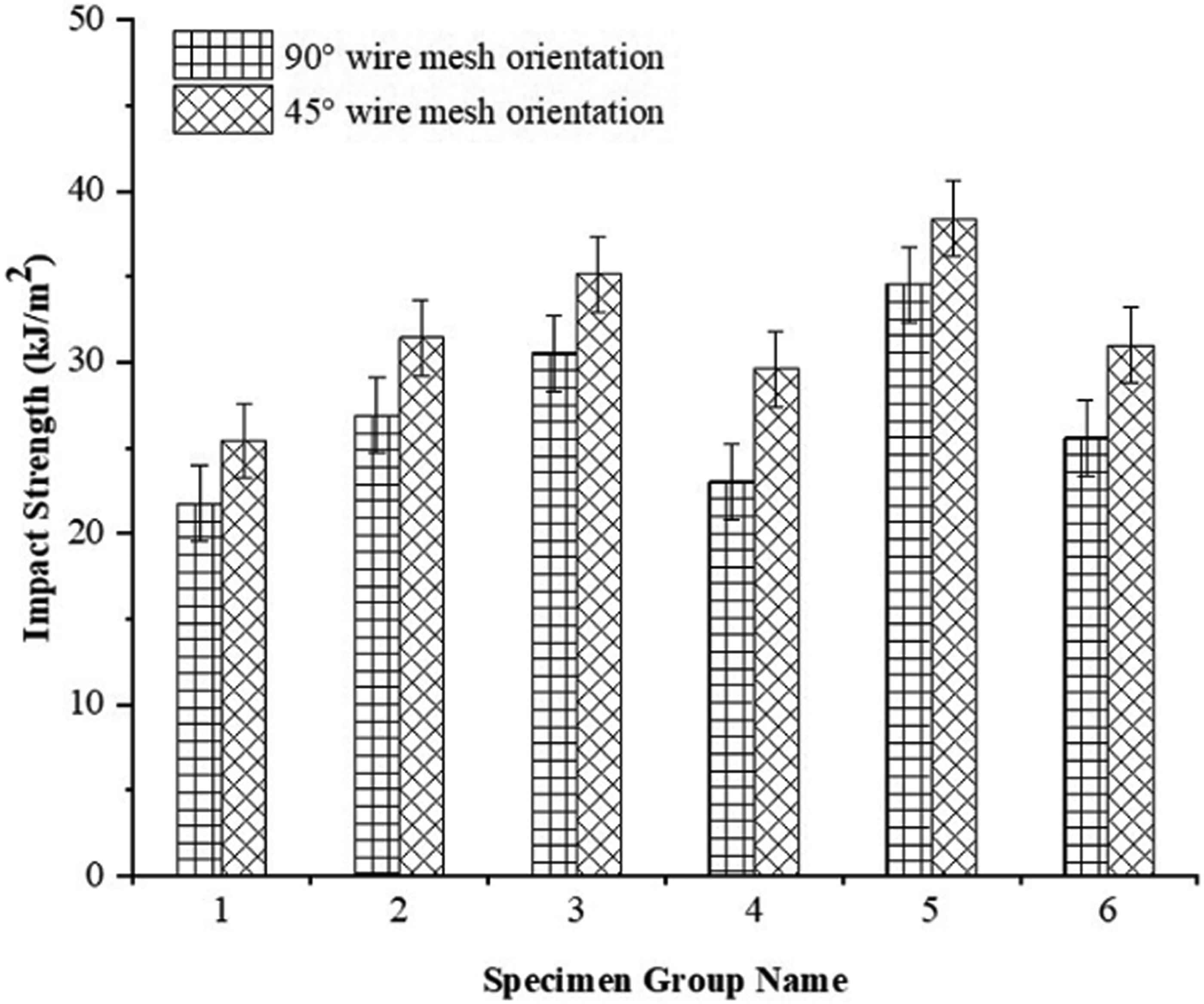
Impact strength of wire mesh reinforced hybrid composites.
For each sample group, the average impact strength value obtained from the 45° wire mesh reinforced composite orientation is higher than that of the 90° wire mesh reinforced composites.
Among the specimen groups, particularly the 5′ specimen symbol exhibits the maximum impact strength. This is because the 45° wire mesh reinforcement provides stronger resistance against fiber fracture and debonding compared to the 90° oriented wire mesh. Efficient energy dissipation occurs through fiber pull-out from the matrix composites. Various variables such as weight/volume ratio, geometry, fiber properties, and fiber orientation influence the impact strength performance of the composite sample.51,52 Interlaminar and interfacial adhesion are crucial factors that significantly impact the impact characteristics. The overall weight content of the composite sample also affects the impact strength result. 53 Inadequate fiber-to-matrix adhesion leads to the presence of voids, which in turn hinders the performance of the hybrid composite. The presence of voids reduces the resin-rich area, thereby limiting the composite's ability to absorb energy.
Hardness properties
In accordance with the ASTM E10-18 standard, the prepared samples are placed on the anvil of the BHN hardness tester. The hardness property of the fabricated wire mesh reinforced hybrid composites is investigated by applying an indentation load normal to the fiber length on both the top and bottom sides of the samples. Generally, the presence of fibers increases the moduli of the composite, resulting in improved hardness. This is because the relative fiber volume and modulus are related to hardness. Considering that the effects of fiber loading and post-curing time are nearly the same for all wire mesh reinforced hybrid composites, an average hardness value of 955 BHN was obtained regardless of the stacking sequence of the fibers. Although the six different stacking sequences of the composites had approximately the same indentation depth.
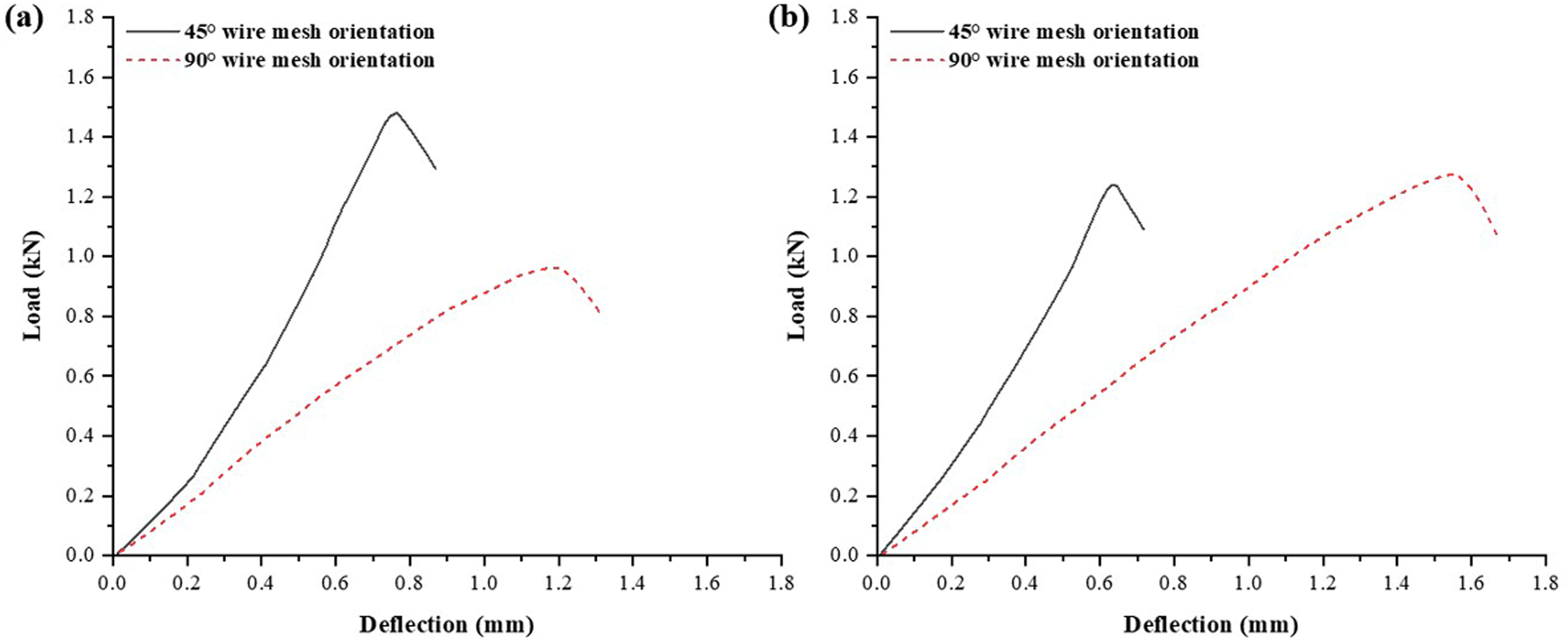
Interlaminar shear strength behavior
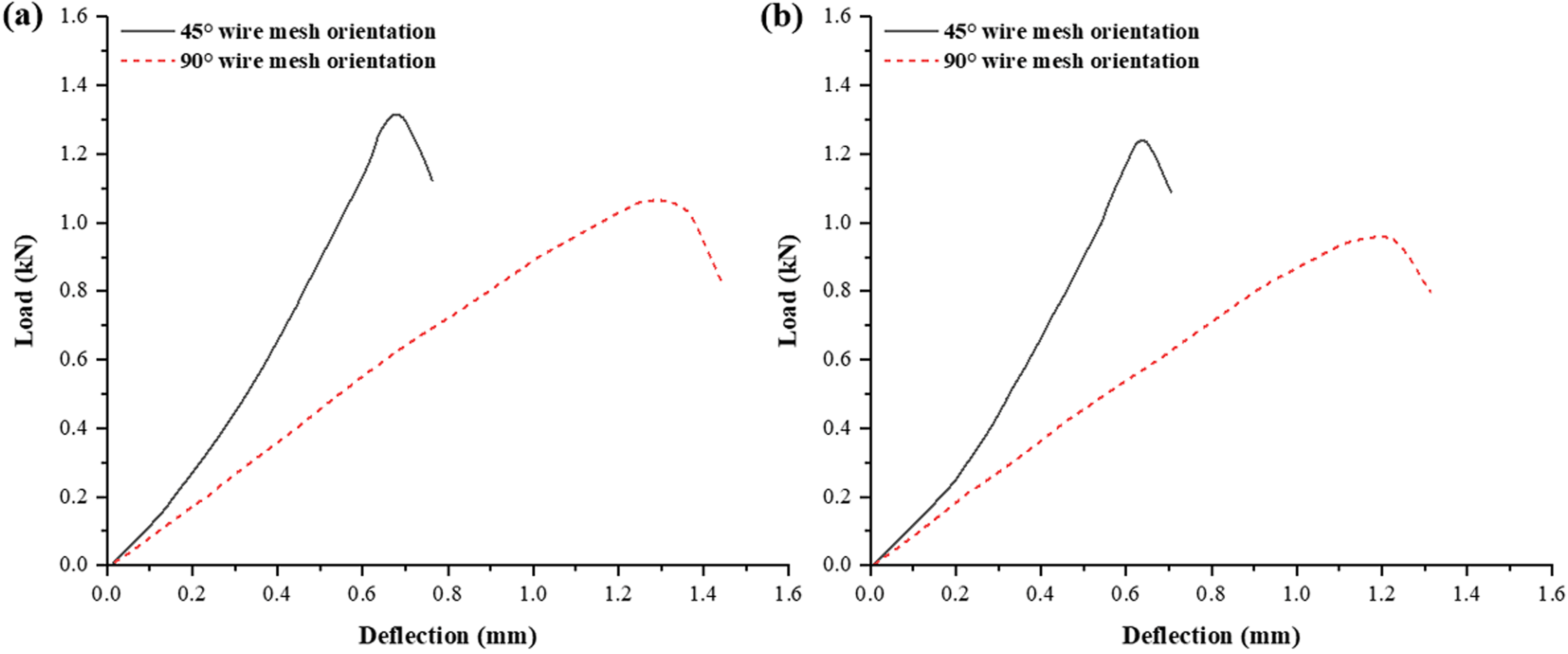
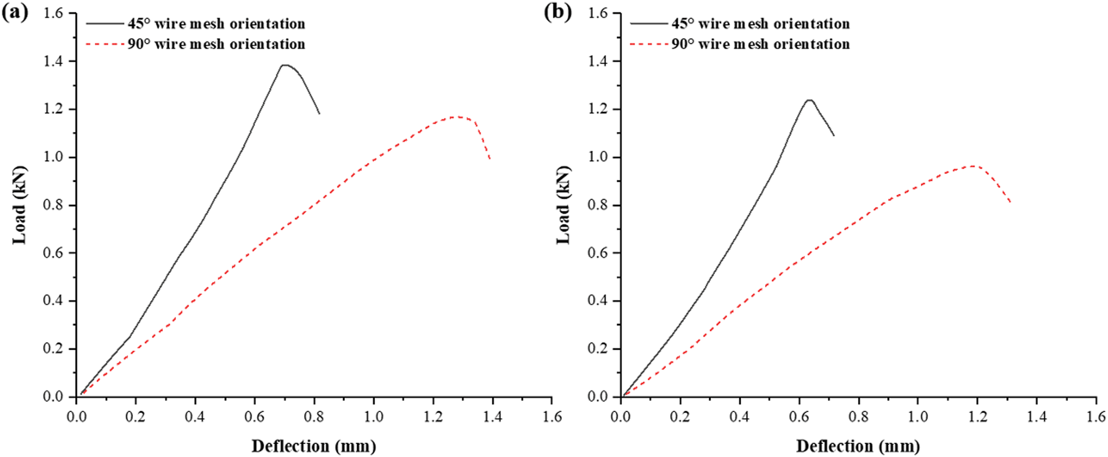
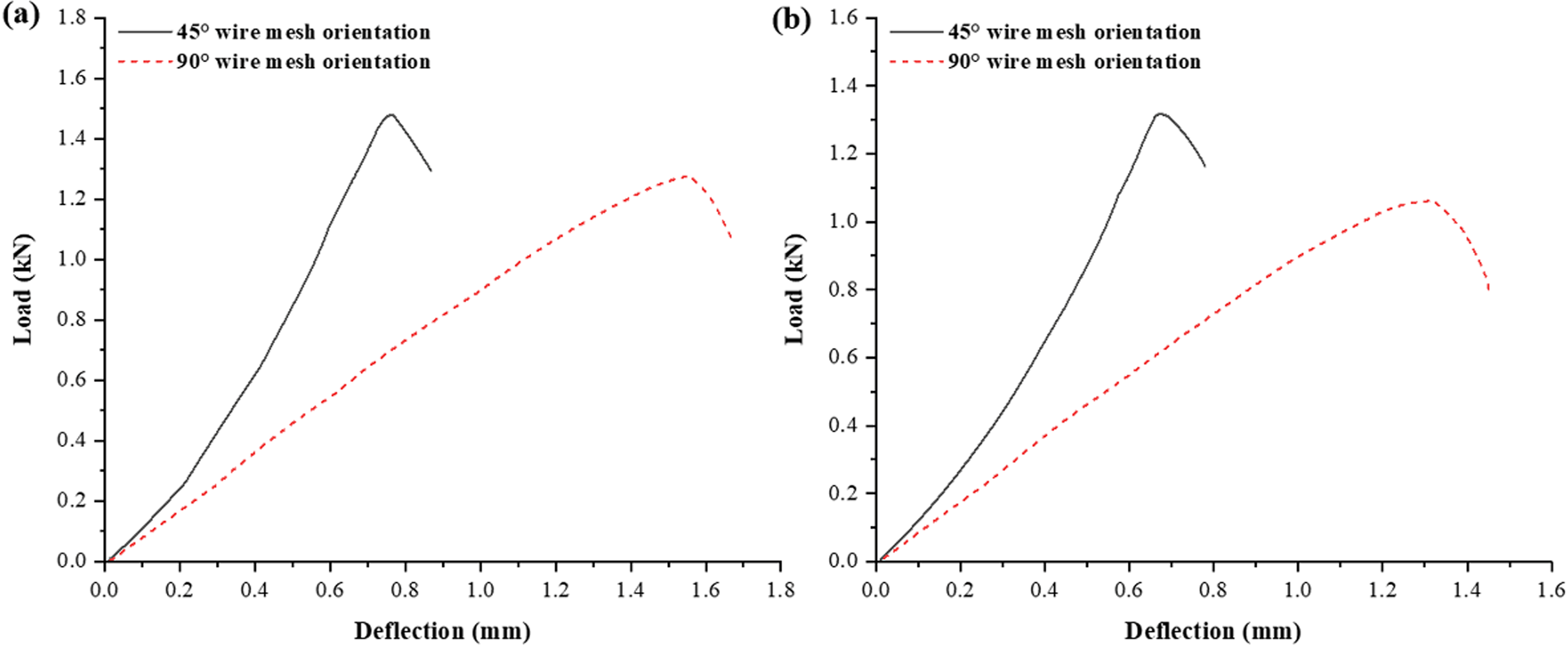
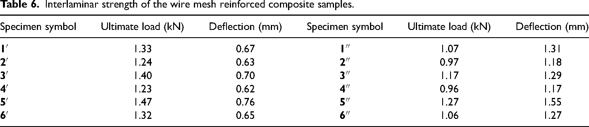
The ILSS test is conducted to evaluate the bonding quality between fibers, wire mesh, and resin. The strength of the interface or interphase is determined by the adhesion of the epoxy resin to the wire mesh and other fibers. The presence of wire mesh reinforcement significantly enhances the delamination toughness of the composite. When comparing the hybrid composites with 45° and 90° wire mesh reinforcement, the 45° orientation composite (5′) demonstrates superior delamination toughness. Figures 27 to 29 illustrate typical load-displacement diagrams for wire mesh reinforced hybrid composites with both 45° and 90° orientations. Table 6 presents the ILSS characteristics of the fabricated hybrid composites with differently oriented (45° and 90°) wire mesh reinforcement.
ILSS behavior (load vs deflection diagram): (a) group sample-1; (b) group sample-2.
ILSS behavior (load vs deflection diagram): (a) group sample-3; (b) group sample-4.
ILSS behavior (load vs deflection diagram): (a) group sample-5 (b) group sample-6.
Interlaminar strength of the wire mesh reinforced composite samples.
In each sample group, both orientations (45° and 90°) of wire mesh-reinforced composites exhibit an initial loading stage that is approximately linear. However, the 90°-oriented wire mesh composites demonstrate a greater tendency to lean, resulting in higher deflection for the same applied force compared to the 45° wire mesh-oriented composites. This lean tendency indicates a greater deflection of the composite. The linear relationship between load and deflection continues until the curve reaches an apparent elastic limit, after which it transitions to a declining trend. Following the peak load, the 90° wire mesh-oriented composites (4″ and 2″) exhibit a significant decrease in load. The highest peak load of 1.47 kN was achieved by the 5′ composite, while the lowest peak load of 0.96 kN was observed in the 4″ composite. Additionally, the maximum deflection of 1.55 mm was recorded in the 5″ composite, while the minimum deflection of 0.62 mm was observed in the 4′ composite, as depicted in Figure 30.
Maximum and minimum ILSS behavior of group sample-5 and 4: (a) sample-5′ and 4″; (b) sample-5″ and 4′.
Furthermore, Figure 31 illustrates the interlaminar behavior of laminated natural fibers (jute, luffa, and palmyra) and wire mesh-reinforced epoxy-based hybrid composites through microstructural images. The hybrid composite (5′) with a 45° wire mesh orientation exhibits enhanced bonding between the layers of natural fibers and SS303 steel wire mesh, as evident from the picture. Delamination is effectively resisted, as observed. Under high tensile stress, some transverse tensile cracks appear in the bottom layer of the laminate. On the other hand, in the hybrid composite (4″) with a 90° wire mesh orientation, separation between the natural fibers and SS303 steel wire mesh is visible. Additionally, a few tensile cracks have been observed in the lowest layer.
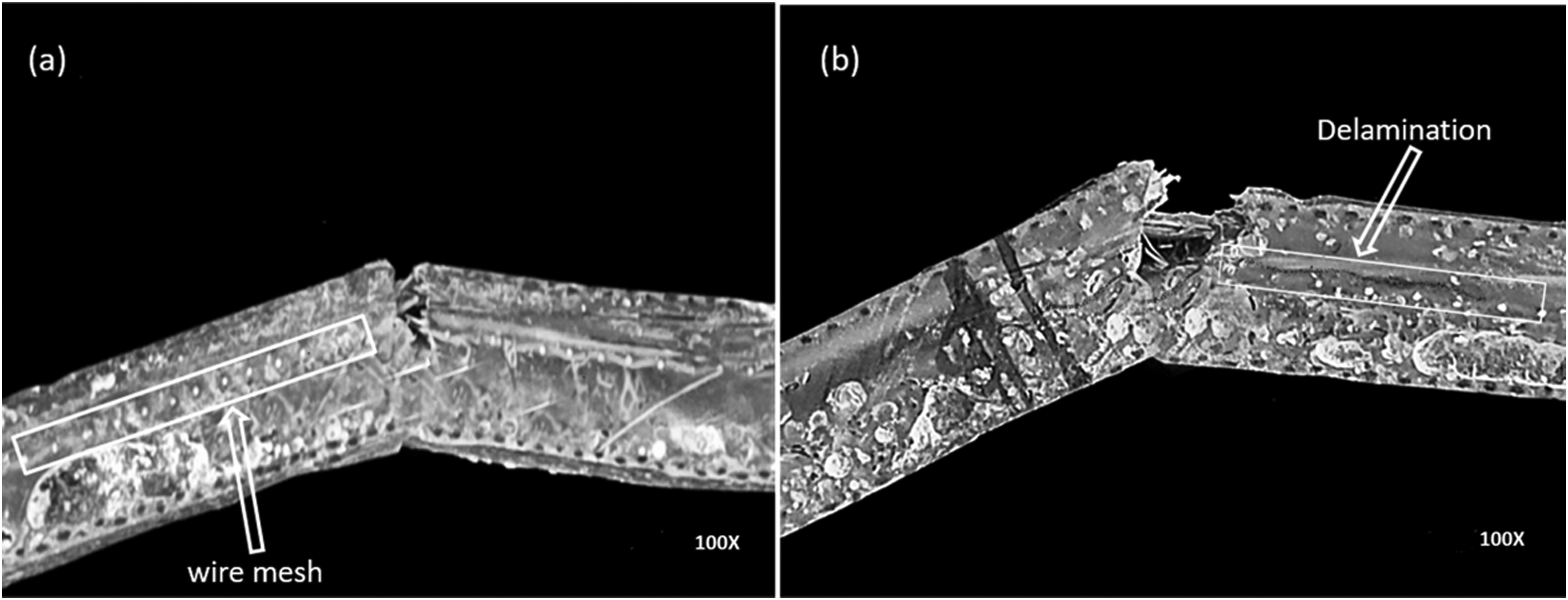
Interfacial bonding between fibers and wire mesh reinforcement in the hybrid samples: (a) 45° wire mesh orientation and (b) 90° wire mesh orientation.
Dynamic mechanical analysis behavior
The dynamic mechanical properties of wire mesh-reinforced hybrid composites from group “E” with two distinct wire mesh orientations (45° and 90°) were evaluated using Perkin Elmer’s DMA-8000. The assessment focused on analyzing the glassy, transitional, and rubbery zones of the composites. Among the six laminated configurations, sample “5” (PWJL/LJWP) exhibited the most promising results. The storage modulus (E′), loss modulus (E″), and damping factors (tan δ) were measured as a function of time and frequency. The evaluation included three test specimens operating at different frequencies (0.5, 1.0, and 5.0 Hz) for both wire mesh orientations. The obtained results, presented in Figures 32 to 38, highlight significant changes observed at the transition region compared to the glassy and rubbery regions.
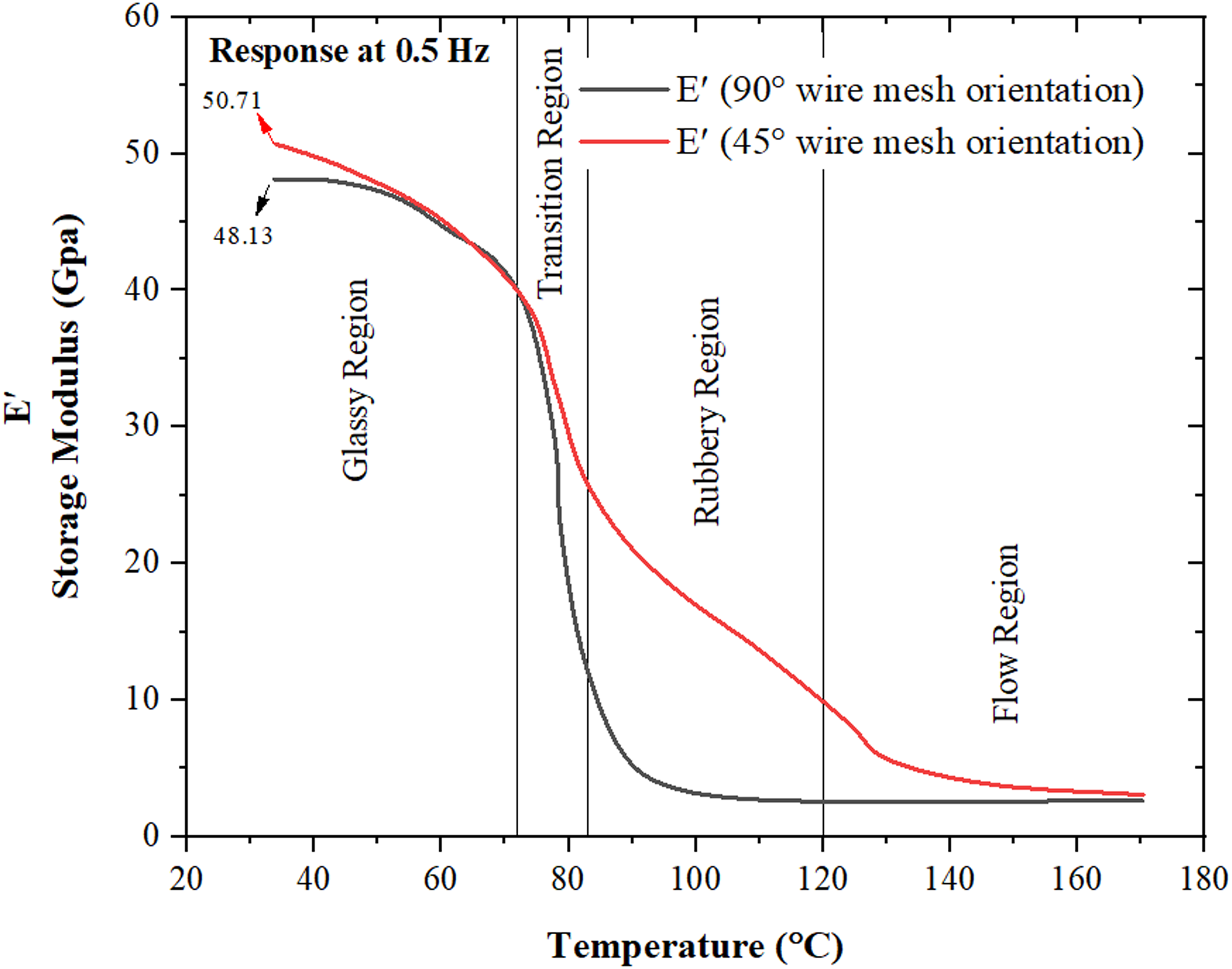
Behavior of storage modulus of 45° and 90° wire mesh oriented reinforced hybrid at 0.5 Hz frequency.
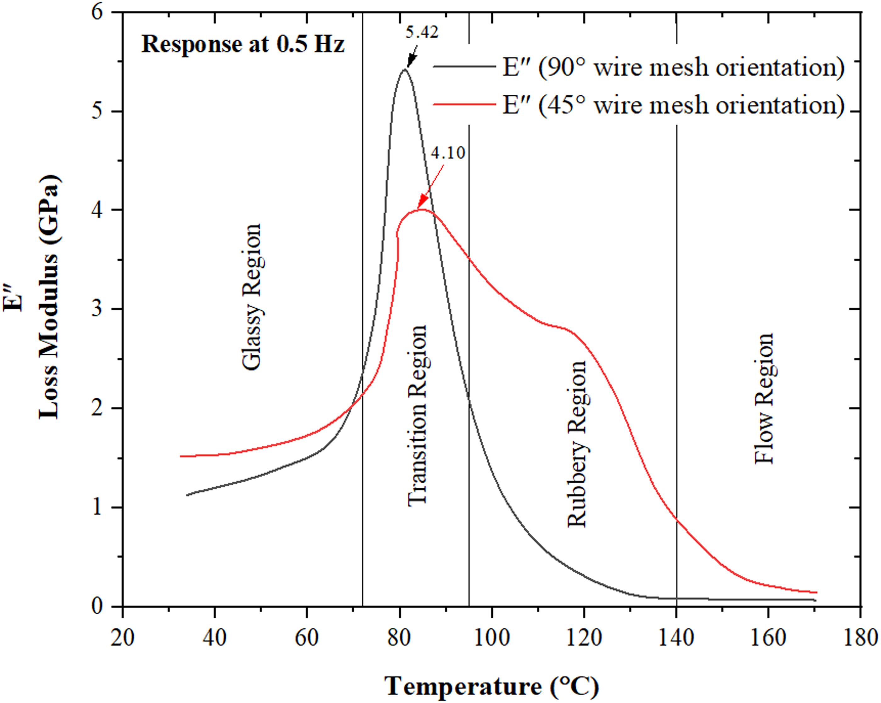
Behavior of loss modulus of 45° and 90° wire mesh oriented reinforced hybrid at 0.5 Hz frequency.
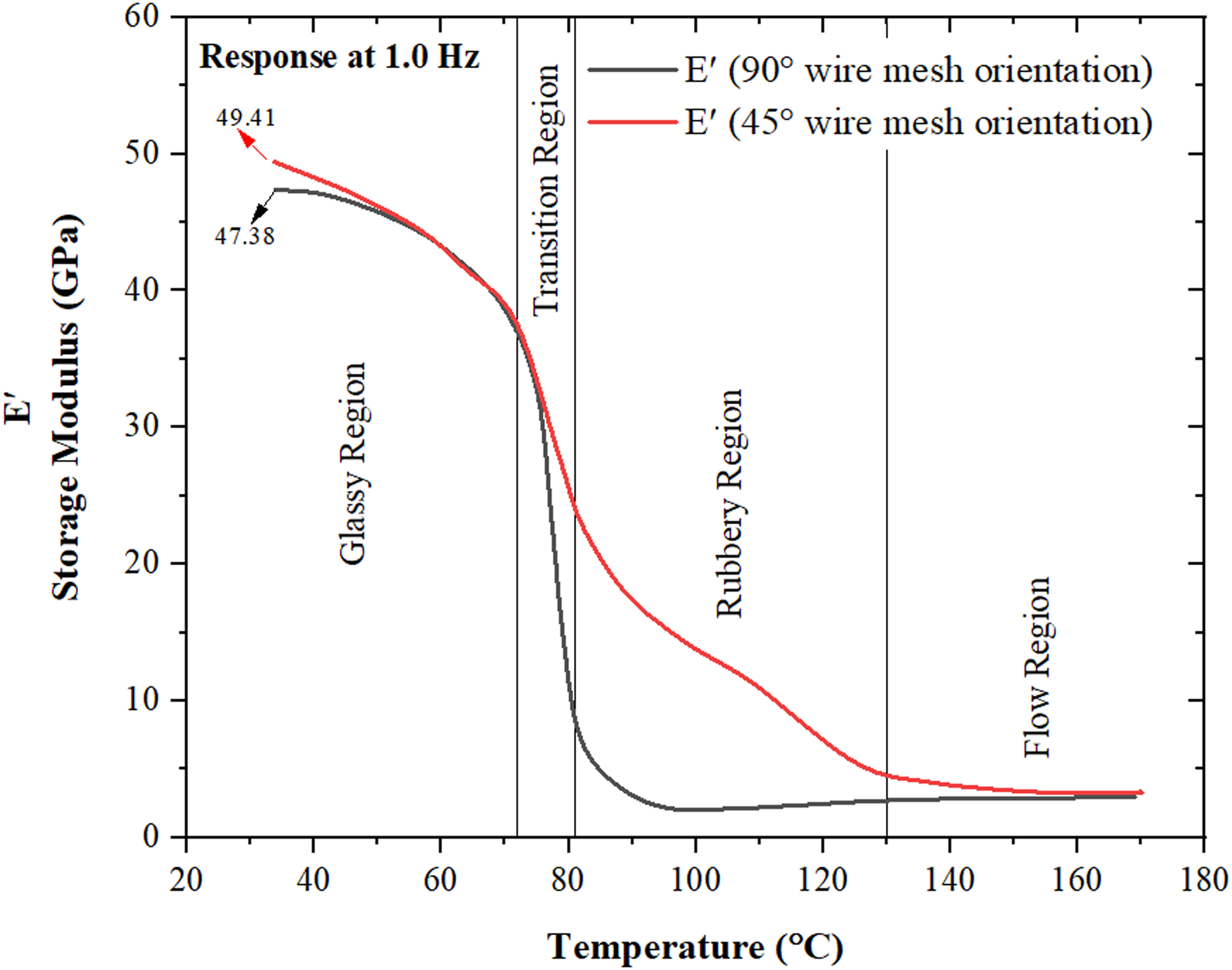
Behavior of storage modulus of 45° and 90° wire mesh oriented reinforced hybrid at 1.0 Hz frequency.
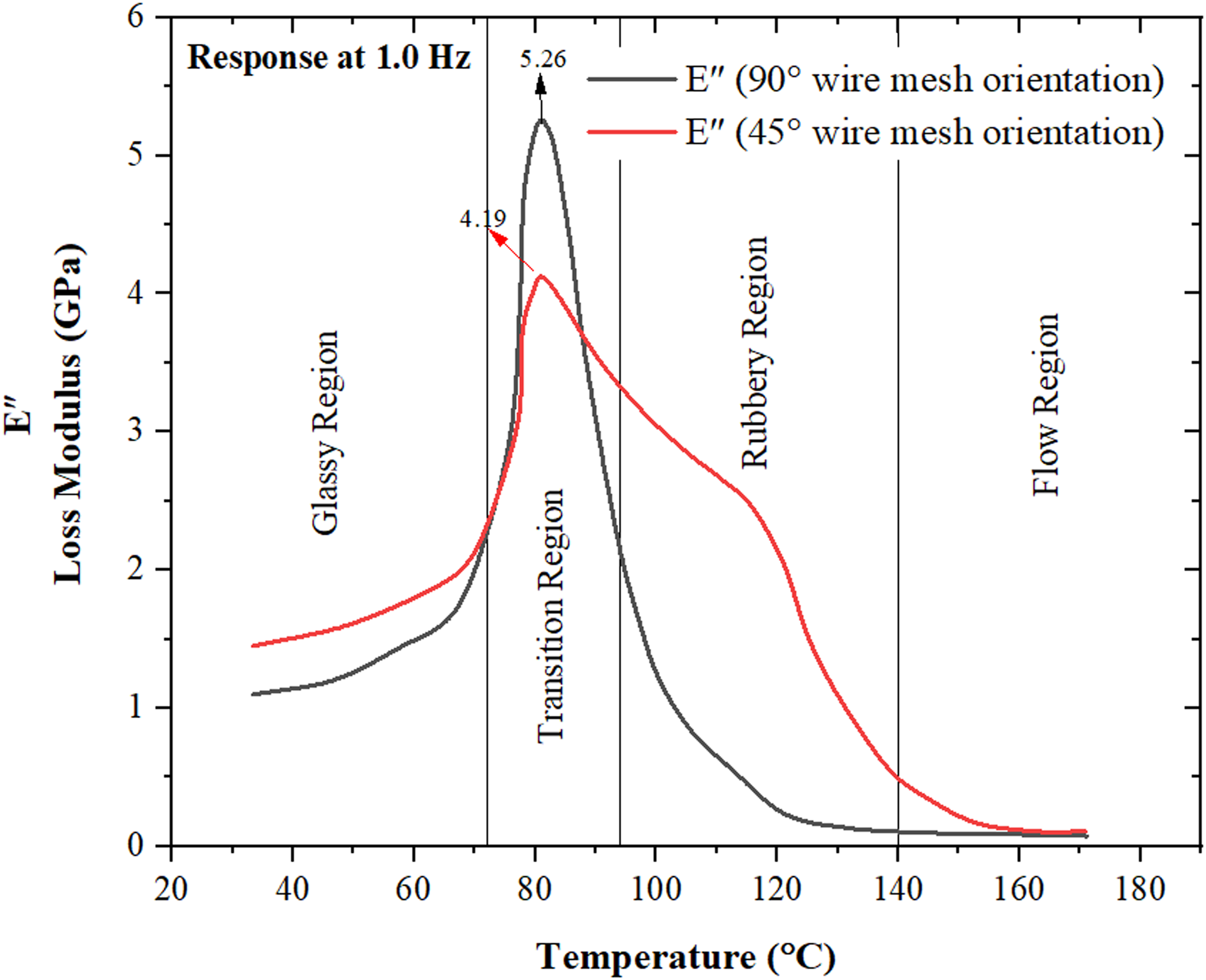
Behavior of loss modulus of 45° and 90° wire mesh oriented reinforced hybrid at 1.0 Hz frequency.
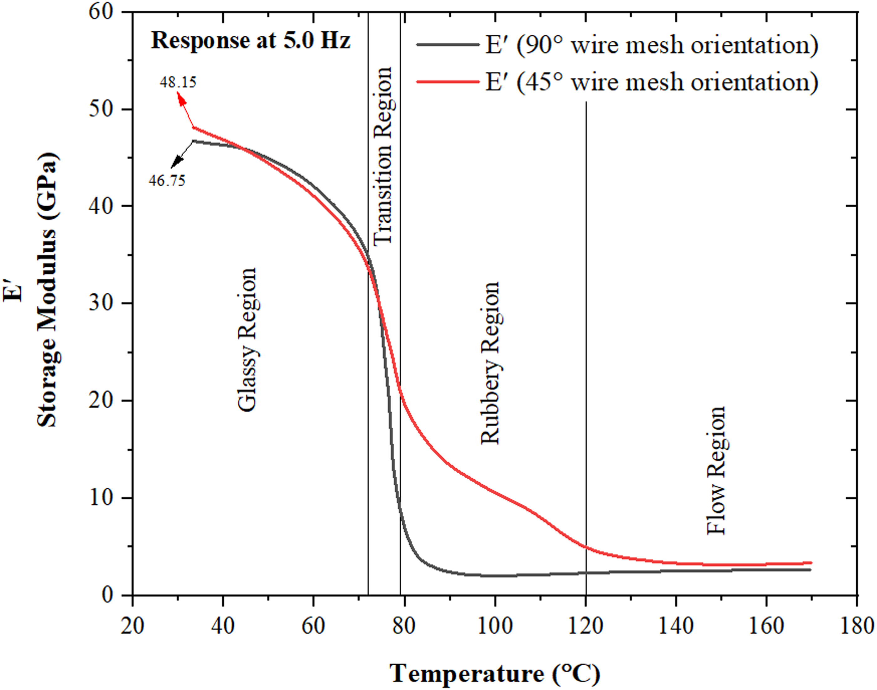
Behavior of storage modulus of 45° and 90° wire mesh oriented reinforced hybrid at 5.0Hz frequency.
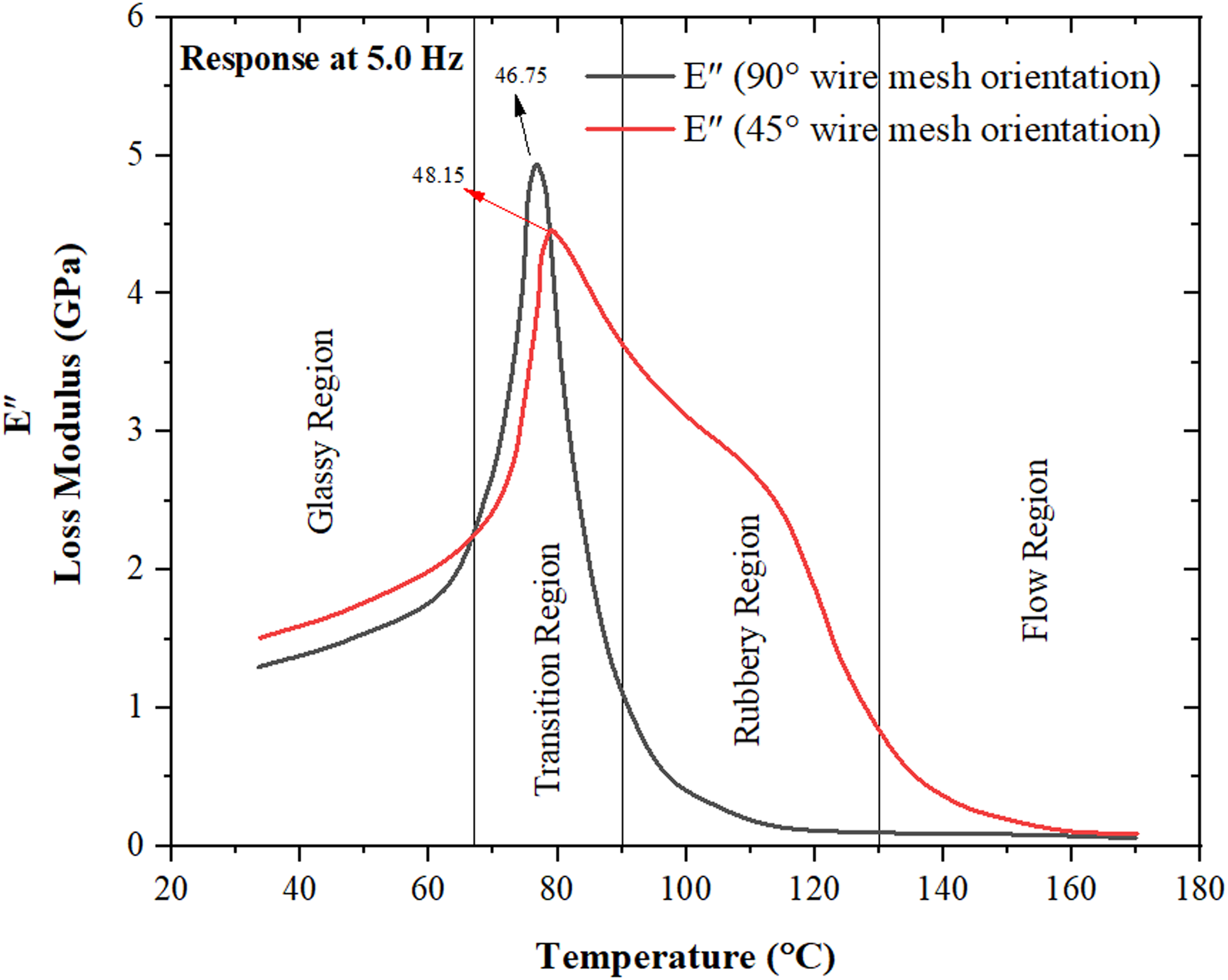
Behavior of loss modulus of 45° and 90° wire mesh oriented reinforced hybrid at 5.0 Hz frequency.
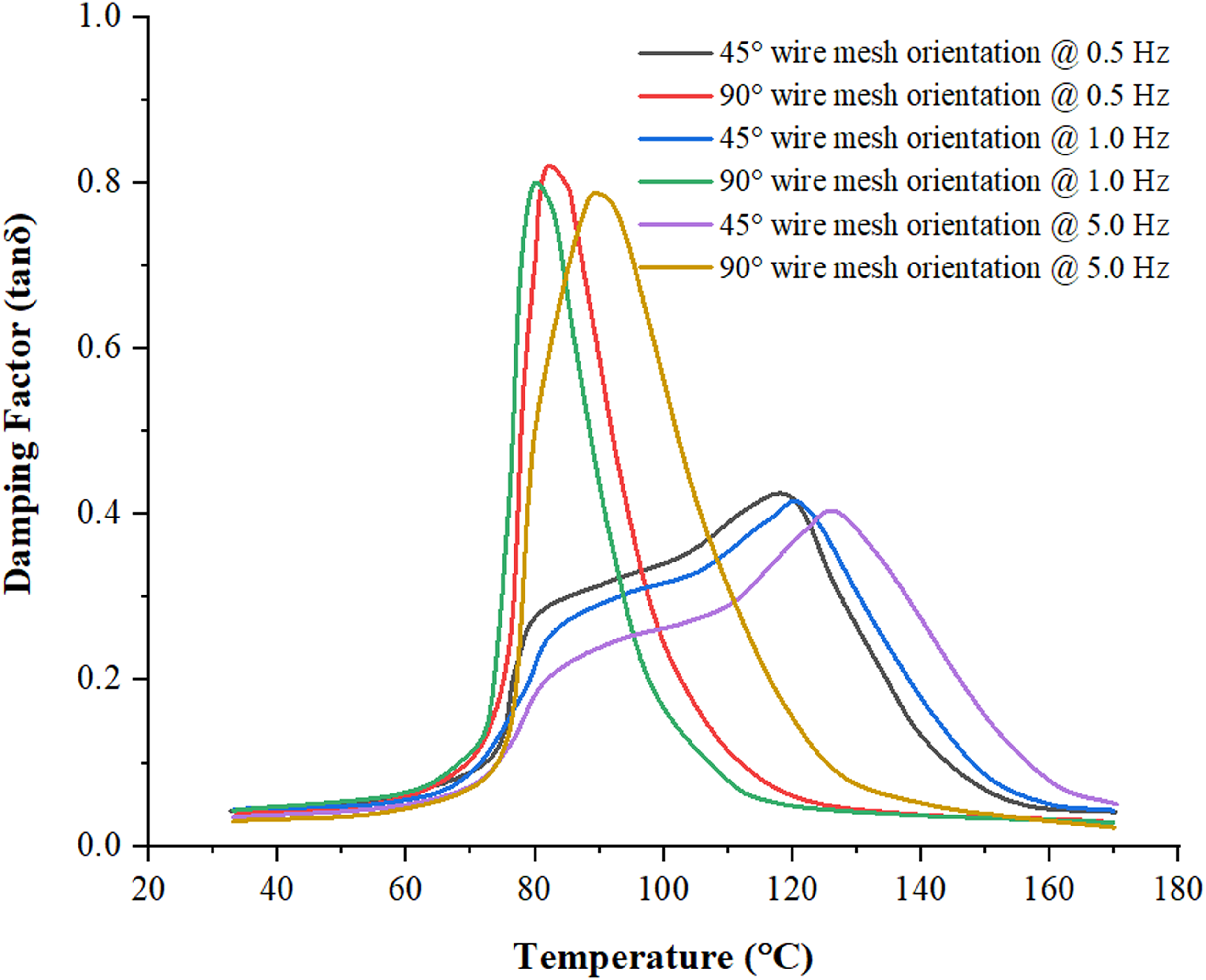
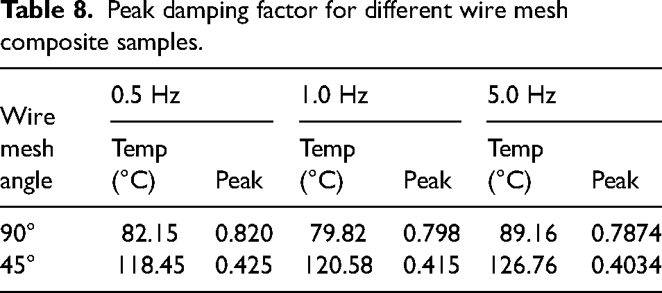
Damping factor of the wire mesh (45° and 90°) composite samples at different frequencies.
A higher storage modulus of 50.71 GPa at 0.5 Hz was observed for the 45° wire mesh composite in the glassy state, as depicted in Figure 32. However, with the addition of heat at a rate of 4°C/min, the storage modulus starts to decrease. This rapid drop in storage modulus at the transition zone is attributed to increased molecular dislocation. 54 Figures 32, 34, and 36 clearly illustrate that the 45° wire mesh composite consistently exhibits a higher storage modulus than the 90° wire mesh composite across all three regions. The glass transition temperature for the 45° orientation is lower compared to the 90° orientation, as shown in Table 7. Furthermore, there are minimal shifts in the storage modulus values for these two hybrid composites across the frequency range of 0.5, 1.0, and 5.0 Hz, as indicated in Table 7.
Amplitude of storage and loss modulus at different frequency.
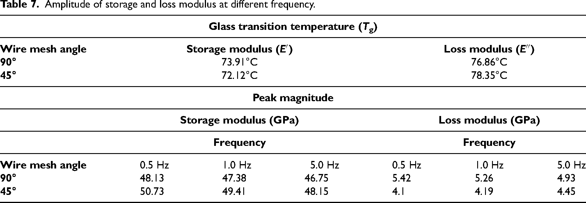
In the glassy zone, the 45° wire mesh composite exhibits a loss modulus of 1.5 GPa at a frequency of 0.5 Hz, which is higher than the loss modulus of the 90° wire mesh composite. However, in the transition zone, the 90° wire mesh composite demonstrates a higher loss modulus (E″) as shown in Table 7. This effect can be attributed to the sharp decrease in storage modulus values observed in the transition region (Figures 33, 35, and 37). The presence of reinforcement between the fibers, matrix, and wire mesh contributes to a broad curve in the transition and rubber regions for the 45° oriented wire mesh composite (Figures 32 to 37). Moreover, compared to other wire mesh composite orientations, the 45° wire mesh composite exhibits larger loss modulus values in the rubber region. 55
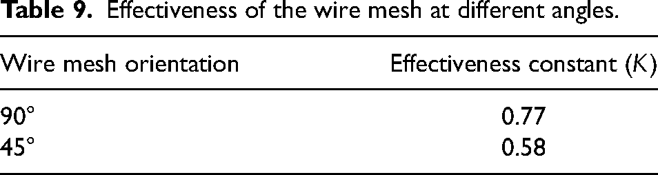
By utilizing the storage modulus (E′) and the loss modulus (E″), the damping factor (tan δ) was calculated, revealing the behavioral trend of the wire mesh composite as depicted in Figure 38. While the tan values only exhibit slight differences in the glassy region, the 90° wire mesh composite demonstrates exceptionally high damping factor values throughout the frequency range (0.5, 1.0, and 5.0 Hz) in the transition region, as shown in Figure 38. The damping factor of the 90° wire mesh composite specimen appears to be influenced by the storage modulus in the transition region. In the rubbery region, the amplitude of the damping factor for the 45° wire mesh composite specimen shifts with changes in frequency, as indicated in Table 8. Due to the orientation of the wire mesh and the disparity between its storage modulus (E′) and loss modulus (E″) in the transition zone, the 45° wire mesh composite exhibits the lowest peak tan δ across the entire frequency range (0.5, 1.0, and 5.0 Hz). Furthermore, the elevated temperatures in the rubbery region result in polymer dilution, leading to a reduction in modulus value. 56
Peak damping factor for different wire mesh composite samples.
Effectiveness constant
Wire mesh increases the storage modulus of hybrid composites effectively, and this improvement can be represented by a factor of 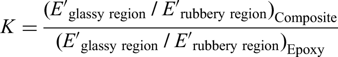
Effectiveness of the wire mesh at different angles.
Water absorption behavior
Water absorption behavior testing is utilized as a means to assess the durability of the fabricated composites. This testing helps determine the extent of water absorption exhibited by the laminated natural fiber and wire mesh reinforced epoxy composites under different water conditions, namely distilled water, normal water, and saltwater. These three water conditions are chosen to simulate real-life scenarios. Figure 39 illustrates the water absorption curves of the various composite specimens submerged for a duration of 105 days. The graph demonstrates that initially, as the immersion duration increases, the specimens absorb a relatively higher amount of water. However, this absorption rate gradually decreases over time. The water absorption behavior of the “5” group samples (PWJL/LJWP) with both 45° and 90° wire mesh orientations is examined under all three water conditions. The primary water absorption of the composites is observed around the 100-day mark after immersion, after which no significant changes are observed. It is worth noting that the initial hours and days show a rapid water absorption phase. Furthermore, the observations indicate that the hybridization of laminated natural fibers reduces the water absorption of the composites. In particular, the water absorption behavior of the “5” group samples with both 45° and 90° wire mesh orientations immersed in normal water is 40% higher compared to samples immersed in saltwater, as depicted in Figure 39. This difference can be attributed to the reduced activity of water molecules in the presence of salt, leading to the deposition of salt particles on the specimen's surface, which further hinders water absorption. 57
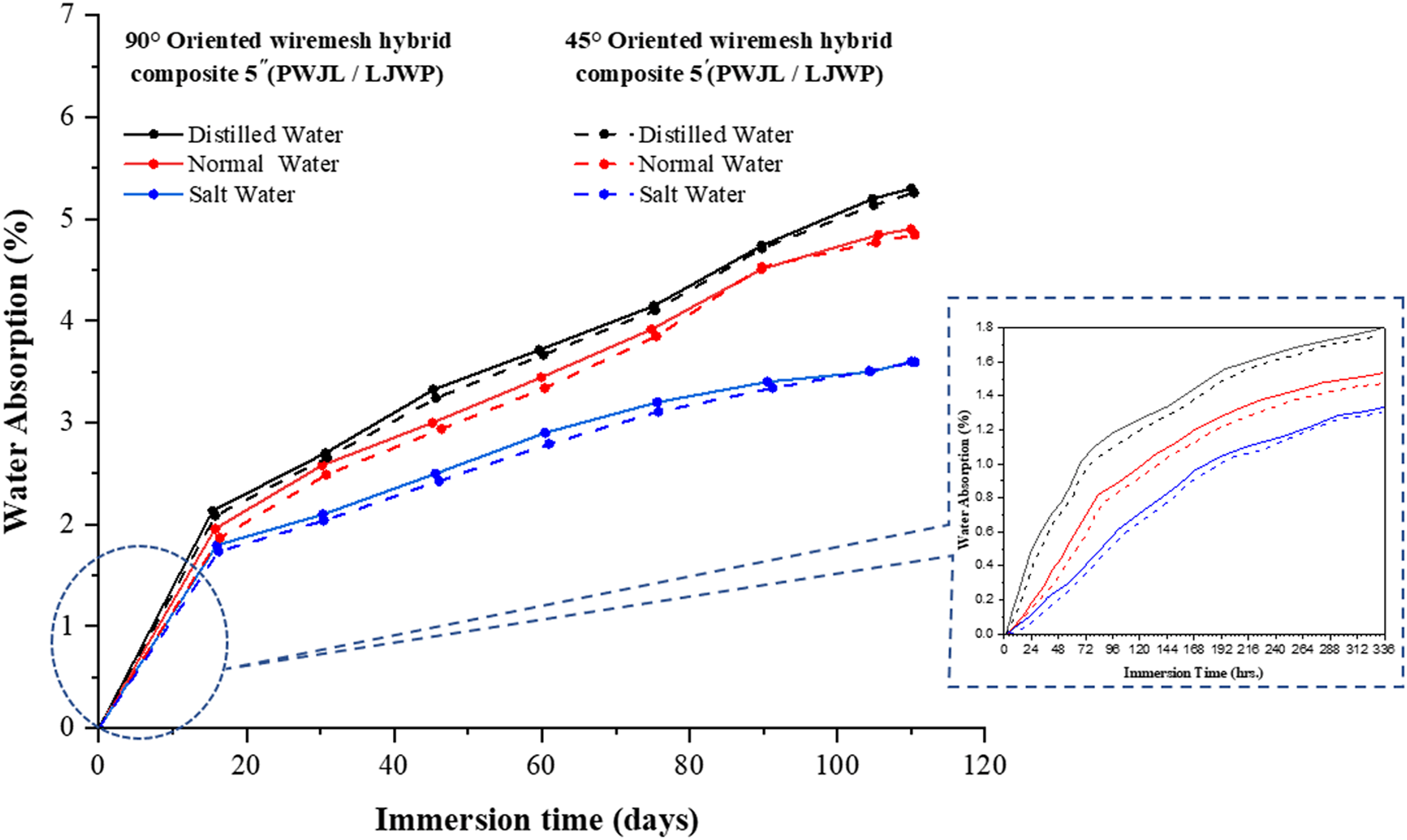
Water absorption behavior: (a) 45° wire mesh oriented and (b) 90° wire mesh oriented reinforced hybrid.
Additionally, specimens immersed in distilled water show an 8% increase in water absorption compared to normal water and a 51% increase compared to saltwater. This increased water absorption is attributed to the presence of cellulose in natural fibers, which undergoes a hydrolysis mechanism upon contact with water. Previous research has reported that cellulose hydrolysis is more pronounced in the presence of saltwater and normal water. 58 It is worth noting that no significant differences were observed between the oriented (45° and 90°) wire mesh composite samples in terms of water absorption.
Scanning Electron Microscopy analysis
During tensile and flexural tests, fiber failure can be observed in the SEM images of the steel wire mesh composite specimens, as depicted in Figure 40(a) to (e). The presence of diagonally oriented wire mesh contributes to the high anisotropy of the fabricated hybrid composite in all directions. This orientation serves as a transverse layer between the surfaces of the longitudinally adjacent fibers. The zigzag pattern of failure observed in the composite is attributed to the diagonal orientation of the wire mesh. 59
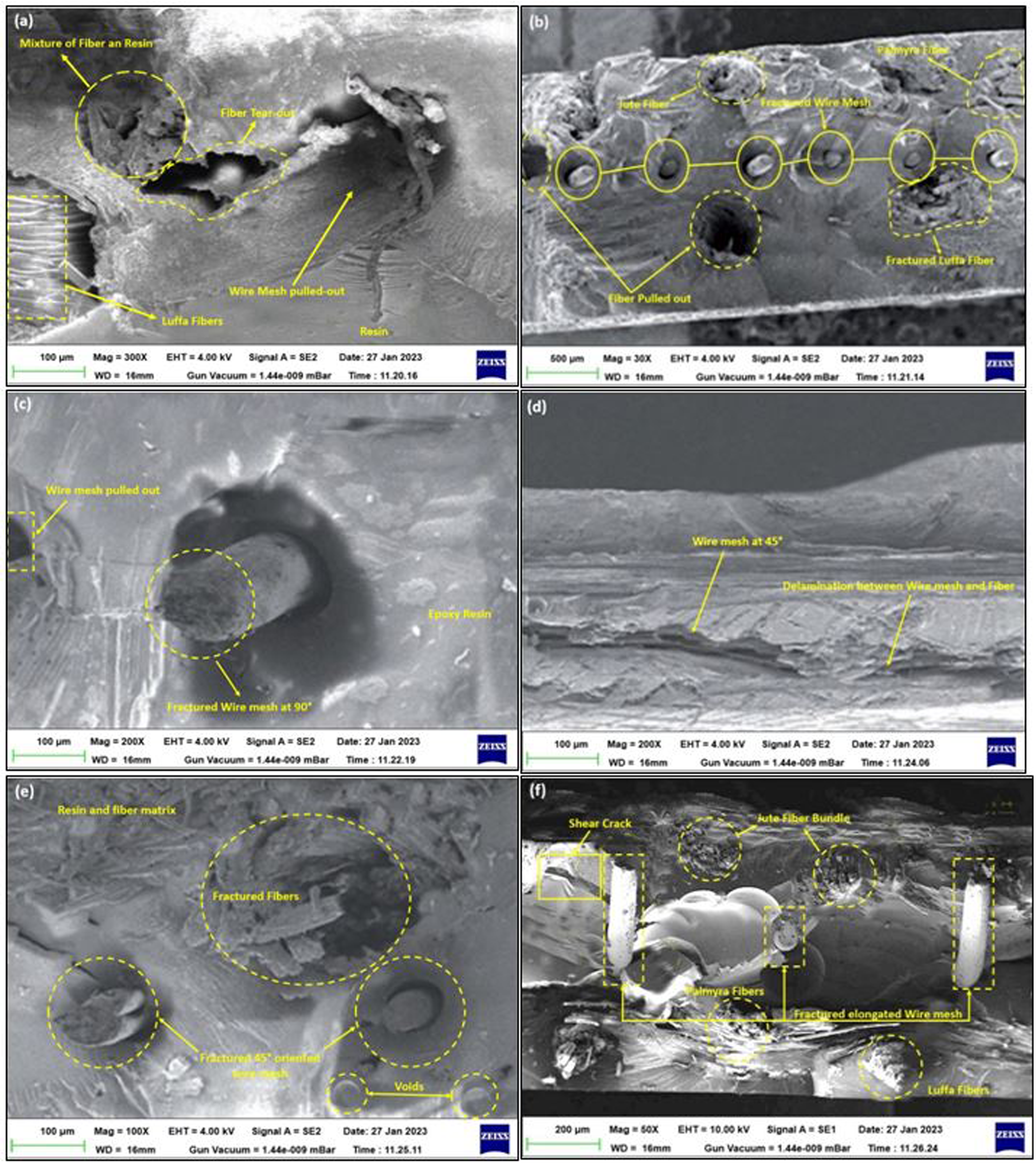
SEM image of fiber failure of 90° wire mesh-oriented sample (a) to (c) and 45° wire mesh oriented (d) to (e) and (f) impact tested sample.
Alternatively, when the wire mesh is oriented in the longitudinal direction, it exhibits a cleavage mode of failure, as depicted in Figure 40(d) to (f). Fracture surface analysis is performed to examine interfaces, debonding, wire mesh behavior, and fiber pull-outs. In the examined samples, fiber pull-out and fiber breakage are observed only in localized areas, as shown in Figure 40(a) to (f), indicating a strong interface between the fiber and matrix. The Charpy impact test reveals the failure of the fiber and wire mesh, as shown in Figure 40(f). The fiber breakage exhibits a brittle nature without fiber pull-out, and a slight bending is observed along the length of the wire mesh.
Conclusion
In this study, the mechanical behavior of wire mesh hybrid composites with 45° and 90° orientations is investigated through tensile, flexural, impact, hardness, ILSS, and DMA analysis. Additionally, water absorption and SEM examination are conducted to further assess the properties of the composites. The following outcomes are presented below:
The flexural strength of the 45° oriented wire mesh hybrid composite sample is 35% higher than that of the 90° wire mesh orientated sample. Additionally, an increased deflection of 36% is seen in the 45° orientated wire mesh sample. The wire mesh reinforcement greatly improved the composite's delamination toughness. Energy absorption is 29 percent higher for the 45° oriented wire mesh composite compared to the 90° oriented wire mesh composite. The maximum Impact strength 38.4 kJ/m2 was observed in specimen group name “5” (45° wire mesh-oriented composite), which was 11% more than that of same group name “5” composite with 90° wire mesh-oriented composite. The 45° oriented 5′ wire mesh composite has a larger storage modulus (50.71 GPa) and lower loss modulus (1.5 GPa) in the glassy state at a frequency of 0.5 Hz. High damping factor (0.820) at 0.5 Hz frequency is achieved by specimen group “5” with 90° orientated wire mesh composite in the transition region. Due to the lower value of the effectiveness constant, the wire mesh composite that is oriented at 45° is found to be the most effective at reinforcing. Water absorption behavior of 45° and 90° wire mesh orientation sample are almost same for the case of “5” group composite. Only distilled water showed the maximum water absorption 8% and 51% higher than as compared to normal and salt water respectively for the same days.
Substantially, various study results indicate that the mechanical and DMA properties of the 45° oriented wire mesh composite (5′) in the “5” sample group are superior to those of the 90° oriented wire mesh composite (5″).
Footnotes
Authors’ contributions
Mukesh Kumar Nag: Conceptualization, investigation, methodology, writing original draft. Parmanand Kumar: Conceptualization, investigation, methodology, writing review, editing, and supervision.
Declaration of conflicting interests
The authors declared no potential conflicts of interest with respect to the research, authorship, and/or publication of this article.
Funding
The authors received no financial support for the research, authorship, and/or publication of this article.