
Abstract
To overcome the inherent limitations of the ceramic matrix composite (CMC) process and increase the torque capacity of CMC torque tubes, this study investigated the failure causes of 2D woven chemical vapor infiltration (CVI) C/SiC and SiC/SiC combined CMC torque tubes. The CT test was used to describe the non-homogeneous density distribution of the CMC torque tubes. Using the Archimedes drainage method to evaluate density and porosity, we simulated the stress distribution and failure strength of CMC torque tubes using an FEM model. Fixtures suitable for universal material testing apparatuses were used for CMC torque tube torsional tests. The stress-strain curves showed that two distinct fiber types of CMC torque tubes displayed different torsional tendencies, and we examined the main causes of failure. The SiC fiber in the CMC torque tube increased maximum shear stress and modulus. Additionally, the strength of the SiC/SiC torque tube, rather than the interface between the C/SiC and SiC/SiC torque tubes, was the primary cause of combined CMC torque tube failure.
Introduction
With the rapid development of ceramic matrix composites (CMC), there has been a growing interest in their structural applications, such as tubes, which have been considered for use in fusion and nuclear reactors. 1 Understanding the mechanical response and failure behavior of CMC tubes is crucial for designing structural components in nuclear reactors. Gao et al. found that CMC tubes have good energy absorption capacity and stability under load-bearing processes. 1 Yu et al. studied the cyclic tensile test method to evaluate the mechanical properties of SiC/SiC pipes and established the deformation-strain relationship through experimental and simulation methods. 2 Lee et al. optimized the testing fixture for circular tensile testing of C/SiC composite pipes using fiber winding technology to avoid premature damage caused by bending stress. 3 Liao et al. investigated the tensile and torsional tests of woven CMC composite pipes, and this method and gripping equipment can be extended for biaxial loading situations. 4 Due to frequent use at high temperatures, Mubina et al. studied the oxidation resistance of Cf/C-SiC tubes and compared the oxidation behavior of three samples from room temperature to 1450°C using experimental methods. 5 They found that SiC coated samples had the highest oxidation resistance.
However, composite pipes possess highly dispersed properties and complex failure modes, which require further research. Teng et al. investigated the effect of off-axis angle on the tensile deformation and failure behavior of plain woven C/SiC. They characterized the deformation distribution using digital image correlation and found that the off-axis angle influences the fracture location of each layer. 6 Liu et al. studied the mechanical response and damage mechanism of 2D SiC/SiC ceramic matrix composites under tension shear coupling loads through experimental methods. Their work revealed that the tension-shear coupling load can affect the damage evolution, damage form, and macroscopic performance of the composite. 7
To further clarify, composite materials are used in a wide range of applications due to their unique properties. Thick section ceramic matrix composites, in particular, have the potential for use in high-temperature applications like gas turbines, aerospace components, and nuclear reactors. However, the non-uniformity present in these composites can lead to failure and a decrease in their overall performance. Zhang et al. addressed this by developing a mechanical assisted CVI method to prepare thick cross-section 2D C/SiC composite materials. This process helped to alleviate the non-uniformity of the composite material and improve its overall performance. 8 The researchers also investigated the effect of diffusion-enhanced pores on the densification process and studied the relationship between density and other parameters. 9 The microstructure and tensile properties of the composite were also studied in detail. This included analyzing parameters such as load-displacement curve, fracture work, tensile strength, and tensile stiffness. 10 Moreover, the deposition of the matrix was adjusted using diffusion assisting holes for 3D needed C/SiC, and the mechanical properties, such as fracture work, fracture strain, and bending stress, were studied. All these findings can help in developing homogenization reinforcement methods for thick section composite materials. 11
The torque capacity of torque tubes needs to be increased, and several scholars have investigated the use of thick-walled torque tubes. Carter proposed a method to characterize the ply-level properties of ceramic matrix composite (CMC) tubes. 12 They indicated that due to fabrication differences, most tubular samples of ceramic matrix composite materials can’t be represented by planar samples for characterization. However, they did not specifically study the heterogeneity and microstructure performance. Li et al. studied the torsional behavior of C/SiC pipes, considering the effects of structural parameters. 13 Their finite element model assumed a homogeneous SiC matrix, which may not be uniform if the infiltration of SiC is not consistent. Therefore, previous studies considered the bottleneck effect of the chemical vapor infiltration (CVI) process, and a heterogeneous FEM method was suggested.14,15 It was reported that the thickness of 2D woven torque tubes should not be too large, making it challenging to produce large-scale CMC torque tubes. To address this issue, a plan was proposed to combine two types of CMC torque tubes: one C/SiC tube and one SiC/SiC tube. The SiC/SiC tube should be located on the outer portion due to the torsional stress distribution of the 2D woven torque tube, which increases with the radius.
This paper investigates the combined C/SiC and SiC/SiC CMC torque tube and proposes a new design concept and a novel C-fabric connection process method to overcome the inherent defects of the CVI process in manufacturing thick-walled structures. By preparing a uniformly thick-walled composite material torque tube using the combined C/SiC and SiC/SiC CMC materials, the torque capacity can be increased while reducing costs. The failure behavior of this torque tube was analyzed using experimental methods and finite element analysis.
Experimental procedure
Specimens
2D woven C fiber and SiC fiber were used as the reinforcement for the 2D C/SiC and SiC/SiC torque tubes. A pyrolytic carbon (PyC) layer was deposited on the surface of the fibers to serve as a fiber/matrix interface, which helps to weaken the interfacial bonding. The SiC matrix was then introduced by isothermal chemical vapor infiltration (CVI) method. In the CVI process, methyltrichlorosilane (MTS, CH3SiCl3) was used to transport SiC into the preform, with H2 as the carrier gas. The nominal conditions for the matrix deposition were 1100°C, an H2 : MTS ratio of 10 : 1, and a pressure of 4 KPa. To fabricate the combined torque tube, prefabricated C/SiC and SiC/SiC composite torque tubes with appropriate diameters were prepared using the CVI method. Then, the SiC/SiC torque tube was sleeved on the outside of the C/SiC torque tube to form a combined torque tube. Carbon cloth was used as an interlayer, and the entire composite torque tube was subjected to CVI to form the final structure.
The three test specimens, C1, C2, and C12, were specifically designated. C1 and C2 CMC torque tubes were reinforced with C fiber and SiC fiber, respectively. In contrast, the combined CMC torque tube, C12, was composed of both C and SiC fibers. After the appropriate amount of CVI, the dimensions of the CMC torque tubes were adjusted mechanically. The C1 and C2 CMC torque tubes were 240 mm in length, 80 mm in outer diameter, and 5 mm in thickness. The C12 CMC torque tube, as shown in Figure 1, was 240 mm in length, 100 mm in outer diameter, and 10 mm in thickness. The inner C fiber torque tube had a thickness of 7 mm, and the exterior SiC fiber torque tube had a thickness of 3 mm.
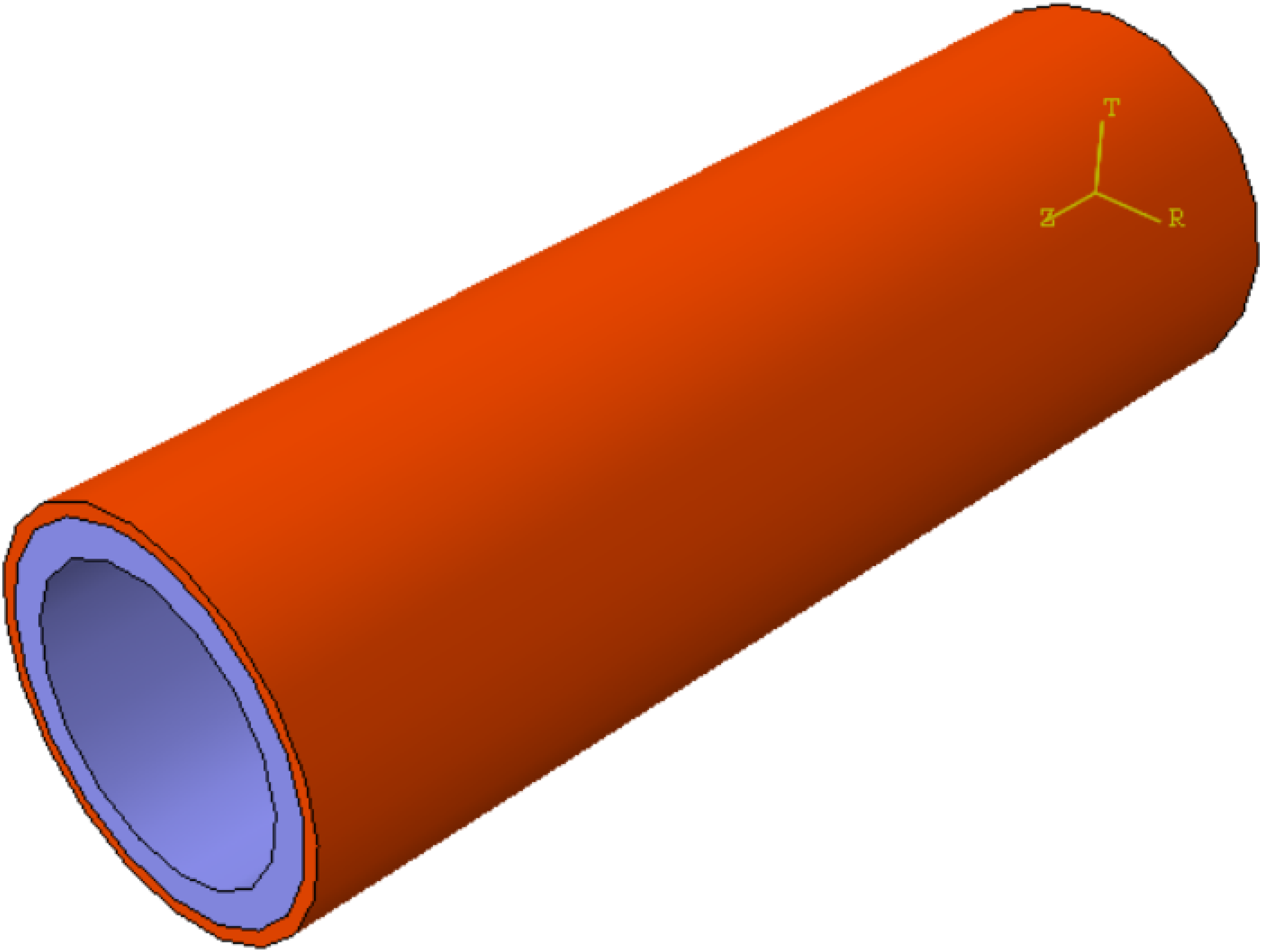
Schematic diagram of C12 CMC torque tube.
Measurements and observations
To ensure the reliability of the mechanical test sample, aluminum alloy sleeves were used to bond the exterior and inner surfaces of the two ends of the CMC torque tube. This method guarantees that the center measurement section of the CMC torsion tube will shatter, which we accept as an essential part of the testing process. To transmit torque, four pins secure both ends of the CMC torque tube (Figure 2). The elliptical shape of the pin insertion hole increases the contact area between the pins and CMC torque tube, reducing stress intensity. Torque is delivered via compression. The surface strain of the CMC torque tube is measured with three-gauge rosettes (−45°/0°/+45°), with four three-gauge rosettes (−45°/0°/+45°) positioned around the specimen in the center of the CMC torque tube, spaced 90° apart all around the circumference. These four three-gauge rosettes have a total of 12 data channels and independently gather data simultaneously for each load. A general universal testing machine (Instron1850, Instron Corp., MA, USA) provides the compression load, and the test is performed in 2 mm/min displacement control mode.
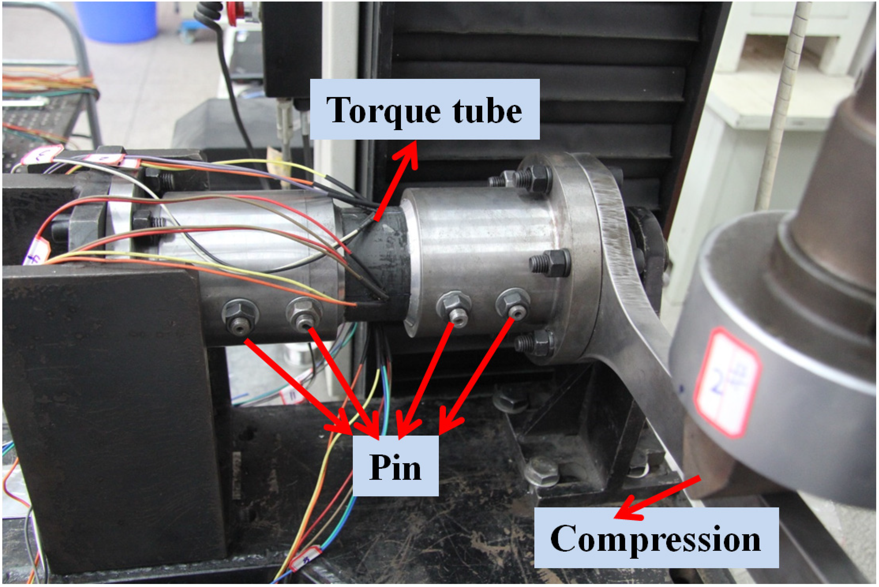
Photograph of torsion test.
The Archimedes drainage method was utilized to determine the bulk density and open porosity of the CMC torque tubes. The stress distribution of the CMC torque tube was analyzed using the finite element technique (FEM). In addition, photographs were taken to analyze the specimens’ fracture morphologies.
Results and discussion
Analysis of density/porosity
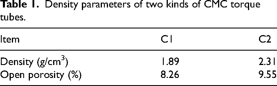
The mechanical performance of CMC torque tubes is significantly influenced by their density; therefore, it is crucial to investigate this aspect. Our study focused on two CMC torque tubes, C1 and C2, which are composed of carbon or SiC fibers and a silicon carbide matrix (PyC). Both CMC torque tubes were reinforced with the same volume fraction of fiber and PyC (40%). However, the density of the CMC torque tubes during the chemical vapor infiltration (CVI) process varies depending on the fiber type utilized. The bulk density and open porosity of the CMC torque tubes were determined via Archimedes’ method, and the density results are presented in Table 1. From the data, it becomes evident that the average density of C2 CMC torque tubes is greater than that of C1 CMC torque tubes. This difference in density may be attributed to the SiC fibers, whose increased density has a considerable influence on the CVI process.
Density parameters of two kinds of CMC torque tubes.
Due to the complex structure of CMC torque tubes compared to standard flat specimens, the Archimedes drainage method may not provide accurate density estimates. As a result, we employed X-ray computed tomography, which is a commonly used technique to analyze large assemblies. To process the CT findings, which are represented as grayscale, raw images, we used Matlab software due to their difficulty to examine visually. In the processed image, high and low densities are distinguished by the color red and blue, respectively. The advantage of using this semi-quantitative CT method is that it allows us to clearly observe the density inhomogeneity within the CMC torque tube. The CT findings display a cross-section of the ceramic matrix composite torque tube, as shown in Figure 3, with (a) representing C1 and (b) representing C2. It is evident from the image that the yellow region in C1 (composed of C fiber) takes up a significant portion of space, indicating a significantly lower density. However, the red region in C2 is more substantial. The red and outer portions of the C2 CMC torque tube suggest that the outer surface is denser than the center portion. This phenomenon can be attributed to the bottleneck effect in the CVI production process, where gas cannot enter the center due to the SiC matrix placed on the outside. To quantify this effect, we can select a line in the diameter direction of the CT image to collect density data. Figure 2 illustrates the desired location on the yellow line. The center row of density values from the Matlab image matrix is taken as the density value matrix. By utilizing the information we were able to extract from the density value matrix, we can create a curve (Figure 4) that shows the relationship between relative density and relative length. The data shows that the C1 and C2 CMC torque tubes exhibit a homogeneous density distribution due to their proper thickness. It is well known that the moduli of the SiC matrix vary with density. The presence of interlayer stress can also have a negative impact on the strength of the CMC torque tube, as various modulus matrices will exert greater stress than a homogeneous material. Therefore, the mechanical characteristics and failure behavior of the CMC torque tubes are greatly influenced by the density gradient. Nonetheless, we can consider C1 and C2 as homogeneous CMC torque tubes because the density gradient of each is not readily noticeable and has minimal effect on mechanical properties. In summary, based on our density and porosity analysis, we conclude that C1 and C2 CMC torque tubes have a rather uniform density distribution and are expected to have reasonable mechanical properties.
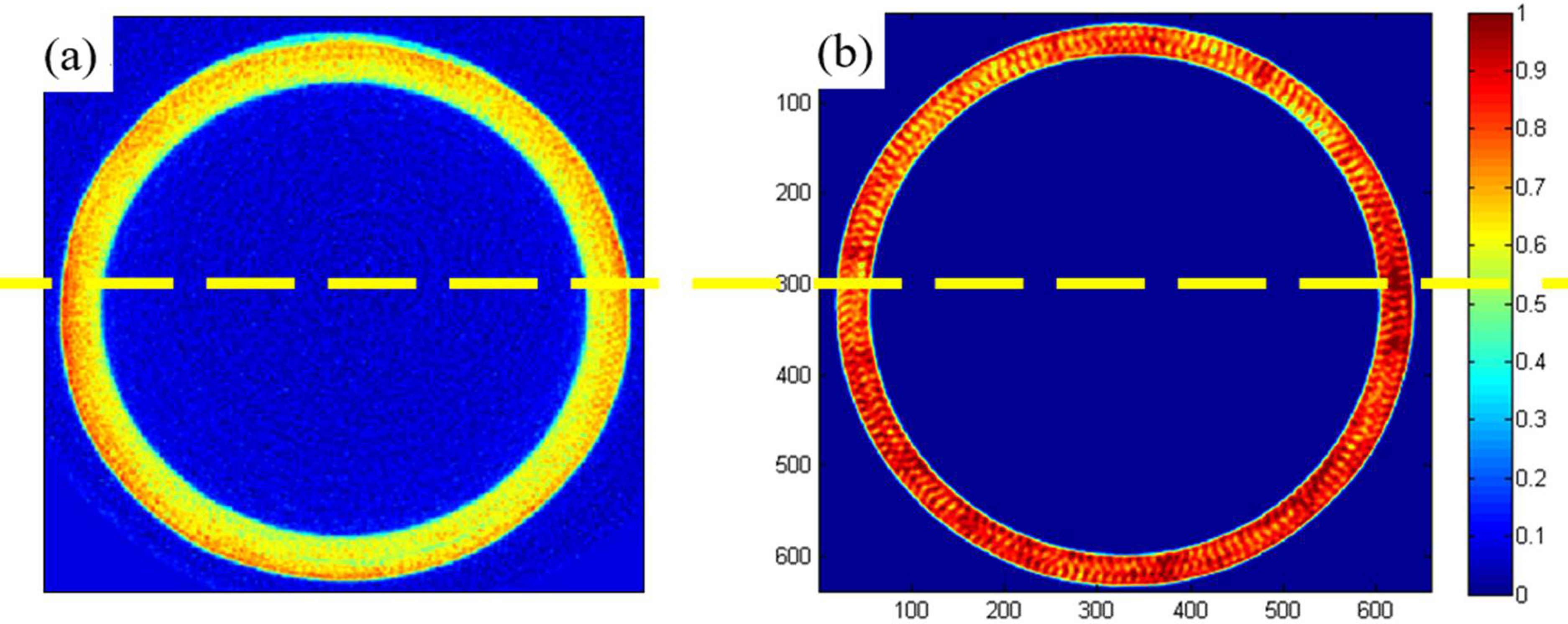
Ct results for (a) C1 and (b) C2.
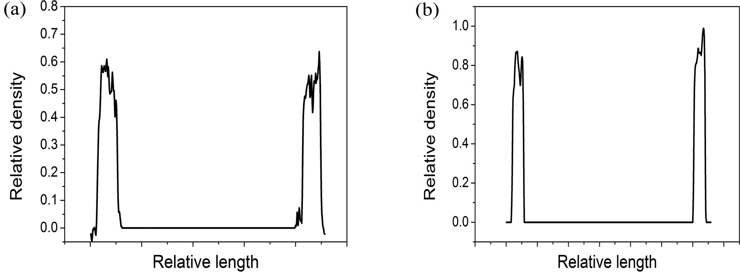
Curves of relative density-relative length for (a) C1 and (b) C2.
Simulation
To guide engineering design, it is essential to study the complete mechanical characteristics of CMC torque tubes, including their modulus, stress distribution, stress-strain curve, and failure behavior. However, due to the complex heterogeneous anisotropic nature of CMC torque tubes, an analytical approach is challenging, and a numerical approach using software such as ABAQUS® finite element technique is necessary.
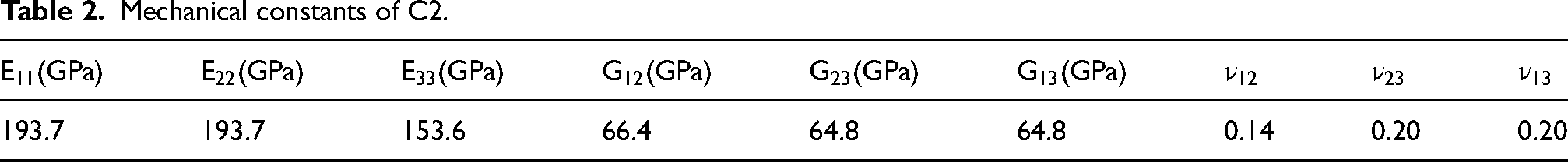
For the C1 and C2 CMC torque tubes with a uniform density distribution, the shearing stress can be determined using the isotropic torque tube formulation. To estimate the shearing stress of the C12 torque tube, we used the C3D8R element from the 3D finite element model in ABAQUS. We imposed full restriction on one end of the CMC torque tube, delivered torque at a point connected to the other end surface, and substituted sophisticated fixture equipment with common constraints to simplify the model. The C12 CMC torque tube variant was split into two pieces, with a 7 mm inner portion surrounded by a 3 mm outside portion made of different materials. The mechanical constants for the C12 CMC torque tube model were obtained from references 16 and 17.16,17 Ryshkewitch illustrated the relationship between mechanical characteristics (M) and fractional porosity as an example of how the impact of density must be taken into account.
18
Assuming total porosity instead of P, we can further study the mechanical properties of the CMC torque tubes.
Mechanical constants of C2.
Mechanical constants of C1.
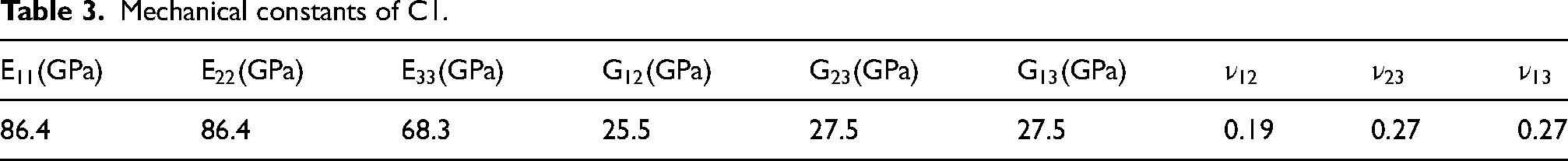
The simulation results indicate that the normal stresses S11, S22, and S33, as well as the shear stress S13, are all nearly zero. Therefore, only the shear stress (S12 and S23) is taken into consideration in the analysis. The simulation model employs a cylindrical coordinate system where numbers 1, 2, and 3 represent the radial, transverse, and axial directions, respectively. In-plane shear stress is represented by S23, while S12 refers to the interlaminar shear stress. Figure 5 presents the simulation outcomes for the distribution of shear stress (S12 and S23) in C12. The torque tube's torsion properties are consistent with an isotropic nature wherein the highest shear stress (S23) is present in the outermost region, gradually decreasing inward towards the interior regions. A correlation exists between the part's modulus and the shearing stress S23. In the case of SiC fiber CMC torque tubes, the outer part has a higher modulus and, thus, a higher S23 shearing stress. C fiber CMC torque tubes have a maximum shearing stress of approximately 70 MPa, while SiC fiber CMC torque tubes have a maximum shearing stress of 144 MPa. The interface area between the two components shows a clear S12 shearing stress, with a maximum value of 26.50 MPa. Since C1 and C2 CMC torque tubes possess an equal density distribution, their shearing strength can be determined using the isotropic torque tube formula.
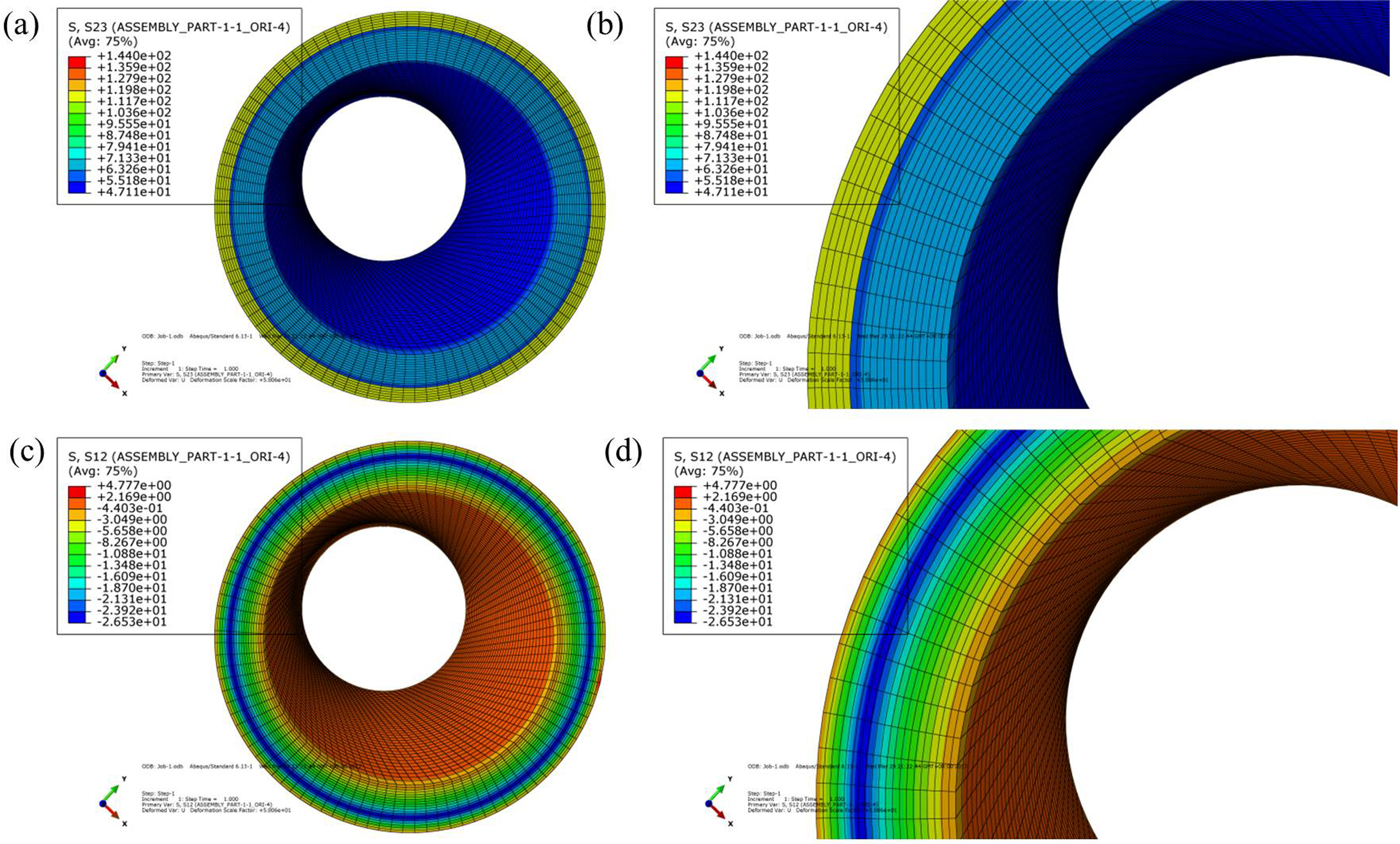
Results of shearing stress for C12 CMC torque tube (a) S23, (b) magnification of (a), (c) S12 and (d) is the magnification of (c).
The outer SiC fiber CMC torque tube in the C12 combined CMC torque tube simulation met the maximum S23 shearing stress, while the inner C fiber CMC torque tube did not. In light of this outcome, we can conclude that the outer SiC fiber CMC torque tube may fail due to the C12 CMC torque tube's failure.
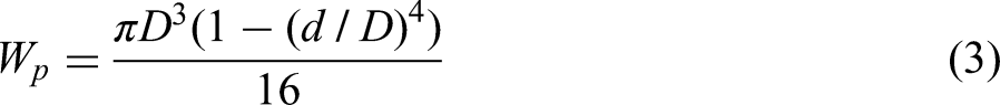
Comparison between the experiment and finite element results
The experiment used the average of four rosette measurements to calculate strain, while the shear stress was determined using the simplified isotropic torque tube formula. Figure 6 shows the torsional stress-strain curves for the C1, C2, and C12 torque tubes. The figure indicated that the modulus of the combined torque tube falls between the C/SiC and SiC/SiC torque tubes. Despite its thickness and relatively low absolute strength, the combined torque tube has a high torque capacity. As formulas (2) and (3) demonstrate, the C12 torque tube has significantly greater torque capacity with a measured torque of 7165 N·m, compared to 3651 N·m and 3948 N·m for C1 and C2, respectively. The maximum measured shearing stress S23 and simulated maximum shearing stress S23 for the C12 CMC torque tubes were 61.83 MPa and 144 MPa, respectively. Furthermore, the experimental shearing stress S12 was 0 MPa due to the lack of modulus gradient in the computation, indicating the experimental computation was not very precise. The experimental formulation is useful in straightforward application scenarios for determining the maximum shearing stress of uniform CMC torque tubes. However, in analyzing non-uniform C/SiC and SiC/SiC combined CMC torque tubes, FEM techniques must be used to create a realistic simulation model to determine the failure strength and main cause of failure.
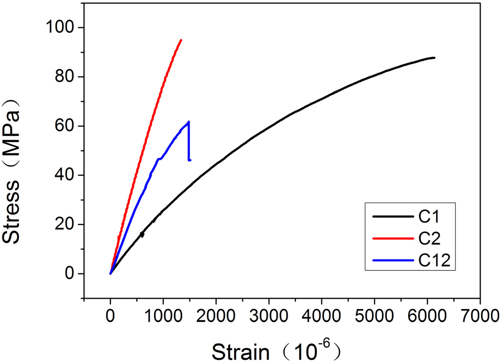
Torsional stress-strain curves of the CMC torque tubes.
C1 and C2 possess failure shearing stresses of 87.77 MPa and 94.90 MPa, respectively. C fiber CMC torque tubes show relatively low shear modulus and failure strength. The shear modulus reduces as shear strain accumulates due to damage, unlike SiC fiber CMC torque tubes, where it remains unaffected. SiC fiber CMC torque tubes exhibit higher linearity and rigidity, as evidenced by their smaller shear strain at failure compared to C fiber CMC torque tubes. This explains why SiC fiber CMC torque tubes do not exhibit significant damage before reaching failure stress.
Damage behavior
To advance the development of CMC torque tubes and simplify engineering design, a more in-depth understanding of their failure behavior is necessary. Thus, it is imperative to analyze the failure of CMC torque tubes. The failure strengths of C1, C2, and C12 CMC torsion tubes are approximately 87.77 MPa, 94.90 MPa, and 144 MPa, respectively, as shown below. SiC fiber CMC torque tubes exhibit higher failure strength compared to C fiber CMC torque tubes. Additionally, understanding the fracture mechanism and common failure modes of CMC torque tubes is critical. Figure 7 presents the macroscopic fracture morphology of the CMC torque tube. Oblique cracks are visible on the exterior of C1, C2, and C12 CMC torque tubes. Tensile failure is believed to be the dominant failure mode, with tensile stress in the 45-degree direction being the main cause of failure for CMC torque tubes.
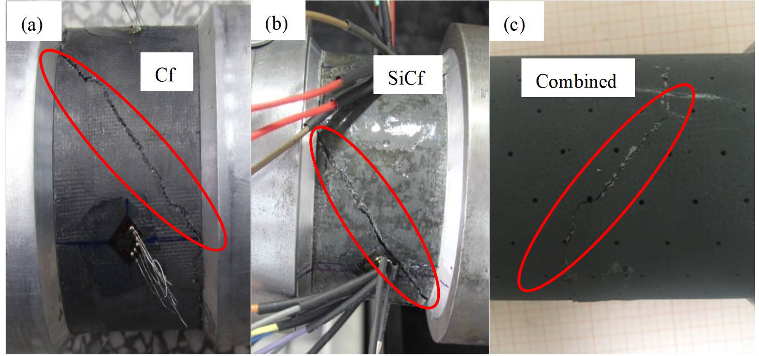
Macroscopic cracks of (a) C1, (b) C2 and (c) C12.
Conclusions
Since there is no practical way to accurately depict the actual CMC torque tubes, the finite element approach and experimental methods were used for characterizing them at ambient temperature. The simulation approach should be used to examine the C/SiC and SiC/SiC combined CMC torque tubes because the experiment demonstrated that SiC fiber has a higher torque capacity and shear modulus than C fiber.
The combined CMC torque tube made of C/SiC and SiC/SiC has a shear failure strength of 144 MPa and a torque capacity of 7165 N·m. It overcomes the problem of SiC matrix density reduction and unevenness caused by excessive thickness, and greatly improves the limit torque compared to a single CMC torque tube. Failure analysis of C/SiC and SiC/SiC combined CMC torque tubes indicates that the failure mode is tensile and the predominant failure factor is the tensile stress in the 45-degree direction of the external SiC fiber moment tube. This research explores the feasibility and torsional performance of the combined CMC torque tube for the first time and further extends its engineering applications.
Footnotes
Acknowledgements
The State Key Laboratory of Solidification Processing (NWPU), China, and the Creative Research Foundation of Science and Technology on Thermostructural Composite Materials Laboratory (Grant no. 6142911010304) provided financial assistance for the study, which the authors gratefully thank.
Data availability statement
The data that support the findings of this study are available from the corresponding author, upon reasonable request.
Declaration of conflicting interests
The author(s) declared no potential conflicts of interest with respect to the research, authorship, and/or publication of this article.
Funding
The author(s) disclosed receipt of the following financial support for the research, authorship, and/or publication of this article: This work was supported by the Creative Research Foundation of Science and Technology on Thermostructural Composite Materials Laboratory, (grant number 6142911010304).