
Abstract
Laser powder bed fusion, LPBF, provides manufacturing advantages, not only for complex geometry, but also for small-scale surface features. In this study, the benefit of introducing a wavy feature on the surfaces of replacement heart valves has been explored. Specifically, a new concept in exchangeable valves aims to implant a holding frame into a diseased valve such that an exchangeable valve can be implanted into the holding frame but can then be removed and replaced by another exchangeable valve as and when the first valve deteriorates. In this proposed procedure, the anchoring force between the holding frame and valve frame could be too low to prevent the valve from displacing as blood is pumped through the heart. One way in which the anchoring force could be increased is by introducing a wavy profile on the contact surfaces between the frames. In this study, a flat representation of the two frames has been used to computationally investigate the effect of wavy surface profiles on the force required to displace one frame relative to the other. The so-called pull-out force was shown to be increased by between three and five times compared to smooth surface frames, using a wave amplitude of 0.1 mm and wavelengths varying between 0.25 and 0.50 mm.
Keywords
Introduction
Transcatheter aortic valve implantation (TAVI) has become the default treatment in elderly and high/medium surgical risk patients. 1 However, the expansion of TAVI to lower risk and younger patients are increasingly bringing into focus the risks associated with bioprosthesis valve durability and the inevitable requirement for further procedures.2, 3 There is an increased likelihood that younger patients, in particular, will require a second or third valve intervention as a consequence of bioprosthetic valve degeneration. 4 However, repeat percutaneous aortic valve implantations inevitably introduce the challenges of (a) shrinking of the annular diameter, resulting in a reduced valve flow area and (b) potential obstruction of the coronary arteries. 5 In order to overcome these disadvantages, Eren et al. and Bressloff and Curzen have developed an exchangeable valve concept,5, 6 in which a permanent holding frame is deployed to open a diseased native valve, thus providing a prosthetic annulus as a platform for the deployment and subsequent replacement of an exchangeable prosthetic valve element. The schematic in Figure 1(a) shows the concept.
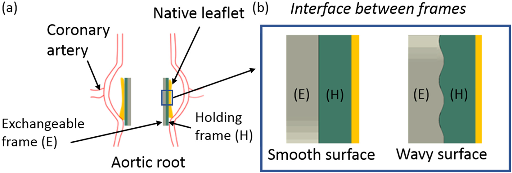
(a) Exchangeable valve concept in the aortic root and (b) interface profiles between the exchangeable frame and the holding frame.
Whilst the holding frame can be assumed to be securely anchored in place through direct contact with the native valve leaflets, as in a contemporary valve implantation procedure, the exchangeable valve is in contact with the holding frame. As such, the contact force between the frames could be too low to avoid unwanted displacement of the prosthetic valve when exposed to the antegrade forces produced by the beating heart. Resistance to frame displacement is a function of the friction between the contact surfaces, combined with the radial forces (RF) exerted by the prosthetic valve. 7 This preliminary study demonstrates how resistance to frame displacement can be enhanced by a wavy profile interface between the frames, as shown in Figure 1(b). Key to the effectiveness of the wavy surface feature is the fact that the force required to displace the exchangeable frame has to reduce the radius of the frame to overcome the RF. The secondary contribution acts through the increased surface area produced by the wavy surfaces.
Typically, replacement heart valve frames are manufactured via traditional laser cutting from a tube. Now, the feasibility of manufacturing biomaterials 8 including these type of thin strut frames 9 is being assessed using laser powder bed fusion (LPBF) and we are further exploring the possibility of exploiting LPBF to produce the proposed wavy surface profiles.
Contact surface design and computational model setup
Assessment of the effect of wavy surface features was conducted by setting up a flat representation of a circular holding frame and valve frame system. The holding frame, as shown in Figure 2(a), was inspired by the patent of Bressloff and Bailey, 7 comprising a layered configuration, designed to not change length during deployment. The exchangeable frame was based on the SAPIEN3 valve (Edwards Lifesciences, USA), as shown in Figure 2(b). Exploiting circular symmetry, one-twelfth of these geometries were represented in the flat model, as shown from above and the side in Figure 2(c). Wave profiles, constructed as shown in Figure 2(d), were added to the internal surface of the holding frame and the outer surface of the exchangeable frame. The wave profiles were constructed from a symmetrical sawtooth outline, filleted with a radius of 0.2 mm and the wave amplitude, given by the height of the sawtooth triangle was fixed at 0.1 mm. Wave numbers of 20, 30, 35 and 40 were analysed, equivalent to wavelengths of 0.5, 0.33, 0.29 and 0.25 mm, respectively. Simulations were performed in Abaqus Explicit. The material properties were based on the LPBF 316L stainless steel from Croft AM (UK): density of 7.9 g/cm3, Young's modulus of 132.483 GPa, Poisson's ratio of 0.3 and damping alpha’s factor of 6283. Figure 3 shows the material properties in the plastic stage. For the boundary conditions, the bottom surface of the holding frame was fixed – Figure 2(e) – and a pressure loading was applied on the top surface of the exchangeable frame – Figure 2(f) – based on a mid-range RF of 50 N. 10 To assess the pull-out force needed to displace the exchangeable frame, a concentrated force was applied on all nodes on the top surface of the exchangeable frame – Figure 2(g) – in a direction parallel to the frames and summing to the total specified pull-out force. The coefficient of friction was assumed to be 0.2.
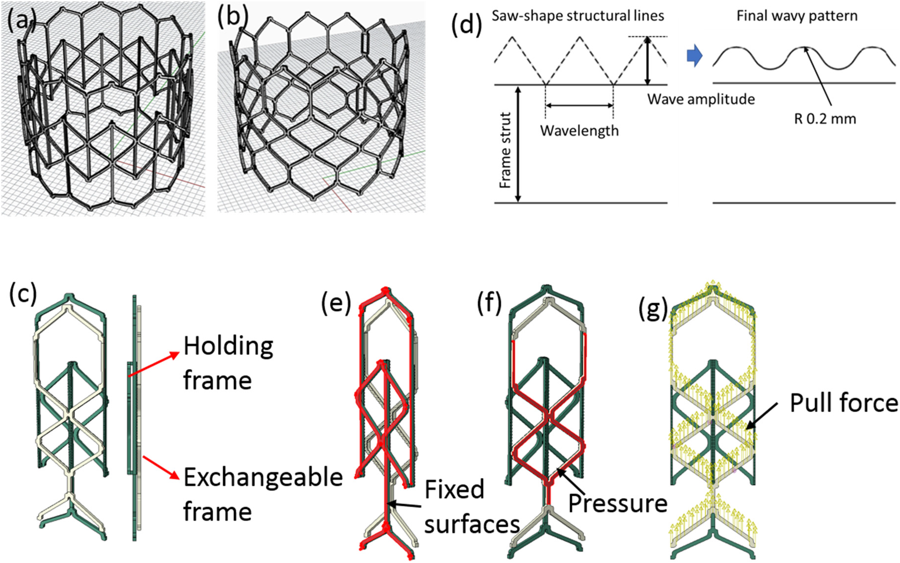
(a) Holding frame geometry, (b) exchangeable frame geometry, (c) assembly of flat, one-twelfth size frames for simulation, (d) key features of the wavy surface, (e) holding frame boundary condition, (f) exchangeable frame radial forces (RF) boundary condition and (g) exchangeable frame pull-out force.
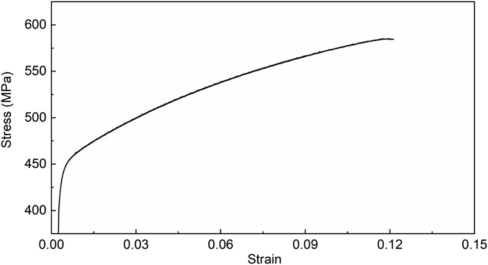
True stress–strain curve of the plastic stage (based on Croft AM 316L stainless steel samples).
In all cases, a two-step simulation was performed with the RF applied to the top surface of the exchangeable frame in the first step, linearly increased in a time period of 0.01 s, to a peak value equivalent to one-twelfth of the 50 N RF of a complete 12-cell frame. In the second step, the RF was maintained and the pull-out force was increased to its target value for a time period of 0.1 s and then held for another 0.1 s.
Results and discussion
To determine the pull-out force needed to displace the exchangeable frames, the displacement of a test node (highlighted in Figure 4(a)) at the end of the exchangeable frame was measured. Initially, a series of baseline simulations were conducted for the non-wavy surface frames. Figure 4(b) shows the variation of displacement of the test node with time for pull-out forces varying between 6 and 20 N. When the pull-out force was 6 or 8 N, the displacement of the test node remained below 0.01 mm, effectively indicating that the frames didn’t move. It is only at 12 N that the exchangeable frame is clearly shown to have overcome the resistive frictional force to produce significant movement. Figure 4(c) shows the displacement-time graph of the test node for a wavy surface simulation with the largest wavelength of 0.5 mm. Now, significant movement only occurs at pull-out forces above 33 N. The variation of displacement with pull-out force for a range of different wavelengths is summarised in Figure 4(d). Individual points indicate the final displacement of the test node for specific pull-out forces for each surface design. With the wavy surface designs, the curves shift rightwards significantly, indicating the increase of force needed to move the exchangeable frame. Further, the pull-out force increases as the wavelength decreases. Figure 4(e) compares the final deformed wavy surface frames under different pull-out forces for a wavelength of 0.25 m. In the left-hand panel, for a pull-out force of 48 N, the wave peaks on the exchangeable frame are unable to pass over the peaks on the holding frame. Effectively, for this pull-out force, the wavy profile prevents the exchangeable frame from achieving sufficient displacement normal to the direction of the pull-out force so as to overcome the applied RF. With a higher pull-out force of 49 N, the exchangeable frame is able to overcome the RF and the peaks can move over the peaks on the holding frame, as shown in the right-hand panel of Figure 4(e). In all cases, the pull-out force, Figure 4(f), was set as the minimum pull-out force required to maintain continuous displacement of the exchangeable frame relative to the holding frame. The pull-out force for the non-wavy surface frames was 9.95 N. Midha et al. 11 reported that the pull-out force of the SAPIEN XT frame from a glass aortic chamber was between 5.54 and 7.09 N. The pull-out force of 32.4 N for the 0.5 mm wavelength frames was approximately three times the pull-out force for the non-wavy surface frames. As the wavelength reduces, the pull-out force increases to a maximum value of 48.2 N for the 0.25 mm wavelength, equivalent to nearly five times the pull-out force required for the non-wavy surface.
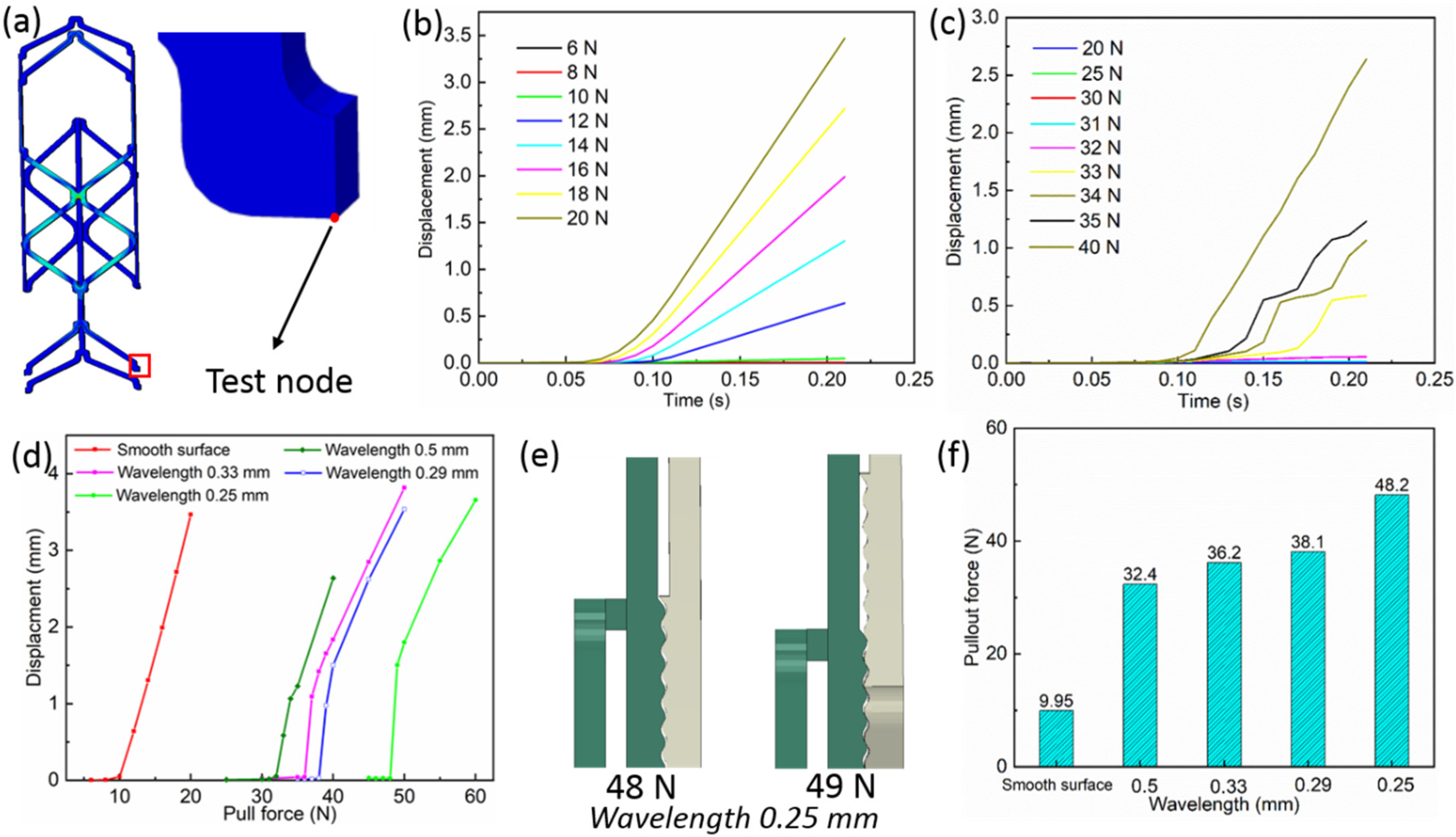
(a) The chosen test node on the exchangeable frame. Displacement versus time of the test node in (b) the non-wavy surface simulations and (c) the 0.5 mm wavelength simulations. (d) Final displacement of the test node versus pull-out force for different wavelengths. (e) The final deformed frames for pull-out forces of 48 N (left) and 49 N (right) for the 0.25 mm wavelength simulations. (f) Pull-out forces for each case as determined from (d).
The introduction of wavy profiles to the contact surfaces between two frames increases the force required to move the exchangeable frame relative to a fixed holding frame. Ultimately, however, the resolution of LPBF technology will limit the dimensions of the proposed wavy surfaces. Encouraged by our computational results, preliminary LPBF samples have demonstrated promising results, as shown in Figure 5, obtained from a scanning electron microscope (SEM) of a non-wavy strut and a wavy strut with a wave amplitude of 0.1 mm.
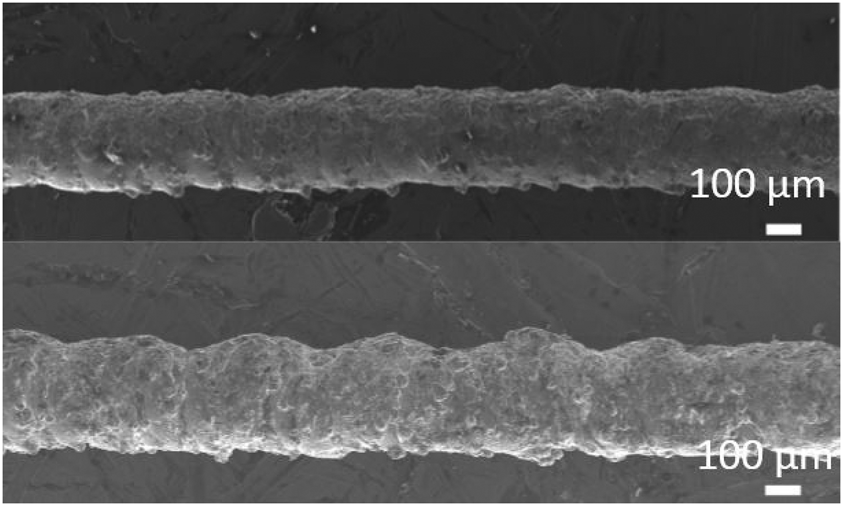
Scanning electron microscope (SEM) images of a non-wavy strut (upper panel) and a 0.1 mm amplitude wave on the upper surface (lower panel). In both cases, the upper surfaces have been sand blasted.
Conclusion
A novel wavy surface feature has been proposed to improve the anchoring performance for an exchangeable heart valve replacement concept. Using a simplified representation of the concept, a wave amplitude of 0.1 mm and wavelengths equal to 0.50, 0.33, 0.29 and 0.25 mm, demonstrated that the force required to generate axial movement can be increased by approximately three to five times, across this wavelength range, compared to non-wavy surfaces.
Footnotes
Declaration of conflicting interests
The author(s) declared no potential conflicts of interest with respect to the research, authorship, and/or publication of this article.
Funding
The author(s) disclosed receipt of the following financial support for the research, authorship, and/or publication of this article: This work was supported by the Engineering and Physical Sciences Research Council (grant number EP/S030182/1).