
Abstract
The aim of this study is to assess the interlaminar adhesion of carbon-epoxy laminates under salt water condition. Carbon-epoxy laminate specimens were immersed in a salt water tank for 60 days. Some specimens were then dried at room temperature for 280 days, until recovering their initial weight. Specimens were tested using the composite peel test, an adaptation of the floating roller peel tests for composite materials. The results showed a degradation of peel strength in some areas due to the ageing process. The drying process did not affect the test results. A scanning electron microscopic analysis carried out on the fracture surface of the specimens revealed a typical mode I failure microstructure. A mixture of matrix failure and fibre/matrix interfacial failure was observed in non-aged specimens. Finally, a chemical characterization of the fracture surfaces with energy-dispersive spectroscopy confirmed the penetration of salt water in regions near the edge of the specimens. A degradation of the fibre/matrix interface adhesion was observed in affected areas. Floating roller peel tests proved to be a fast and effective method to access the interlaminar adhesion performance of composite laminates.
Introduction
The use of composite materials has significantly increased in offshore and maritime industries aiming to reduce the weight of heavy-loaded structures but still withstand the harsh environmental conditions. Fibre-reinforced polymers (FRP) are most commonly applied due to their high strength-to-weight ratio. This technology has been developed in aerospace industry 1 and disseminated to numerous fields.2–6
In oil and gas industry composites patch repair technologies have been recently tested for the rehabilitation of damaged metallic structures subjected to marine environment.7–10 In comparison with conventional welding repairs, it turns the operation safer and avoid undesired stops of production. The repairs consist of carbon-fibre reinforced polymers (CFRPs) bonded to the pre-existing steel structure, improving the mechanical properties of the metal structure and assuring structural integrity. The expansion of this technology relies on the development of simple and reliable methods to evaluate the short and long-term performance of these materials under operational conditions.
Significant research has been carried out on the influence of long-term parameters on the performance of composites. The presence of moisture is an important issue that affects the long-term performance of composite structures. A literature review paper 11 summarized that moisture reduces mechanical properties of composite materials by one or a combination of the following mechanisms: plasticization, swelling and degradation of the matrix; damaging the fibre/matrix interface; and fibre-level degradation. It is also pointed out that drying may partially recover the strength due to the reverse effect of plasticization while the irrecoverable strength is attributed to the irreversible disruption at the interface. 12 Concerning bonded joints, moisture is responsible for swelling the adhesive and lowering its glass-transition temperature (Tg). 13 Sugiman et al. 14 verified that the mechanical properties of an adhesively bonded joint degraded in a linear way with the moisture content.
There is a vast literature on the delamination of composite materials. Fracture tests have been frequently applied in the characterization of these materials. 15 Regarding the influence of humidity, Ray 16 concluded that it is not only the absorbed moisture but also the conditions it diffuses into the specimen that characterizes the interfacial degradation phenomena. Many authors17–19 noticed that the fracture toughness of composite laminates are drastically affected by the presence of moisture. Quasi-static fracture test results showed that exposure to moisture has a bigger effect on mode II than mode I toughness. 19 Fernandes et al. 20 verified that the influence of humidity increases the brittleness of carbon-epoxy bonded joints. Alessi et al. 21 showed that mode I delamination behaviour arises from the concurrent activation of both toughening and embrittling mechanisms. Further works tested composite single 22 and double 23 lap joints. They concluded that the material properties reduce significantly after prolonged exposure to salt water as well as tap water.
It is essential to ensure good adhesion properties of bonded parts in order to avoid interface failure in service. Floating roller peel test is an effective and reliable method for evaluation of the adhesion between parts. For metal bonding, peel tests are well documented and standardized.24–27 In the case of composite materials, primary studies were performed by Teixeira de Freitas and Sinke.28,29 They exposed that when using composite peel tests, good interface adhesion results either in cohesive failure of the adhesive or intra-laminar failure of the composite, while bad adhesion results in adhesive failure.
Recently, Teixeira de Freitas et al. 30 and Arouche et al. 31 used peel tests to assess the interface adhesion of composite-to-metal-bonded joints under the effect of moisture. Specimens were chosen to simulate the failure of a composite patch repair applied in offshore units. The results proved the applicability of peel tests to study long term parameters of the joint. However, besides the failure in the bonded joint, the failure in these repairs may also occur in the composite adherend. Further studies are required regarding the effect of humidity on the interlaminar adhesion between composite layers.
In this work, carbon-epoxy laminates applied in the repair of oil and gas platforms are tested. The aim is to investigate the effect of salt water ageing and subsequent drying on the interlaminar adhesion of composite material. The application of composite peel tests to access adhesion performance of laminates is also investigated.
Experimental methods
Materials
To assess the interlaminar adhesion of the composite material, a laminate was manufactured. Carbon fibre dry fabrics with a density of 430 g/m2 were taken for the composite preparation. Each fabric is composed of two perpendicular layers of unidirectional continuous fibres [0/90]. The bi-component epoxy resin PIPEFIX® (Novatec Ltd., Rio de Janeiro, Brazil) was selected for impregnation of the laminate. The lamination process started by alternating application of fabric and resin. A thin Teflon tape was placed at the beginning of the bond line in order to provide a pre-crack.
The laminate plate consists of a rigid part with a layup of [±45]6, and a flexible part with a layup of [0/90], with [90] as the outer ply and the [0] as the contact ply with the rigid adherend. Finally, peel test specimens were cut from the laminate. The geometry is shown in Figure 1. Specimens were 25 mm in width and 250 mm long with a total thickness of 4.3 mm. The mechanical properties of the composite were determined in a previous work
30
by conducting tensile tests according to ASTM D 3039 standard.
32
Specimen geometry.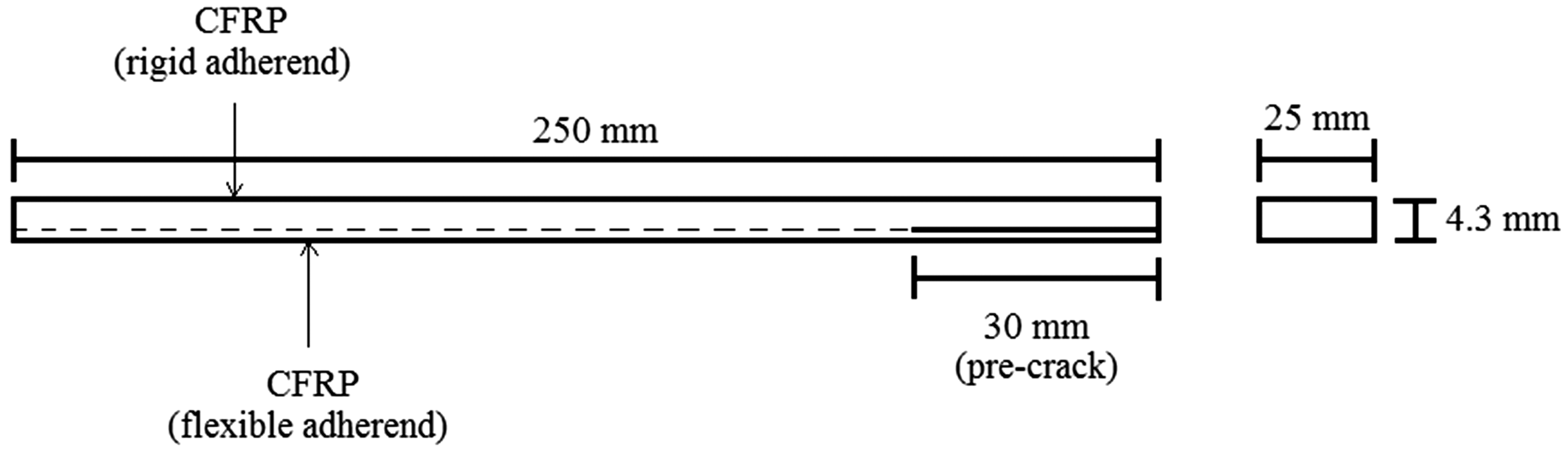
Conditioning
The salt water ageing process was employed in order to evaluate the long-term effect of harsh environmental exposure on the joint. Specimens were kept inside the salt water tank (5% NaCl) at room temperature for 60 days. The ageing process simulates the effect of environmental conditions wherein the materials are exposed to marine environment. Three reference specimens were tested without any ageing. Figure 2 shows the specimens in the salt water tank.
Specimens inside the salt water tank.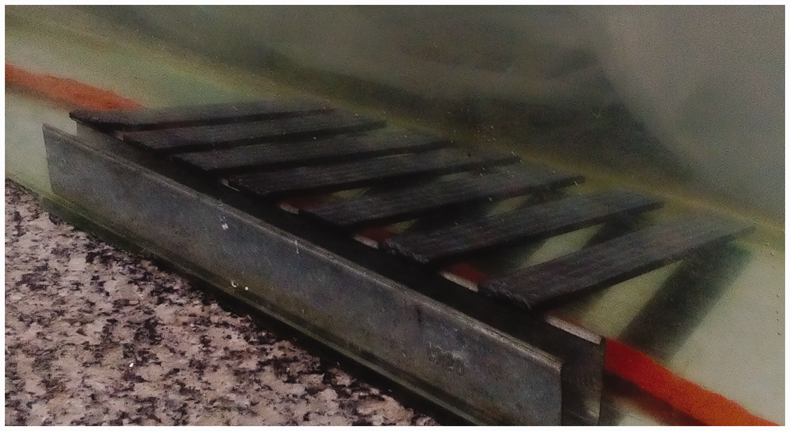
Out of the aged specimens, three specimens were tested immediately after ageing period and the remaining was kept for drying at room conditions for 280 days until the specimens recovered the initial weight.
Peel tests
The floating roller peel test allows determining the peel strength between a rigid and a flexible adherend. Tests were performed on the specimens at room conditions, by means of an electro mechanic Instron machine (Series 5966) with a maximum capacity of 20 kN, coupled with a load cell of 1 kN. The testing speed was 125 mm/min, in accordance with the Composite Peel Test.
28
During the test, the flexible adherend is peeled off from the rigid adherend. Figure 3 shows the test set up. The initial crack of the specimens was too short for clamping on the machine grips and had to be manually increased by pre-loading to enable testing. Load–displacement curves were recorded during testing. Three specimens were tested for each condition.
Floating roller peel test setup.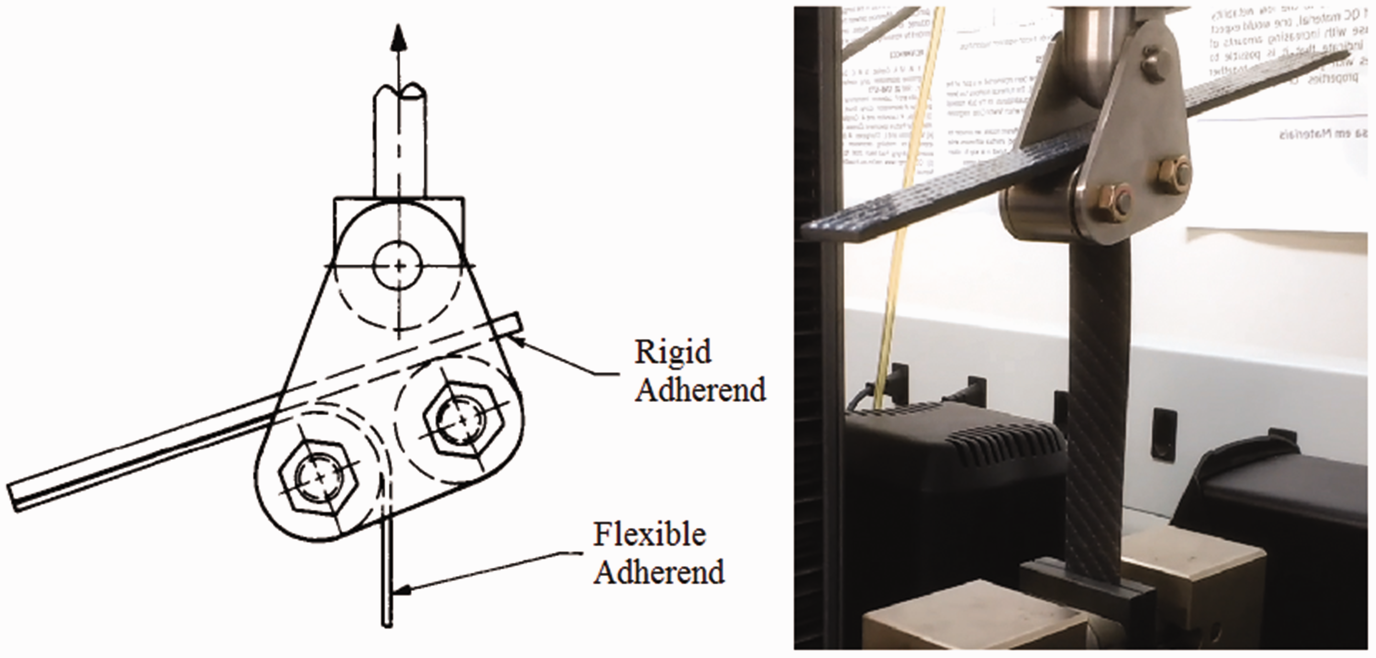
SEM analysis
A detailed SEM analysis of the fracture surfaces was performed using a JEOL JSM-7500F field emission scanning electron microscope. Prior to examination, samples were coated with a thin layer of gold (Au) and palladium (Pd) using a Quorum Q300T D sputtering system. Secondary electron images were obtained at low and high magnifications (×250 and ×1000) from regions of 2 mm from the edge and at the centre of the specimens’ width. These regions were chosen in order to reveal the penetration of salt water in the interface and characterize its effect in the fracture mechanisms under peel load. Together with the fractographic analysis, a chemical characterization of the fracture surfaces was performed with energy-dispersive spectroscopy (EDS), available in the SEM equipment.
Results and discussion
Moisture absorption
Average weight measurements of the specimens.
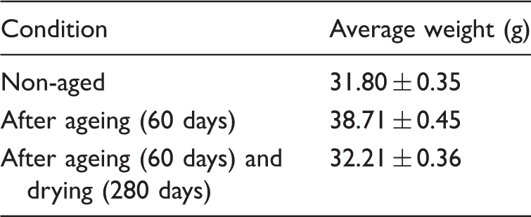
It is noted approximately 21.7% in weight uptake after 60 days of salt water immersion. It is a high value compared with past literature16–21 where high pressure manufacturing methods were applied, resulting in less than 2% of weight increase. This may be explained by the hand lay-up of the composite that produces air voids and a low fibre volume ratio. Additionally, it is observed that the specimens recovered nearly the initial weight after 280 days of drying at room conditions.
Peel loads
Specimens were tested in three different conditions: (1) non-aged; (2) immediately after 60 days ageing; and (3) after 60 days ageing and subsequent 280 days drying. Figure 4 shows the representative load–displacement curves of each test condition. Significant differences on the peel load are noted in the highlighted areas. This suggests a consequence of the ageing process. Previous work
30
showed that water ingress from the edge towards the centre of the interface and it has an irregular pattern. However, no relevant change on the peel strength is observed as consequence of the drying process.
Representative load–displacement curves of the peel tests.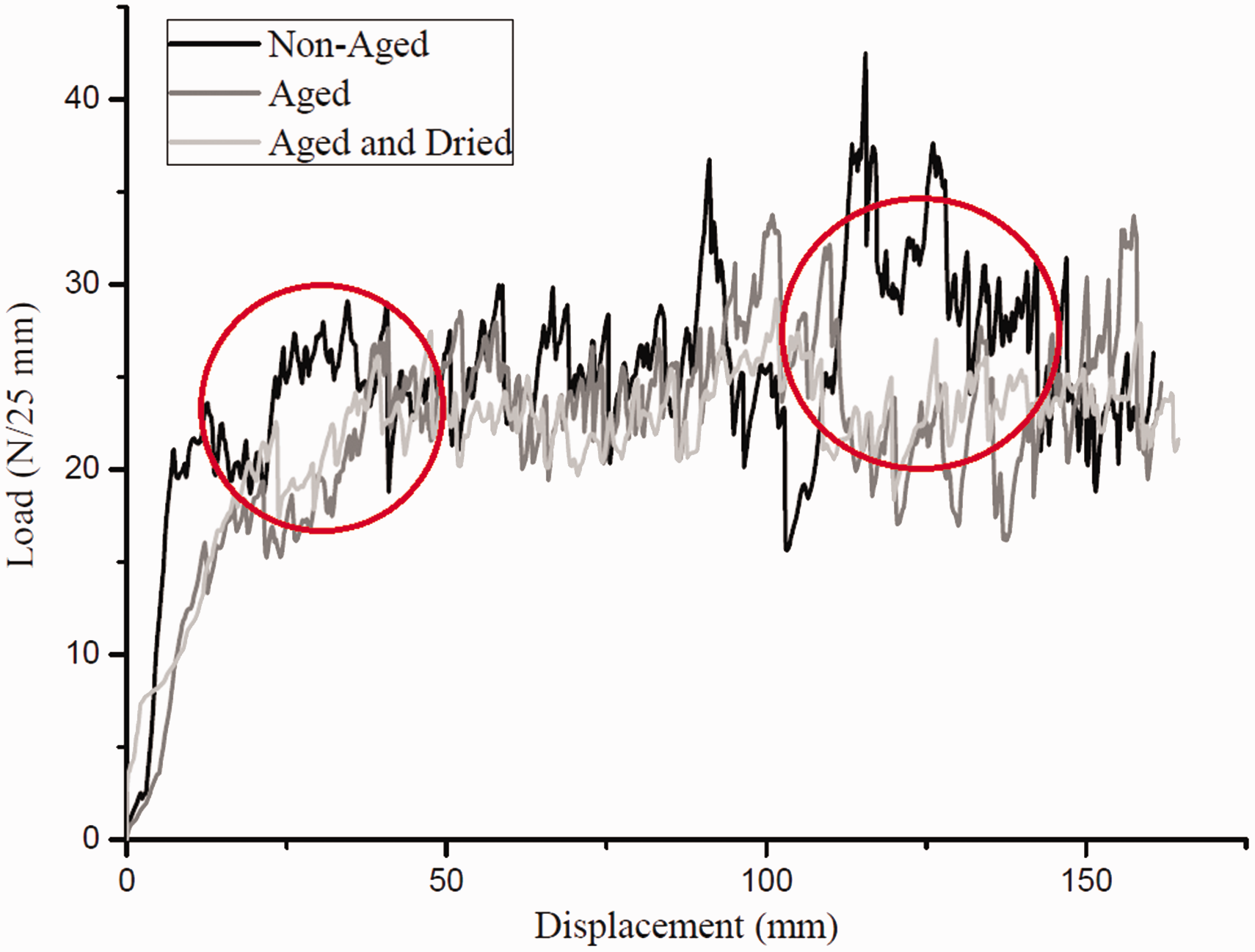
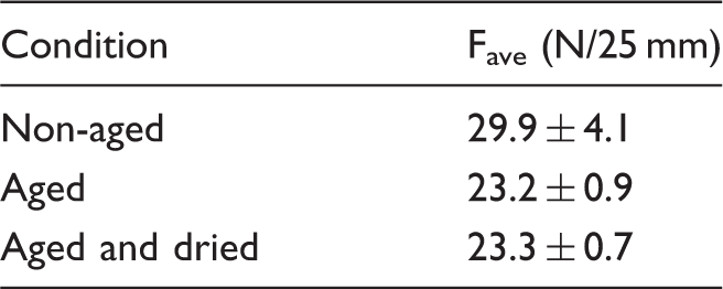
Average peel loads.
Fracture surfaces
Figure 5 shows the typical SEM fracture surfaces of samples taken from the rigid adherend in low magnification (×250, low-angle secondary electron image – LEI, 5.0 kV). The crack growth occurred from right to left direction of the images. Overall, the fracture surfaces show both resin-rich areas and exposed 0° carbon fibres. Fibres in the 0° direction are only present in the first layer of the flexible adherend. This shows that the delamination occurred predominantly at the first ply of the flexible adherend.
Fracture surfaces in low magnification: (a) non-aged – centre, (b) non-aged – edge, (c) aged – centre, (d) aged – edge, (e) aged and dried – centre, (f) aged and dried – edge.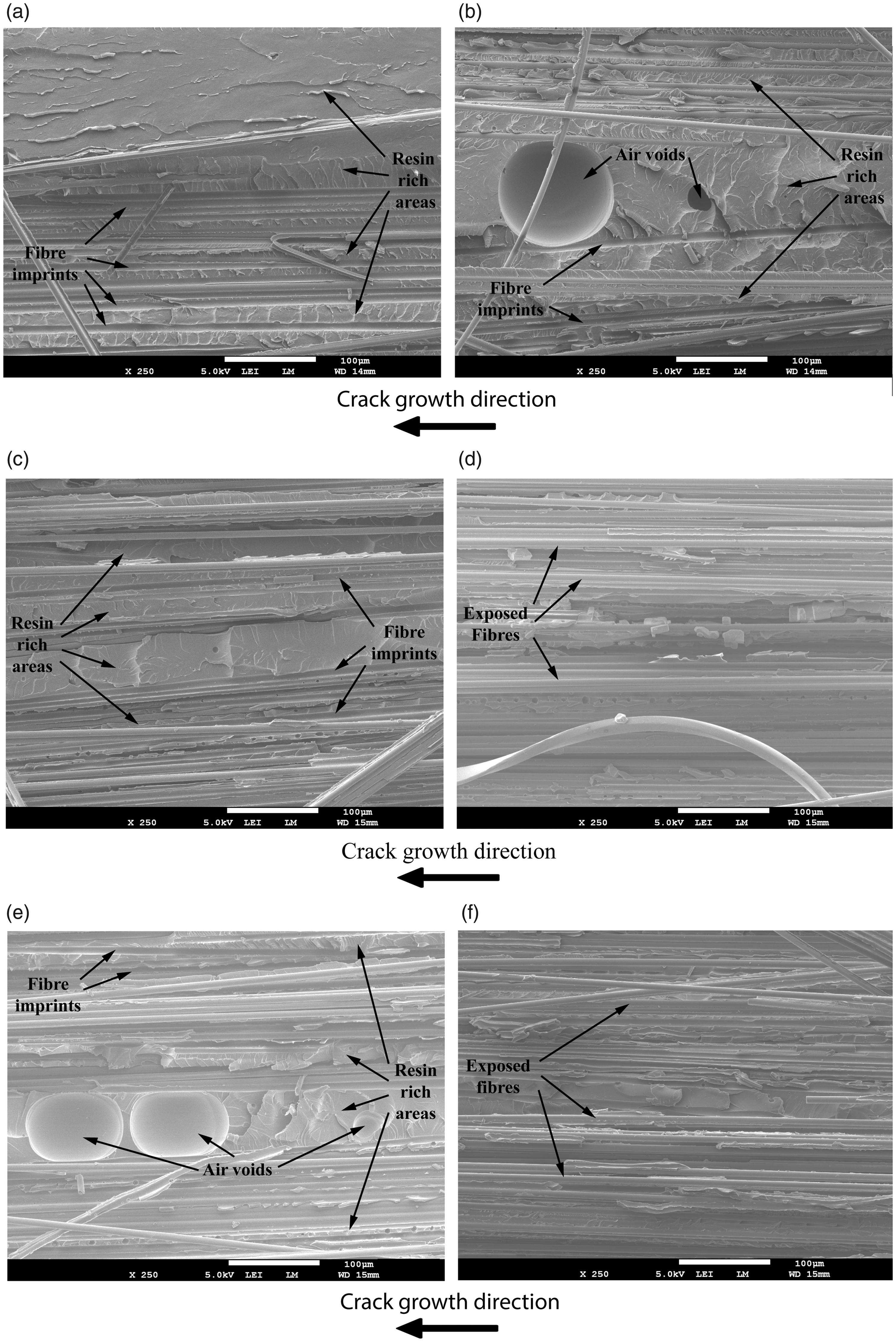
Considering the fracture surfaces of the non-aged specimens in Figure 5(a) and (b), significant resin rich areas are observed both at the centre (Figure 5(a)) of the specimens and at the edge (Figure 5(b)). The presence of considerable areas of resin together with the exposed fibres indicates that the failure occurred partially cohesive within the matrix and partially adhesive at the fibre/matrix interface.
Figure 5(c) to (f) shows the fracture surfaces of the aged specimens. The fracture surfaces at the centre locations (Figure 5(c) aged and Figure 5(e) aged and dried) show similar features as for the non-aged specimens: a mixed of matrix failure (resin rich areas) and fibre/matrix interface failure (exposed fibres). However, at the edge of the conditioned specimens (Figure 5(d) aged and Figure 5(f) aged and dried), the resin rich areas disappear and the dominant fracture feature is the exposed carbon fibres, both at the aged specimens (Figure 5(d)) and aged and dried specimens (Figure 5(f)). The corrugated shape of the fracture surfaces typical of these areas indicates a poor fibre/matrix adhesion.
Results show that fracture mechanisms at the centre of the aged specimens remained unaffected by ageing, since at these areas the fracture surfaces are similar to the non-aged specimens. The typical fracture mechanism in this case is a mixture of matrix cohesive failure and fibre/matrix interface failure. These results indicate that the edges of the fracture surfaces were affected by ageing. In these cases, the prevailing fracture mechanism is fibre/matrix interface failure. According to the literature,16,20 this is the governing damage mechanism in polymer composites exposed to environmental ageing.
Figure 6 shows the fracture surfaces obtained from the rigid adherend in high magnification (×1000, LEI, 5.0 kV). Images were taken from regions near the edge of the specimen where the effect of ageing is noted. The crack growth occurred from right to left direction of the images. Non-aged specimen (Figure 6(a)) presented a substantial amount of matrix around fibres. It indicates a strong fibre/matrix interface adhesion. In the aged specimen (Figure 6(b)), the exposed fibres are predominant. It shows that the fibre/matrix interface became the major failure mode rather than the matrix failure. A similar fracture surface is observed in the aged and dried specimen (Figure 6(c)). This confirms that the ageing process produced an unrecoverable damage in the composite interlaminar adhesion.
Fracture surfaces in high magnificatio: (a) non-aged, (b) aged, (c) aged and dried.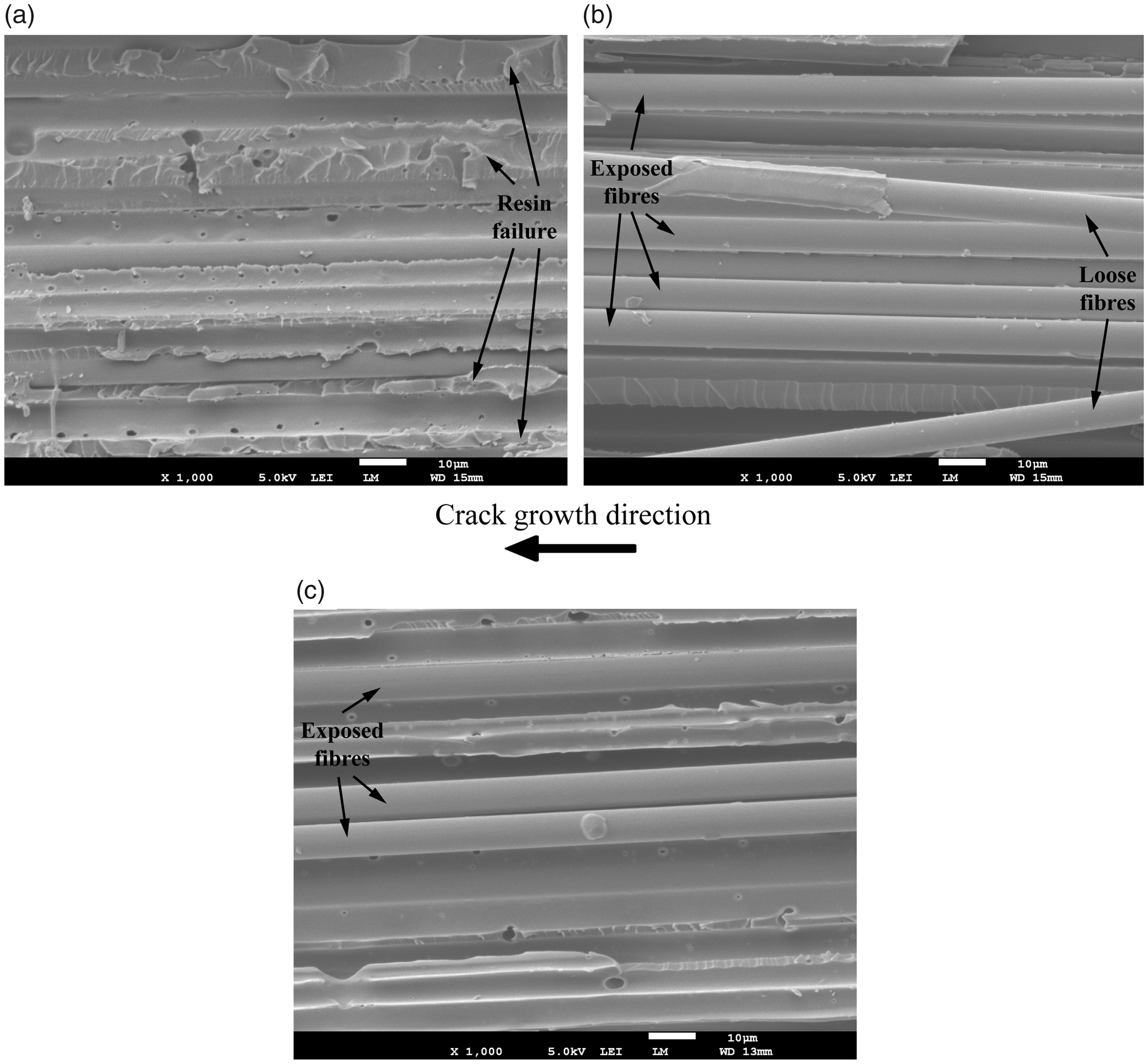
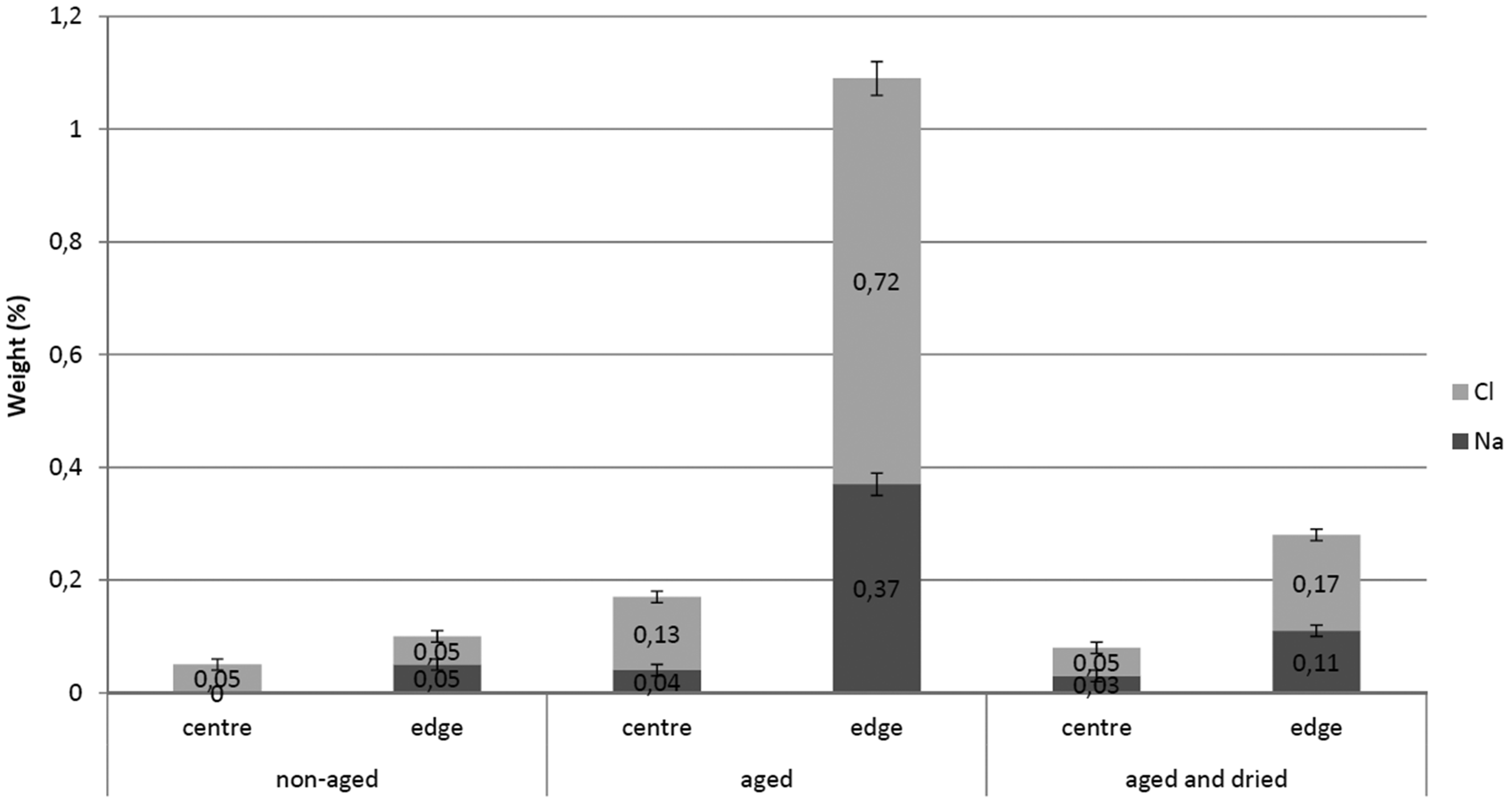
Figure 7 shows the results of the EDS analysis. The graphs display peaks that represent the occurrence of chemical elements on the fracture surface. Results revealed the presence of salt (Na and Cl elements) next to the edge of the fracture surface in aged specimen (Figure 7(d)) and in aged and dried specimen (Figure 7(f)). The incidence of these components is insignificant in both centre (Figure 7(a)) and edge (Figure 7(b)) of the non-aged specimen, as well as in the centre of the aged (Figure 7(c)) and aged and dried (Figure 7(e)) specimens. This confirms that the penetration of salt water occurred in the regions near the edge of the specimens and not at the centre. The other peaks represent the amount of carbon (C), oxygen (O) and the unnamed peaks represent gold and palladium sputtered for sample preparation. A comparative analysis of the salt content is presented in Figure 8. It is observed a decrease on the salt content at the edge of the specimen after drying. However, there was no difference between the peel loads (Figure 4 and Table 2). This reinforces the argument that the ageing process produced an unrecoverable damage on the interlaminar adhesion of the composite.
EDS spectrum of the fracture surfaces: (a) non-aged – centre, (b) non-aged – edge, (c) aged – centre, (d) aged – edge, (e) aged and dried - centre, (f) aged and dried – edge. Salt content on the fracture surfaces.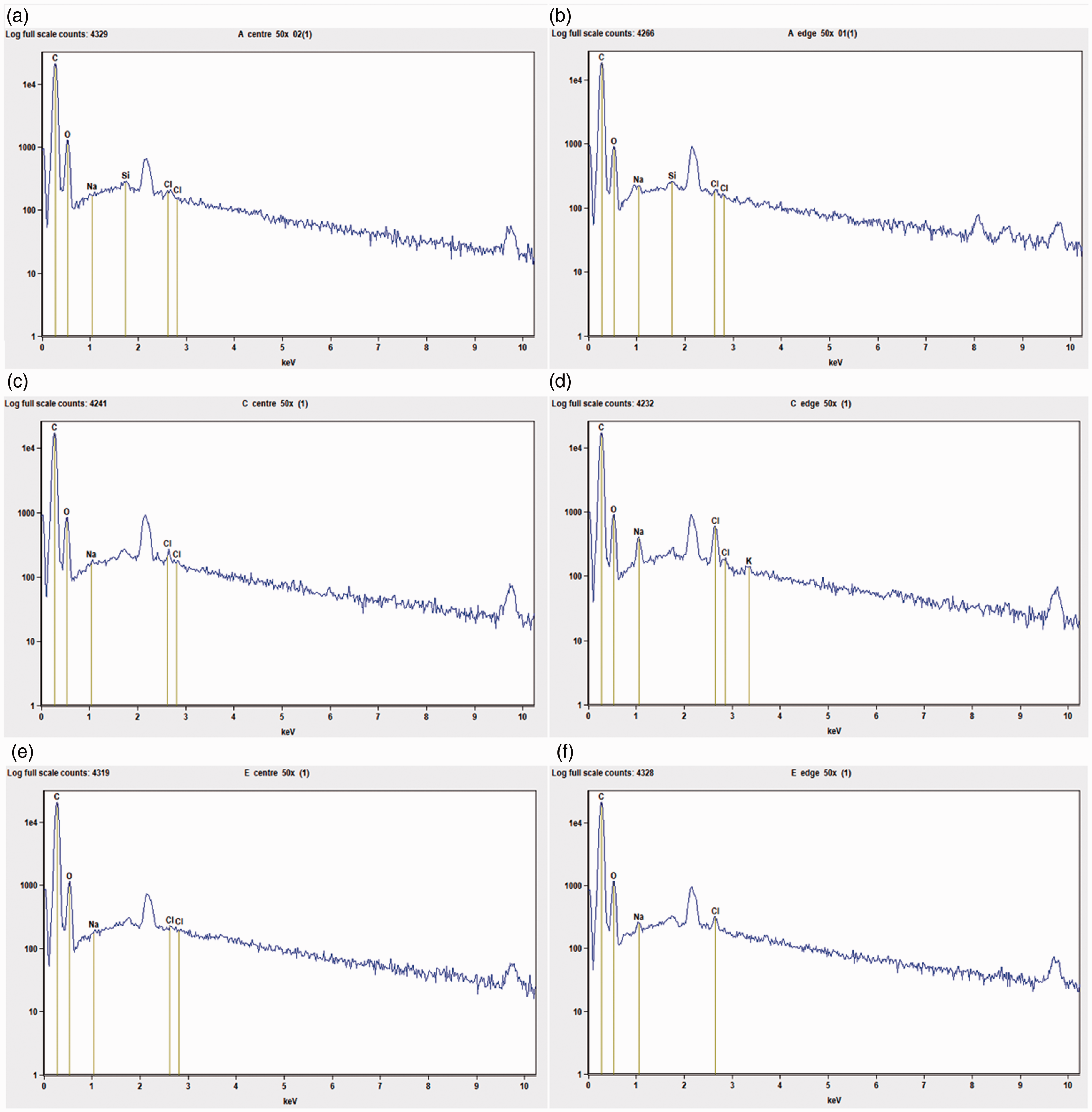
Conclusion
Composite peel tests were carried out to evaluate the interlaminar adhesion of a composite laminate under salt water environment. A carbon-epoxy laminate was chosen for analysis. Specimens were aged in a salt water tank for 60 days and then dried for 280 days. Tests were performed in non-aged and aged specimens, and after ageing and drying. The following conclusions were obtained from the analysis of test results and micrograph inspection of the fracture surfaces:
– The ageing process resulted in a relatively high weight increase due to the hand lay-up manufacturing process. – The average interlaminar peel strength decreased with the ageing process. – Fractographic analysis using SEM shows a typical mode I fracture behaviour. A mixture of matrix failure and fibre/matrix interface failure is present in non-aged specimens. The ageing process degraded the fibre/matrix interface adhesion turning it into the dominant failure mechanism. – The damage on the adhesion of fibre/matrix interface caused by salt water ageing was unrecoverable after drying. The interlaminar peel strength remained low and the dominant fracture surfaces remained in the fibre/matrix interface. – EDS analysis confirmed the penetration of water near the edges of the fracture surfaces. The presence of salt is noticed in these areas. There was a decrease on the salt content at the edge of the specimen after drying. However, it had no effect in the test results nor significantly changed the fracture surface. – Floating roller peel tests proved to be an easy and reliable method to access the interlaminar adhesion quality of composite laminates.
Footnotes
Declaration of conflicting interests
The author(s) declared no potential conflicts of interest with respect to the research, authorship, and/or publication of this article.
Funding
The author(s) disclosed receipt of the following financial support for the research, authorship, and/or publication of this article: This work was supported by the Brazilian Research Agencies: Conselho Nacional de Desenvolvimento Científico e Tecnológico (CNPq); Coordenação de Aperfeiçoamento de Pessoal de Nível Superior (CAPES); Fundação Carlos Chagas Filho de Amparo à Pesquisa do Estado do Rio de Janeiro (FAPERJ); and the Netherlands Organisation for Scientific Research (project number 14366).