
Abstract
This work introduces a new approach for the dynamic simulation of a permanent magnet-assisted synchronous reluctance machine with the ability to consider dynamic changes in the rotor magnetization. The aim is to comprehensively analyze the dynamics of a machine through transient simulations of the occurring magnetic and mechanical forces that influence the noise and vibration characteristics. A simplified magnetic model considering the effects of magnetic reluctances, leakage flux, and magnetic saturation is utilized to efficiently calculate the dynamically changing magnetic forces in the air gap. Unlike conventional designs employing rare earth magnets in the rotor, the design at hand utilizes non-rare earth magnets that enable adjustments of the magnets’ flux output. The novelty of the presented approach lies in its ability to consider these dynamic changes when calculating the air gap flux. The magnetic forces are then applied to an elastic multibody model of the motor, which includes the rotor, stator, bearings, and the housing, for the computation of the bearing forces and housing deformations. The presented multi-physical model allows for transient simulations of the forces acting on the bearings and the housing, capturing the dynamic response of the motor under varying rotor magnetization, air gaps, and loads. With the proposed approach, this study offers predictions regarding critical vibration characteristics that occur during dynamic operation, providing valuable insights for noise reduction efforts.
Keywords
Introduction
Various electric machines have emerged as key components driving the advancement of modern mobility concepts. Most prominently, permanent-magnet synchronous motors (PMSMs) relying on rare earth magnets are used due to their remarkable power densities and high torque production. However, the mining of rare earth magnets comes with significant ecological detriments and their scarcity often leads to cost and availability issues. In contrast, synchronous reluctance machines (SynRMs) do not require rare earth magnets, as they generate torque through magnetic reluctance. The reluctance force arises from a special rotor geometry that enables the passage of magnetic flux in one direction while hindering its flow in another direction through the presence of flux barriers. Due to their straightforward rotor design, SynRMs are very efficient and capable of high speeds while providing low manufacturing and maintenance costs. However, the absence of rotor magnets in the SynRM leads to reduced power densities and power factors compared to conventional PMSM. To address these limitations, permanent magnet-assisted SynRMs were introduced. 1 For this machine topology, non-rare earth permanent magnets are embedded within the flux barriers of the rotor, thereby enhancing torque production. This hybrid machine topology can mitigate the downsides of the pure PMSM or the pure SynRM. 2 Commonly, non-rare earth permanent magnets exhibit lower remanent flux densities and lower coercive forces compared to their rare-earth magnet counterparts. However, this apparent drawback can be used favorably. The low coercive force facilitates the change of the magnets’ flux output during operation and thus provides an additional degree of freedom (DOF) for controlling the machine’s torque output. 3 This kind of motor is also referred to as variable flux SynRM.
The wide operating speed range of SynRMs renders them especially susceptible to undesired vibrations that may arise from magnetic or mechanical disturbances. While electromagnetic vibration and noise are mainly caused by higher space and time harmonics in the air gap flux, magnetic saturation, and slot openings, mechanical vibration can mostly be associated with the bearings, shaft misalignment, and rotor eccentricities. 4 For electric machines, the prevailing approach is to calculate the magnetic flux by the finite element method (FEM) for a steady-state scenario, and subsequently applying these forces to a finite element (FE) model of the stator.5–8 In most of these approaches, the vibration and noise analysis is done in the frequency domain. Other methods generate look-up tables from FE data for subsequent transient simulations.9,10 While FEM is well-suited for precise calculation of the magnetic flux, its computational cost remains high, sometimes even prohibitively high.
Lumped parameter models such as equivalent magnetic circuits (EMCs) bridge the gap between analytical and FE models by utilizing equivalent circuit elements to calculate the magnetic flux. 11 In contrast to fundamental wave models, EMC facilitate the systematic incorporation of nonlinearities such as inhomogeneous air gaps and iron saturation. Models of significantly reduced complexity can already sufficiently well represent the motor behavior with respect to the forces, currents, and voltages, allowing for much faster computation times.12,13 Hence, utilizing appropriately selected EMC networks as the foundation for transient dynamical simulations of noise and vibration phenomena are promising.
Based on earlier works,14,15 in this article, a method for transient multi-physical modeling and simulation of a variable flux SynRM is introduced, with particular emphasis on accurate calculation of radial magnetic forces within the air gap. The mechanical motor model is given by an elastic multibody system (EMBS), thereby enabling the consideration of a variable air gap, elastic bearings, and rotor eccentricities. Leveraging this framework, the goal is to analyze the vibrations along the bearings and the stator and their impact on the housing under various transient scenarios. Furthermore, through the systematic and detailed incorporation of the rotor magnets in the EMC, the implications of a change in the flux output of the PMs during operation and the resulting forces are investigated.
When utilizing FEM for the simulation of the magnetic forces,5–10 it is computationally expensive to incorporate dynamic magnetic properties such as a changing rotor magnetization. Also, when utilizing look-up tables, they need to be recomputed for each new set of parameters. In contrast, the presented approach makes use of the EMC method for the magnetic quantities, which comes with the advantage of being able to systematically incorporate the flux output of the permanent magnets. Other work also makes use of the EMC method,13,12 but only for static analysis and without the consideration of dynamic changes in the rotor magnets. The presented model enables transient adjustments in the permanent magnets’ flux output while the electromagnetic forces can be simulated efficiently and with good quality. By incorporating this dynamic element, the model provides a more comprehensive understanding of the complex interactions between electromagnetic forces, mechanical vibrations of the motor housing, and resulting noise through efficient transient simulations.
Mechanical modeling
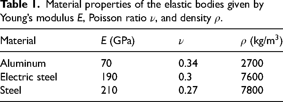
The fundamental mechanical components of the electric motor are given by the rotor, the stator, the bearings, and the housing. In order to analyze the dynamical excitations of the housing caused by the magnetic forces in the air gap or imbalances of the rotor, the mechanical parts of the motor are described within the framework of an EMBS. The deformation of the elastic bodies in EMBS is assumed to be small compared to their respective rigid body movements, allowing the separation of large nonlinear motions into a nonlinear rigid body motion and a linear elastic deformation with respect to a floating frame of reference.16,17 In combination with model order reduction (MOR) methods, EMBS simulations achieve much faster computation times than classical FE analyzes while still being sufficiently accurate. Here, the housing, bearings, and the stator are represented by elastic bodies, as these components predominantly contribute to the vibration characteristics of the motor. Further, the influence of the coils in the stator slots is neglected. For simplicity, the shaft and rotor are assumed to be rigid. The elastic bodies are modeled separately, which allows for the consideration of different material properties of the respective components. The stator is composed of electrical steel while the bearings are made of regular steel. In contrast, the housing is made of aluminum. Due to its lower density and stiffness, the aluminum housing is more susceptible to vibrations, which can lead to an increased level of noise. The material properties for the elastic bodies are given in Table 1. Subsequently, the parts are discretized into FE meshes using the commercially available software Abaqus 18 and appropriately joined using tie constraints. With this kinematic constraint, two separate surfaces are tied together such that there is no relative motion between the corresponding surface nodes. The elastic parts are shown in Figure 1. Due to the high computational complexity of FE models, a dimensionality reduction is indispensable for transient simulations.
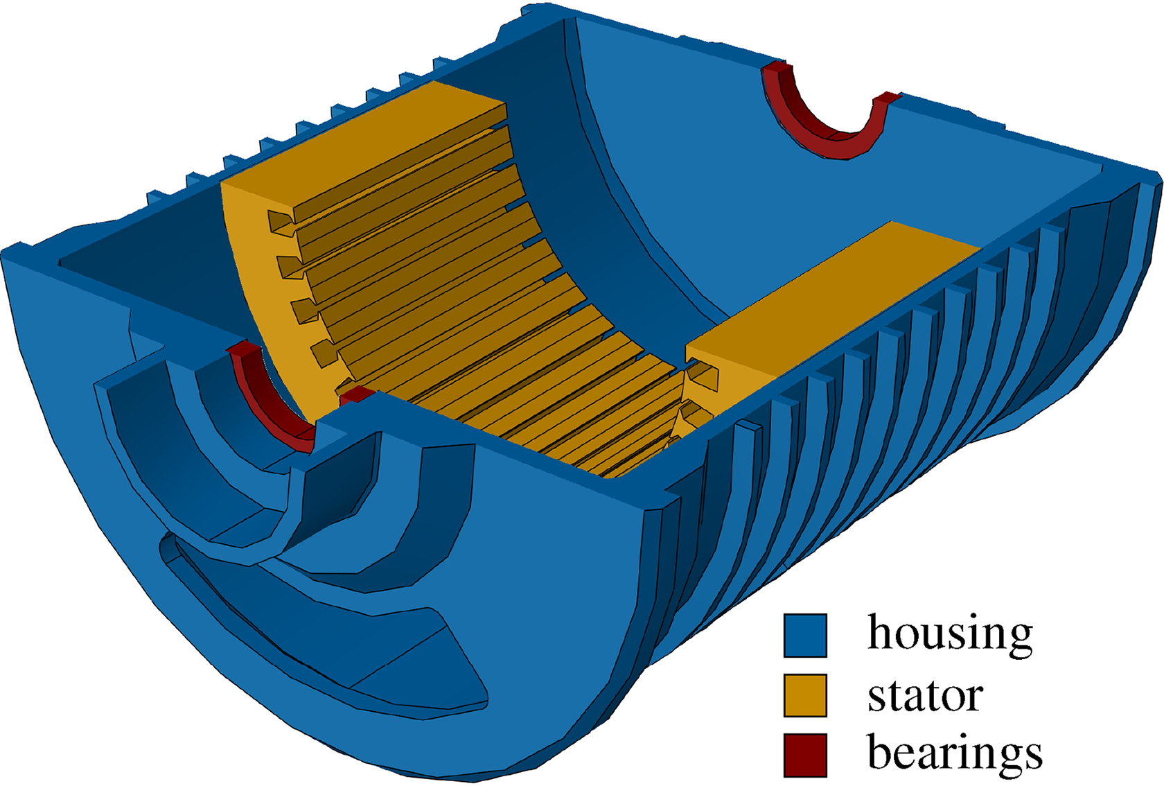
Sectional view of the elastic components.
Material properties of the elastic bodies given by Young’s modulus
Model order reduction
Each elastic body is described by a linear FE model with 


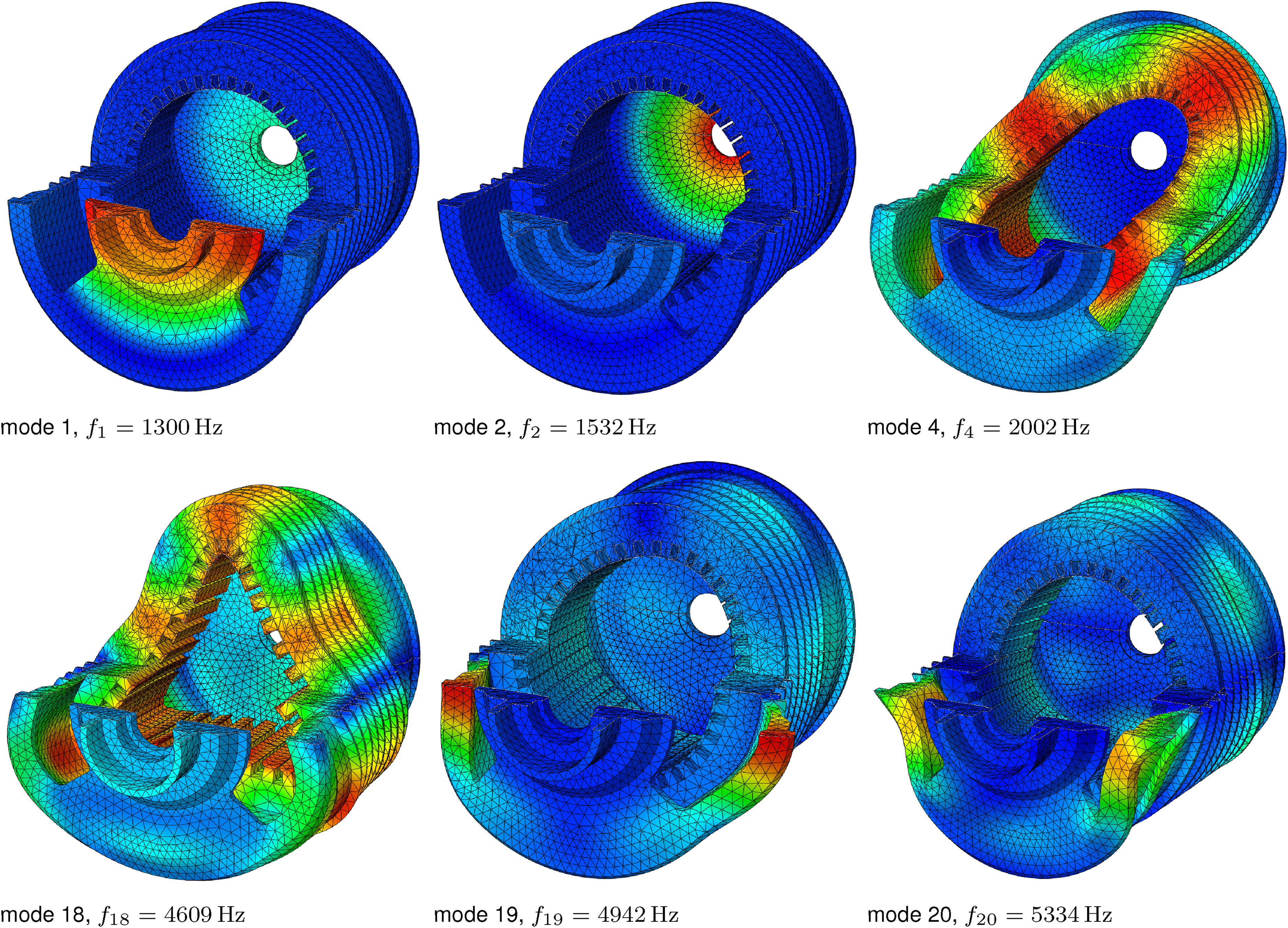
Selected mode shapes of the elastic body: mode 1,
Elastic multibody system
In this step, the rigid rotor together with the reduced elastic bodies from the “Model order reduction” section are assembled to form the EMBS. The rotor is modeled as a rigid body with mass 
Electromagnetic system
The electromagnetic model facilitates the computation of the magnetic flux within the motor, yielding both radial and tangential forces in the air gap. The radial forces are subsequently applied to the stator teeth, while the tangential forces are responsible for the torque generation. In order to enable transient simulations, the computational speed of the FEM for calculating air gap forces is insufficient. As a result of this limitation, the magnetic flux is modeled using an EMC that emerges from approximating the flux distribution through lumped elements such as reluctances and magnetomotive forces.
The motor investigated in this work is part of the research project “Effective reluctance machine for emission-free mobility without rare earths” funded by the Ministry of Science, Research, and Arts of the Federal State of Baden-Württemberg in the framework of “Innovationscampus Mobilität der Zukunft”. In the previous project phase, a new machine concept for increasing the efficiency of hybrid SynRMs has been developed. The new concept is based on solving the conflicting goals of pure SynRMs between optimal electromagnetic utilization of the rotor and mechanical load capacity by introducing a fiber-reinforced polymer material into the flux barriers and using magnets without rare earths. In this way, the efficiency can be improved, and the power density can be increased. By substituting air with fiber-reinforced polymers, the rotor gains increased strength and resistance to mechanical stresses, thereby ensuring reliable performance and minimizing the risk of structural deformations or failures during operation and thus allowing for higher maximum speeds.
22
For the second project phase, the design and manufacturing of the motor prototype is done. The considered motor is a three-phase
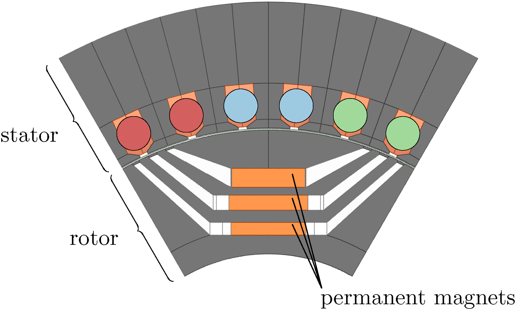
Sectional view of one motor pole including the rotor with its permanent magnets and the stator yoke, teeth and copper windings.
Due to the magnetic symmetry inherent to each rotor pole pair and when assuming a constant air gap, it is usually possible to consider only one pole for magnetic simulations. This effectively reduces the computational burden associated with the simulation. However, in the current investigation, the magnetic forces depend on the air gap width
Magnetic circuit
For the calculation of the magnetic flux, the stator, the rotor, and the air gap are approximated by areas of constant cross-section and modeled with appropriate reluctances. Figure 4 shows the EMC of one pole. Note, that compared to earlier work,
14
here the reluctance network has been extended to incorporate permanent magnets in the rotor, enabling the consideration of a varying rotor flux. The magnetomotive forces caused by the coils around the stator teeth are given by 
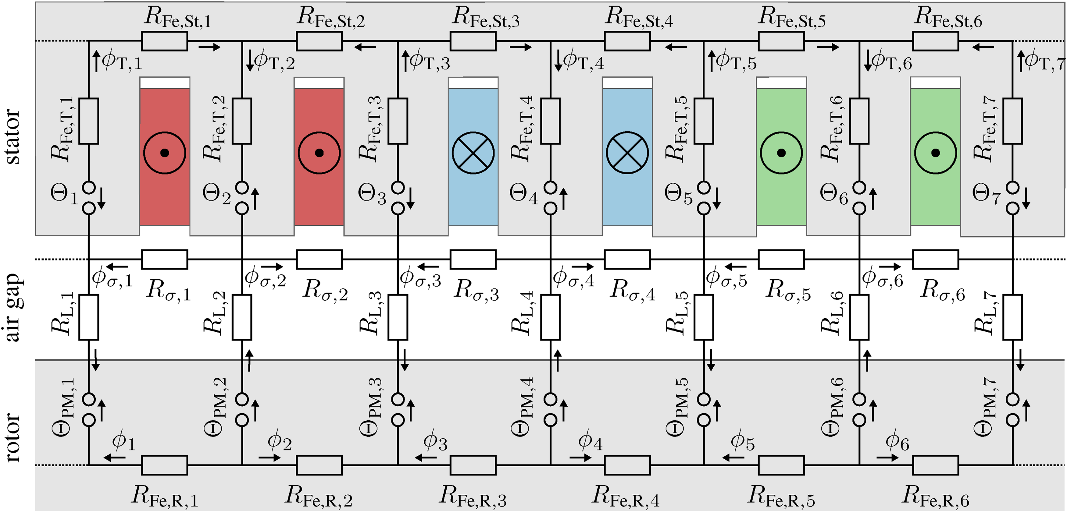
The magnetic equivalent circuit for one pole with the considered reluctances and magnetomotive forces.
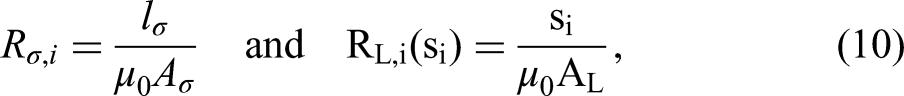
The reluctances within the given reluctance network can be classified into two distinct groups. First, the nonlinear reluctances of the iron components in the stator and rotor. Second, the linear reluctances in the air gap. The stator yoke reluctances 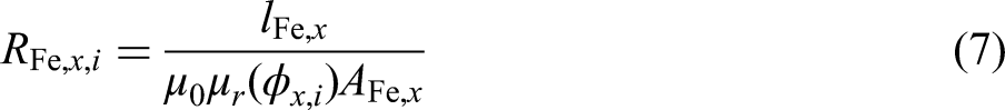

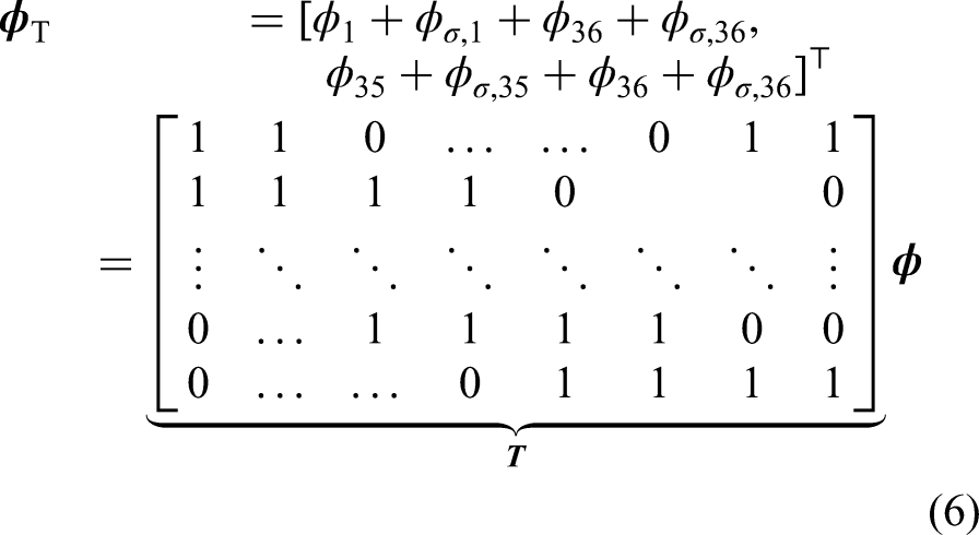
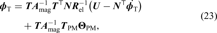
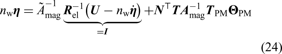
The equations for the magnetic network can now be formulated utilizing Kirchhoff’s second circuit law and Ohm’s law for magnetic circuits yielding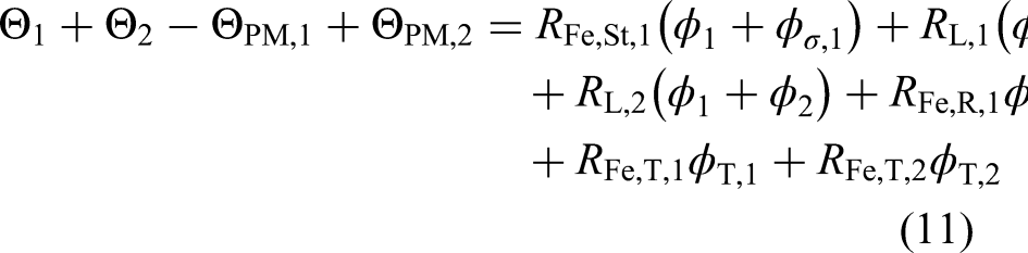
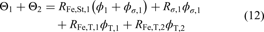

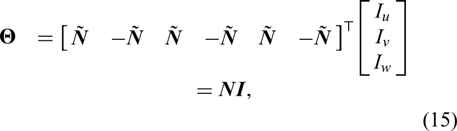
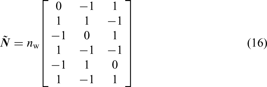
In contrast, the magnetomotive forces 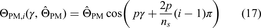

Next, the coupling between the electric circuit and the magnetic network is realized through Kirchhoff’s second circuit law and Faraday’s law of induction for the stator coils. The introduction of the phase voltages 

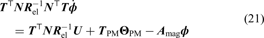


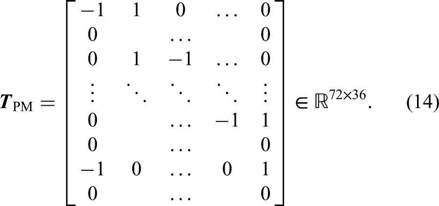
Note, that 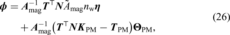
Magnetic forces
In a last step, the magnetic forces resulting from the air gap fluxes need to be calculated. As depicted in Figure 4, the radial forces perpendicular to the rotor surface can directly be attributed to the air gap fluxes 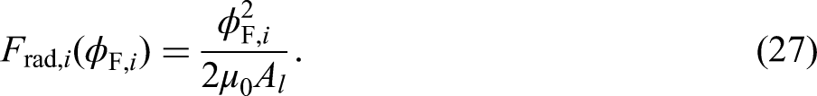

Dynamic equations for the complete magnetic system
In summary, the input–output description of the magnetic model is defined by the DAE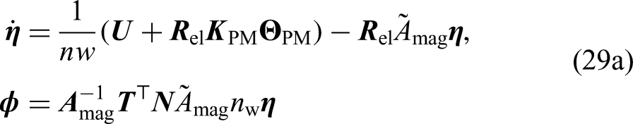


Parametrization
For the simulations in this contribution, the magnet model described in the “Magnetic circuit” section is parametrized according to the design presented in our previous work.
22
The characterizing parameters of the magnetic model are the lengths and cross sectional areas of the flux tubes represented by
The geometric parameters for the lumped network elements are chosen based on available computer-aided design data. Thereby, the flux paths through the stator yoke, the stator teeth, the air gap, and the rotor are approximated by the flux tubes illustrated in Figure 4. Further, the number of turns per stator coil
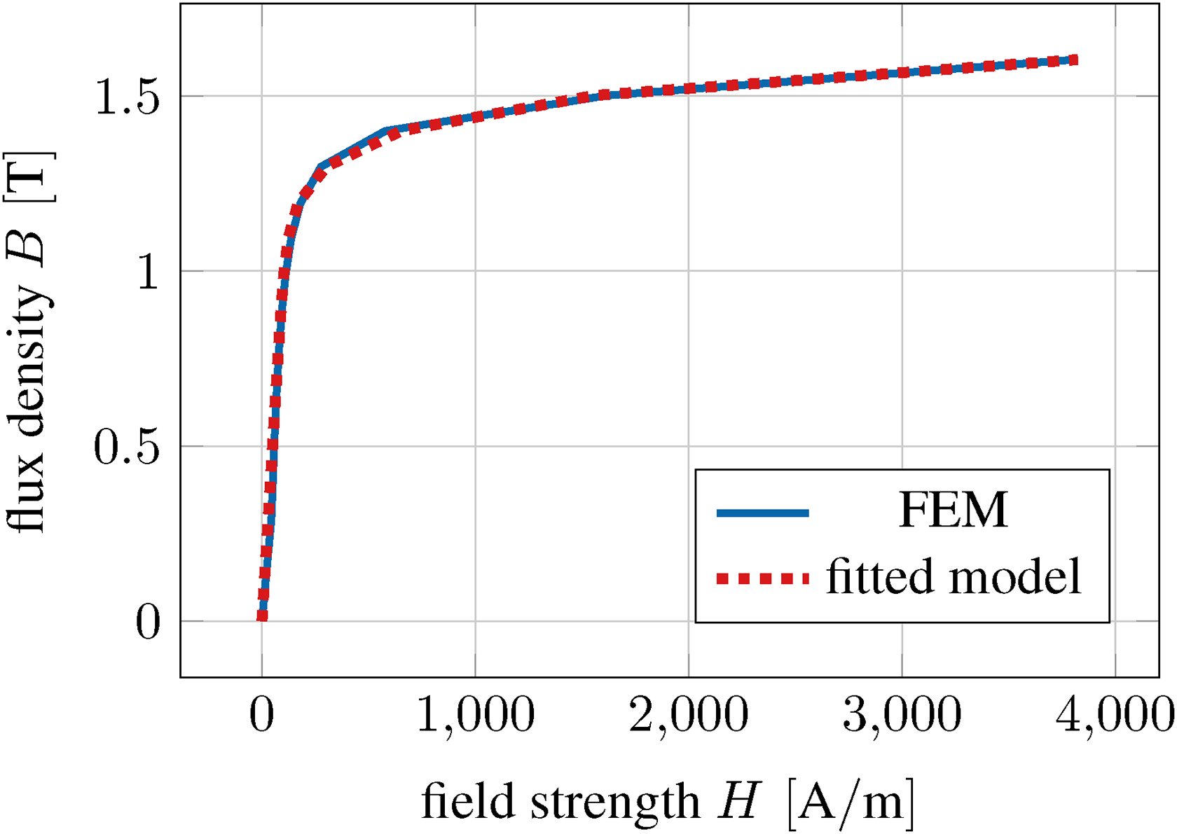
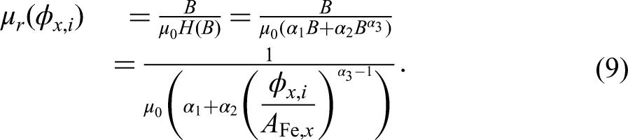
Analytical approximation of the magnetic field intensity and flux density (BH) curve for the nonlinear permeability
Dynamic simulation
The presented multi-physical model of the SynRM is now employed to conduct numerical exemplary simulations. For this, the elastic bodies of the housing, stator, and bearings are discretized resulting in a total of
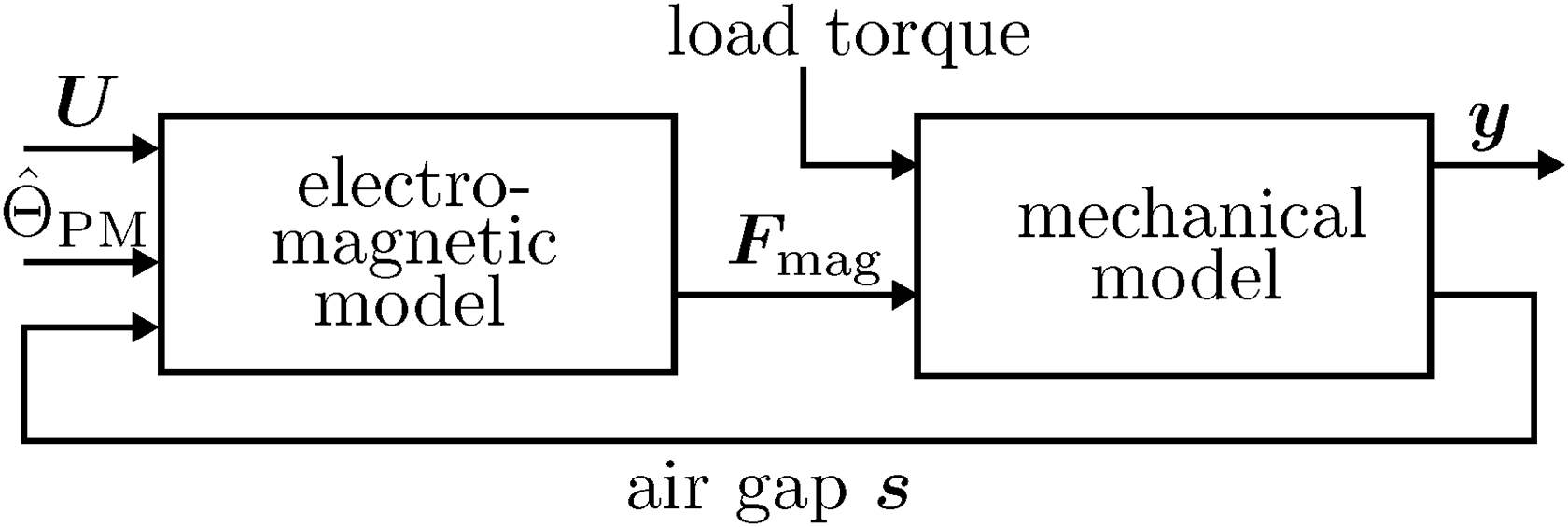
Overall structure of the machine model with the three-phase input voltages
In the first simulation, the dynamical system behavior is analyzed during a run-up of the machine with no load. The machine is supplied with a three-phase input voltage with a peak of 100 V yielding an increasing rotational velocity. In this case, the magnetomotive forces of the permanent magnets in the rotor are kept constant. Subsequently, the resulting bearing forces and vibration of the surface nodes of the housing are investigated. In the second simulation, the change in magnetization of the rotor magnets is considered. In this scenario, magnetization of the rotor magnets is changed during the simulation and the occurring forces and housing vibrations are analyzed.
Run-up
The machine is run up to a maximum rotational velocity of 10,000
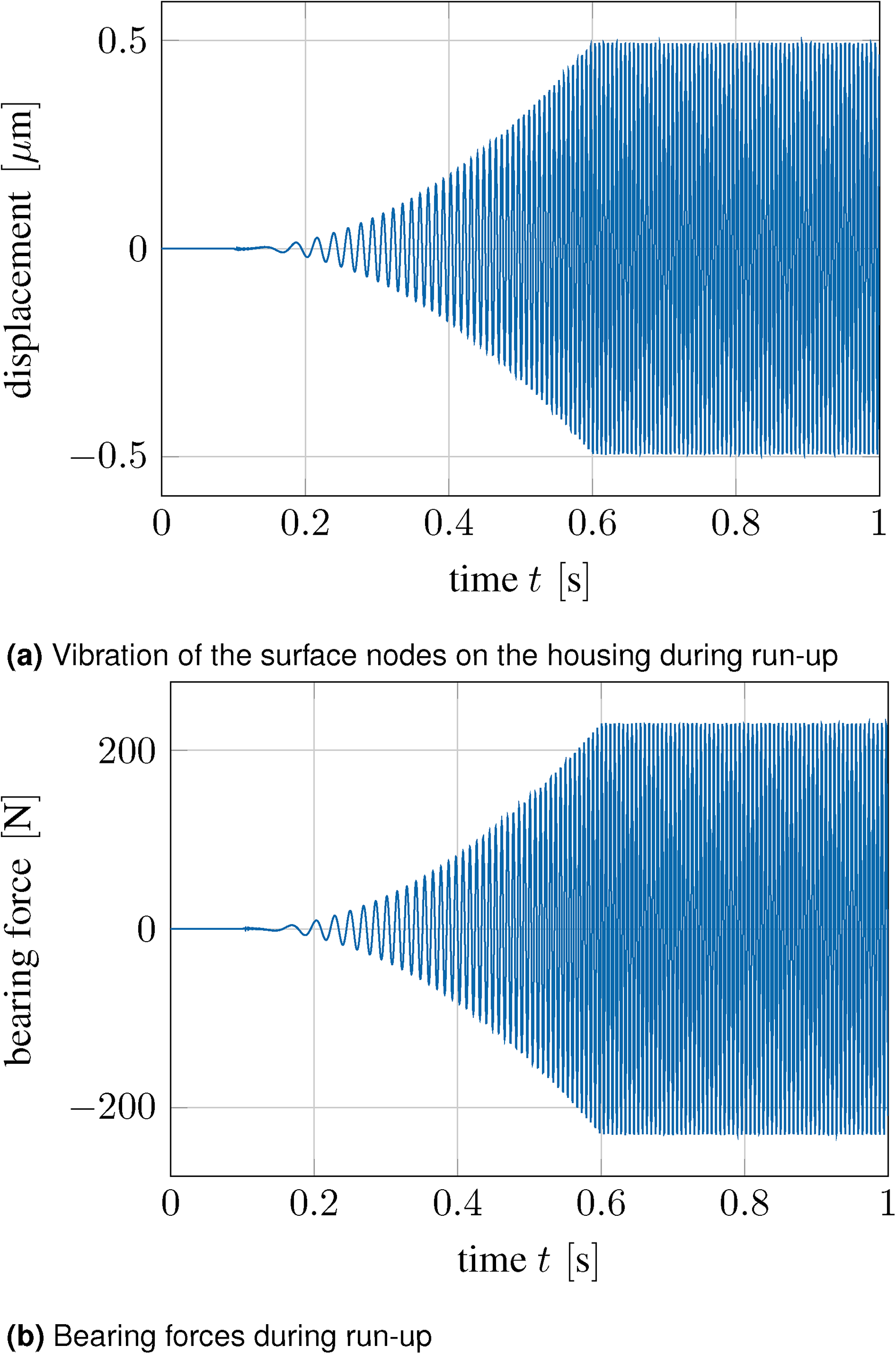
Vibrations and forces during run-up from 0 to 10.000
Change in magnetization
Now, the rotational velocity of the rotor is set to be constant at 10,000
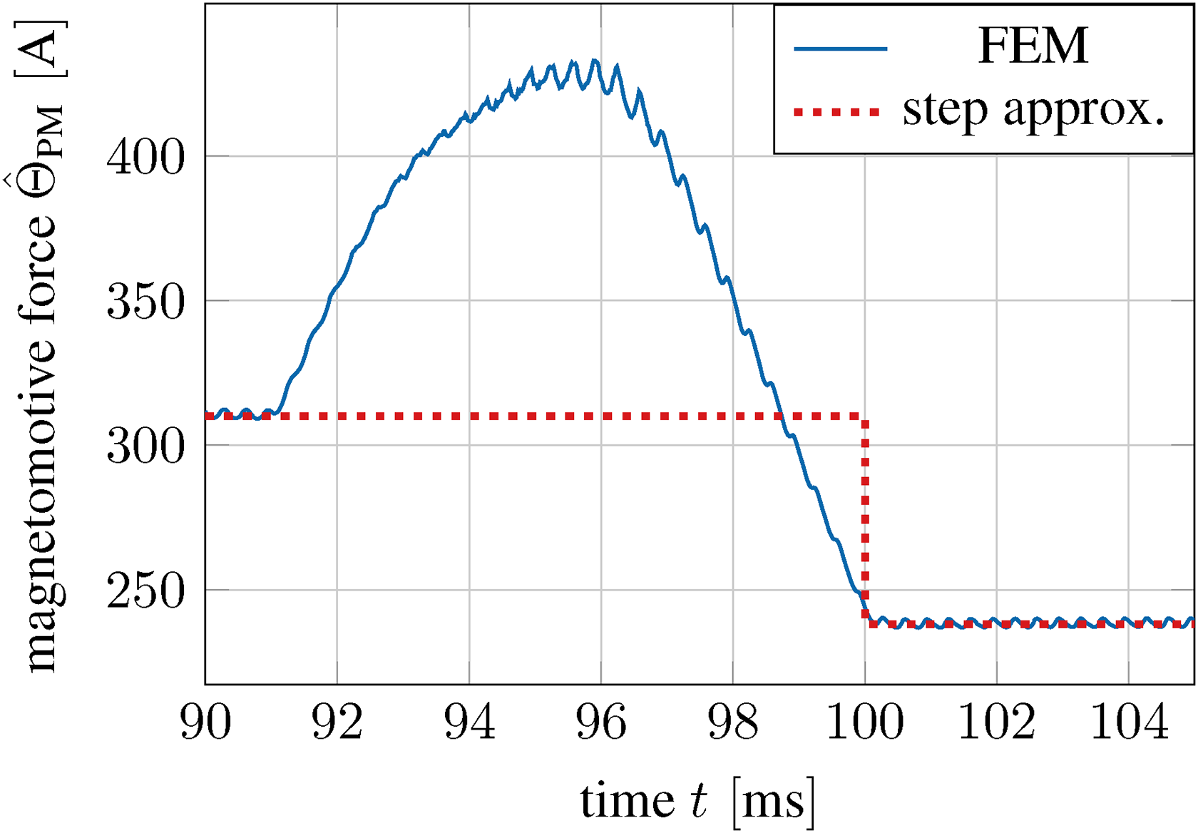
Approximation of the change in magnetization of the permanent magnets through a step at
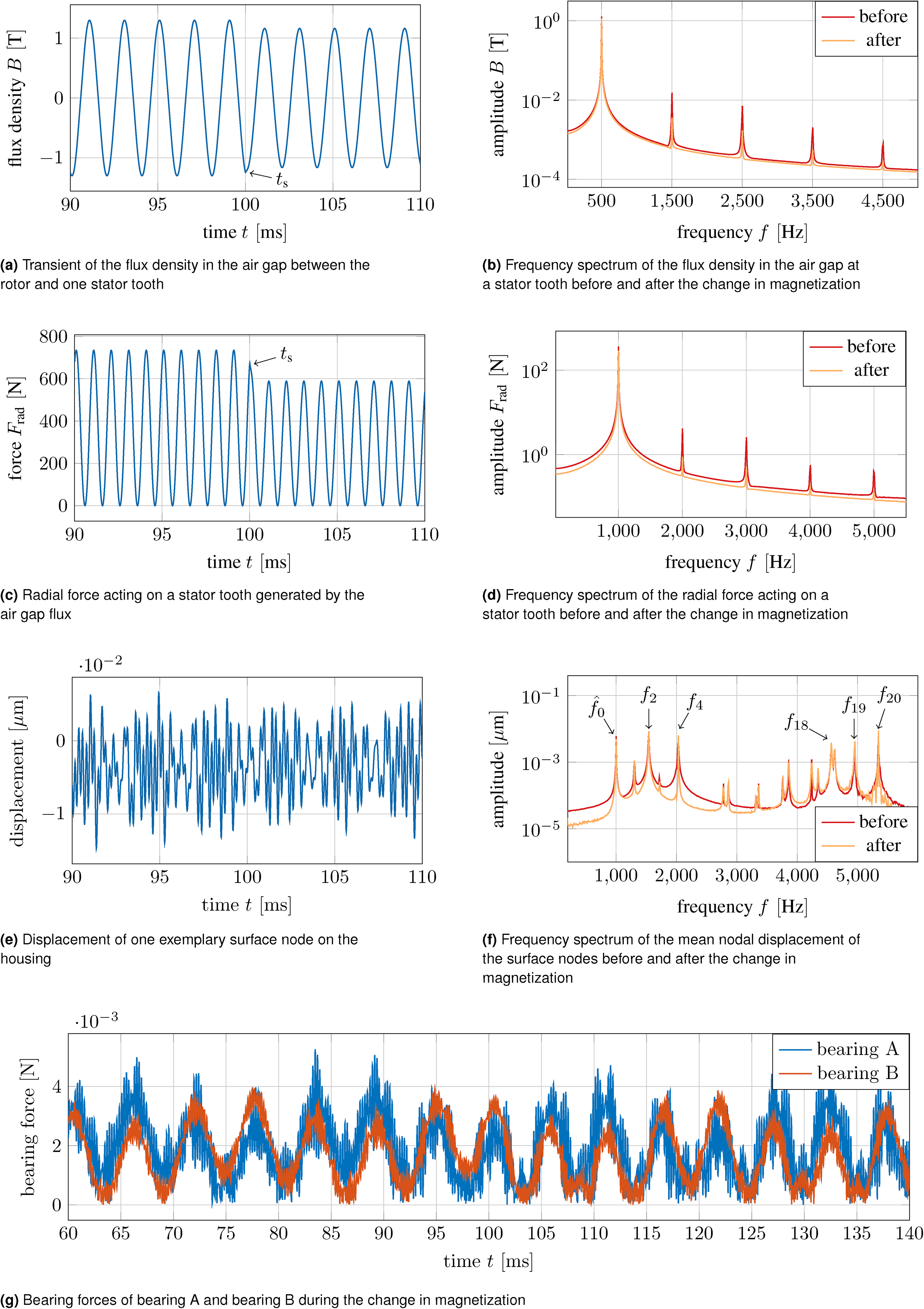
Transient behavior of characteristic quantities before and after the change in magnetization at

Frequency spectrum of the housing surface nodes for magnetization values of ),  ) and
) and  ): (a) spectrum at 10,000
Conclusion and outlook
A dynamic model of a variable flux reluctance machine has been introduced, covering the mechanical and electromagnetic properties of the machine. The utilization of an EMC model allows for the consideration of effects such as iron saturation and leakage flux, while being much more computationally efficient than FEMs. The outputs of the magnetic model are the radial and tangential forces in the air gap. These are the main source of vibration in such machines. They are also the input for the mechanical model, which is realized as an EMBS. To ensure fast computation speeds, the dimensionality of the elastic parts is reduced using MOR techniques. The ability to consider time-varying rotor magnetizations constitutes the novel contribution of this study. It facilitates transient simulations of the interaction between the housing and the magnetic forces contributing to the noise and vibration for time-varying rotor magnetizations by considering the most important magnetic and mechanical quantities.
In this study, two different scenarios were analyzed. During the run-up phase, the machine was subjected to increasing rotational velocities. The presence of a static rotor eccentricity added imbalance to the rotation, resulting in high forces on the bearings and stator. The simulation enabled the investigation of bearing forces and housing vibrations, providing information about the machine’s strain at high speeds. In the second scenario, the change in magnetization of the rotor magnets was simulated. Further, the vibrational behavior of the housing was analyzed for different magnetizations of the permanent magnets. The results show that the change in magnetic flux output of the permanent magnet can change the machine’s vibrational behavior significantly. This strongly depends on the actual flux output of the permanent magnets. For the considered change in magnetization, the effects on the bearings and the vibration of the housing are limited. However, if the flux output is further increased, the vibrational behavior is altered by introducing higher order harmonics in the air gap flux. This may be the case for alternate working points of the machine. However, the calculation of optimal magnetizations depending on the working point is beyond the scope of this study.
Overall, the dynamic simulation provided a deeper understanding of the variable flux SynRM’s behavior under varying conditions. This multi-physical approach facilitates the transient simulation and analysis of the most important magnetic and mechanical quantities. The insights gained from this study can contribute to the design and improvement of SynRMs, ultimately enhancing their efficiency and vibrational behavior by providing an accurate and fast simulation framework. Among the next steps is the investigation of vibrations of the housing and their influence on the noise radiation. Since the electromagnetic forces can now be simulated efficiently and with good quality, the noise radiation is a problem which can nicely be tackled without additional physical effects by the derived flexible multibody model.
Footnotes
Acknowledgments
The authors would like to express their gratitude to Florian Bechler for his preceding work and his assistance during the development of the magnet model. All authors would like to thank the Ministry of Science, Research, and Arts of the Federal State of Baden-Württemberg for the financial support of the project “Effiziente Reluktanzmaschine für emissionsfreie Mobilität ohne seltene Erden 2” within the “InnovationsCampus Mobilität der Zukunft.”
Declaration of conflicting interests
The author(s) declared no potential conflicts of interest with respect to the research, authorship, and/or publication of this article.
Funding
The author(s) disclosed receipt of the following financial support for the research, authorship, and/or publication of this article: This work was funded by the Ministry of Science, Research, and Arts of the Federal State of Baden-Württemberg in the framework of “Innovationscampus Mobilität der Zukunft”.