
Abstract
To address vehicle drivetrain vibrations that cause discomfort and poor drivability, this study proposes a new active damping strategy with simple backlash compensation based on the simultaneous perturbation stochastic approximation (SPSA) with norm-limited update vector. First, an experimental device developed for a simplified drivetrain mechanism is demonstrated. A mechanism for reproducing both the contact mode and the backlash mode is included in the device. For the contact mode, a model-based
Keywords
Introduction
Vibrations cause noise, fatigue failure, and discomfort, providing an adverse influence for mechanical systems. The need for vibration suppression technology has grown as a result of the current movement toward downsizing, greater comfort, weight reduction, and superior performance.1–3 Due to their potential to deliver strong dampening effects for intricate mechanical systems, active vibration damping has received a lot of research attention.
Vehicle drivetrains also require vibration control as one of the essential important technologies to maintain their functions. Vibrations induced by a sudden driving force change in the drivetrain 4 of a vehicle persist as a serious problem. These vibrations not only degrade the comfort and drivability but also reduce the durability of the drivetrain components. As one of the promising countermeasures, coupling a nonlinear dynamic vibration absorber in parallel to a drivetrain mechanism can be considered. For example, a nonlinear energy sink (NES)5,6 can efficiently dissipate vibrational energy through structural damping by redistributing the vibration energy within the modal space of the primary structure or passively absorb a part of this energy from the drivetrain in a nearly irreversible form. The advantage is that it can operate over a broad range of frequencies. In the successful application to attenuation of drivetrain vibrations, 5 three types of NESs were investigated: a third-order NES stiffness, a vibro-impact nonsmooth NES and a NES with fifth-order smooth nonlinear stiffness.
The use of NESs is categorized as passive vibration control, whereas this study focuses on developing the active vibration control method for drivetrain vibrations. NES is a lightweight absorber effective over a broad range of frequencies; however, active vibration control is also needed in order to obtain higher vibration suppression performances without increasing the weight of the driveline at all. Compared to passive control such as NESs, active control can provide stronger damping effects based on control algorithms by using only an existing actuator and do not need to incorporate additional palliative devices, thus reducing the associated costs. For the active vibration control of the vehicle drivetrain, some advanced control strategies have been presented, such as compensation for a disturbance based on an adaptive observer 7 for damping control of internal combustion engine powered powertrains. Further, an adaptive active control scheme has been developed by combining model prediction and Butterworth filter control to solve the torsional vibration problem. 8 In addition, the filtered-x least mean square algorithm 9 and a model reference controller have been implemented. 10 Moreover, a previous work has improved vehicle drivability by using a linear quadratic tracking controller with a model reference adaptive technique. 11
However, the aforementioned studies have not considered the nonlinear backlash existing in the gears of drivetrains. Backlash in a drivetrain leads to an undesirable phenomenon, which significantly increases the vibration amplitude.12,13 The drivetrain dynamics switch between two conditions: “contact mode,” during which mechanical contact occurs, and “backlash mode.” Backlash mode disconnects the output side (wheel side) from the input side (actuator side) owing to the traversal in backlash. This phenomenon, that is, switching of the dynamics modes, also leads to higher complexity of control system structures and increases the designer's burden in terms of tuning tasks.
For a drivetrain with backlash, a hybrid strategy of a feedforward-feedback controller and a robust disturbance observer has been introduced to compensate for the backlash. 14 Sliding mode control-based approaches have also been investigated for a drivetrain with nonlinearity.15,16 Another study has adopted a combination of linear quadratic regulator (LQR) and a notch filter for the contact mode while dealing with the backlash mode using a proportional integral differential (PID) controller. 17
However, in the existing studies, the following shortcomings and rooms for improvement remain as:
With respect to controller parameters that must be determined by designers, there has been no attempt to adopt efficient optimization for auto-tuning of the parameters. The mechanism of compensation for backlash can be improved by making it simpler with a lower online computational load. Moreover, versatility is desired to facilitate its use with a wide variety of model-based linear controllers for satisfactory vibration reduction in the contact mode.
The optimization design is closely related to the complicated powertrain dynamics.18,19 Some researchers have employed efficient optimization algorithms for their applications, such as a gear shifting fuzzy controller and an engine management approach optimized using an advanced genetic algorithm (GA) with interactive adaptive-weight,20,21 multi-objective optimization,
18
lookup-table-based torque control,
22
and design of a torsional vibration damper (a dual mass flywheel with an internal damper).
23
The aforementioned works suggest the following important aspects: (1) effectiveness of iterative offline simulations based on powertrain dynamics models; (2) necessity of application of efficient optimization algorithms (rather than the designer's subjective selection) to automatically search for the controller parameters.
19
Focusing on active vibration controls of a drivetrain, their controller design can be framed as optimization problems. For the backlash mode, a previous study has developed a new clunk controller with model-based torque shaping. 12 It consists of a soft-landing reference governor and a proportional-derivative (PD) baseline controller to track the modified reference. The ingenious point is that the competing design requirements, that is, reducing the clunk when the backlash traversal finishes and allowing the backlash to be crossed rapidly, are defined as an optimal control problem. However, a contact mode controller12,24 and the aforementioned PD gains have not been included in auto-tuning optimization, although they are critical for addressing transient oscillations in a drivetrain. In addition, the optimization solution can be obtained more conveniently by introducing an efficient optimization algorithm. For the minimization of an objective function based on the root mean square (RMS) of drivetrain vibration responses, the LQR controller has been optimized offline. 25 The selection of the critical weighting matrices has been optimized with the GA. However, this work does not consider the backlash nonlinearity in a drivetrain. Another study has proposed a safe calibration framework based on Bayesian optimization to obtain the optimal controller gain. 26 However, the backlash has not been explicitly addressed in the controller. Among previous approaches, the most popular choice for powertrain dynamics control is model predictive control (MPC). 27 To address undesired oscillations due to backlash, the online MPC, which is a quadratic form-defined optimal control in a receding horizon, has been implemented. 28 In the literatures,29,30 switching strategies for multiple predictive controllers have addressed the nonlinearity in a powertrain. The MPC controller can produce ideal responses including little error states such as excessive jerks and transient oscillations. 31 Although MPC has achieved promising results, one of its main drawbacks is its high computational burden online. This makes it difficult to implement MPC on real-time applications without sacrificing the control performance. 12 Furthermore, the need to implement many different controllers makes the control structure more complicated, involving high requirements for the control module memory.
In summary, previous studies have not applied an optimization process for the contact mode controller or the backlash mode controller, that is, auto-tuning of the controller parameters is insufficient. In addition, few studies have focused on developing a simple and versatile backlash compensation strategy with lower online computational loads. Therefore, the novelty and principal contributions of our work are to bridge these gaps.
Based on our previous works,13,32 this study proposes an improved version of active drivetrain vibration control with compensation for backlash. In this article, the active controller is verified using an actual test device of a simplified drivetrain mechanism with backlash. We employ the reduced drivetrain configuration similar to the existing work
5
: this is a reduced lumped parameter model composed of a few inertias connected via stiffness. The model in the work
5
incorporates all the nonlinearities in the equation of motion such as the nonlinear stiffness of NESs, the aerodynamic drag torque and the tire rolling resistance, whereas this study only considers the dead zone property due to the backlash nonlinearity. This is because we need to focus on the effect of backlash and make it easier to evaluate the efficacy of the proposed backlash compensation. For considering the backlash and contact modes, the proposed control system is constructed as a simple compensation algorithm based on switching of the control modes, which can be applicable for a single model-based vibration controller. It can reduce the shock when a drivetrain is changed from the backlash mode to the contact mode while allowing the backlash to be traversed rapidly. Even though its versatility has been proven through some application examples with various model-based linear controllers,13,32 its critical controller parameters require manual setting based on trial-and-error tuning by the designer.
32
In other words, an auto-tuning design based on an optimization algorithm needs to be newly introduced. The contributions of this article can be summarized as follows.
As a novelty of this study compared to previous studies, both the backlash mode controller (i.e. a soft-landing compensator) and the contact mode controller (i.e. a baseline As a tuning algorithm, the simultaneous perturbation stochastic approximation with a norm-limited update vector (hereafter referred to as “NLSPSA” in this article) is employed. This work is the first to propose the application of NLSPSA for active damping of a drivetrain. This enables a high calculation efficiency while guaranteeing the stability of the iterative tuning process. To realize compensation for backlash, a simpler algorithm based on switching of the control modes is combined with a single output feedback Compared to a previous study that has only performed simulation tests,
33
this study experimentally confirms the effectiveness of the proposed method using an actual test device of a simplified drivetrain mechanism with backlash.
Basic experimental device
Simplified drivetrain with backlash
As the controlled object, this study considers a basic experimental device. By simplifying the actual driveline mechanism, this allows us to concentrate on the oscillation phenomena brought on by backlash effects and an abrupt shift in driving force. The device specifications are summarized in Table 1. The mechanical model and the actual test rig are given in Figure 1(a) and (b), respectively. The structure is a three-degree-of-freedom translational vibration system that is equivalent to a simplified drivetrain.13,34 The three mass points (
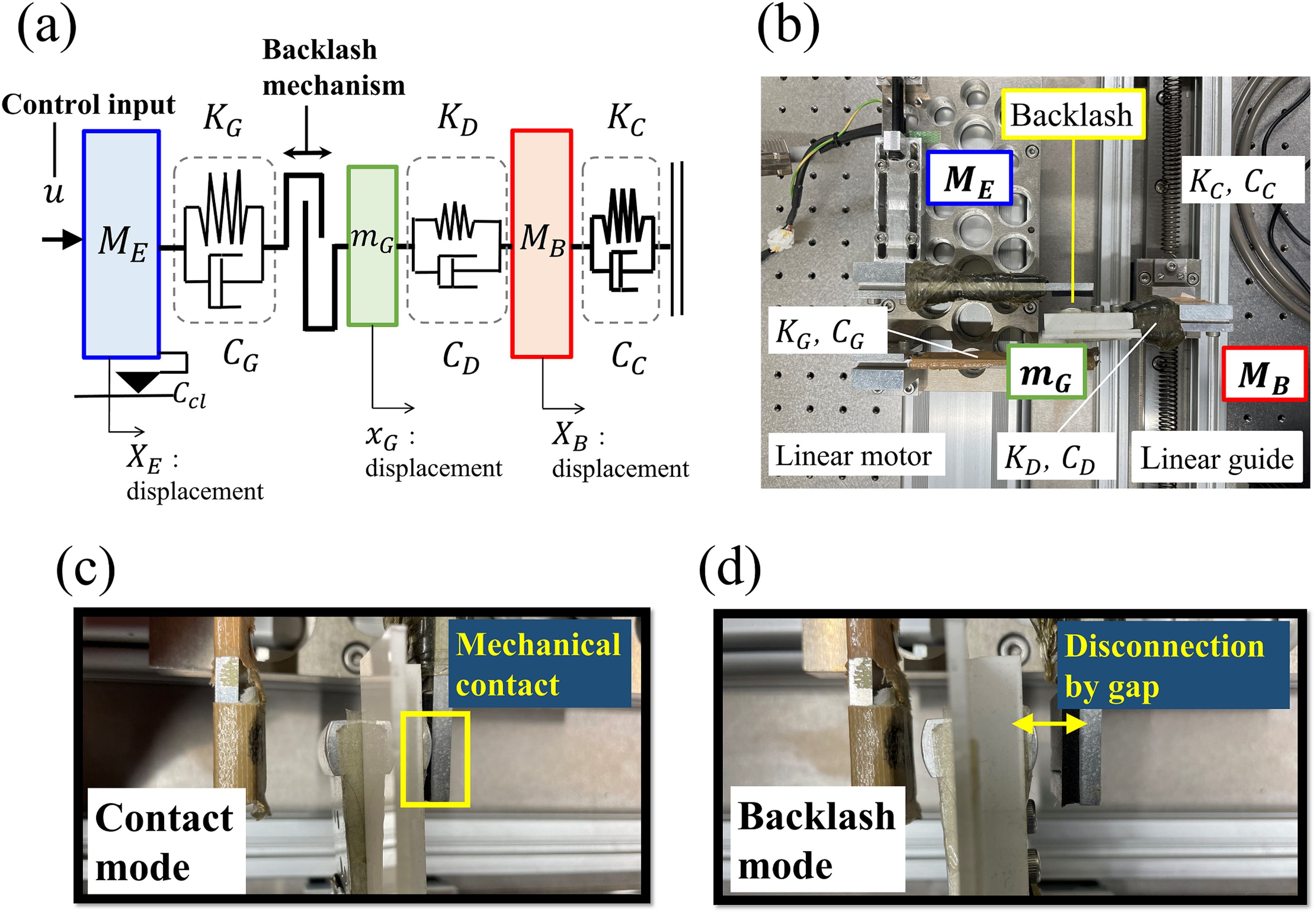
Basic experimental device: (a) drivetrain model; (b) real test device; (c) contact mode; and (d) backlash mode.
Specifications of the test device.
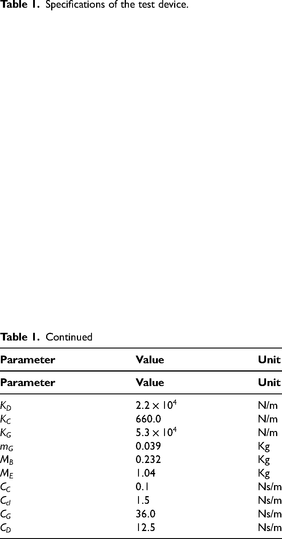
Figure 1(c) and (d) show the contact mode and the backlash mode, respectively. In the contact mode, the mechanical connection is established between the actuator and the vehicle body side. By contrast, the backlash mode is a disconnected situation during the backlash traversal.
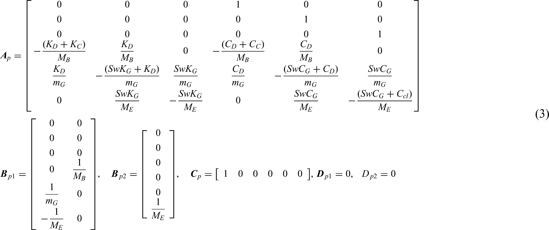
State-space representation for modeling
For the purpose of deriving a baseline vibration controller used in the contact mode, we need a linearized plant model because the experimental device involves nonlinearities such as backlash. As indicated below, the previous works have already derived the linear state-space representation of the plant dynamics in the form of the time-varying state equation.13,35


Active vibration control with compensation for backlash
The entire control structure consists of two main parts: the contact mode control (baseline vibration suppression) and the backlash mode control (simple mode-switching-based compensation). The control structure is shown in Figure 2.
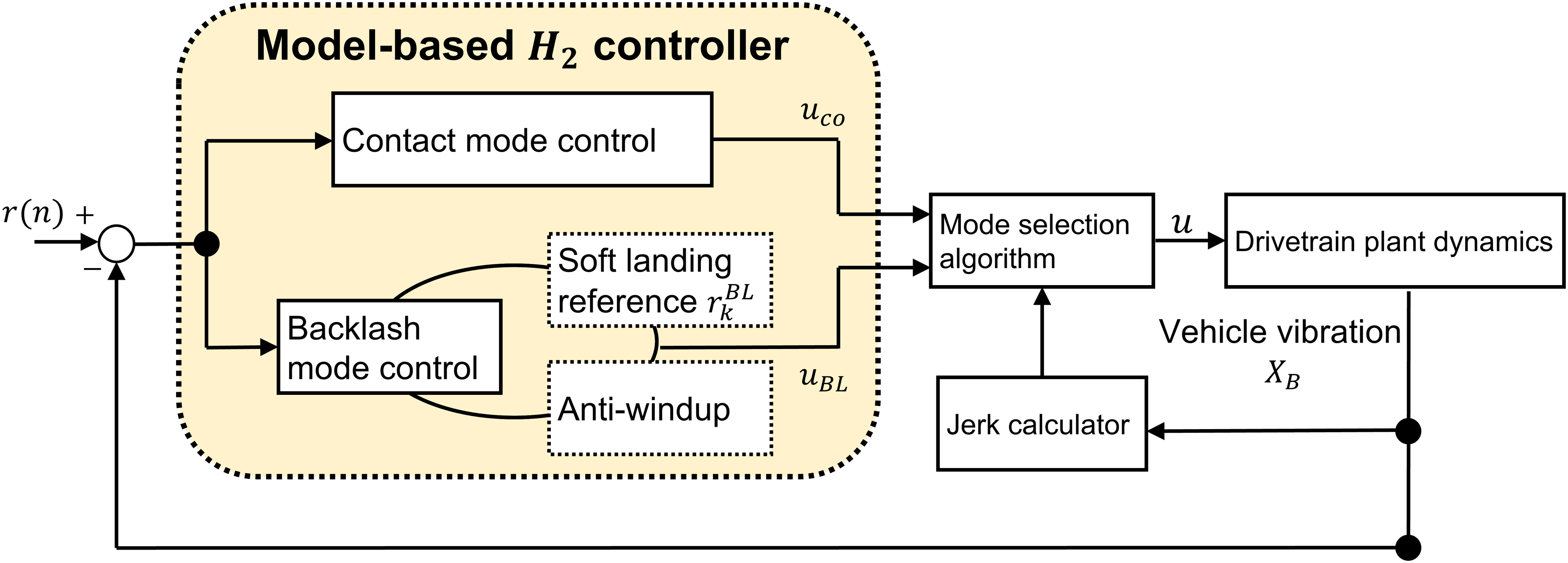
Active damping strategy composed of backlash and contact mode controls.
Model-based
vibration controller
As the baseline controller, a model-based linear
Figure 3 shows the block diagram used to design the
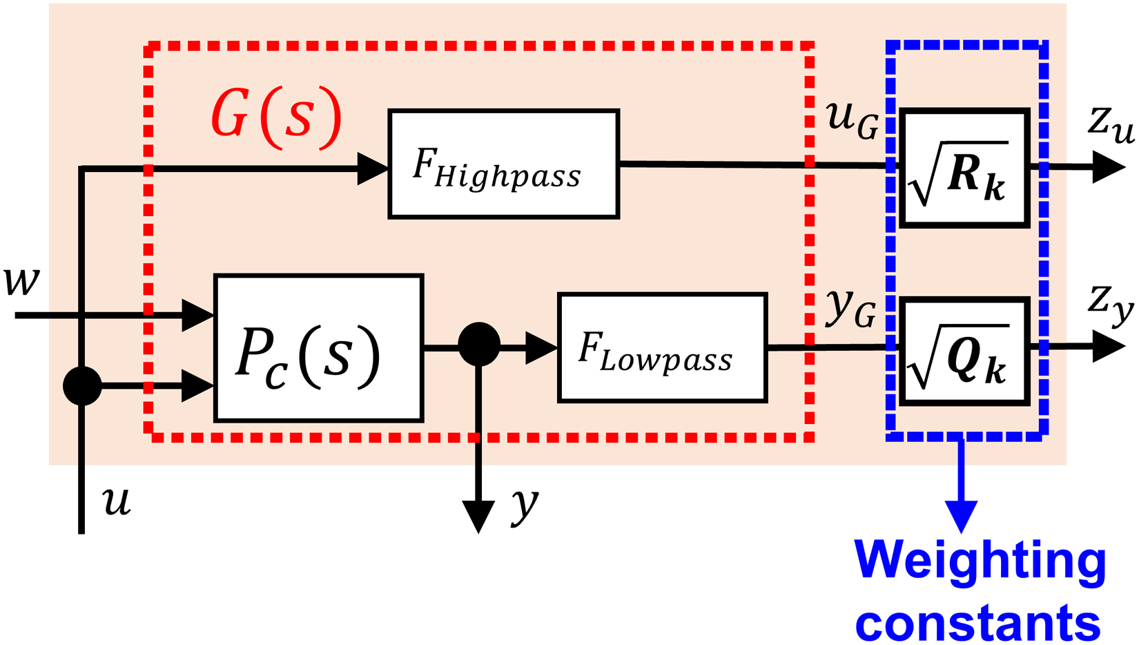
Generalized plant used to design the contact mode controller.
From the external input to
When evaluating the 

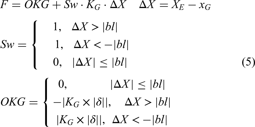
Backlash compensation by simple control mode switching algorithm
During the backlash mode, the aims of our backlash compensation strategy are as follows:
to push the backlash to travel from negative contact toward positive contact as soon as possible for good responsiveness; to reduce the impact (shock) when the drivetrain is transferred from the backlash mode to the contact mode and the backlash traversal finishes by soft landing.
To meet these competing requirements, the compensation algorithm based on switching of the control modes is applied to the baseline
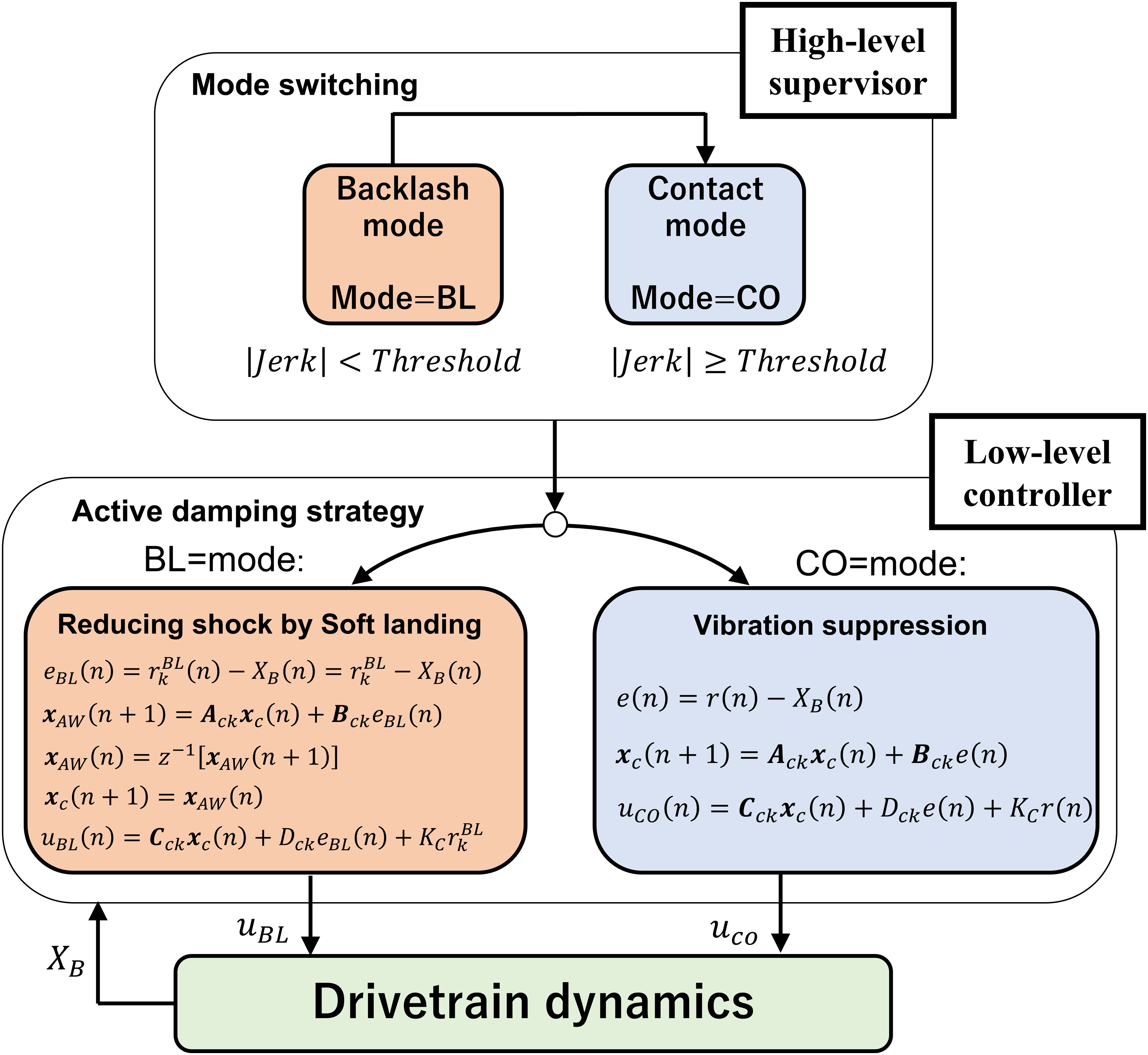
Simple control mode switching algorithm.
In equations (8) to (10) and Figure 4, as the contact mode controller that operates during the mechanical contact, the normal
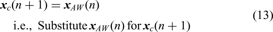
In equations (11) to (15), the compensation during the backlash traversal is performed by the backlash mode controller. Here, by switching the target signal
Due to this compensation, we can prevent unnecessary excessive control inputs during the backlash traversal, resulting in a considerably reduced shock with a collision in the backlash. Refer the previous studies13,32 for further details on the basic idea of this compensation.
Note that the same single
(Contact mode control):


The soft-landing reference
Auto-optimization scheme for the backlash and contact mode controllers
SPSA with norm-limited update vector
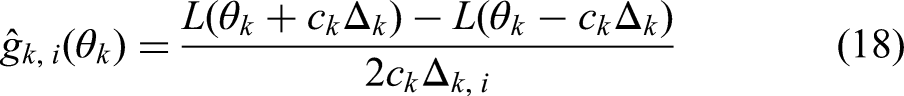
The proposed tuning approach employs SPSA because of its calculation efficiency. The algorithm of SPSA updates a design variable 


However, several researchers have indicated that the computation stability should be improved to apply SPSA for practical applications.
45
An effective approach is to explicitly limit the updating amount of design variable.
45
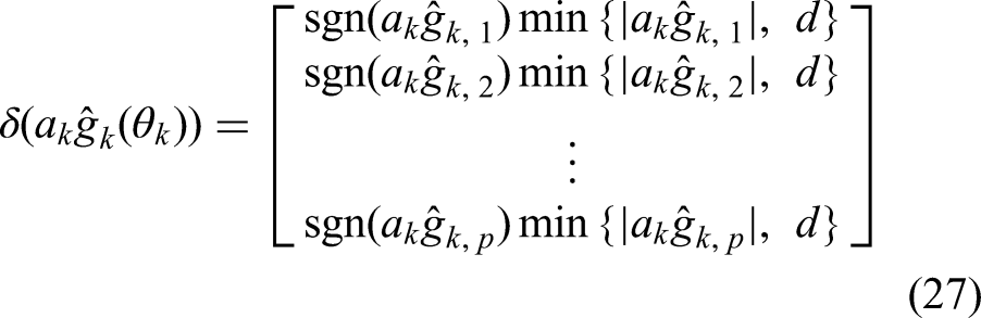
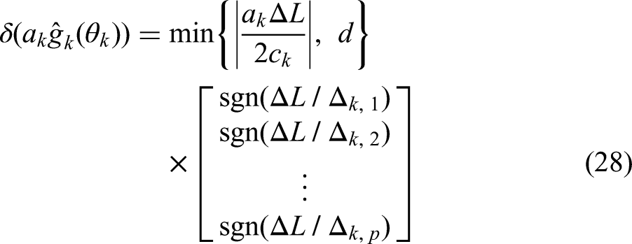
Therefore, the term 

Norm-limited SPSA-based parameter tuning scheme
For the backlash mode and the contact mode, a parameter tuning scheme is newly proposed on the basis of NLSPSA. The tuning scheme is given in Figure 5. In the following, “design variables (
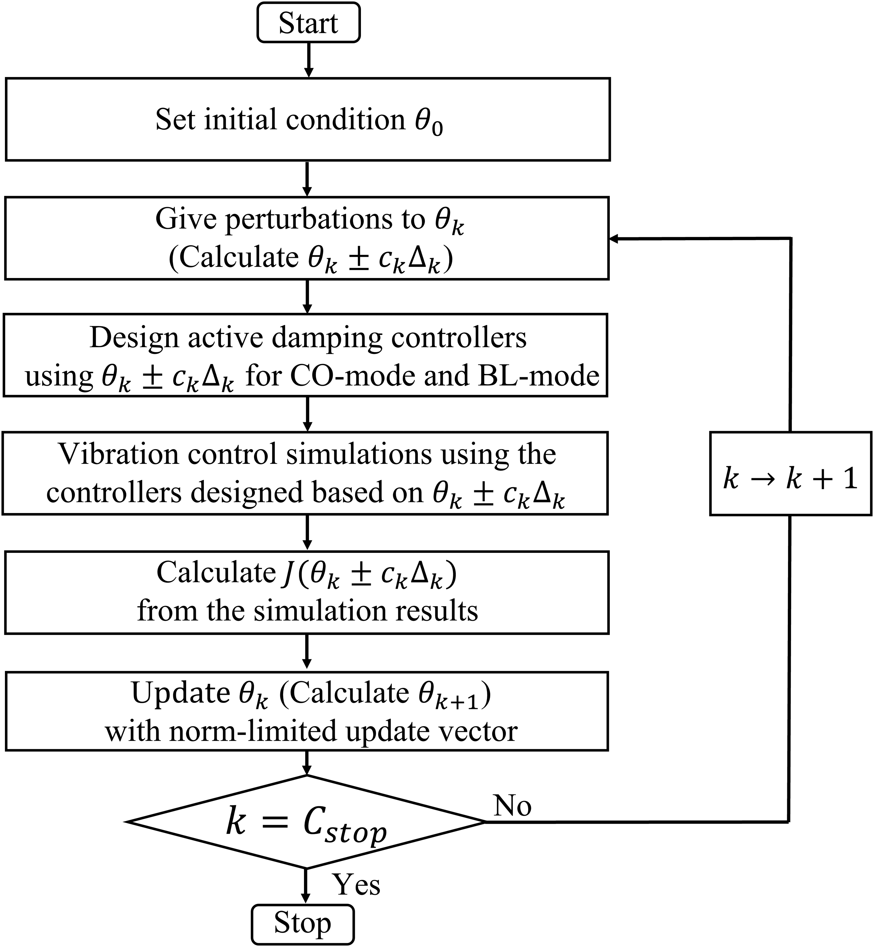
Tuning scheme for the controller design parameters using SPSA with norm-limited update vector. SPSA: simultaneous perturbation stochastic approximation.
An advantage of the proposed method is that both the contact mode controller (i.e., the
Tuning parameter expression
The proposed method automatically tunes all of 


Loss function in optimization
The proposed tuning design uses the loss function 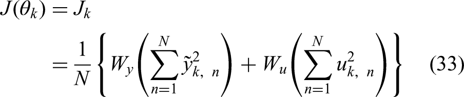
Parameter tuning condition
Table 2 lists the conditions for NLSPSA shown in equations (17) to (29). They are determined according to the guideline on SPSA implementation. 41 The simulation time in each iteration is 4.0 s.
Conditions for NLSPSA in the proposed method.
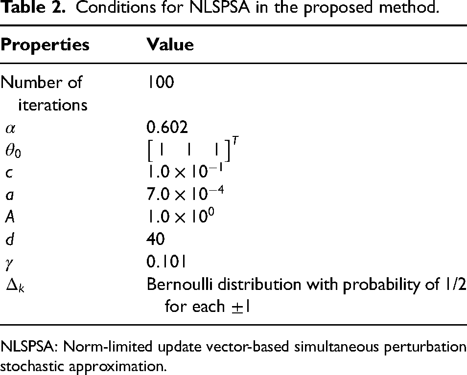
NLSPSA: Norm-limited update vector-based simultaneous perturbation stochastic approximation.
Tuning results
Here, the tuning results obtained by the proposed method are discussed. Figures 6 and 7 show the tuning histories of each tuning parameter and the value of
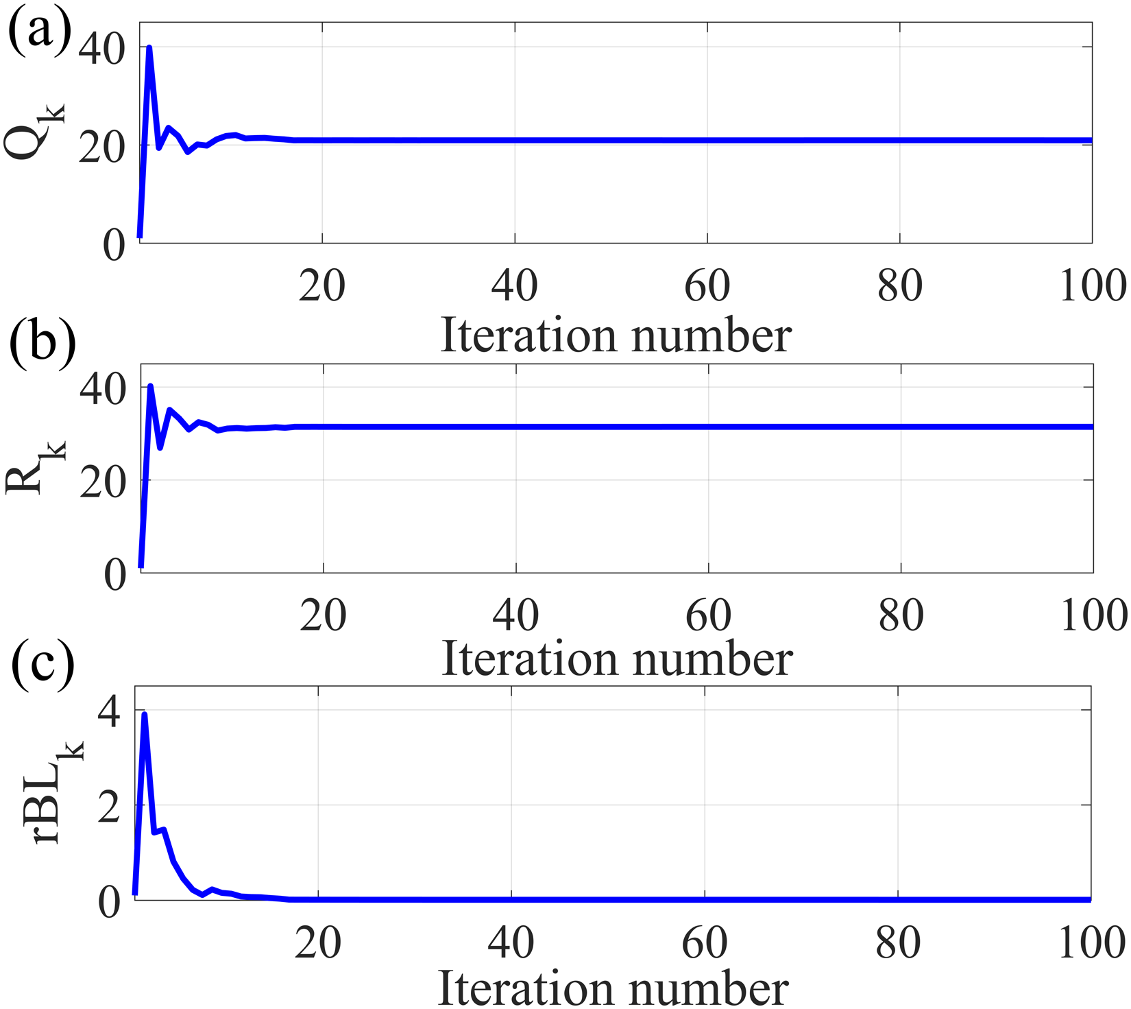
Tuning history of each tuning parameter: (a) Qk; (b) Rk; and (c)
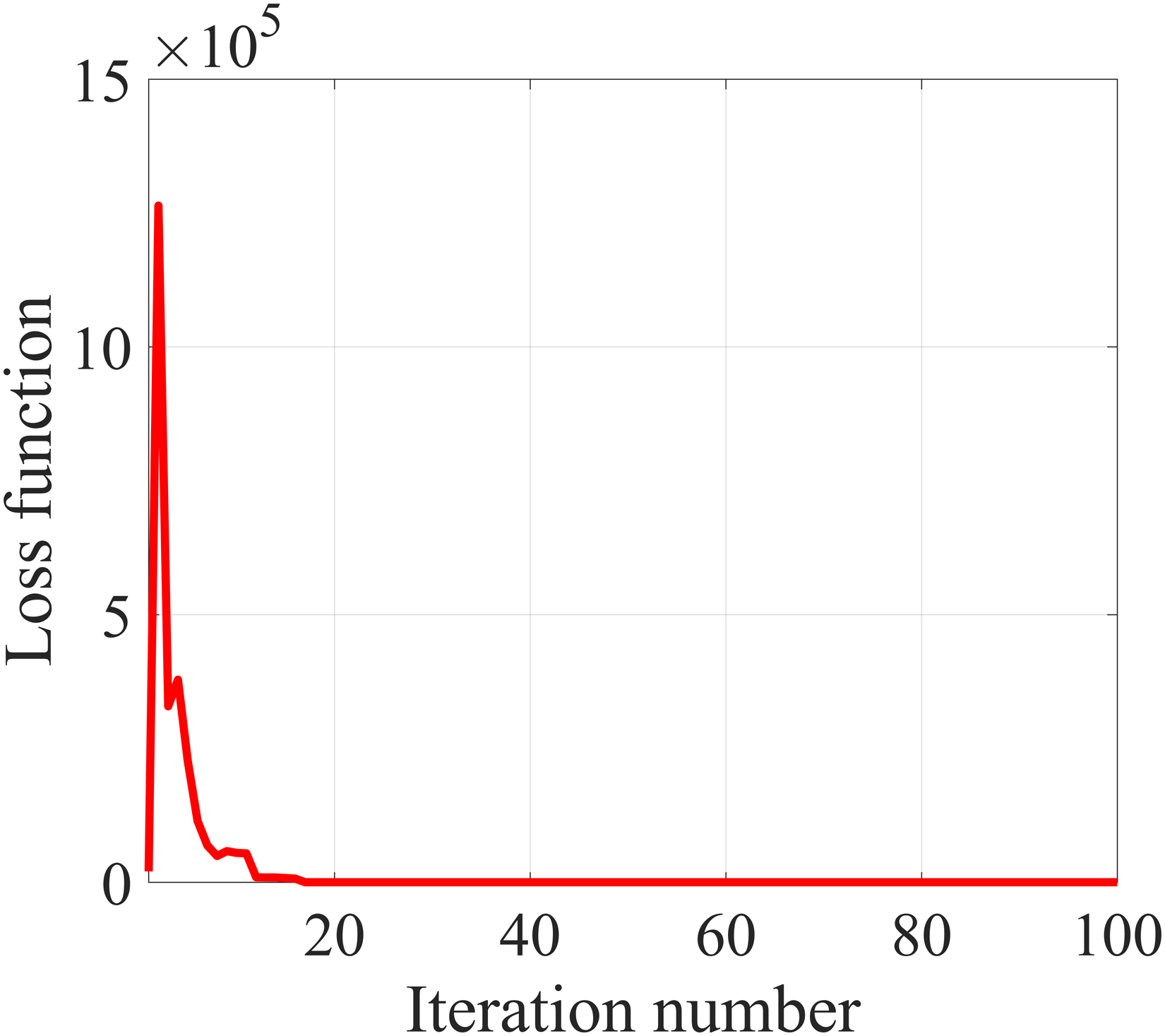
Tuning history of the loss function.
Figure 7 means that the auto-tuned (resultant) controller suppresses vibrations sufficiently. The successful tuning history is observed in Figure 7, where the initial large value of
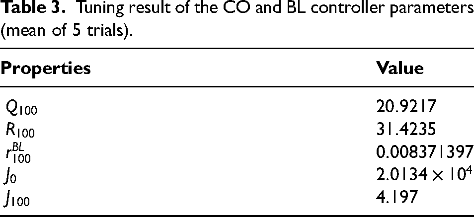
Tuning result of the CO and BL controller parameters (mean of 5 trials).
Experimental verifications
Setting of experimental verifications
In this study, the active damping system is implemented on the experimental system, and the effectiveness is validated using the actual test device. Figure 8 shows the closed-loop diagram of the experimental verifications. The aim of the controllers is to damp the vehicle vibration
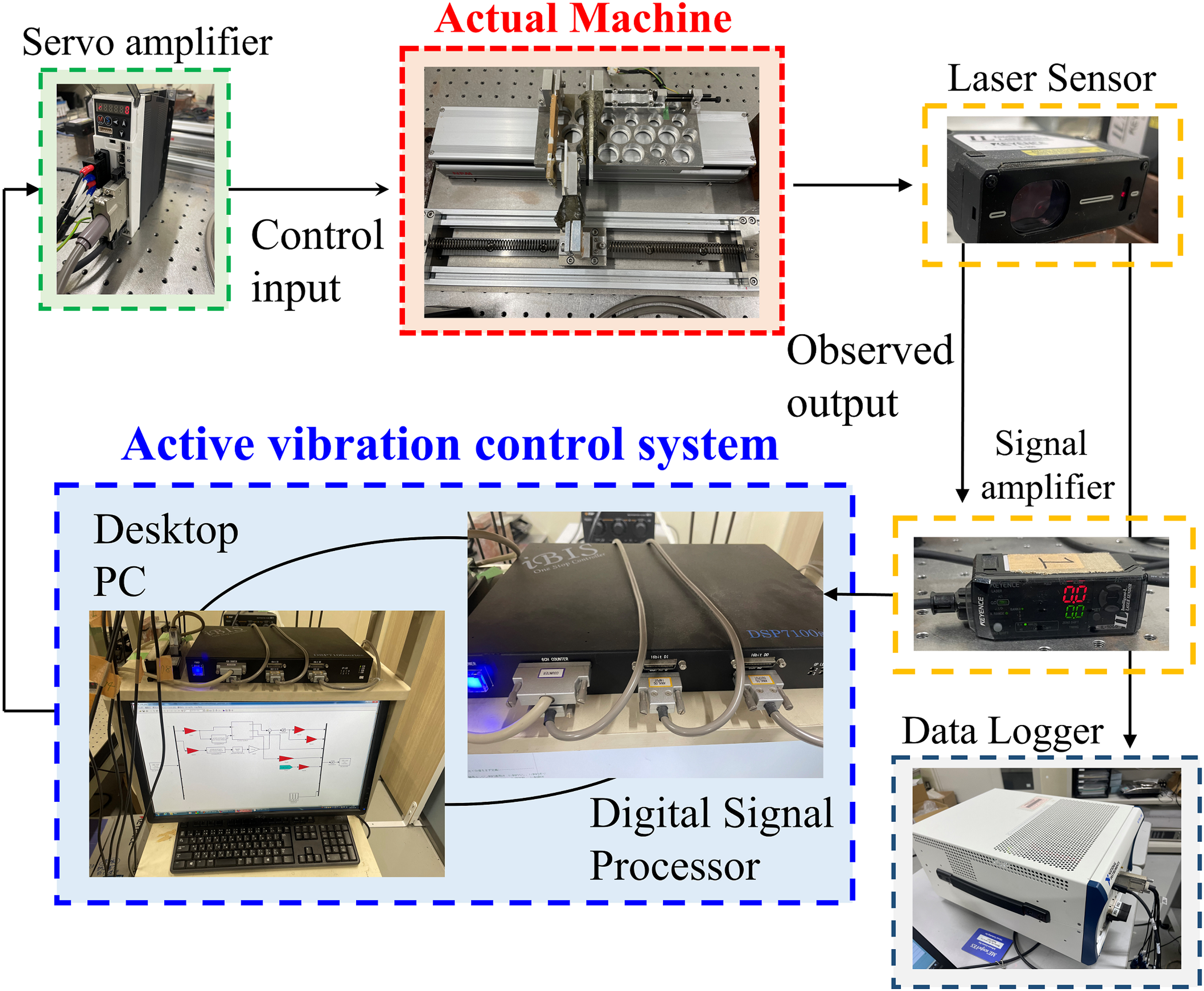
Closed-loop diagram of the experimental system.
Experimental results and discussion
Figure 9 shows the experimental results. The upper and lower graphs show the time responses of the vehicle body vibrations and the control inputs, respectively. The black line represents the response without any active vibration control. The green line represents the ideal response to be realized. The red line represents the experimental result obtained by the proposed method.
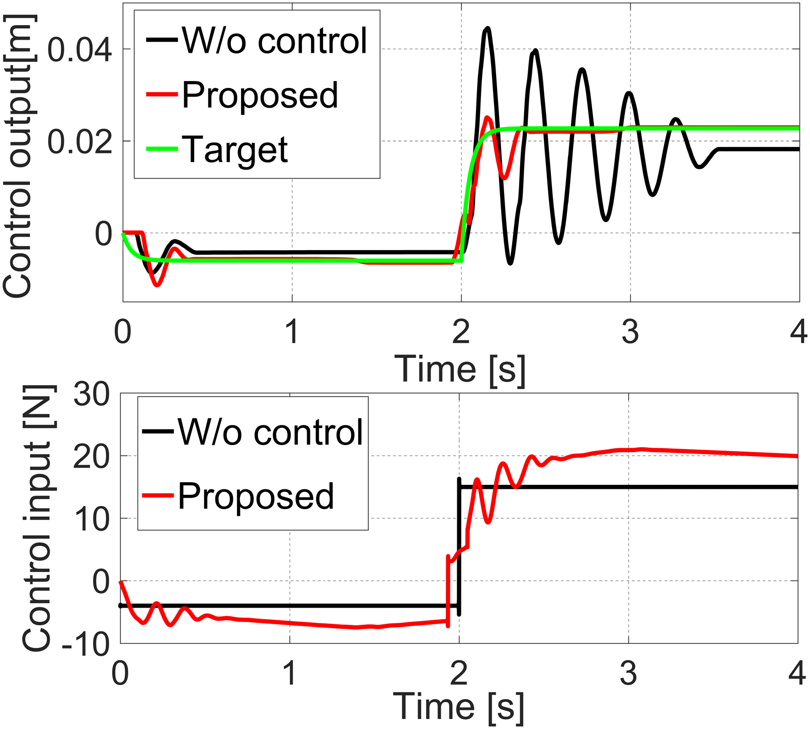
Vehicle body vibration response and control input measured by the experimental verification.
Figure 9 clearly demonstrates the high control performance achieved by the proposed active damping strategy. Compared to the open-loop response represented by the black line, the excellent transient characteristic is realized as indicated by the red line, making the controlled result close to the ideal target response. The vibration appearing after 2.0 s indicated by the black line is hardly suppressed, whereas that indicated by the red line is considerably attenuated.
According to the control input values near 2.0 s during the backlash traversal, we can see that the controller successfully switches from the backlash mode to the contact mode.
Comparison with the case without backlash compensation
For comparative investigations, only a
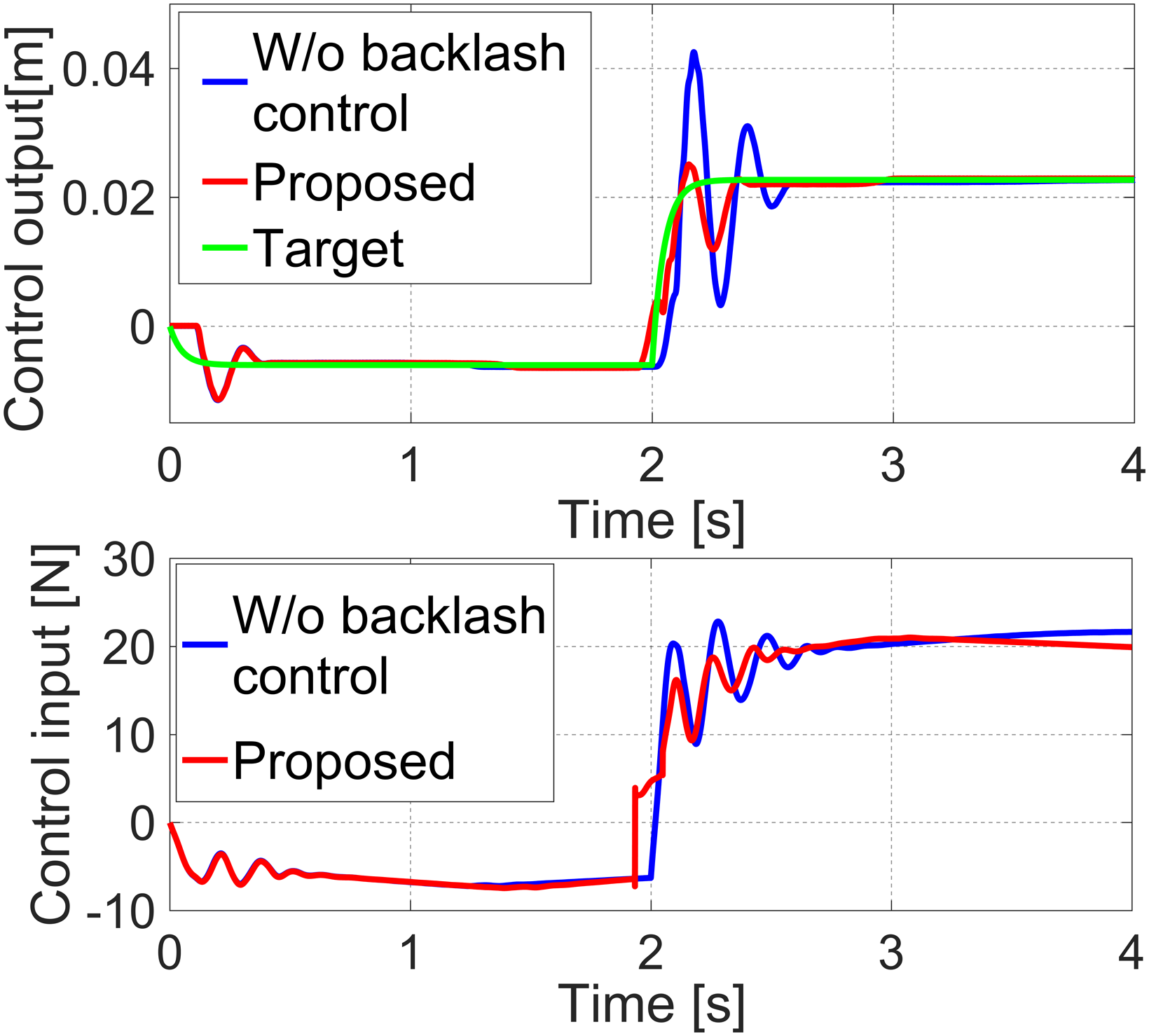
Comparison between the proposed system and case without compensation for backlash.
The blue line shows a large overshoot as well as residual vibrations between 2.0 s and 3.0 s. This poor performance is due to the absence of backlash compensation.
Meanwhile, the proposed method, represented by the red line, improves the performance by suppressing the overshoot and residual vibration amplitude. This result proves that the aim of our backlash compensation strategy is achieved by
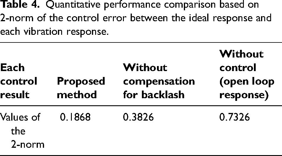
Table 4 summarizes the quantitative comparison between the experimental results presented above. The 2-norm of the control error between the ideal response and each vibration response is shown. The notable point is that the smallest value is given by the proposed approach. The 2-norm by the proposed approach is reduced by 51.1688% and 74.4953% compared to “Without compensation for backlash” and “Without control”, respectively.
Quantitative performance comparison based on 2-norm of the control error between the ideal response and each vibration response.
Robustness against plant variation
The robustness of the controller tuned by the proposed approach is verified in this section. For this purpose, a fluctuation of
Figure 11 shows the comparison between the proposed approach and the open-loop response under the fluctuation in the actual backlash. Despite the fluctuation, the high vibration suppression is retained as indicated by the red line.
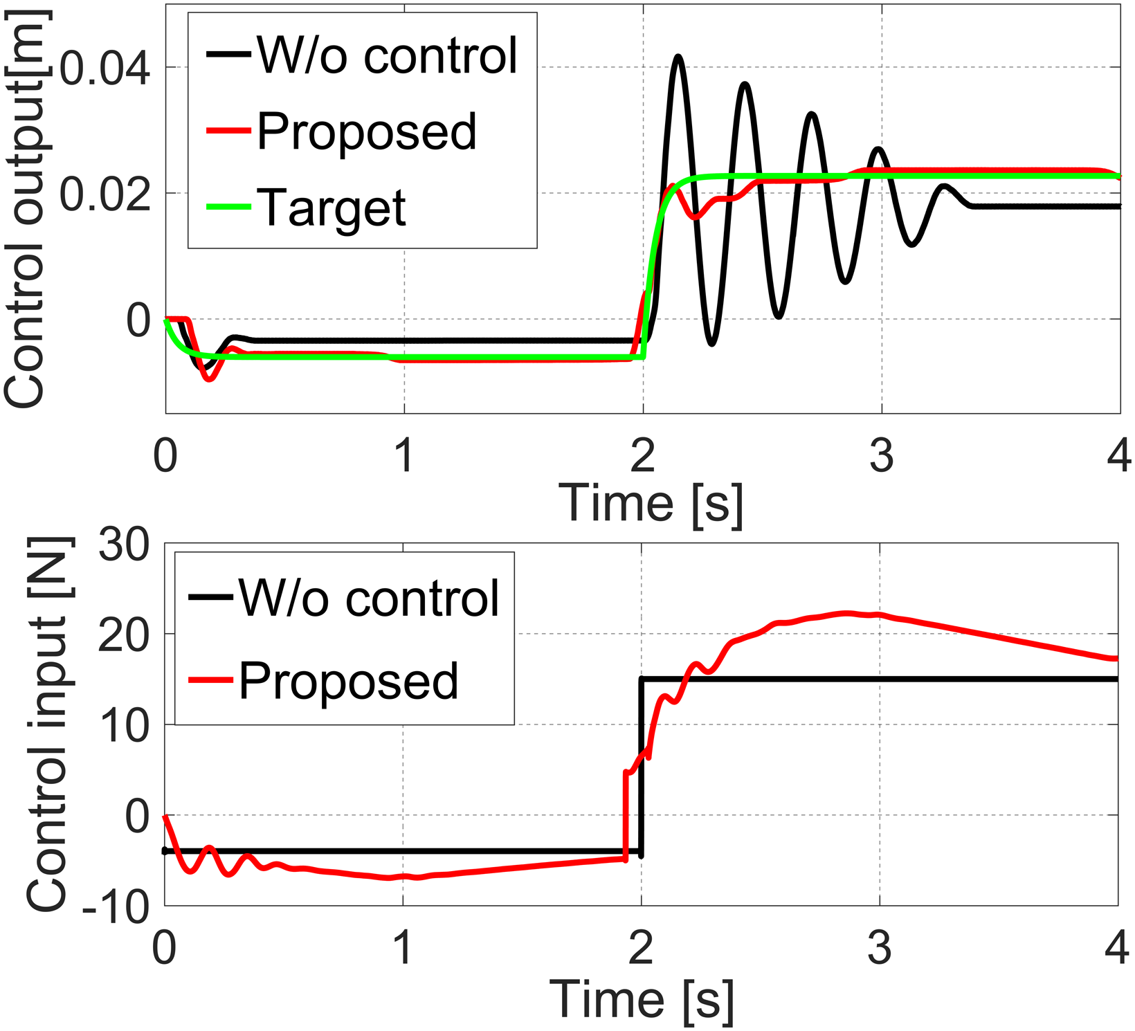
Vehicle body vibration response and control input with the fluctuation of the backlash.
Compared to the case without backlash compensation as shown in Figure 12, the importance of addressing backlash is also observed. The reduced overshoot as well as the lower residual vibrations reflect the robustness of the backlash compensation. Even though the backlash is changed, the jerk can be observed independently of the fluctuation. Therefore, it allows switching of the control modes, leading to robust backlash compensation.
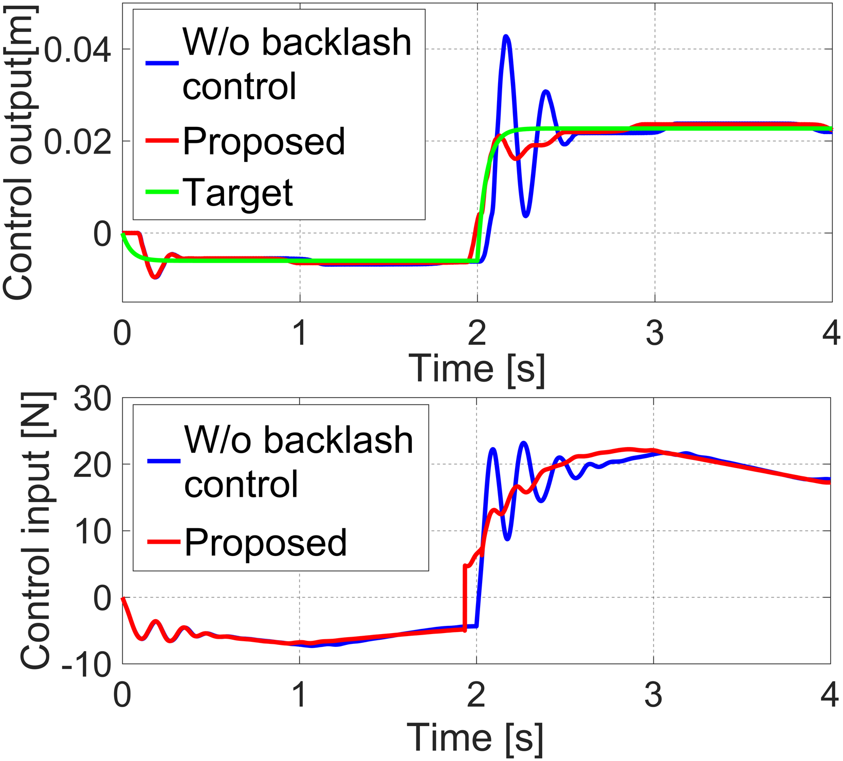
Comparison between the proposed approach and the case without backlash compensation when there is a fluctuation in the backlash.
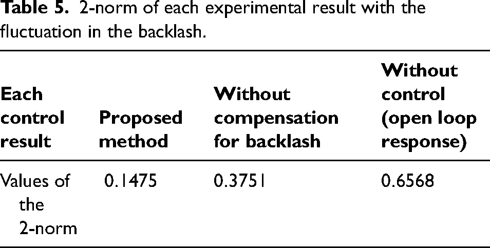
Table 5 summarizes the 2-norm of each vibration response when the backlash is changed. The 2-norm by the proposed approach is reduced by 60.6790% and 77.5419% compared to “Without compensation for backlash” and “Without control”, respectively. These results quantitatively demonstrate the robust performance of the active vibration controller.
2-norm of each experimental result with the fluctuation in the backlash.
The limitation of this study is that it is necessary to further verify the robustness of the controller tuned by the proposed approach. Severer changes should be considered under additional conditions of the drivetrain dynamics.
Conclusion
For a drivetrain mechanism with nonlinear backlash, this study proposed a norm-limited SPSA-based optimized active vibration controller. First, a basic experimental device reflecting a simplified drivetrain was demonstrated. The mechanism reproduces both the contact mode and the backlash mode. For the contact mode, a model-based
In the future, severer fluctuations will be tested for additional conditions of the drivetrain dynamics. In addition, a more robust controller will be developed by introducing an SPSA-based online tuning mechanism into the active damping strategy.
Footnotes
Declaration of conflicting interests
The authors declared no potential conflicts of interest with respect to the research, authorship, and/or publication of this article.
Funding
The authors disclosed receipt of the following financial supports for the research, authorship, and/or publication of this article: This work was partly supported by the Transmission Research Association for Mobility Innovation (TRAMI) (23B3-01) and the Japan Society for the Promotion of Science (JSPS) KAKENHI (grant numbers 22K20396; 23K13273).