
Abstract
Origami structures have been widely explored in robotics due to their many potential advantages. Origami robots can be very compact, as well as cheap and efficient to produce. In particular, they can be constructed in a flat format using modern manufacturing techniques. Rotational motion is essential for robotics, and a variety of origami rotational joints have been proposed in the literature. However, few of these are even approximately flat-foldable. One potential enabler of flat origami rotational joints is the inclusion of lightweight pneumatic pouches which actuate the origami’s folds; however, pouch actuators only enable a relatively small amount of rotational displacement. The previously proposed four-vertex origami is a flat-foldable structure that provides an angular multiplier for a pouch actuator, but suffers from a degenerate state. This paper presents a novel rigid origami, the self-lock origami, which eliminates this degeneracy by slightly relaxing the assumption of flat-foldability. It includes the earwig wing-inspired origami pattern with inextensible and flexible components. This joint is analyzed in terms of a trade-off between the angular multiplier and the mechanical advantage. Furthermore, the self-lock origami is a modular joint that can be connected to similar or different joints to produce complex movements for various applications; three different manipulator designs are introduced as a proof of concept.
Keywords
Introduction
Origami structures have the potential to enhance robotics in various ways. They can help save space,1–3 reduce energy consumption,4–6 decrease production time and cost7–11 by offering a compact and lightweight structure, and having a simple flat structure that is easy to produce. Hence, by replacing conventional robotic structures with origami structures, robots could take advantage of these benefits. This paper focuses on an origami rotational joint structure that could substitute the traditional revolute joint 12 while offering the advantages of origami.
A variety of origami robots, ranging from legged walkers13–18 to grippers and more,19–23 make use of the simple fold as a rotational element in order to build up more sophisticated robots. The simple fold is ideal for these purposes because it is simple and compact. Tendon-driven robogami 24 joints with adjustable stiffness using shape memory polymer (SMP) layer could rotate along multiple axes. The joints are flat-foldable and modular. However, the rotational motion has a limited range which depends on the solid panels’ thickness and the flexible joint between the panels.
Many rotational joints have been developed beyond the simple fold; some can create limited rotation in multiple different directions.25–27 Pneumatic origami rotational actuators can produce significant force, but are large and cannot be flat-folded for deployability.
28
Foldable designs for hinge and pivot joints have been proposed
29
. These joints can be combined to generate desired kinematics, but they are relatively complicated and cannot be flat-folded. Curved patterns can add stiffness to an origami structure capable of rotational motion.4,30–32 A curved kirigami joint has been shown to achieve rotational motion up to almost
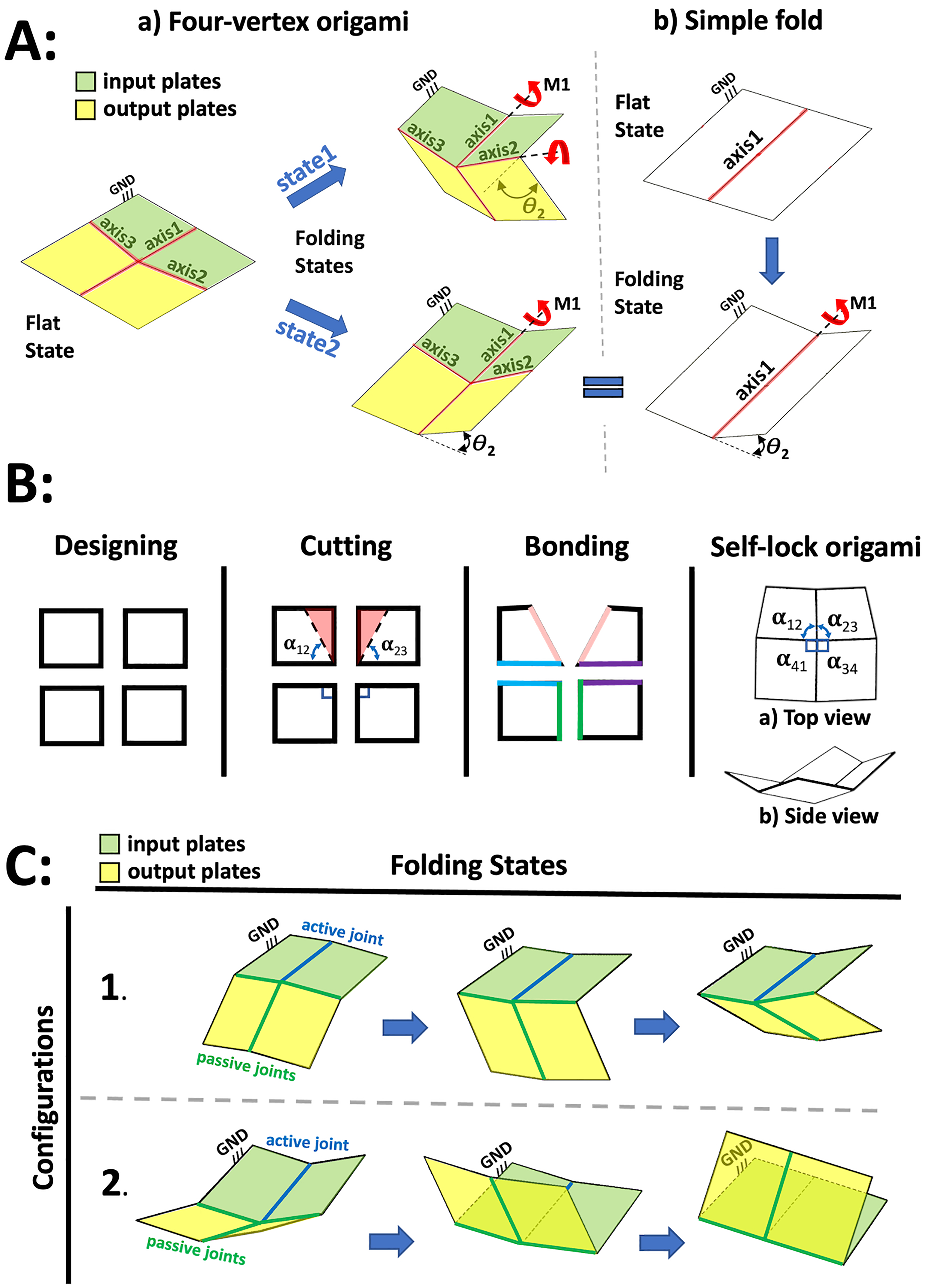
A potential candidate to substitute the traditional rotational linkage in an origami robot is the four-vertex origami, which generates 8.4 times more rotational angle than a simple fold for a given actuator displacement. 34 This is crucial when using pouch actuators, which pair naturally with flat-foldable or semi-flat-foldable origami due to their flat shape when deflated, but have a limited range of angular movement. 35 It can be manufactured in different shapes and sizes all the way down to the thickness of a sheet of paper, allowing its weight and size to be adjusted based on the application. Furthermore, it can be assembled with other origami joints to create complex movements. 36 However, such an origami is underactuated when folded from flat, and in fact has a degenerate state equivalent to a simple fold (Figure 1(A)). The uncertainty of which fold line will be activated when the pouch motor is inflated increases the chance of failure in the joint’s rotation.
Faber et al.
37
designed an earwig-inspired spring origami joint similar to the four-vertex origami but with central angles around the common vertex summing to less than
In this paper, we introduce an innovative rigid origami design known as the Self-Lock Joint. This joint draws inspiration from two distinct sources: the four-vertex origami 34 and the earwig-inspired joint. 37 Through a strategic reduction in the central angles of the four-vertex origami, we effectively eliminate the degenerate state associated with this pattern. When combined with the assumption of a fold line made from non-extensible materials and with zero gaps, the Self-Lock Joint exhibits a wide range of remarkable capabilities. Our motion analysis highlights pressure conservation, as rotational motion occurs at lower pressures compared to a simple fold. The reduced angles lead to a singular origami configuration (downward or upward), resulting in the incorporation of a built-in state-lock mechanism. Furthermore, the moment analysis demonstrates that the origami generates high moments near the folded states. The joint’s versatility is evident in its ability to facilitate both downward and upward rotational motion within the structure. To showcase the practical potential of this joint, we employ it to develop deployable manipulators capable of rotational and translational movements, serving as a proof of concept.
Design
The self-lock origami is a rigid origami whose central angles sum to less than
Motion simulation
For origami assembly, joint constraints are necessary. Various shapes are created by cutting angles in different origami plates’ positions: any of the origami’s four central angles can be reduced in order to achieve the self-locking property. Although Figure 1 demonstrates only one of these, 16 different configurations were considered: four where the central angle was subtracted from both sides of a single fold line (Figure 2), and twelve other configurations shown in the supplemental material. Note that only cuts reducing the central angles are considered, as an origami could have various shapes around its edges without compromising its motion. 34
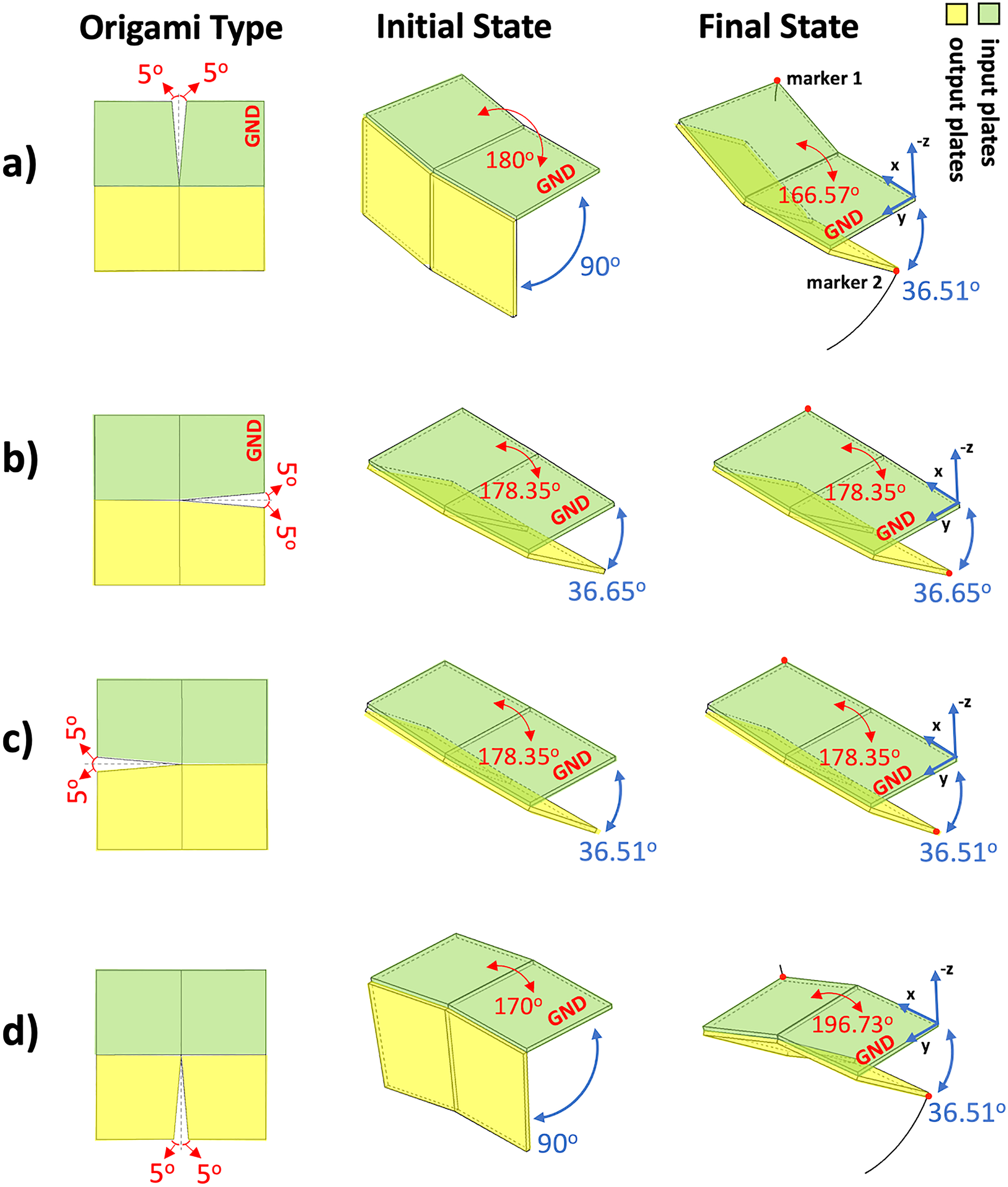
Four different possibilities for the reduction of the central angle in the self-lock origami. The input and output plates are highlighted with green and yellow colors, respectively. Initial state: Closest possible configuration to the flat state of the input plates. Only origami type a achieves a flat state for the input plate,
The structure of the grounded plate 1, connected to plate 2, is equivalent to a simple fold (Figures 3 and 4(a)). Therefore, the origami’s input angle,
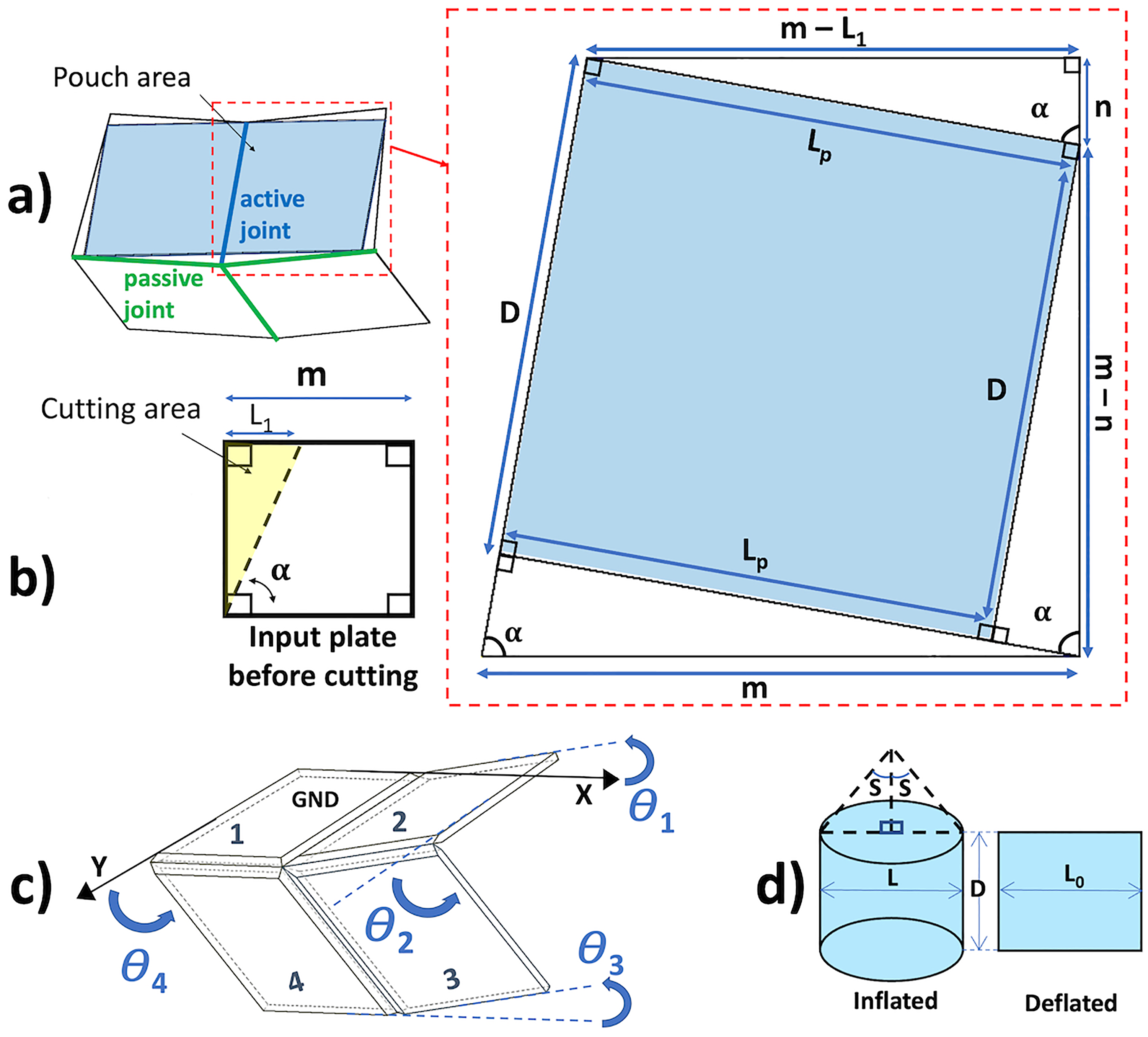
(a) Schematic representation of the self-lock origami with attached pouch motor. The pouch has a rectangular shape before inflation, whereas the plates are trapezoidal. The pouch dimensions
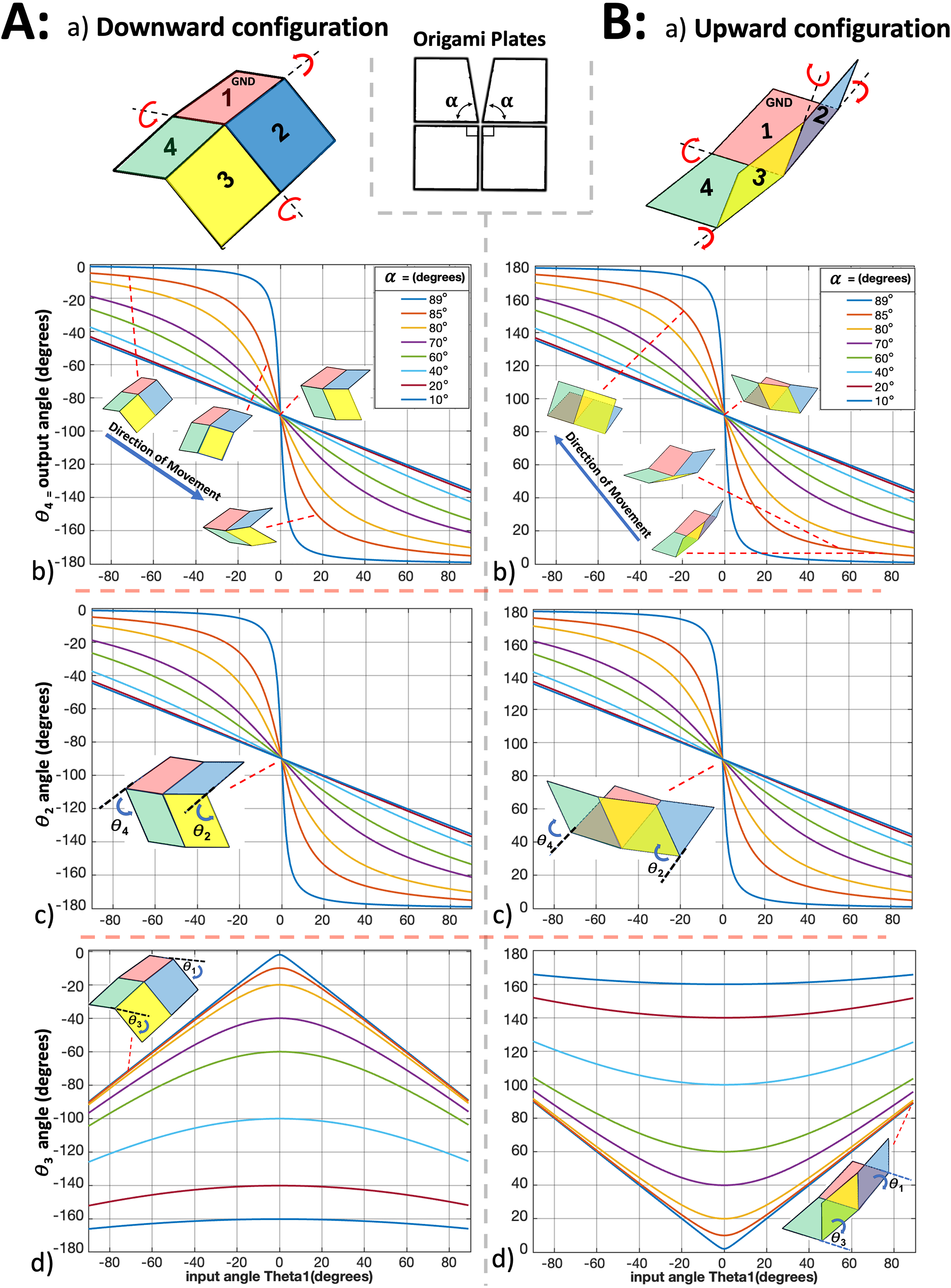
Analytical kinematics of the self-lock origami. Configurations 1 and 2 are shown in columns A and B. (a) Diagram of the origami joint, with plates numbered and color-coded. As plate 2 moves towards plate 1, plates 3 and 4 experience either downward or upward motion depending on the configuration. (b–d) the kinematic angles
Various motion simulations were implemented using the contact solver of Autodesk Inventor 2019 to find an origami that could maintain a flat configuration between its input plates at its initial state and obtain the maximum rotational movement (optimal performance). Achieving a flat state by the origami’s input plates could offer a more simplified model and better control by the pouch motor’s actuator. The pouch motor will be able to maintain a zero pressure state (no inflation) and provide a known shape and dimensions at the initial state for the modeling.
In all simulations, plate 1 is a grounded link at a fixed position with its outer corner at the origin. Gravity is neglected for simplicity and consistency with the analytical model. The kinematics of the mechanism are simulated by sweeping the input angle between what the “semi-flat” and “maximum possible fold” (MPF) state. The semi-flat state is defined as the state where the absolute sum of all the angles between origami plates is at its maximum. Since the origami models to have zero thickness, they are kinematically capable of achieving fold angles more extreme than a real origami, so the MPF state is chosen to set the angle
Figure 2 shows origami types defined by different cutting positions. The green and yellow plates are input and output plates respectively. The “initial state” pictured in Figure 2 shows the closest angle that origami’s input plates could get to
In order to obtain an origami that is symmetrical and also capable of reaching a state with fully flat input plates, origami type a is used in the remainder of the paper. If the flat state of the input plates is not considered, all the origami types provide almost the same amount of rotational motions in slightly different directions. This is discussed in the supplemental material (together with an expanded version of Figure 2) using an algorithm described previously. 34 Additional fold types not pictured were also considered. Certain of these types could also reach a state with flat input plates, but type a is used due to its symmetry, which simplifies modeling.
Modeling
The self-lock origami is a single-vertex origami with four fold lines, meaning that it has a single degree of freedom.38–40 As shown in Figure 1(C), the same components can be assembled into two distinct configurations whose motions are vertical mirrors of each other. These configurations can be used in applications to achieve motion in two different directions.
In this section, the relations between the origami’s angles, output moment, input moment, and the pressure in a pouch actuator are developed. Pouch actuators are a practical choice for the self-lock origami because they are planar and compact. They can be treated as a layer of the origami during layer-by-layer construction of an origami robot by programable machines. 35 The mechanical work of the pouch motor inflation converts into the deformation of its shape and changes in its curvature length. These cause angular motions in the simple fold (a hinged structure) that it has been attached to. 35
Origami structure as a spherical mechanism
The kinematics and dynamics of single-vertex rigid origami can be studied by noting that they are mechanically identical to spherical mechanisms,41,34 for which a detailed theory exists. 42 To do this, the origami folds between the plates are treated as revolute joints. Then, since each plate of a single-vertex origami is assumed to be inflexible, the single vertex acts as a fixed center about which the four plates move as the bars of a spherical four-bar mechanism.
The first quantity of interest is the kinematic relationship between the input angle

Input and output moments
The pouch motor is modeled as non-extensible with zero bending stiffness. If fully inflated while detached from the origami, it would take a cylindrical form with height
The moments that have been applied to (input moment) or generated by (output moment) the origami are modeled under the assumption of constant air pressures on the system’s pouch motor. Through the integration of a pressure sensor and solenoids, the pressure of the pouch motor can be effectively fine-tuned. Although the experimental setup may introduce certain deviations and errors, for simplicity all models assume a constant pressure. A comprehensive explanation of the control system can be found in.
44
The moments could be calculated using the origami’s input angle. A range of
To estimate the input moment applied to a simple fold (a hinged structure), Niiyama et al. developed equation 4.
35
The self-lock origami’s input plates have a structure similar to a simple fold, so this equation can be used to calculate its input moment. Based on the proposed origami structure, the equation relies on the origami’s input angle
Model results
This section demonstrates the kinematics of the self-lock origami as well as its input and output moment, including how these quantities and their relationships change with
The closer
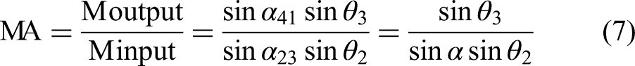
Figure 5 illustrates the theoretical curves 4,7 of input moment and mechanical advantage as a function of
Mechanical advantage of the self-lock origami for a variety of values of
The figure displays curves corresponding to a variety of different values of
Note that the figure does not consider the effect of varying the pouch pressure
Both downward and upward movements have the same mechanical advantage
Manipulators
As a proof of concept, three different origami manipulators constructed from combinations of multiple self-lock origami units are presented. These manipulators can be divided into three categories: Rotational, translation, and modular manipulators. These manipulator concepts can cover a wide range of motions while benefiting from the self-lock structure’s properties, such as compactability, light weight, conserving energy, high-speed rotational motion, and large moment.
Each manipulator is discussed through the results of a kinematic simulation in which the angles of the involved origami joints are swept through a range of angles in order to obtain a desired motion. Dynamics, including gravity, are outside the scope of this section, as are the details of any particular actuation scheme. The rotational and translational manipulators were simulated for different values of the reduced central angle
Rotational manipulator
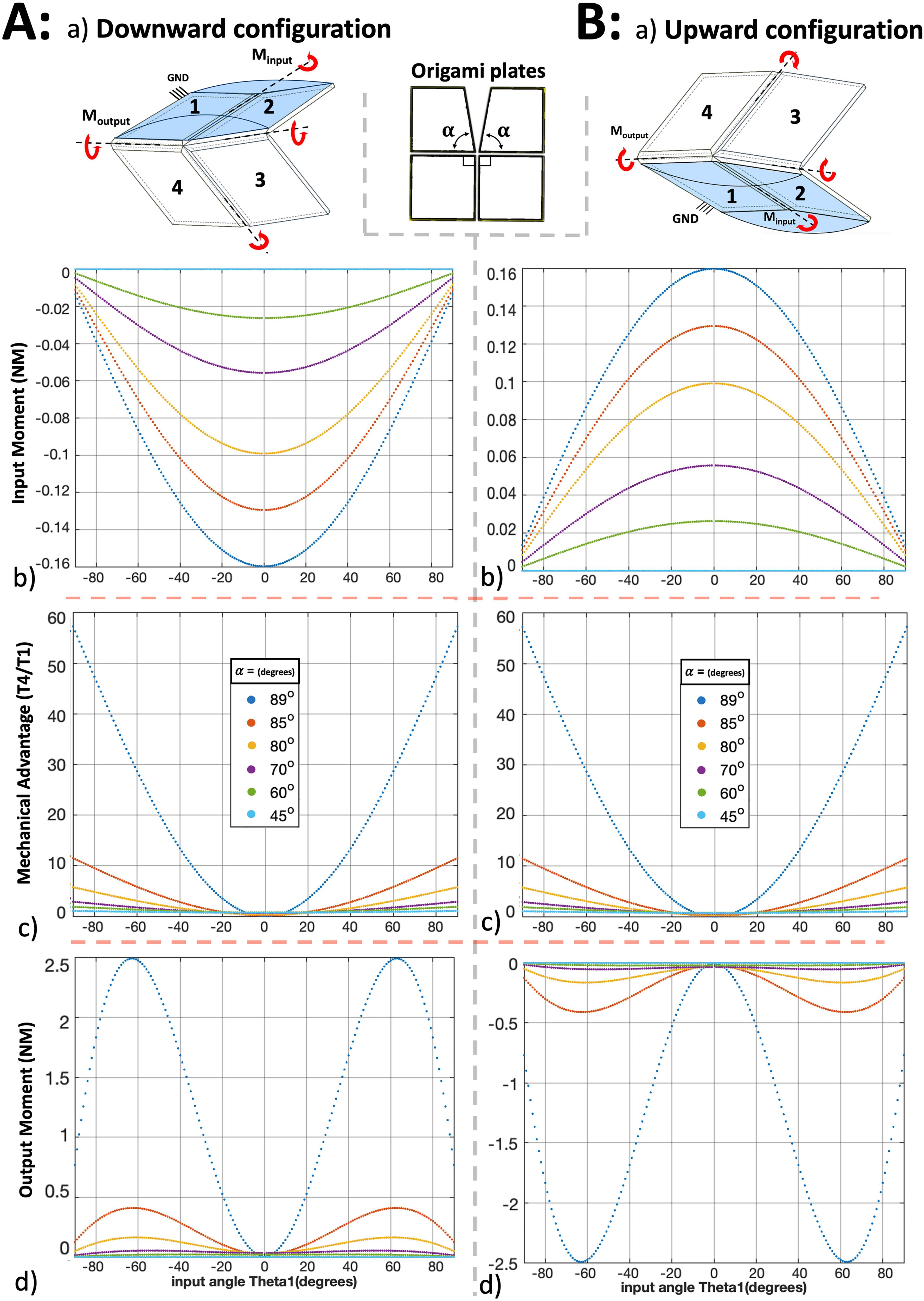
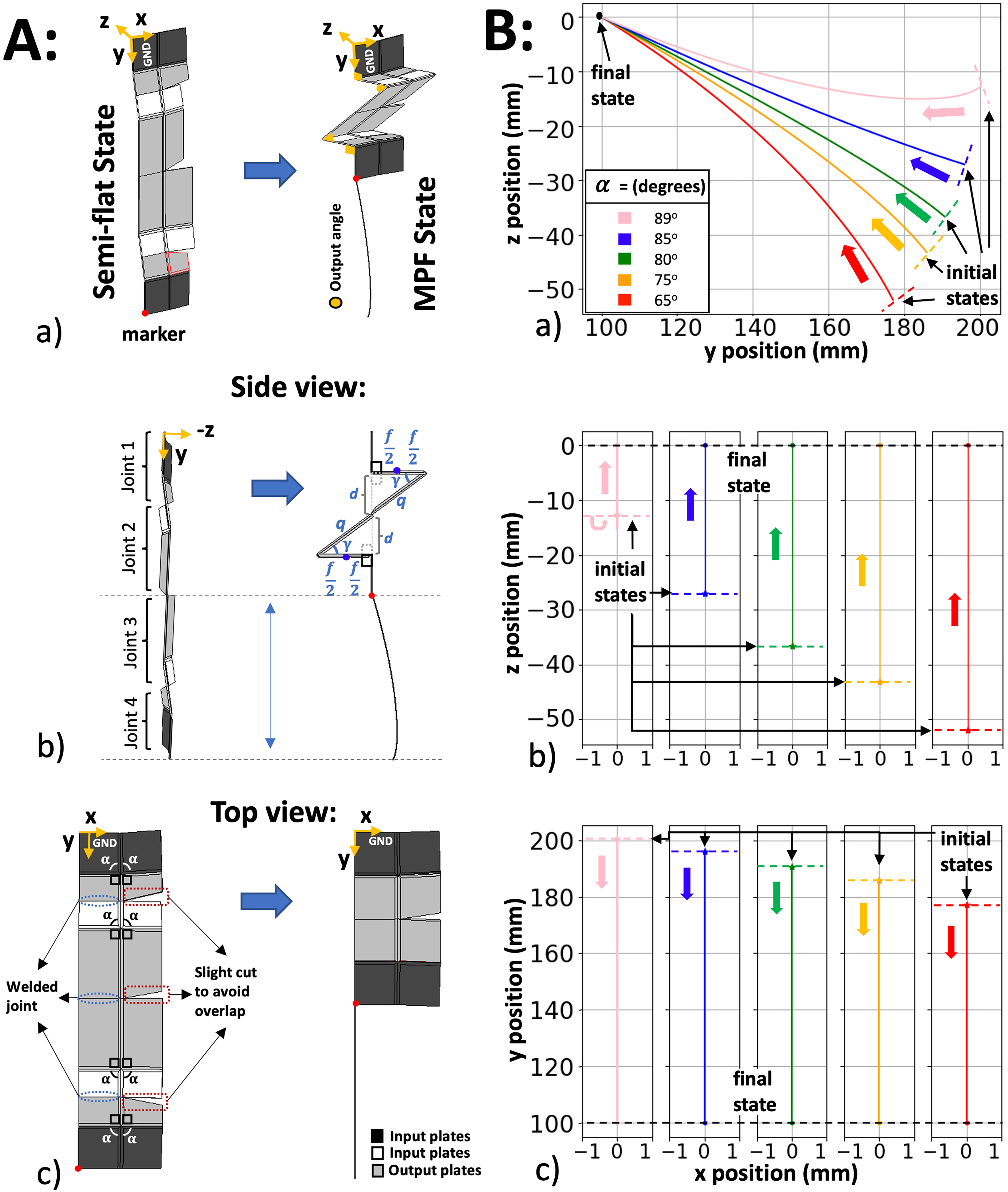
The rotational manipulator shown in Figure 6 consists of two origami units, connected by a welded joint between one of the output plates of the first origami and one of the input plates of the second origami. Connecting them on more than one plate could jeopardise their mobility; the connection method described here leaves each origami unit with a single degree of freedom. There is a possibility of a collision between the first origami’s output plates and the second origami’s input plates while the manipulators move. To avoid this, the plates are cut at a slight angle in those problematic areas (Figure 6Ab). Cutting them does not affect the manipulator’s movements because the plates’ central angles are unaffected. The motion of the manipulator is given in terms of the position of a designated end effector on one corner of the second origami’s output plate, indicated in Figure 6(A) with the red dot labeled “marker.”
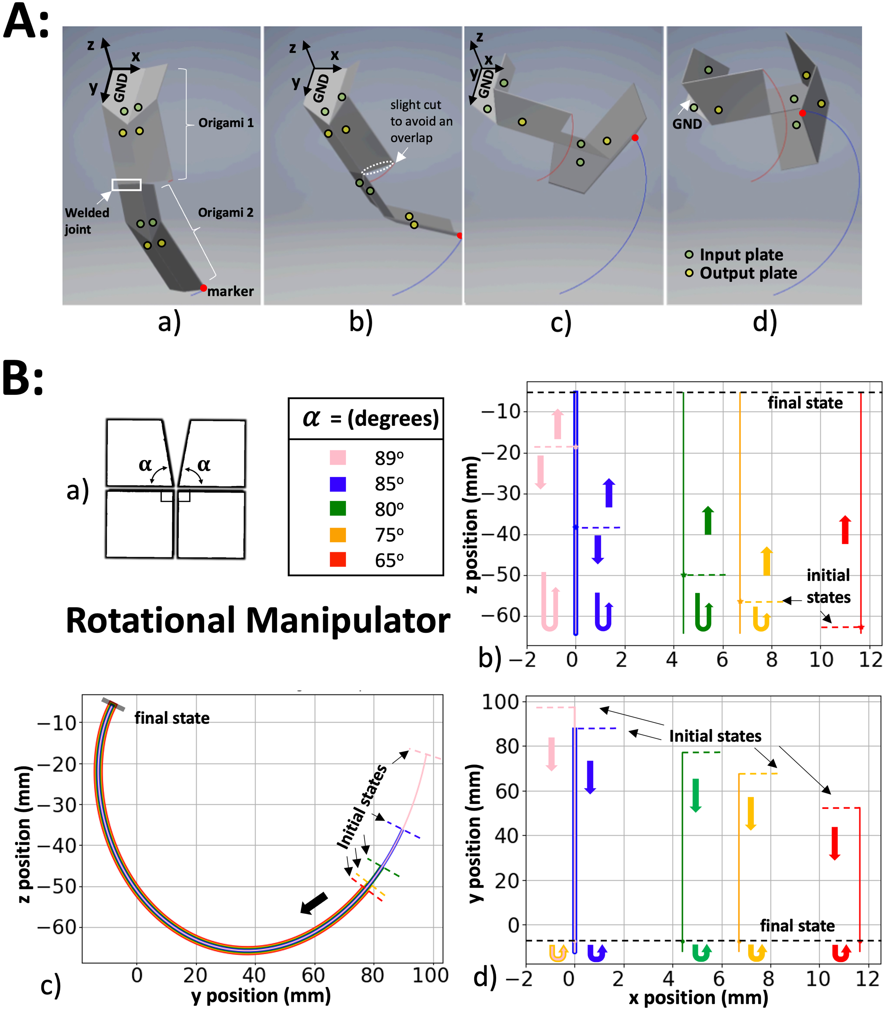
Both of the origami making up the manipulator are constructed in the downwards configuration. Figure 6(A) gives the coordinate system of manipulators and shows the curling motion in 3D. Figure 6(B) shows the planar projection of this movement onto the
The five manipulators with different values of
Translational manipulator
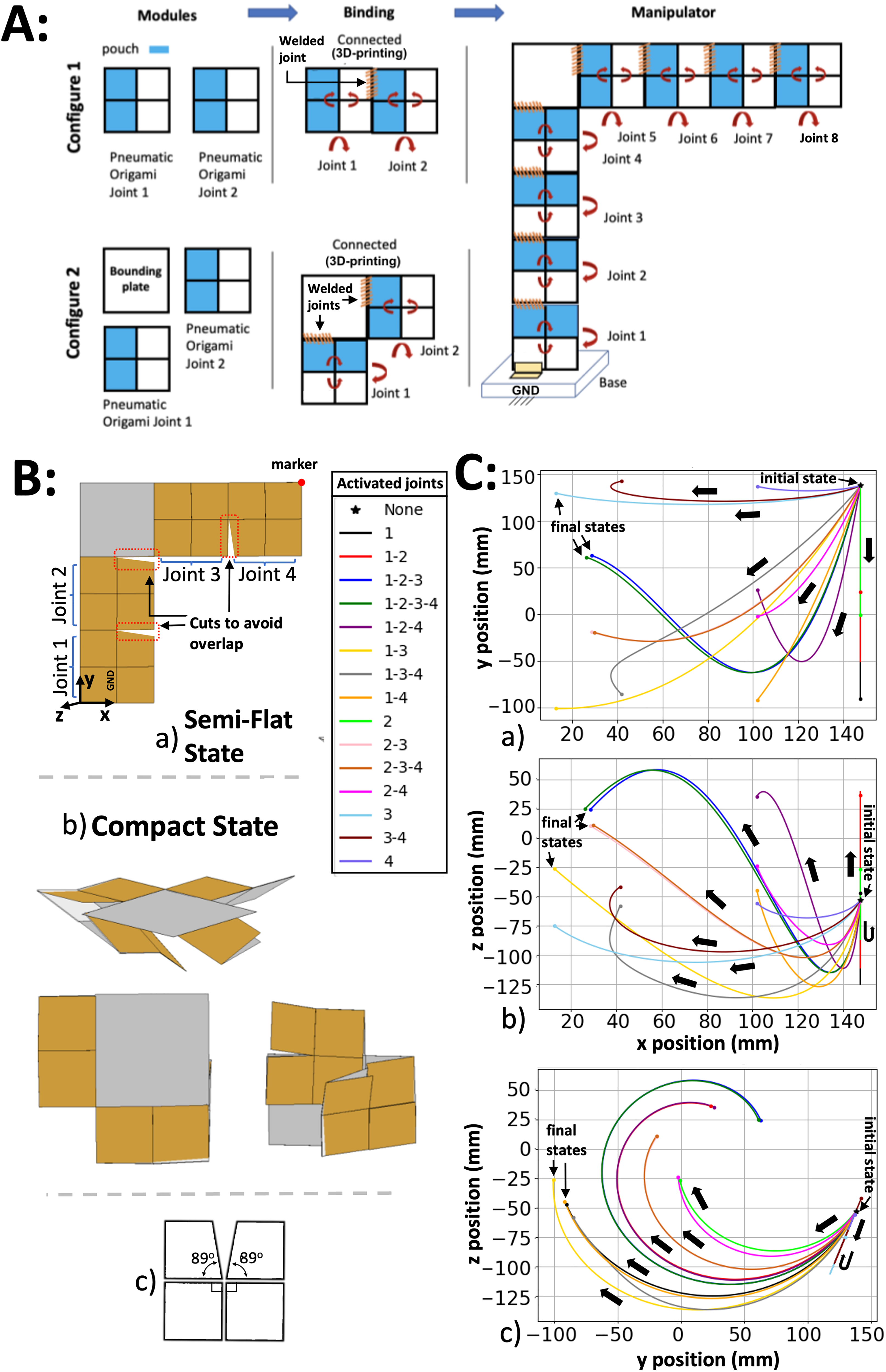
The translational manipulator shown in Figure 7 is constructed from four separate origami units alternating downward and upward configurations. This is necessary in order to enable the “zigzag” state depicted in Figure 7Aa. To obtain the closest possible motion to a linear translational movement, the manipulator’s geometry is required to be symmetrical. Figure 7Ac shows the location of these connections and cuts.
Similar to the rotational manipulator, the origamis are connected on only one of their plates to retain the full number of degrees of freedom, and some perimeter cuts are made to avoid overlapping between the origamis’ movements. This manipulator is the only case where plate length deviates from the previously fixed 25 mm, as indicated in Figure 7Ab. The first and last plates have length 25 mm, but the lengths of other plates were derived geometrically. The MPF angle
Figure 7(A) shows the initial and final states of the
The two-dimensional plots of the manipulators’ movements using a marker and defined reference frame are presented in Figure 7(C). The main translational movement occurs along the
Modular manipulator
Both manipulators could be combined or their constituent origami units could be actuated in other permutations in order to obtain a combination of translational and rotational motions which could be used for complex tasks. Using the origami design in a modular structure could provide the opportunity to create and mimic traditional robots’ complex movements. This could be useful in exploration, where various motions are required in a limited space. This section explores the possibility of a modular manipulator that combines self-lock origami units in an arbitrary way.
A modular manipulator can be built up from self-lock origami units using two different basic construction cells, depicted in Figure 8(A). The first consists of two origami connected directly to each other with welded joints and small cutouts to avoid self-collision as discussed previously. The second connects two origami via a rigid “bounding plate” interposed between them. This enables connecting the origami plates at different angles to change or increase the manipulator’s workspace. Bounding plates could be designed in different shapes to help the origami robots to explore different locations, but in the present work only considers a square plate equal in size to the origami units. In the binding phase, constraints are defined for the movements in 3 directions or welded joints to create configurations 1 and 2. Then, the last origami joint is connected to a base plate which serves as the ground link.
An example of such a modular manipulator made of
The plots in Figure 8(C) present various possible trajectories which could be taken by this modular manipulator in each of the two-dimensional projections. Each trajectory corresponds to a different sequence of joint activation, indicated in the legend as a sequence of joint numbers. Each joint in the sequence folds from the semi-flat to MPF state, with each fold stopping early if a collision occurs. For instance, activated joints 1-2 refer to folding of joint 1 and then folding joint 2 without overlapping joint 1. The joint activation orders 1-2-3 and 1-2-3-4 have similar motion since after joints 1, 2, and 3 are activated, joint 4 does not have much space for folding.
Across the possible joint folding orders shown, the marker exhibits a large range of motion and a variety of different directions of motion in all three planes. If only the joints on one side of the bounding plate are activated, the end effector trajectory is a straight line. The joint combination 1-2 generates straight-line movement in both the
One of the advantages of using origami in modular manipulators is the ability to convert them into structures with small volumes due to the joints’ geometries. Manipulators can achieve this by moving their origami into MPF or semi-flat states in different directions. Also, depending on the application, some of the manipulator’s joints can be excluded in order to produce different manipulators. This can even be enforced temporarily, without modifying the manipulator, by simply folding the joints using their actuators and holding them in that state.
Conclusion
Origami structures could be a great substitute for traditional joints where space limitation is the main issue. They could adapt their size and shape based on the available space. These computer simulations and mathematical models illustrate the origami structure’s high performance. Furthermore, as a proof of concept, different types of manipulators have been developed and simulated using the origami joints. Our main conclusions are the following:
In different origami states, their motion’s speed and output moment are more significant compared to a simple fold with the same actuator. Various trade-off in the design of the individual joint are available. For example, increasing the thickness of the origami plates would increase the mechanical strength of the structure, but decrease its flexibility. On the other hand, increasing the soft joint length between the plates increases flexibility while decreasing strength. Investigating these trade-offs is a potential direction of future research. The developed manipulators could produce a variety of rotational and translational motions depending on their origami’s central angles and configurations.
The proposed joint holds significant potential for various industrial applications, particularly in space, where tools’ weight and volume are of paramount importance. This innovation enables the generation of diverse rotational and translational motions, contingent upon the central angle, all while maintaining an exceptional balance between lightweight design and cost-effectiveness. The inherent flat-foldability properties contribute to the simplicity of manufacturing sheet-like structures on a mass scale.
However, it is important to acknowledge one limitation of this study, which stems from the assumption of a revolute joint in the analytical modeling of the design. This may introduce disparities between the experimental outcomes and the modeling predictions. In the future, our research endeavors will be dedicated to devising methods and designs for the production of soft joints, thereby mitigating the dependence on revolute joints. Furthermore, it is worth noting that this paper assumes that joint angles can be precisely set to desired values. For physical prototypes, the implementation of a control scheme becomes imperative. This control scheme would integrate the kinematic model with sensing and feedback mechanisms, aligning the manipulator’s end-effector position with the desired configuration. Looking ahead, our ongoing work will concentrate on the development of practical methods and experimental setups that harness the full potential of this origami joint for real-world applications.
Supplemental Material
sj-pdf-1-pik-10.1177_14644193231216263 - Supplemental material for Modular self-lock origami: Design, modeling, and simulation to improve the performance of a rotational joint
Supplemental material, sj-pdf-1-pik-10.1177_14644193231216263 for Modular self-lock origami: Design, modeling, and simulation to improve the performance of a rotational joint by Samira Zare, Alex Spaeth, Sandya Suresh and Mircea Teodorescu in Proceedings of the Institution of Mechanical Engineers, Part K: Journal of Multi-body Dynamics
Supplemental Material
Footnotes
Declaration of conflicting interests
The authors declared no potential conflicts of interest with respect to the research, authorship, and/or publication of this article.
Funding
The authors disclosed receipt of the following financial support for the research, authorship, and/or publication of this article.
Supplemental Material
Supplemental material for this article is available online.
Appendix
References
Supplementary Material
Please find the following supplemental material available below.
For Open Access articles published under a Creative Commons License, all supplemental material carries the same license as the article it is associated with.
For non-Open Access articles published, all supplemental material carries a non-exclusive license, and permission requests for re-use of supplemental material or any part of supplemental material shall be sent directly to the copyright owner as specified in the copyright notice associated with the article.