
Abstract
Lightly damped non-linear dynamic driveline components are subjected to excitation with rapid application of clutch and/or throttle. Modern thin-walled driveshaft tubes respond with a plethora of structural-acoustic modes under such impulsive conditions, which are onomatopoeically referred to as clonk in the vehicle industry. The underlying mechanisms for the occurrence of this phenomenon are investigated, using combined experimentation and flexible multi-body dynamics under impulsive impact conditions. The coincidence of high-frequency structural modes, coupled with acoustic response is highlighted for the broad-band spectral response of the hollow driveshaft tubes. The cyclic relationship of clonk with the shuffle response of the driveline system is also established for transient decay of the clonk phenomenon. In particular, the multi-body model is used to ascertain the effect of vehicle laden state on the propensity of driveline clonk, an approach not hitherto reported in literature.
Keywords
Introduction
Lightly damped vehicular powertrain system is subjected to a broad spectrum of noise, vibration and harshness. Modern thin-walled light driveshaft tubes in rear wheel drive configuration have high modal structural density, which are often excited by any sharp variation in transmitted torque, particularly under impulsive conditions. 1 Impulsive action occurs with power flow reversal in throttle tip-in or back-out. 2 The surge or fade in power transmitted to the drive-train system often results in fore and aft motion of the vehicle (vehicle shunt), which is coupled with torsional oscillation of the driveline, a phenomenon referred to as shuffle.2–4 With every cycle of shuffle, impact can occur in the multitude of lash zones within the drive-train system, such as in meshing gear teeth pairs as shown by multi-body analysis of Arrundale et al. 5 The same series of events can also be induced by sudden release of clutch. 6 With sufficient impact energy, an elastic wave propagates from the impact site onto the thin-walled hollow driveshaft tubes, which have high modal density. Coincidence of the elastic structural response with acoustic natural modes of the hollow tubes can lead to noise propagation. This phenomenon is onomatopoetically referred to as clonk or clunk.2,7 High-frequency content of the noise spectrum is quite disconcerting and remains a key concern for automotive manufacturers. It is also regarded as an indication of poor built quality and progressively a significant warranty concern. Therefore, investigation of the clonk phenomenon is an imperative issue in powertrain engineering.
This paper presents detailed combined numerical and experimental investigation to study the underlying mechanisms promoting the clonk phenomenon. In particular, a sensitivity analysis is carried out in respect of a variety of vehicle loading conditions which affect the propensity for driveline clonk. Such an approach has not hitherto been reported in literature.
Experimental investigation
Figure 1 shows the experimental rig, comprising driveline of a long wheel base, rear wheel drive truck, with a 4-speed transmission system, driven by a 4-pole electric motor and a programmable inverter control. The rear axle is rigidly mounted with axle resistance imposed by a variable hydraulic system. The applied hydraulic pressure can be varied to represent different laden states of the truck, from unloaded (1850 kg) to fully laden (circa 3500 kg). As the rear axle is rigidly mounted onto the ground, throttle tip-in or back-out clonk condition, emanating from cycles of shuffle would not be representative of vehicle conditions. Therefore, clutch-induced clonk is studied through sudden recorded release of the pedal, hence introducing impulsive torque transience into the transmission system.
The experimental setup.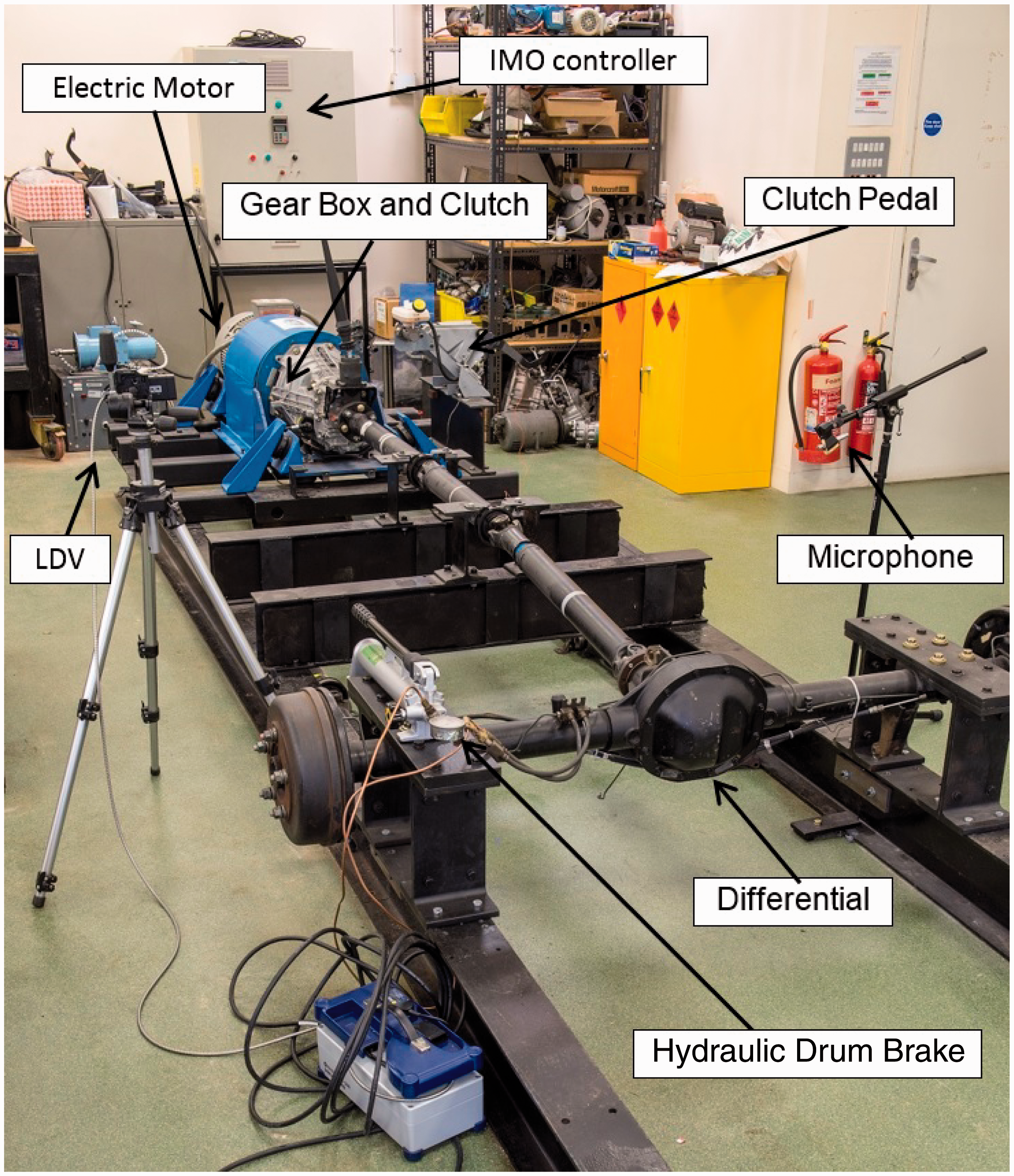
A series of experiments are carried out with the transmission engaged in second gear (ratio of 2.038:1) with an input torque of 145 Nm and input shaft speed of 1500 r/min. The inverter controller also inputs even order harmonics of the speed of 1500 r/min as would be the case for a 4-stroke 4-cylinder engine. 1 These conditions with sudden clutch engagement (pedal release) of less than 0.3 s have been noted to lead to severe clonk conditions in the vehicle’s field trials.
Two beam torsional Laser Doppler vibrometers (LDV) are placed along the driveshaft pieces (Figure 1) to record the passage of the propagating elastic wave through their structures. The beams separate the torsional oscillations of the tubes from their coupled bending response. This is essential as the high-frequency modal responses of the hollow driveshaft tubes are as a result of flexural modes due to their combined torsional-deflection responses. Free field microphones are also positioned on the opposing side of the driveshaft tubes to those of the vibrometers to capture the sound pressure level due to acoustic wave propagation (Figure 1). In this manner, simultaneous recording of vibration and noise can be made in order to ascertain the elasto-acoustic coupling responses of the structures. 8 The main difference between the current rig configuration and that reported by Gnanakumarr et al. 8 is the use of dual mass flywheel in the current study, which is now commonly used in nearly all vehicles as a palliative measure against transmission rattle. The use of a dual mass flywheel somewhat reduces the impulsive nature of the transient torque due to sudden release of the clutch pedal.
The employed instrumentation.
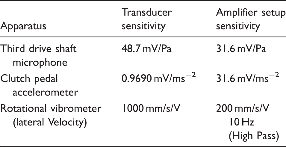
Nyquist criterion dictates a sampling rate of at least 10,000 in order to capture the higher clonk frequencies, which have been reported to occur up to a frequency of 5000 Hz. A conservative sampling rate of 32,000 sample/s is used. A repeatable experimental procedure is used with abrupt clutch pedal release of 100–300 ms, monitored by an accelerometer attached to the clutch pedal.
Numerical model
Flexible multi-body dynamics driveline model
A constrained flexible multi-body dynamics model is made of the flexible driveline system, comprising (1) impact dynamics of the transmission meshing gears under an impulsive input, induced by the sudden release of the clutch pedal; (2) flexible hollow driveshaft tubes and (3) the resistive (coasting) torque transmitted to the pinion gear from typical vehicle dynamic conditions. Figure 2 is a schematic representation of the driveline model, where the flexibility of the driveshaft tubes is taken into account through the use of finite element modal analysis and the inclusion of the modal responses into the overall multi-body model using component mode synthesis.
10
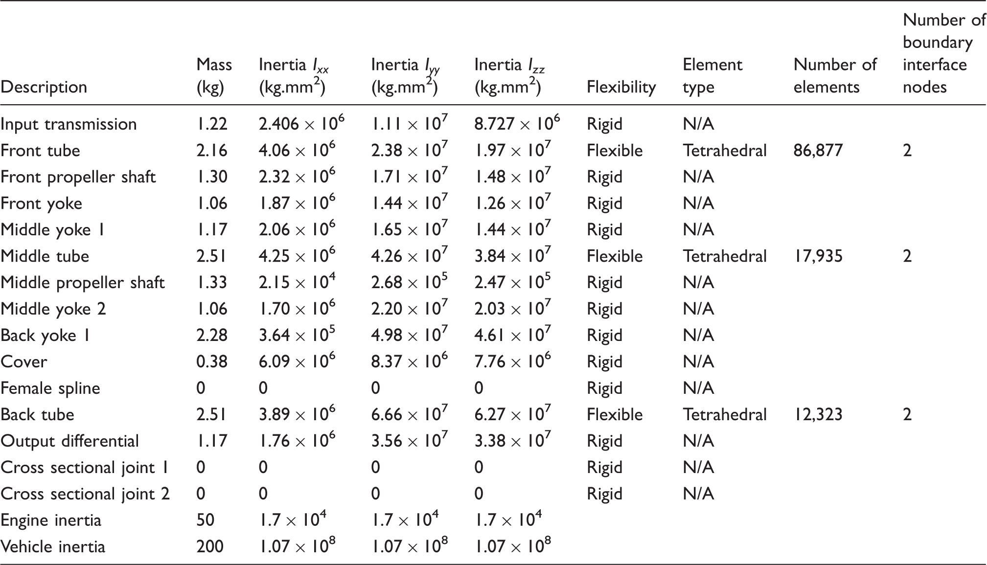
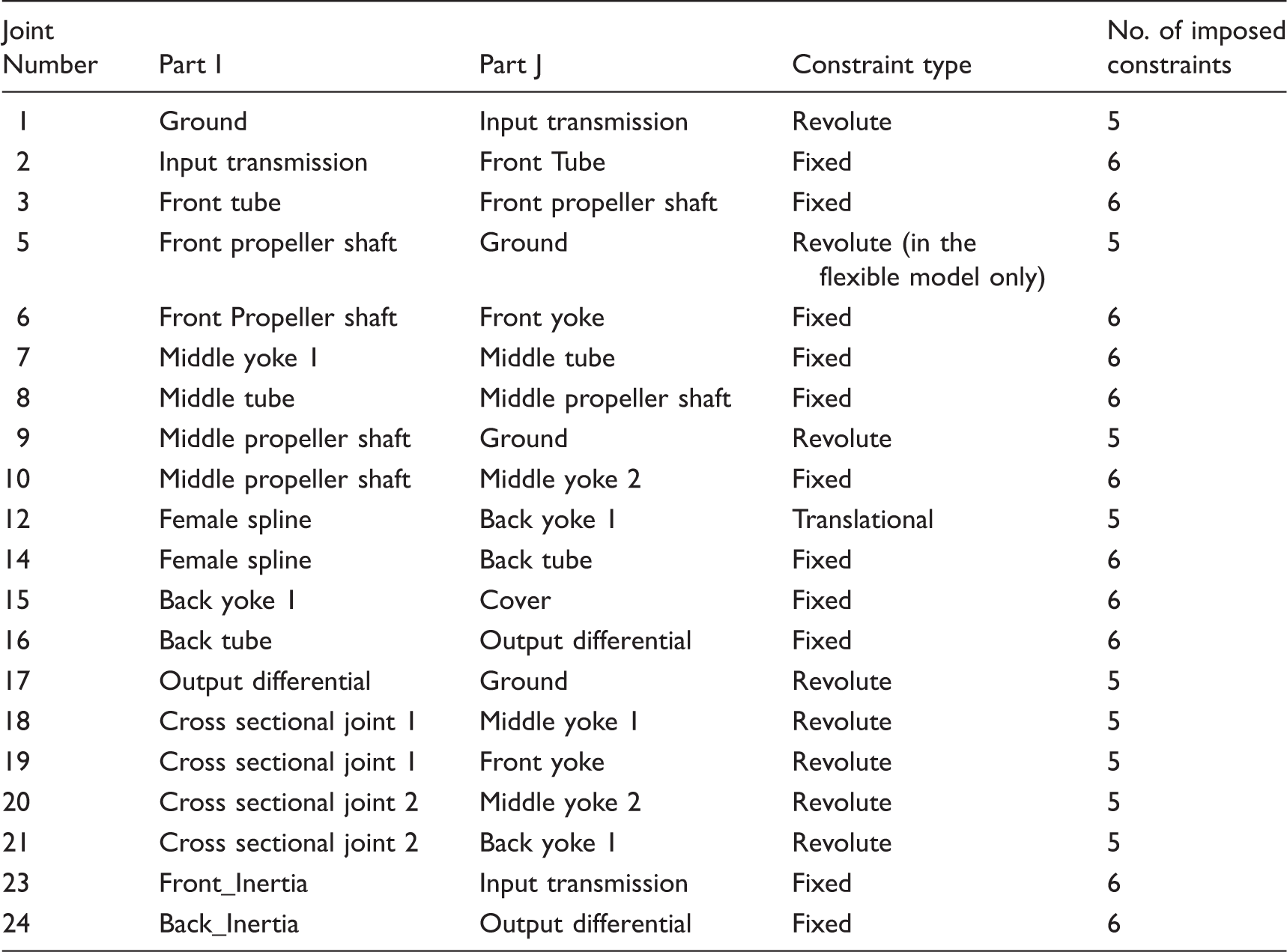
The parts used in the driveline model and their inertial properties are provided in Table 2. In this table, the type of element used to create the original flexible part, using finite element analysis is also noted. The flexible part includes interface nodes, known as a multi-point constraint; MPC which is then used to constrain the part to the multi-body assembly. The flexible part is represented by selected modal characteristics as described later by equation (4). Details of system constraints, as well as sources of compliances, restraints and external forces are provided in Tables 3 and 4.
Multi-body dynamics model of the driveline. Inertial properties of the driveline system. Constraint types representing assembly joints. Driveline restraints and compliances.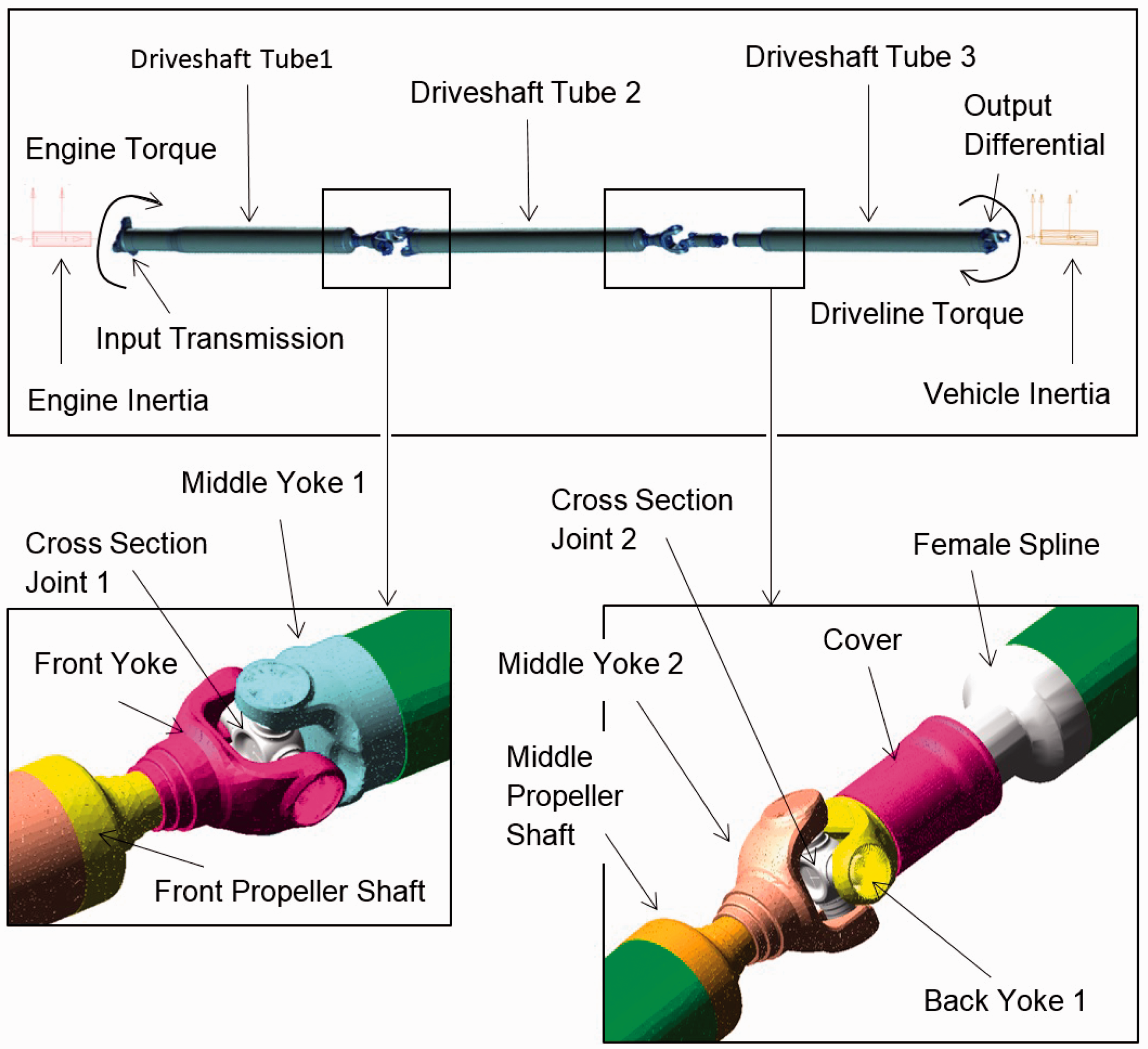
The number of degrees of freedom (DOFs), using the Chebychev–Gruebler–Kutzbach expression is
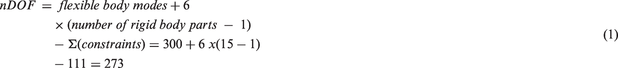
The governing equations of motion for the rigid and flexible bodies are derived from the Lagrange’s equation

The n constraint functions for the different joints in the driveline model are represented by a combination of holonomic and non-holonomic algebraic functions as

Equation (2) for all inertial components (the nominated parts in the system, listed in Table 2) and equation (3) for all the algebraic constraint functions, listed in Table 3 form a set of differential–algebraic equations which are solved together in suitably small steps of time. The solution vector
Representation of flexible bodies
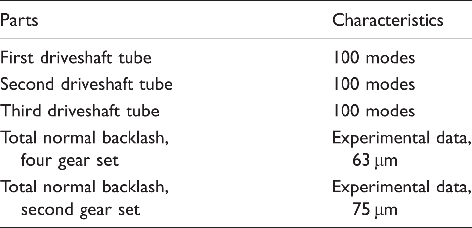
Hollow thin-walled driveshaft tubes are represented by their modal characteristics into the multi-body model. This approach improves the representative nature of the model with respect to the actual physical system and also improves the accuracy of its predictions.
In this approach, finite element discretisation of the flexible structures results in a very large number of DOFs, u, which can be approximated by a linear combination of a smaller number of shape vectors (or mode shapes), 
The main aim in modal superposition is to represent the very large number of modal DOF, in a predetermined frequency area, by a much reduced modal DOFs. The vector of modal coordinates and the modes
Applied forces
The applied forces 


Hence, the resultant resistive axle torque is

The input applied torque to the driveline system is as the result of the impact post abrupt release of the clutch pedal (the impulsive action), followed by the steady state engine torque transferred through the transmission system. The variation is shown in Figure 3. In its simplest form, the impact force may be represented by the classical Hertzian impact theory, where the kinetic energy of an equivalent mass, m impacting a solid surface with velocity v is converted to stored strain energy of deformation. In the case of an impacting meshing transmission teeth pair, the equivalent mass is that of the transmission input shaft with all the input pinion gears as well as the crankshaft–flywheel assembly. The impact velocity is the normal surface velocity of the pinion gear, gained through traversing the teeth-pair backlash.
The applied impact torque.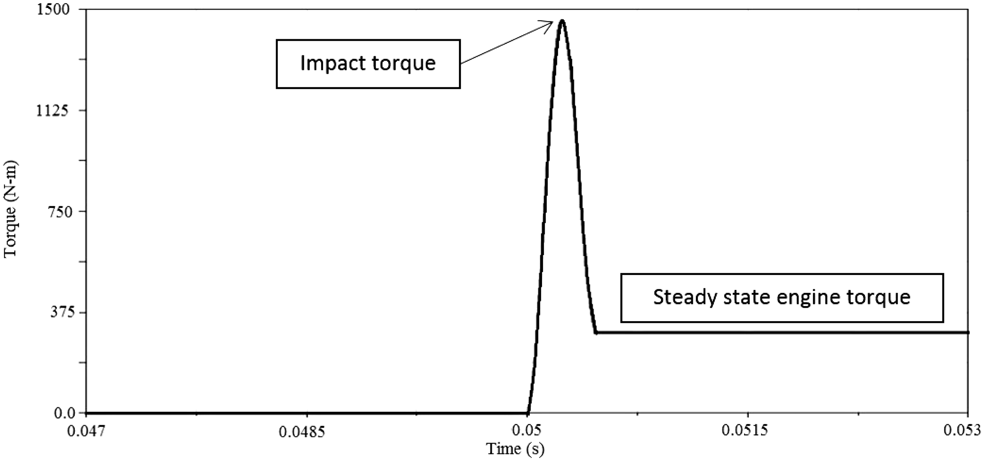
For the helical gear teeth pair, the instantaneous impact zone is an elliptical footprint. Using the Hertzian impact theory with no hysteretic losses leads to
15


The Hertzian theory represents the impact problem as that of an ellipsoidal solid of revolution impacting a semi-infinite elastic solid plane with an effective Young’s modulus of elasticity:
The ellipsoidal solid has two principal radii of contact as shown in Figure 4, depending on the radii of the meshing gear teeth in the corresponding planes of contact zx and zy.
16
Note that the classical Hertzian theory assumes localised small strain deformation of impacting solids with no change in their global geometry.
Impact of ellipsoidal solid with an elastic half-space.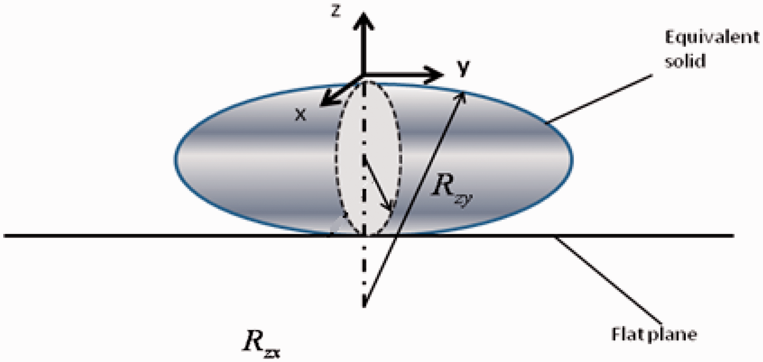
The impact load is then defined as

And, thus the torque on the driven transmission gear becomes

With the hurried release of the clutch pedal in a duration of 0.3 s (Figure 3), the hard initial impact torque magnitude is Successive clonk signals.
Results and discussion
Modal responses
Modal frequencies of the driveshaft (Hz).
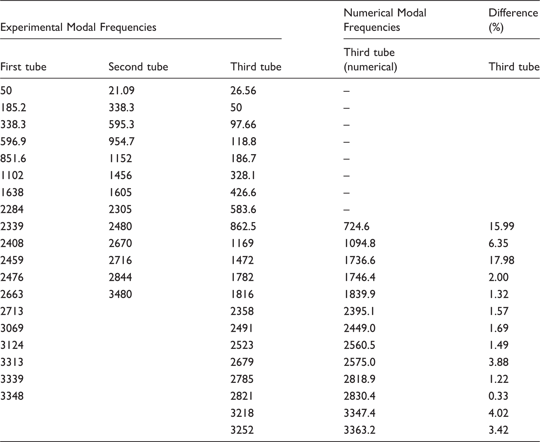
The first several relatively low-frequency modes of the tubes are pure bending or torsion. These modes couple at higher frequencies to create combined torsion–deflection modes known as the flexure modes. Some of these modes are the breathing modes, which are efficient noise radiators, such as the 1746 Hz response of the third driveshaft tube described later.
Experimental measurements of clonk tests
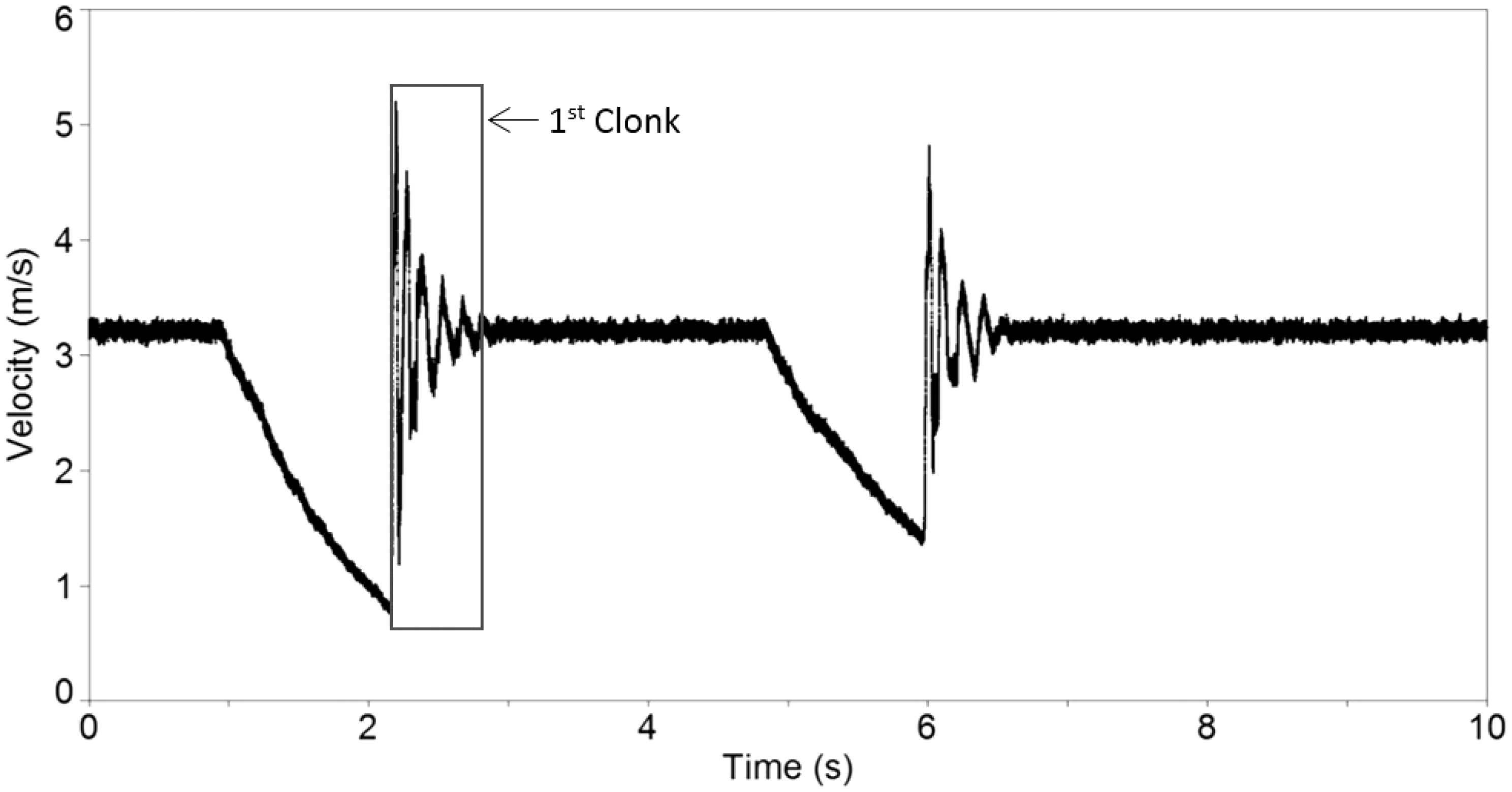
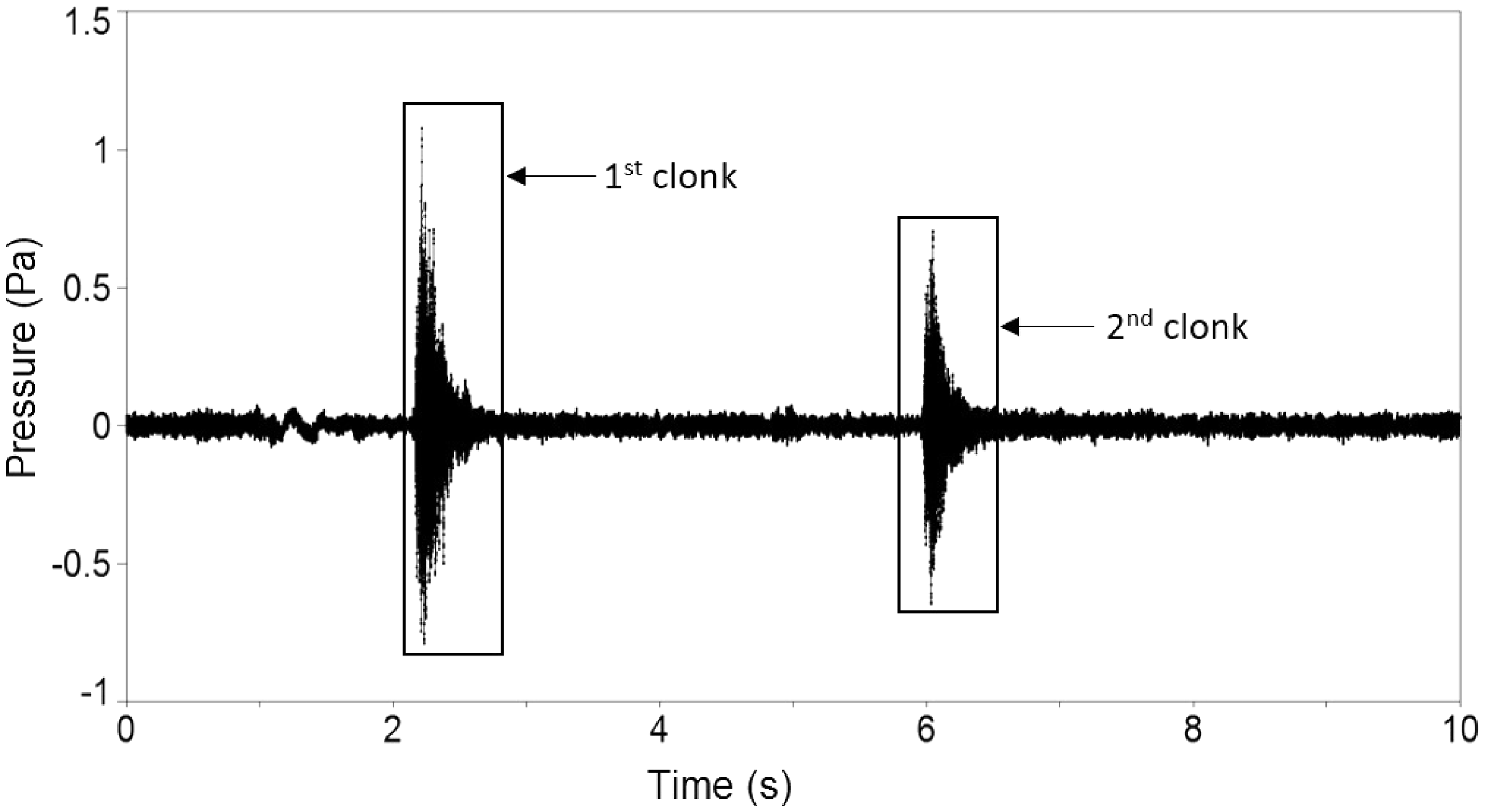
A series of clutch-induced clonk tests are carried out in line with the procedure highlighted in the Experimental Investigation section. Figure 5 displays the LDV measured experimental clonk signals. The figure shows two successive transient clonk events, measured by an LDV for a period of 10 s. The severity of the clonk (amplitude) is varied according to the clutch actuation rate.
A clonk event comprises a hard impact (impulsive event), followed by transient decay as can be seen in the Morlet wavelet spectrum of the measured structural surface velocity of Figure 6.
Measured spectral vibration response of the third driveshaft tube.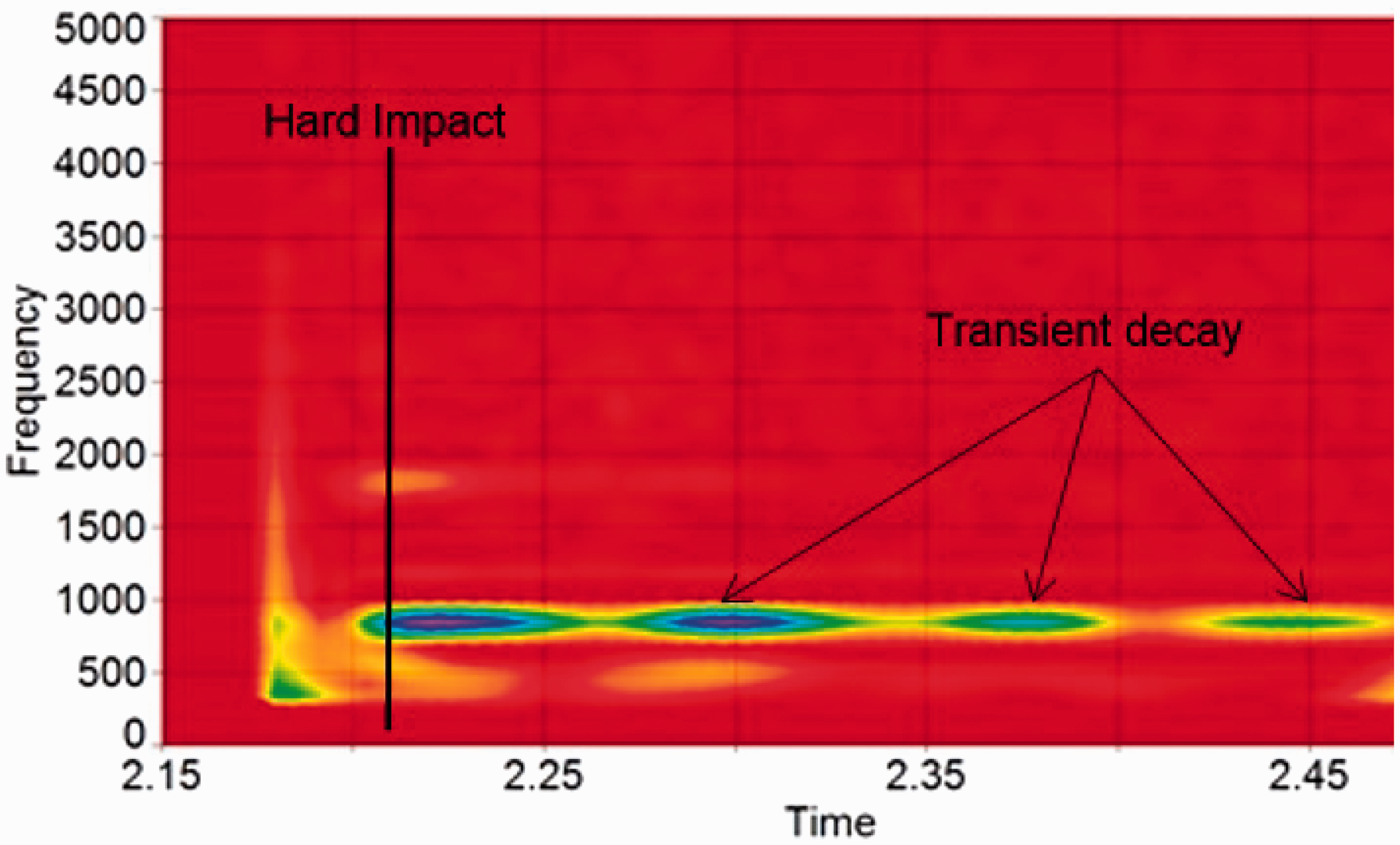
The hard impact leads to an accelerative type noise, which for solid structures would decay almost instantaneously. However, in the case of elastic hollow tubes, there is a period of decay marked by ringing-type acoustic response. Both types of acoustic wave are shown in the wavelet spectrum of sound pressure monitored by the free-field microphone in Figure 7. This spectrum corresponds to the first clonk event of the microphone signals for the two successive transient events in Figure 8.
Measured spectral sound pressure spectrum of the third driveshaft tube. Measured time history of successive clonk events.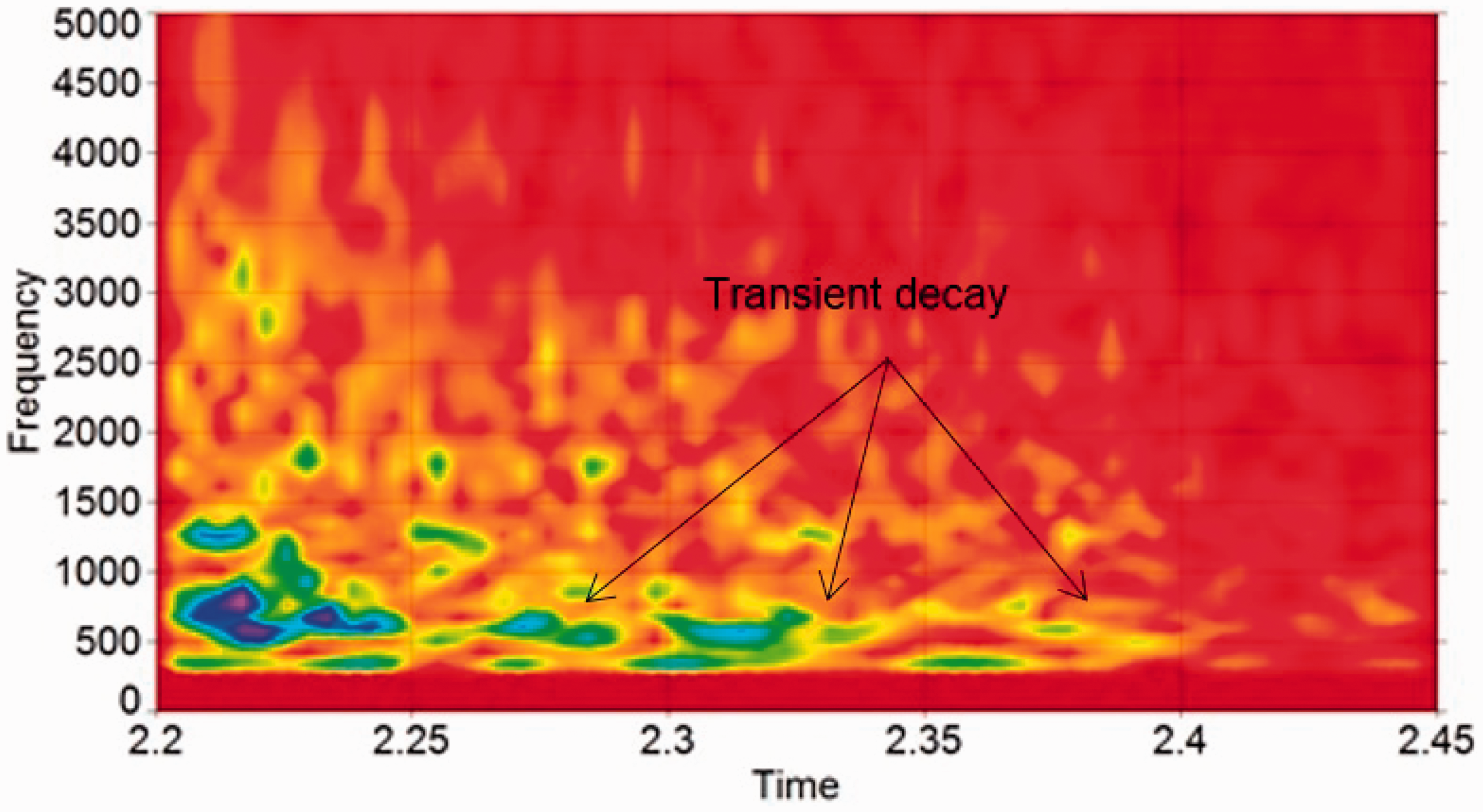
Figures 6 and 7 show broad-band responses during the hard impact event. The frequency content progressively reduces during the transient decay. In the case of noise spectrum (Figure 7), the transient decay corresponds to the ringing response. Some of the spectral content in the vibration and noise content coincide. This phenomenon is referred to as elasto-acoustic coupling. Some of these modal responses are efficient noise radiators and have high intensities. These are onomatopoeically referred to as clonk or clunk in industry and correspond to the structural modes of flexural nature, often referred to as the breathing modes. There are a multitude of such modes in the response of all the three hollow tubes of the driveline system. The examples of the modal responses of the third driveshaft tube in Figure 9 (∼700 and 1700 Hz) are obtained through finite element modal analysis, which have high intensity in the noise spectra of Figure 7, there are a multitude of such modes in the range ∼500–3500 Hz for the driveline system considered here.
Some breathing modes of the third driveshaft tube: (a) third tube breathing mode at 725 Hz and (b) third tube breathing mode at 1746 Hz.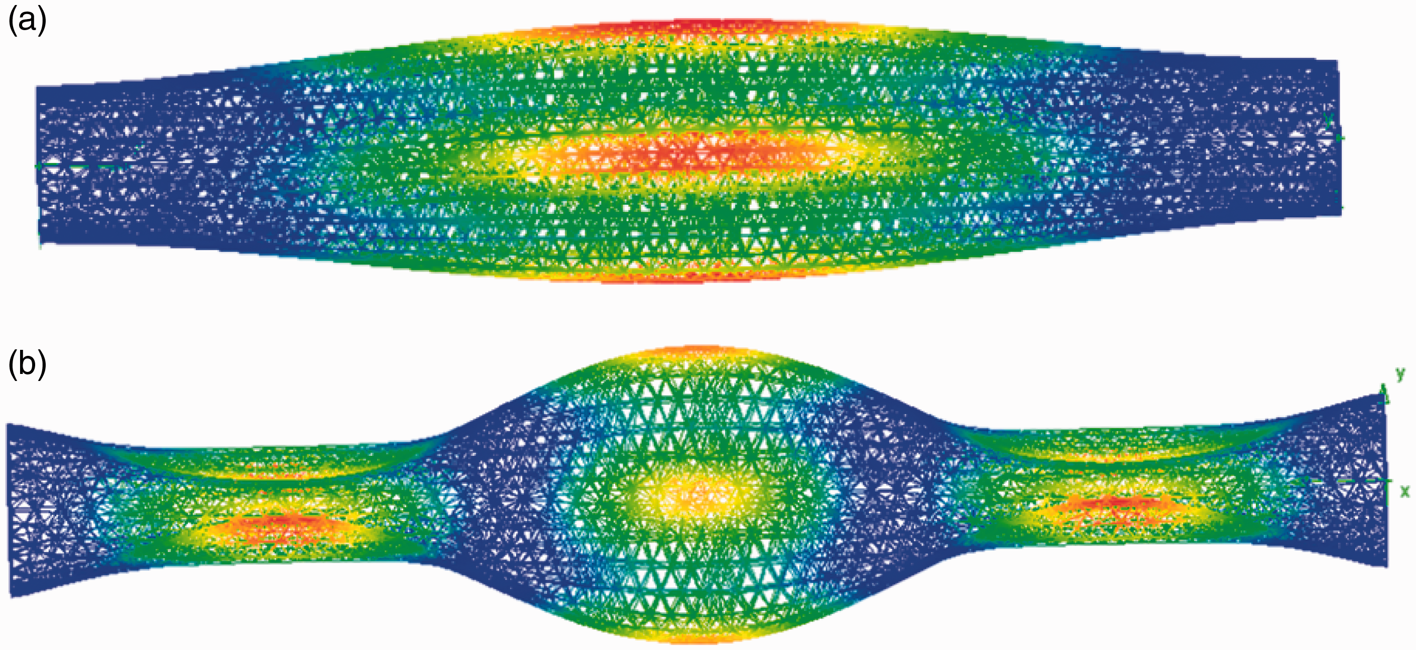
Numerical results
There are many parameters such as structural materials, geometry of driveshaft tube and other flexible components, assembly constraints, as well as operational parameters such as clutch actuation rate, gear selection and the vehicle weight (which affects the propensity to clonk). The multi-parameter nature of the problem makes the search for a broad palliative action quite difficult and calls for a very costly experimentation process. Consequently, development of a verified representative numerical model, such as the one reported here, for scenario building simulations is an essential requirement.
From a practical operational point of view, the clonk response of a commercial vehicle such as a light truck or a van depends on its laden state. Therefore, the numerical analyses carried out here are for three cases: (1) that of the experimental rig conditions for the purpose of validation of the numerical model, (2) for an unladen state of the vehicle and (3) for a half-laden state of the vehicle.
As the LDV measures the lateral oscillations of a structure, it is appropriate to determine the kinetic energy of the driveshaft tubes in the simulation studies, and use their spectral content as a form of numerical–experimental comparative study. The multi-body results can be compared with the measured results from the LDV. All simulations are performed for 0.3 s as for the monitored data in the experimentally monitored clonk signal (inset to Figure 5) with integration time step of 1 µs. The fine step size is required in order to capture all the fast transient events.
Figure 10 shows the predicted spectrum of response of the third driveshaft tube, corresponding to the experimental rig response of Figure 6. Due to the averaging nature of spectral analysis, a comparative study is carried out on the frequency content of the spectra rather than response amplitudes. Both the numerical and experimental spectra show broad-band frequency compositions in the range 500–4000 Hz with the initial hard impact event, followed by a transient decay response in the range ∼500–750 Hz. The numerical results also correspond to the modal response of the third driveshaft tube shown in Figure 9(a) as is the case for the LDV and microphone clonk responses as well.
Predicted vibration spectrum of the third tube kinetic energy for rig conditions.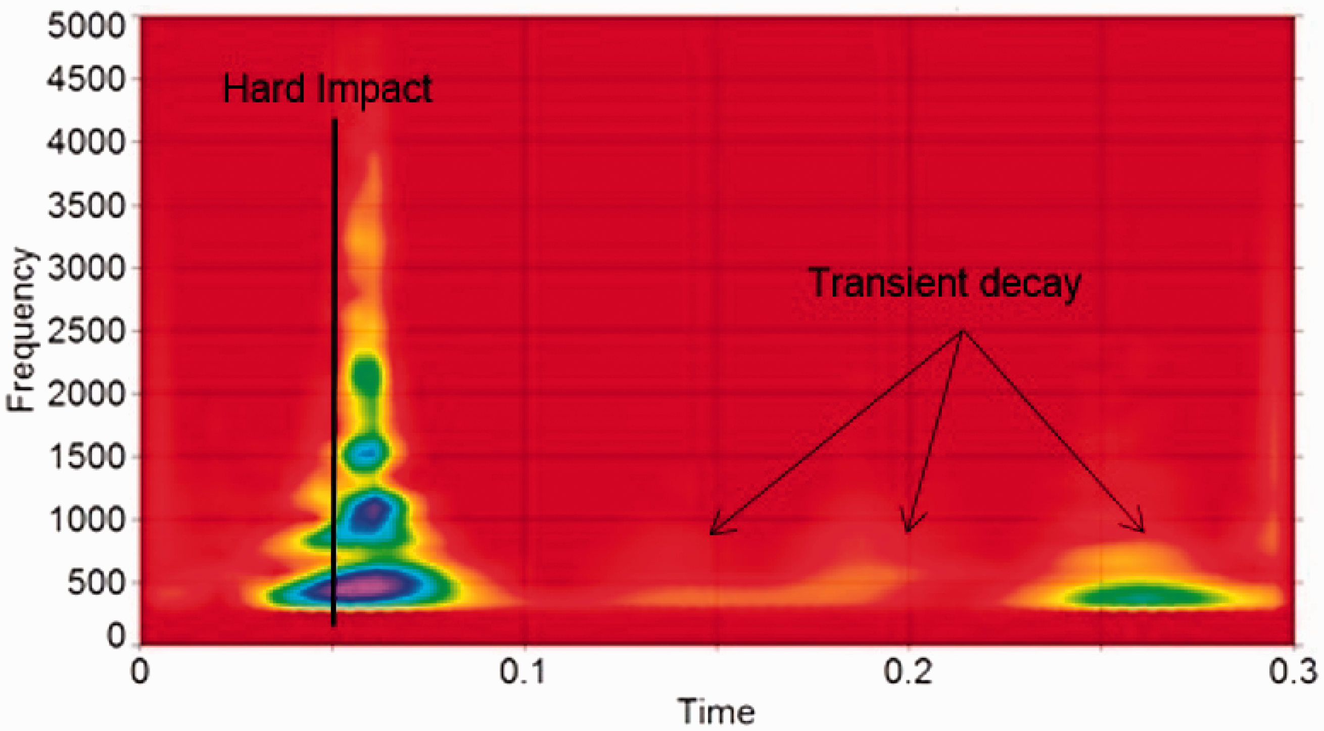
Effect of vehicle load
In vehicle conditions, throttle or clutch-induced clonk results in transient power flow in the drive-train system, usually accompanied by fore and aft motion of the vehicle, referred to as shunt. This action is coupled with torsional rigid body motion of the drive-train system, known as shuffle. These are the first fundamental rigid body modes of the drive-train system, usually in the range 3–10 Hz, depending on the vehicle inertia. Shunt of the vehicle is resisted by the stiffness of suspension mounts and axles, as well as by the rolling resistance at the tyre-road contact patch. Higher frequency response of the flexible parts in the driveline system, such as the hollow driveshaft tubes are superimposed upon the rigid body shuffle response. For in situ vehicle conditions, clonk can be more severe than that from the experimental rig because it is affected by the whole vehicle inertia. Therefore, the validated multi-body model is used to investigate the effect of vehicle laden condition on the propensity of the system to clonk.
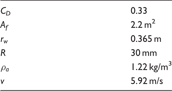
Simulation vehicle conditions.
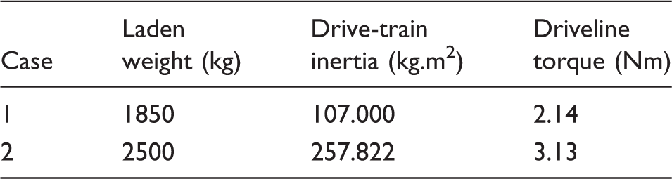
Additional input data.
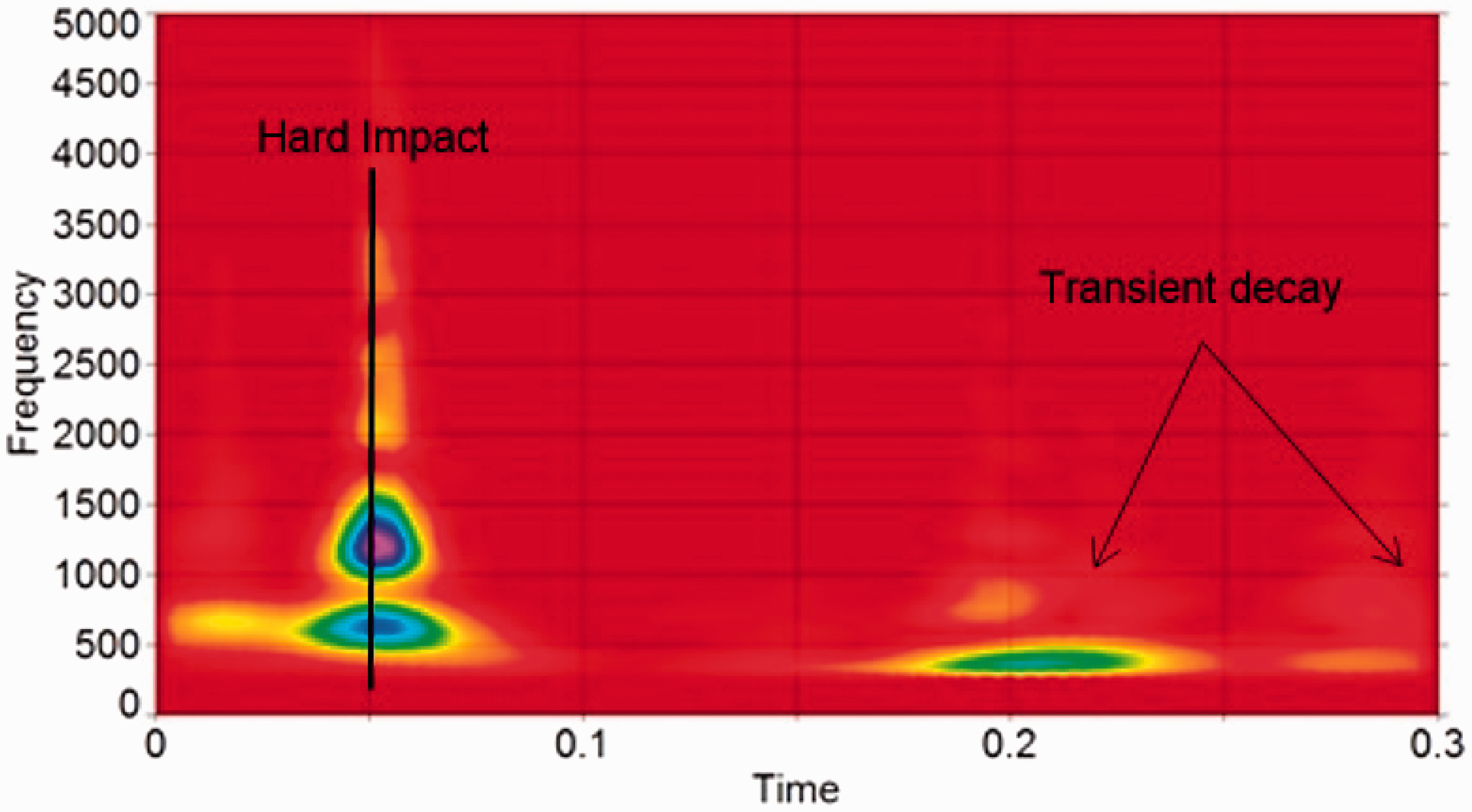
Figures 11 and 12 show the predicted spectral responses of the third driveshaft tube for the cases of unladen and partially laden vehicle under impulsive impact conditions. In both cases, as previously described for rig-based conditions, a hard impact occurs in the transmission zone of a broad-band nature (500 –4000 Hz). This is followed by transient decay of lower frequency content in regular intervals of approximately 0.05–0.1 s, corresponding to a carrier frequency. This period of oscillations corresponds to cycles of shuffle and shunt at a frequency of approximately 10–20 Hz. Therefore, as noted by Arrundale et al.,
5
cycles of shuffle are accompanied by a decaying clonk response, which is reduced in severity and frequency content with time. It can be seen that the initial hard impact clonk is broad-band (500–4000 Hz), which reduces in severity to spectral contents of mostly around 500–1500 Hz (in the case of the unladen vehicle, Figure 11) and 500–1000 Hz (in the case of partially laden vehicle, Figure 12). These lower frequencies create a ringing structure-borne response, because some of them are still of breathing nature such as the 725 Hz third tube response shown in Figure 9(a), thus efficient noise radiators. The cycles of shuffle are also reduced with the laden state of the vehicle as it would be expected of the higher inertial content. Therefore, the worst case for clonk conditions occurs with an unladen vehicle, as indeed noted in practice.
Third tube spectrum of kinetic energy in vehicle unladen condition. Third tube spectrum of kinetic energy in vehicle half-laden condition.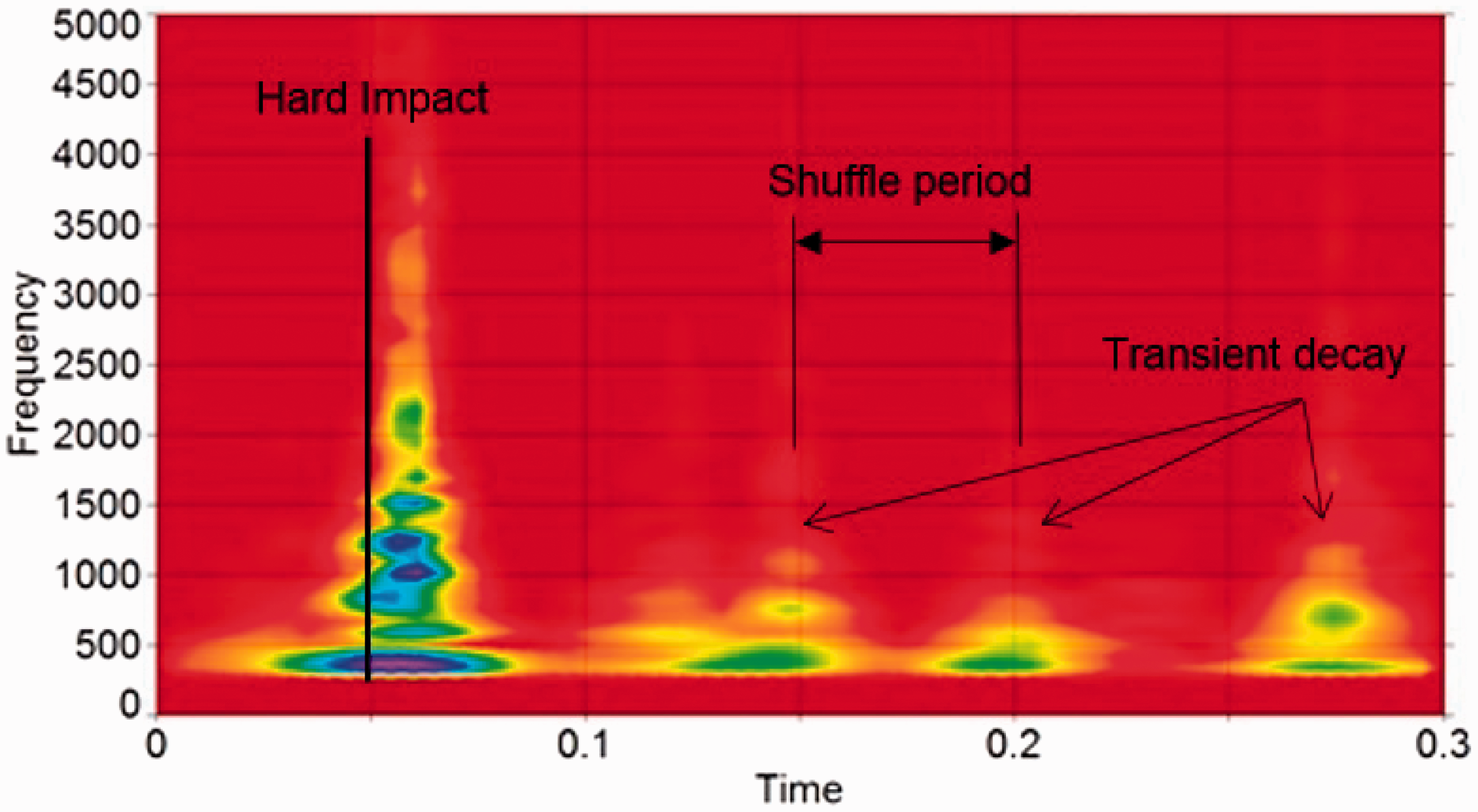
Conclusions
The experimental investigation of the clonk phenomenon using Laser Doppler Velocimetry (for measurement of vibration) and free-field microphones (for sound radiation) show broad-band response spectra from hollow driveshaft tubes, when the driveline is subjected to impulsive action through hurried release of the clutch pedal (clutch actuation).
The initial clonk response contains high-frequency breathing modes of short duration, which the human aural response is particularly attuned to. These are high-frequency breathing modes which are efficient noise radiators. The coincidence of vibration and acoustic modes are clearly shown.
A flexible multi-body dynamics model of the rig-based conditions includes clutch release duration and impact of meshing teeth pairs in the vehicle transmission. The predictions confirm the experimental findings of the spectral system response. The transient decay post the initial hard impact shows progressively reducing spectral content with lower frequencies, but still containing the lower breathing modes of the tubes, induced by cycles of shuffle with a ringing noise content.
The validated flexible multi-body dynamic model is used to investigate the effect of the laden state of the vehicle on its propensity to clonk. It is shown that the clonk response is more severe under vehicle conditions than that observed with the experimental rig, mainly due to the inertial effects in the fore-aft shunt of the vehicle. The predictions show that lower vehicle laden state (unladen in this case) has a longer shuffle response and increases the duration of the transient decay, corresponding to the ringing noise output.
In practice increasing the vehicle unladen mass is against the trend for fuel efficiency, therefore, this cannot be regarded as a design option. Nor reducing the longitudinal stiffness of the vehicle, mainly governed by the contact patch stiffness (the lowest stiffness axial component) would be a suitable option as this would adversely affect the vehicle tractive power due to slip. Hence, palliation is sought in situ for the hollow driveshaft tubes as highlighted by Gnanakumarr et al. 17
Footnotes
Acknowledgements
The authors would like to acknowledge the Engineering and Sciences Research Council (EPSRC), Vehicle Foresight Directorate, Ford and MSC Software for their original support of the research project OPTRAREF.
Declaration of Conflicting Interests
The author(s) declared no potential conflicts of interest with respect to the research, authorship, and/or publication of this article.
Funding
The author(s) disclosed receipt of the following financial support for the research, authorship, and/or publication of this article: Engineering and Physical Sciences Research Council 10.13039/501100000266 Ford Motor Company 10.13039/100002427.