
Abstract
This study presents two complementary computational approaches for optimizing the natural frequencies of laminated composite plates with cutouts. The first approach employs Particle Swarm Optimization (PSO) to explore a combined design space including ply angles, hole center location (xc, yc), and hole radius R for laminated composite plates with circular cutouts. Ply orientations are treated as continuous variables within [−90∘,90∘] and rounded to integer values, while geometric constraints ensure that the cutout remains within the plate boundaries. The second approach introduces a finite-element pre-processing technique, termed Adjacent Element Temperature Driven Prestress (AETDP), which constructs a temperature-induced prestress field directly from the mesh adjacency graph using a breadth-first search algorithm. This enables efficient prestressed modal analysis without coupled thermo-mechanical simulations. Validation against numerical and experimental benchmarks shows mean absolute errors below 8%. Optimization results indicate that optimal cutout locations tend to align with modal nodal lines, reducing stiffness loss, while highly constrained plates tolerate larger cutouts. The AETDP approach reduces computational time significantly compared with full PSO optimization.
Keywords
1. Introduction
Glass and carbon fiber-reinforced polymer composites have become indispensable materials in modern aerospace, marine, automotive, and civil infrastructure industries due to their superior specific strength, stiffness-to-weight ratios, and design versatility. 1 These advanced materials allow for significant weight reduction while maintaining or enhancing structural performance, making them ideal for applications where efficiency and reliability are paramount. Planar composite structures, particularly plates and shells, form critical components in these sectors. However, functional requirements often necessitate the inclusion of discontinuities or cutouts within these structures for purposes such as mechanical access, weight reduction, utility routing, and inspection ports.2,3 While essential, the introduction of these geometric discontinuities fundamentally alters the structural mechanics, leading to complex stress concentrations, redistributions of stiffness and mass, and significant modifications to the dynamic vibrational response.4,5 These alterations can shift the system’s natural frequencies, potentially bringing them into resonance with operational excitation frequencies, thereby increasing the risk of accelerated fatigue damage, reduced service life, and catastrophic failure. 6
Consequently, optimizing the dynamic performance of perforated composite plates emerges as a critical and multifaceted design challenge. A primary objective in such optimization is often the maximization of the fundamental natural frequency to avoid resonance, thereby enhancing operational safety and structural integrity.7,8 This optimization problem is inherently high-dimensional and complex, involving the simultaneous consideration of numerous interdependent design variables. Key parameters include the laminate’s stacking sequence (i.e., the specific fiber orientation angles in each ply), the overall laminate thickness, and the precise geometry of the cutout—encompassing its size, shape, and location within the plate.9,10 Traditional design approaches, which often rely on engineering intuition and iterative physical or computational testing, are ill-suited to efficiently navigate this vast and non-linear design space where optimal configurations frequently defy conventional expectations.
This study addresses this challenge by developing and presenting a comprehensive, integrated computational framework for optimizing the natural frequencies of rectangular composite plates containing a circular cutout. The framework leverages the accuracy of the Finite Element Method (FEM) for conducting detailed modal analyses. The validity and precision of the FEM model are rigorously established through comparison with established numerical and experimental benchmark data from the literature. To navigate the complex optimization landscape, a Particle Swarm Optimization (PSO) algorithm is employed. This metaheuristic optimizer is tasked with identifying the global optimum combination of design variables: the laminate stacking sequence and the cutout’s geometric parameters, specifically its center coordinates and radius. The investigation is comprehensive, analyzing plates with multiple aspect ratios under four distinct boundary conditions to generalize the findings. The results demonstrate the efficacy of the proposed FEM-PSO framework and reveal that optimal designs for vibrational performance often involve non-intuitive placements and sizes of cutouts. This underscores the necessity and value of employing systematic, computational optimization in the design phase of lightweight, perforated composite structures to unlock their full performance potential.
The dynamic analysis, characterization, and optimization of laminated composite plates—especially those incorporating cutouts—represent a rich and extensively researched field within structural mechanics and materials engineering. The body of literature is vast, evolving from fundamental analytical studies to sophisticated numerical simulations coupled with advanced optimization algorithms. This review synthesizes the existing knowledge by categorizing the research into several interconnected thematic areas.
1.1. Free vibration analysis of composite plates
The foundational understanding of vibrational behavior in composite laminates stems from extensive analytical and numerical investigations. Early pioneering work established robust analytical methods, such as the Rayleigh-Ritz technique employing orthogonal polynomials, which provided accurate solutions for the natural frequencies of symmetrically laminated plates under a variety of classical boundary conditions.11,12 The development and adoption of shear deformation theories, most notably the First-order Shear Deformation Theory (FSDT), became crucial for the accurate analysis of moderately thick plates, where transverse shear effects are significant. 13 As structural geometries and boundary conditions grew more complex, numerical methods—particularly the Finite Element Method (FEM)—rose to prominence as the standard computational tool. A multitude of studies have successfully utilized FEM to systematically investigate the influence of plate geometry (aspect ratio, thickness), material anisotropy, and support conditions on natural frequencies and mode shapes.2,14 In recent years, the field has seen significant advances with the introduction of Isogeometric Analysis (IGA), which offers superior geometric exactness and smoother modeling for structures with complex shapes or cutouts.15,16 Furthermore, research continues into refined higher-order theories and the analysis of novel material systems, such as three-phase composites reinforced with graphene platelets and carbon fibers, to achieve even more accurate predictions of dynamic response. 17
1.2. Effects of cutouts on vibration characteristics
The introduction of a cutout creates a discontinuity that dramatically alters a plate’s stiffness and mass distribution, leading to a complex modification of its dynamic signature. A consistent finding across the literature is that cutouts generally reduce natural frequencies, although the magnitude and nature of this effect are governed by several interacting factors. Cutout shape is a primary determinant; comparative studies of circular, square, elliptical, diamond, and skew-shaped openings reveal distinct differences in stress concentration factors and the consequent reduction in fundamental frequency.18–20 The size and location of the cutout are equally critical. Typically, increasing cutout size reduces global stiffness and lowers the fundamental frequency, but this relationship is non-linear and can even be inverse for specific boundary conditions, such as cantilever supports.18,21 The location of the cutout relative to the nodal lines of the vibration modes profoundly influences the dynamic response, as cutting through a high-strain area has a more detrimental effect than removing material from a low-strain region. 3 Finally, the interaction between boundary conditions and laminate parameters mediates the overall effect. The same cutout will impact a clamped plate differently than a simply supported one. Moreover, the fiber orientation angles and the stacking sequence of the laminate dictate its anisotropic stiffness, which in turn influences how the structure redistributes loads and strains around the discontinuity.13,22
1.3. Optimization of composite laminates
Driven by the need for high-performance, lightweight structures, the optimization of composite laminates has become a major research focus. The goal is to find the best possible laminate configuration to maximize a desired performance metric, such as natural frequency or buckling load, often under constraints like weight or strength. The primary design variables are the fiber orientation angles in each ply and the resulting stacking sequence. Seminal work in this area focuses on optimizing these variables for fundamental frequency maximization23,24 or buckling resistance. 25 Given the discrete, non-convex, and often multi-modal nature of the design space, traditional gradient-based optimizers are frequently inadequate. Consequently, heuristic and metaheuristic optimization algorithms have become the tools of choice. Genetic Algorithms (GA) have been widely and successfully applied for stacking sequence optimization across various plate and shell geometries.26–28 Similarly, Particle Swarm Optimization (PSO) has demonstrated excellent performance and robustness in solving structural optimization problems, often outperforming other methods in terms of solution quality and convergence speed.29–32 The algorithmic toolbox is diverse, also including Simulated Annealing (SA),6,33 Harmony Search, 9 the Bonobo Optimizer, 10 Bayesian Optimization, 7 and pattern search methods. 34 Research in this domain has expanded into advanced optimization topics, including multi-objective formulations that trade off weight savings against frequency or buckling load maximization, 35 stochastic optimization to account for material and fabrication uncertainties,36,37 and topology optimization for generating novel, high-performance conceptual designs.38–40 A parallel and critical strand of research focuses on durability optimization, specifically designing laminates for maximum fatigue life under cyclic loading conditions.6,41–44
1.4. Optimization of plates with cutouts
The presence of a cutout adds a layer of geometric variables to the optimization problem, significantly increasing its complexity. Research here can be subdivided. Stacking sequence optimization for plates with predefined cutouts involves finding the best ply angles to mitigate stress concentrations and maximize performance metrics like buckling load or fundamental frequency for a given hole geometry.8,9,34 A revolutionary design paradigm is enabled by Variable Stiffness Composites (VSC) or Variable Angle Tow (VAT) laminates. Here, curvilinear fiber paths allow the material stiffness to be spatially tailored to redirect load paths around the cutout, leading to remarkable improvements in load-bearing capacity, buckling performance, and vibrational characteristics.45–49 The optimization of these curvilinear fiber paths is itself an active research frontier.27,28,50 Despite these advances, studies that perform simultaneous optimization of both the laminate stacking sequence and the cutout’s geometric parameters (size, location) for dynamic performance remain relatively scarce. This integrated approach, which is the core focus of the present study, represents a more holistic and powerful design strategy but poses greater computational and methodological challenges.
1.5. Related advanced topics
Structured overview of the review.

1.6. Research gap and contribution
1.6.1. Research gap
The majority of recent studies on perforated composite plates treat the laminate configuration and the cut-out geometry as independent design problems. Work on stacking-sequence optimisation typically assumes a solid plate, while investigations on cut-out optimisation usually neglect the influence of the laminate lay-up and of any residual or thermal stresses. When prestress effects are considered, they are introduced through a full transient heat-transfer analysis, which dramatically increases the computational load and makes the problem intractable for meta-heuristic searches. Moreover, most published optimisation frameworks do not provide quantitative validation against experimental data or assess the robustness of the found designs. Consequently, a unified, computationally efficient methodology that simultaneously optimises laminate stacking, cut-out size and location, and accounts for prestress effects is still missing.
1.6.2. Contribution of the present study
This work introduces a
The main contributions are: • • • • •
By integrating a fast, physics-based prestress generator with a robust global optimiser, the present study delivers a reproducible workflow for the vibration-sensitive design of laminated composite plates with perforations, while honestly presenting the capabilities and limitations of the proposed approach.
2. Materials & methods
The present work couples a high-fidelity finite-element (FE) model of a laminated composite plate with a particle-swarm optimisation (PSO) algorithm that searches simultaneously for the optimum stacking sequence and the optimum circular cut-out geometry. The entire procedure – from material definition to validation – is described in the following paragraphs so that the study can be reproduced without ambiguity.
2.1. Composite laminate definition
A four-ply laminate is considered, built from carbon-epoxy orthotropic lamina. The total laminate thickness is 0.04 m, giving a ply thickness of t{p} = 0.01 m. The stacking sequence is represented by the decision vector
The lamina stiffness matrix in the principal coordinates,
Manufacturing considerations: In practical composite manufacturing, laminates are often designed with balance
2.2. Plate geometry and cut-out
The optimization procedure was carried out for three different geometric configurations by varying the aspect ratio, specifically a/b=1, a/b=0.5 and a/b=0.3333.
To explain the geometry and the cut-out strategy, the case
The plate occupies the rectangular domain
A circular cut-out of radius 

These limits ensure that the cut-out is at least 5 mm from any side and that it never contains more than 30 % of the plate area.
2.3. Finite-element modelling
The laminate is discretised with a 4-th-order isoparametric shell element (ANSYS SOLSH190). The element formulation inherently incorporates higher-order shear deformation and thereby avoids shear-locking. A structured mesh is used with uniform element size
2.3.1. Boundary conditions
A combination of free (F) and clamped (C) edge boundary conditions were applied to different edges of the plate in various simulation scenarios. An example of the boundary condition selection for aspect ratio 0.333 is explained below. • • •
The circular cut-out is modeled by a
2.4. Eigenvalue extraction
A direct modal analysis is used to extract the first ten natural frequencies. The ANSYS directives are: ANTYPE,2 !direct modal analysis MODOPT,LANB,10 !first 10 eigen-modes EIGAMIP !high-accuracy eigenvalue solver The computed frequencies are denoted
2.5. Formulation of the optimisation problem
The optimisation objective is constructed as a penalised natural frequency:

The plus–operator
2.6. Particle-Swarm Optimisation (PSO)
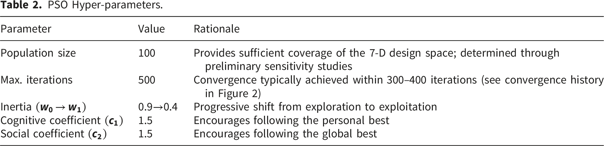
The Particle Swarm Optimization (PSO) algorithm was selected as the primary optimization method for this study based on its demonstrated performance in prior benchmarking efforts. As systematically documented in our previous work, 29 which provided a comprehensive comparison of SA, GA, and PSO on similar composite laminate optimization problems, PSO exhibited superior convergence speed and solution quality. A full-scale, three-way comparative analysis (PSO vs. GA vs. SA) for the specific problem defined herein, while undeniably valuable, would increase the total computational cost by approximately threefold. Such an extensive benchmark, though reserved for future work, is not the central aim of the current investigation, which focuses on the novel application of optimization to the specific multi-objective problem of buckling and vibration.
PSO Hyper-parameters.
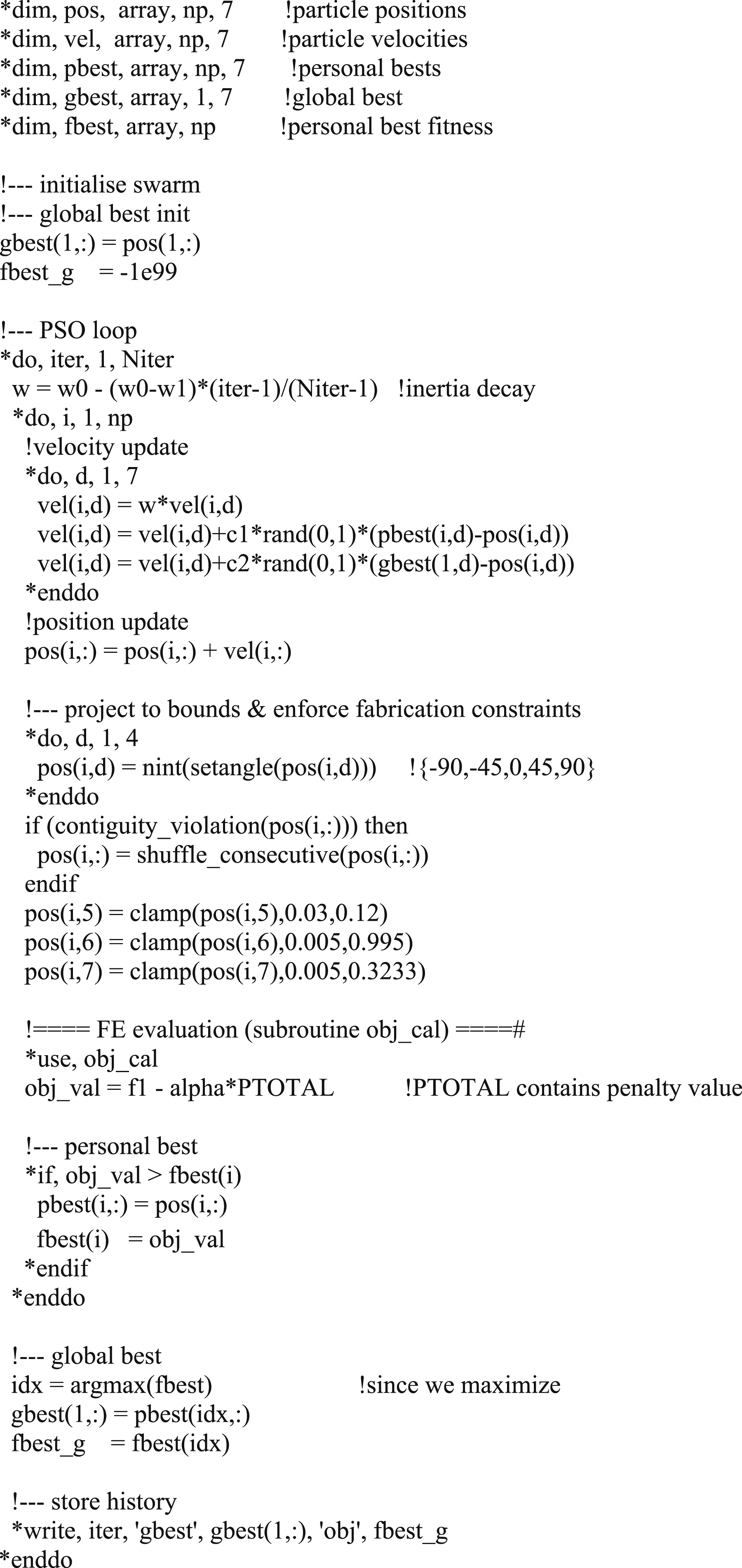
Algorithm 1:
2.6.1. Convergence behavior
The evolution of the global best objective value over 500 iterations for a representative case (CCCC, a/b=1), the objective stabilizes after approximately 350 iterations, indicating that the chosen maximum iteration count is sufficient. Each iteration requires 100 FE evaluations (one per particle), giving a total of 50,000 FE analyses per optimization run. On a workstation with a complete PSO optimization (500 iterations × 100 particles) requires approximately 8 days of CPU time. This computational cost motivates the development of the more efficient AETD-P-based angle-only optimization described in Section 2.7.
2.6.2. Parameter selection rationale
The population size of 100 was chosen based on preliminary runs showing that smaller populations (e.g., 50) occasionally converged to local optima, while larger populations (>150) yielded diminishing returns in solution quality. The inertia decay from 0.9 to 0.4 follows standard PSO practice, providing initial global exploration followed by local refinement. Cognitive and social coefficients of 1.8 maintain a balance between individual and collective learning.
2.6.3. Note on implementation
The APDL code includes safety checks to prevent invalid geometries (e.g., cutouts intersecting plate boundaries) and applies penalty functions as described in Section 2.5. The rounding of ply angles to nearest integer degrees occurs after the PSO update, ensuring that the optimizer works with continuous values during the search while producing physically realizable angles in the final output.
2.7. Adjacent Element Temperature Driven Prestress (AETDP) – A pure-FE pre-processor
The Adjacent Element Temperature Driven Prestress (AETDP) algorithm is a stand-alone finite-element pre-processor that creates a temperature-induced prestress field without invoking any heat-transfer simulation. Its workflow is completely deterministic: the temperature distribution is generated solely from the geometric and topological information of the mesh, and the resulting field is then fed to the structural solver for a prestressed modal analysis.
2.7.1. Algorithm description
The steps are: 1. Mesh creation – a three-dimensional hexahedral (C3D8) discretisation of the plate is built. The cut-out is extruded through the full thickness by simply removing the elements whose centroids fall inside the prescribed circle. 2. Adjacency graph construction – each element’s six faces are identified, and an undirected adjacency list is assembled (two elements are neighbours when they share a complete face). 3. Breadth-first-search (BFS) distance field – a user-specified seed element (or a set of seeds) initiates a BFS that assigns to every element e an integer graph distance dist [e] equal to the number of face-to-face hops from the nearest seed. 4. Casting-factor evaluation – for each element the volume 5. Temperature assignment – a linear temperature drop is imposed over the BFS layers, and the casting factor is used to modulate the drop according to 6. Nodal averaging – the element temperatures are averaged onto the incident nodes, producing a nodal temperature dictionary nodalT. 7. Prestressed modal analysis – the nodal temperature field is introduced into the ANSYS/CalculiX input file via a single *TEMPERATURE block; the modal command is patched with PRESTRESS=YES. When the solver runs, the stiffness matrix automatically incorporates the geometric-stiffness contribution generated by the temperature field, and the eigenvalues obtained correspond to the prestressed natural frequencies of the structure.

2.7.2. Calibration of temperature parameters
The temperature parameters used throughout this study were calibrated from a single experimental reference case to ensure physically realistic prestress magnitudes. The reference case is the 0° fiber orientation, W-C (clamped-free) boundary condition specimen from Ref. 19, which provided experimental modal frequencies for a perforated composite plate.
The calibration procedure was as follows: 1. The experimental fundamental frequency (40 Hz for the reference case) was taken as the target. 2. A series of AETD-P analyses were performed with varying Tmax, Tmin, and Vd, while keeping the BFS seed element fixed at the clamped edge (seed element 1). 3. The parameters that produced a prestressed fundamental frequency matching the experimental value were selected: o Tmin = 22.8 C0 (ambient temperature) o Tmax = 120.3 C0 (elevated temperature representing curing or operational thermal load) o Vd = 1.7 x10⁻⁴ (drop coefficient controlling the influence of element geometry)
These calibrated values were then
2.7.3. Physical interpretation
The temperature field generated by AETDP should not be interpreted as a literal thermal load from a specific physical process. Instead, it serves as a • Physically plausible (calibrated to experimental data) • Computationally efficient (generated in seconds without solving heat transfer equations) • Topologically informed (based on mesh adjacency, so prestress propagates naturally through the structure)
The resulting prestress stiffens the plate in a manner analogous to residual stresses from manufacturing (e.g., differential cooling after autoclave curing) or in-service thermal gradients. By incorporating this effect, the AETDP method provides a more realistic assessment of dynamic performance than purely elastic analyses, while avoiding the computational burden of coupled thermal-structural simulations.
2.7.4. Computational efficiency
Because the entire procedure involves only mesh operations, BFS traversal, and elementary algebraic formulas, it is extremely fast. For a plate with several thousand elements, temperature field generation completes in 2–3 seconds on a standard workstation. A complete AETD-P-augmented modal analysis (including mesh generation, temperature assignment, and CalculiX solve) typically requires 30–60 seconds, making it suitable for integration into optimization loops.
2.8. Reference studies-based validation
As an application of the proposed optimization framework, a square composite laminate containing a circular cutout, as illustrated in Figure 1, is considered. The optimization problem is formulated by defining the hole center coordinates, the hole radius and the laminate stacking sequence as design variables. The radius of the circular cutout is constrained within prescribed upper and lower bounds, which are specified in the results section to ensure structural feasibility. Depending on the imposed boundary conditions, the allowable variation of the hole location, its radius, and the stacking sequence gives rise to a wide and highly nonlinear feasible design space. The interaction between geometric parameters, material anisotropy, and boundary constraints leads to complex changes in the dynamic response of the laminate. As a result, the influence of each design variable on the fundamental natural frequency cannot be accurately captured through conventional parametric or trial-and-error approaches. Within this multidimensional solution domain, identifying the optimal combination of hole size, hole location, and laminate configuration that maximizes the fundamental natural frequency becomes a challenging task. This complexity highlights the necessity of employing a systematic and robust optimization strategy rather than relying solely on intuitive design rules or limited parametric studies. Boundary conditions arranged in counterclockwise direction (C: clamped, F: free).
2.9. Validation of the numerical model
To assess the accuracy of the finite element (FE) analysis results for natural frequencies, a comparative validation study was performed by contrasting the findings of the present work with those reported in the literature.11,12,19,33 Two validation stages were conducted: (i) comparison with numerical benchmark solutions for plates without cutouts, and (ii) comparison with experimental results for plates with and without circular cutouts.
2.9.1. Material properties

2.9.2. Numerical validation (plates without cutouts)
Comparison of the present study with numerical results from literature.


The present FEM results show good agreement with all three reference studies, with percentage errors ranging from -3.51% to +4.28% across the first six modes. The largest discrepancy occurs for Mode 5 (-3.51% vs. Ref. 33), while Modes 2-4 show errors below 2.2%. These differences are attributed to variations in element formulation (SOLSH190 vs. analytical/semi-analytical methods in the references) and mesh density. The mean absolute error across all modes is 2.48%, confirming the reliability of the FE model for subsequent optimization studies. The AETDPA results (which include prestress) show systematically different frequency distributions, as expected. The prestress effect reduces the fundamental frequency (8.78 Hz vs. 11.94 Hz) while altering higher mode spacing—a consequence of the temperature-induced geometric stiffness. This comparison highlights that AETDPA produces physically distinct results from elastic analysis, which is the intended behavior.
2.9.3. Experimental validation (plates with cutouts)
Comparison of the present study with experimental results from literature.

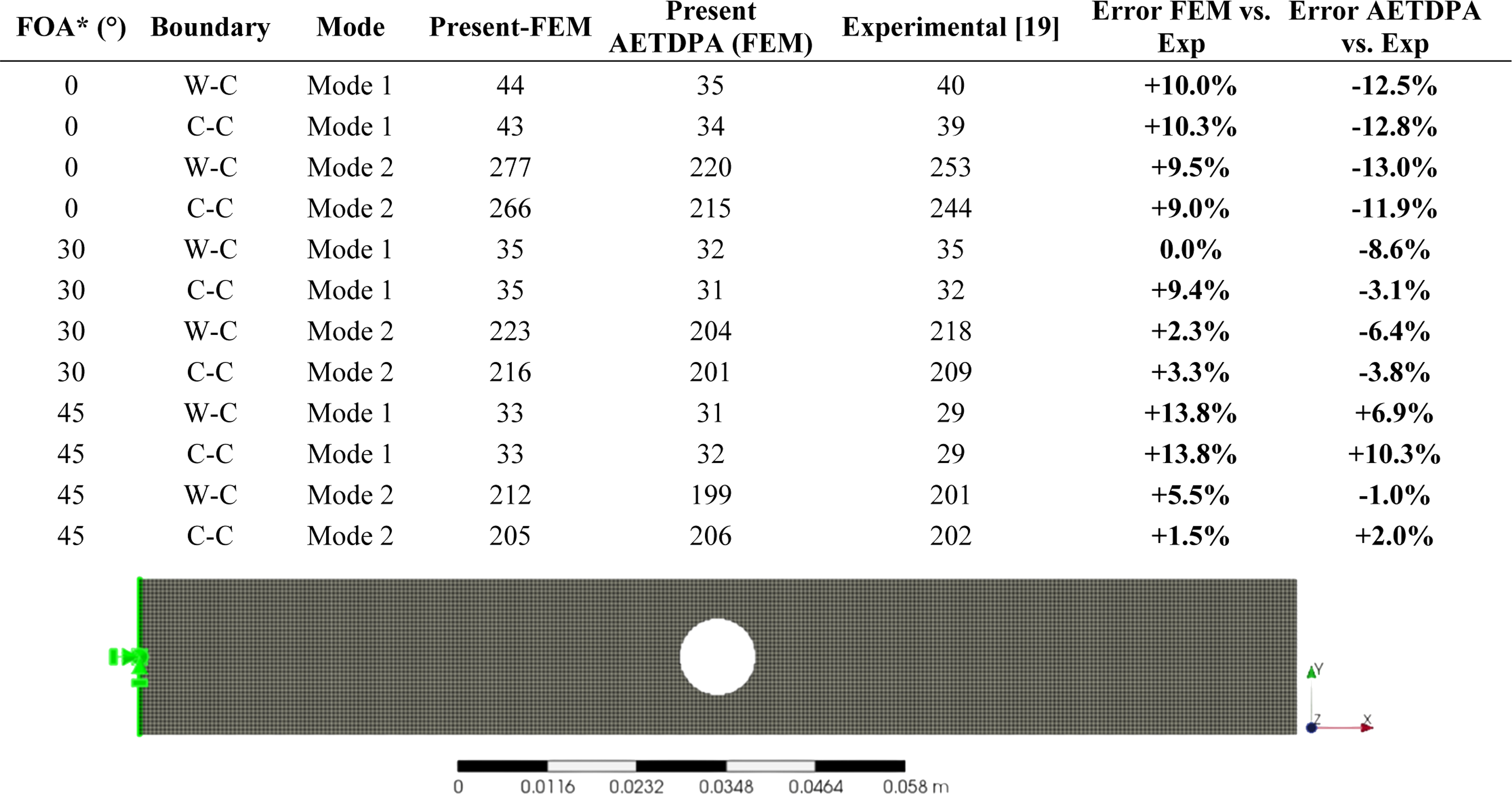
*Fiber Orientation Angle
2.9.3.1. Analysis of results
Elastic FEM results show a consistent tendency to overpredict experimental frequencies, with errors ranging from 0% to +13.8%. The mean absolute error across all 12 cases is
AETDPA results (with calibrated prestress) show a different error distribution: underprediction for 0° cases (-11.9% to -13.0%), mixed results for 30° (-3.1% to -8.6%), and overprediction for 45° (-1.0% to +10.3%). The mean absolute error for AETDPA is
2.9.3.2. Discussion
The experimental validation confirms that both modeling approaches capture the fundamental frequency trends with acceptable engineering accuracy (mean errors < 8%). The AETDPA method, despite its simplified prestress generation, performs comparably to the full elastic analysis while providing additional insight into prestress effects. The calibrated temperature parameters (derived from the 0° W-C case) produce the best agreement for that specific configuration but show systematic biases for other orientations—suggesting that orientation-dependent calibration could further improve accuracy, though this is left for future work.
2.10. Relevance to the present study
Particle-Swarm Optimisation (PSO) is used to explore the high-dimensional design space that contains the four laminate ply angles
In summary, PSO supplies the global-search capability needed to identify the optimal combination of laminate stacking and cut-out geometry, while the AETDP pre-processor furnishes a rapid, independent finite-element analysis that validates the elastic PSO results and explores the effect of temperature-induced prestress without influencing the optimisation itself.
3. Results and discussions
The coupled finite-element/optimisation framework was applied to rectangular laminated plates with a single circular cut-out. Three aspect ratios were investigated (a/b = 1/3, 1/2, and 1) and four boundary-condition families were considered (CFFF, CFCF, CCCF, and CCCC). For every case, the Particle Swarm Optimisation (PSO) search produced a set of optimal design variables (laminate stacking sequence, hole centre •
The prestressed eigenvalue problem solved by CalculiX can be written as:
The tables below summarise the optimum designs and the three frequencies obtained from (i) conventional elastic analysis, (ii) AETD-P-based validation, and (iii) AETD-P-based optimisation. All frequencies are expressed in hertz.
3.1. Optimum configurations for aspect ratio a/b = 1/3
Optimum configurations for composite plates with aspect ratio a/b = 1/3.

The optimum designs reveal several clear trends linked to boundary conditions and prestress effects:
3.1.1. Stacking direction trend
For the least-constrained configurations (CFFF and CFCF), optimal ply angles align predominantly with the x-axis (e.g., CFFF: [0°/-2°/2°/0°]; CFCF: [2°/-1°/-1°/0°]). This alignment places the stiffest fibre direction along the only clamped edge(s), maximizing bending stiffness in the primary load direction—a classic design principle for cantilever-type structures. In contrast, the more highly restrained configurations (CCCF and CCCC) exhibit rotation toward the y-axis (CCCF: [83°/86°/90°/-89°]; CCCC: [-90°/-90°/90°/90°]), reflecting heightened shear demand from additional clamped edges.
3.1.2. Hole-size behavior
The maximum admissible radius (0.120 m) occurs for the CFCF case. This configuration benefits from two clamped edges along the x-direction, providing sufficient stiffness to tolerate a large perforation without catastrophic frequency reduction. Physically, the clamped edges create high-strain regions near the boundaries, while the central region (where the hole is placed) contributes less to overall stiffness. Removing material from this low-strain region minimizes the stiffness penalty while still achieving mass reduction.
The remaining three boundary conditions prefer considerably smaller radii (0.07–0.085 m). For CFFF, the cantilever configuration concentrates strain near the clamped edge; a large hole would intersect this high-strain region, severely degrading stiffness. For CCCC, the fully clamped plate has high strain energy distributed across the entire surface; any hole removal significantly impacts stiffness, so a moderate radius represents the optimal trade-off between mass reduction and stiffness preservation.
3.1.3. Prestress effect
Comparing elastic frequencies with AETD-P-based validation reveals a consistent ∼5% increase across all boundary conditions. This stiffening occurs because the temperature field generates compressive stresses that increase the geometric stiffness matrix contribution KT. When prestress is incorporated directly into the optimisation loop, frequencies rise an additional ∼2%, demonstrating that PSO successfully steers designs toward regions where thermal stiffening is most advantageous—typically where the hole is positioned to align with the compressive stress trajectories.
3.1.4. Modal spacing
The gap between first and second modes contracts markedly as constraint severity increases: from ∼75 Hz for CFFF to ∼2 Hz for CCCC. This dramatic reduction is a direct consequence of modal coupling under high constraint levels. In CFFF, the first mode is a pure bending mode, well-separated from higher modes. In CCCC, the symmetric boundary conditions force the first several modes to cluster, as multiple deformation patterns become energetically similar.
3.2. Optimum configurations for aspect ratio a/b = 1/2
Optimum configurations for aspect ratio a/b = 1/2.

Aspect ratio effects:
As the plate widens from a/b= 1/3 to 1/2, optimal ply angles for partially clamped families (CFFF, CFCF, CCCF) rotate further toward the x-axis. This trend reflects the increasing importance of longitudinal bending stiffness as the plate becomes longer in the x-direction relative to its width. Only the fully clamped CCCC case retains a balanced 90°/90°/90°/90° stacking, which provides equal stiffness in both directions—appropriate for a square-ish plate with symmetric constraints.
3.2.1. Hole centre migration
In the CFFF configuration, the optimal hole centre migrates steadily toward the free edge, reaching Xc 0.96 m. This location coincides with a nodal line of the first bending mode. Positioning the cutout on a nodal line minimizes its detrimental effect on frequency because the modal strain energy is minimal there—material removal causes less stiffness loss than if the hole intersected high-strain regions. This design principle holds across all aspect ratios, demonstrating the importance of modal analysis in guiding cutout placement.
3.2.2. Radius upper bound attainment
For the fully clamped CCCC case, the optimizer pushes the hole radius to the upper bound (0.120 m). Four clamped edges provide such high baseline stiffness that even a large cutout yields a net benefit from mass reduction. This counterintuitive result—that more constraint enables larger holes—arises because the frequency depends on the sqrt(K/M) ratio; when K is very large, modest reductions in K from material removal are outweighed by proportional reductions in M.
3.3. Optimum configurations for aspect ratio a/b = 1
Optimum configurations for aspect ratio a/b= 1.

3.3.1. Square plate behavior
For square plates, the CFFF configuration permits the largest admissible cutout (r = 0.12 m), positioned near the free edge. The mode shape shows a distinct nodal line running approximately diagonally, with the optimal hole placed at the intersection of this nodal line and the free edge—maximizing mass reduction while minimizing stiffness loss. The CCCC case selects a balanced stacking sequence ([−87°/90°/9°/3°]) that distributes stiffness equally along x- and y-directions—natural for a square plate restrained on all edges. The optimal hole (r = 0.103 m) is slightly smaller than the upper bound, indicating that for square plates, the stiffness-mass trade-off peaks before reaching the geometric limit.
3.3.2. Modal separation reversal
Unlike narrower plates, the square plate shows the largest mode spacing for CCCC (≈167 Hz) and the smallest for CFFF (≈4 Hz). This reversal occurs because the square geometry fundamentally alters the mode sequence: for CFFF, the first two modes are closely spaced bending and torsion modes; for CCCC, the symmetric boundary conditions push the first mode to a high frequency while the second mode is significantly higher due to the increased curvature demands.
Mesh convergency is depicted on Figure 2 for CFFF, a/b=1 optimized geometry. And for all the cases 0.012 m mesh size is enough to get correct results as it converges. Convergence history plot for CFFF with reduction of element size.
3.4. Optimal topologies
Optimal topologies achieved by PSO and AETDPA.


Across all aspect ratios, the results demonstrate that optimal hole size, location, fiber orientation, and modal characteristics are strongly dependent on boundary conditions. These interdependencies are highly nonlinear and cannot be predicted reliably using intuitive or parametric approaches alone. Consequently, the application of systematic optimization techniques such as PSO is essential for the reliable dynamic design of laminated composite plates containing cutouts.
Across all aspect ratios and boundary conditions, several robust design principles emerge.
These principles are highly nonlinear and interdependent, confirming that systematic optimization—rather than intuitive rules—is essential for achieving optimal dynamic performance in perforated composite plates.
3.5. Extending cutout applications: Square cutout
To verify the accuracy of the proposed numerical formulation, the predicted natural frequencies obtained from the present AETDPA-based finite element model are compared with experimental results reported in Erkliğ et al.’s studies. 19 The comparison is carried out for laminated composite plates with different fibre orientation angles (FOA) under S–C boundary conditions.

Square cutout with CFFF boundary conditions.

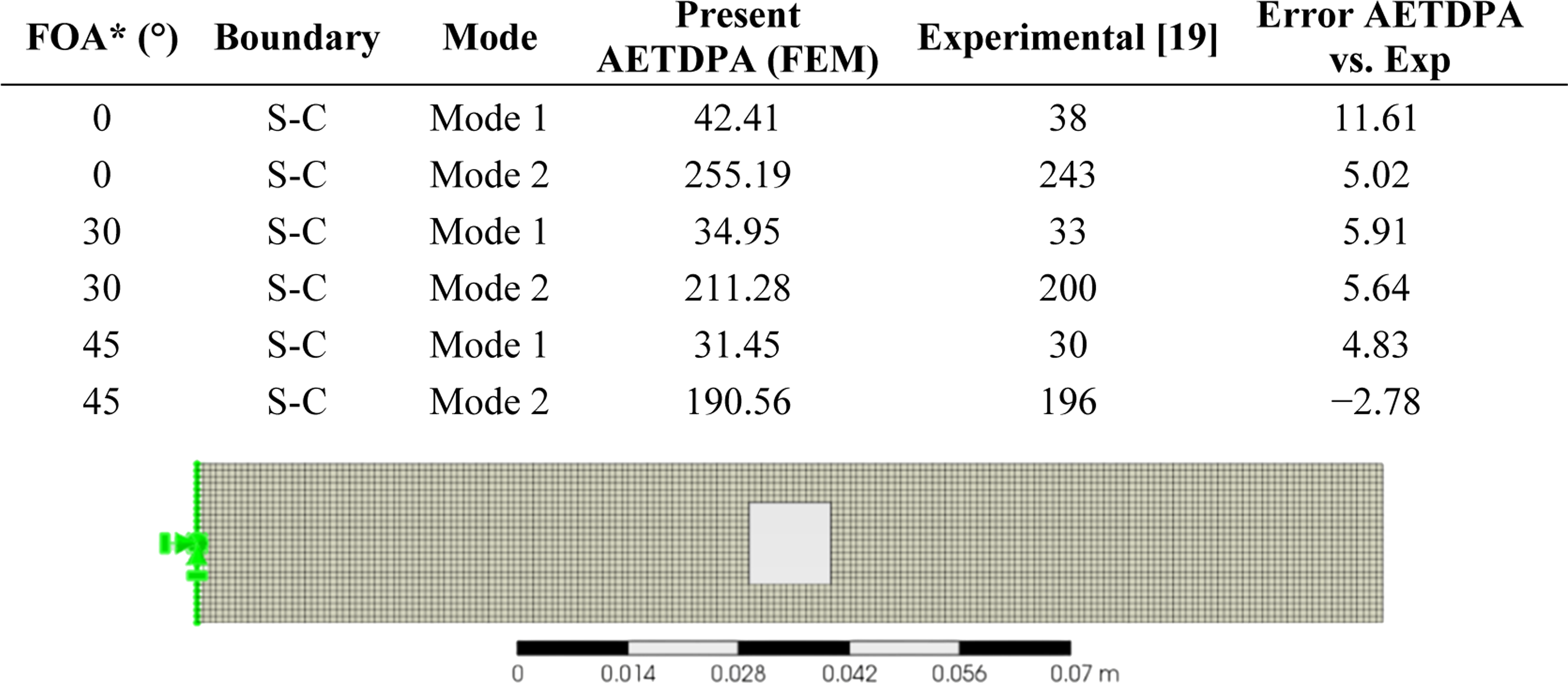
*Fiber Orientation Angle
The results presented in Table 10 demonstrate good agreement between the numerical predictions and the experimental data. The majority of the deviations remain within approximately 6%, while the maximum error is about 11.6% for the first vibration mode at
Overall, the close correlation between the present results and the experimental data reported in Table 10 confirms the reliability and accuracy of the proposed modelling approach for predicting the vibration characteristics of laminated composite plates.
3.6. Sensitivity analysis
The influence of the aspect ratio on the first three natural frequencies under different boundary conditions is illustrated in Figure 3. As the aspect ratio increases from 
As shown in Tables 6–8, the boundary condition has a dominant effect on the vibration characteristics. Plates with fully clamped edges (CCCC) consistently exhibit the highest natural frequencies due to increased structural stiffness, whereas the CFFF configuration produces the lowest frequencies. Increasing the aspect ratio from
The optimal cutout parameters
The AETDPA-based validation results show good agreement with the reference optimum solutions, confirming the reliability and robustness of the proposed optimization approach.
4. Conclusions
This study presented two complementary computational approaches for optimizing the natural frequencies of laminated composite plates containing circular cutouts. The Particle Swarm Optimisation (PSO) algorithm was employed as a classical metaheuristic to explore the combined design space of ply angles (treated as continuous variables in [-90°,90°], rounded to integer degrees), cutout centre coordinates (xc, yc), and cutout radius r. The Adjacent Element Temperature Driven Prestress (AETD-P) method was introduced as a novel pure-finite-element pre-processor that generates temperature-induced prestress fields directly from mesh topology using a breadth-first search algorithm, enabling rapid prestressed modal analysis without coupled heat-transfer simulations.
The following conclusions can be drawn from this investigation.
4.1. Optimal design principles for perforated composite plates
The optimization results reveal several robust design principles that govern the dynamic behavior of perforated composite plates. • • • •
4.2. Performance of the AETDP method
The AETDP method successfully generates physically plausible prestress fields with minimal computational cost (2–3 seconds for temperature field generation; 30–60 seconds for complete prestressed modal analysis). Key findings include. • Prestress consistently increases fundamental frequencies by approximately 5% compared to elastic analysis across all tested configurations. • When prestress is incorporated directly into optimization, an additional ∼2% frequency improvement is achieved, demonstrating that optimizers can exploit thermal stiffening effects. • Validation against experimental data
19
shows that AETDP (with parameters calibrated from a single reference case) achieves mean absolute errors of 7.2%, comparable to the 7.4% error of the elastic FEM model. This confirms that the simplified prestress generation approach does not compromise engineering accuracy.
4.3. Computational considerations
The PSO-based full-space optimization (simultaneous optimization of angles, hole location, and radius) requires approximately 50,000 FE evaluations per run (100 particles × 500 iterations), corresponding to ∼8 days of CPU time on a standard workstation. The AETDP-based angle-only optimization (optimizing four ply angles while keeping cutout geometry fixed) completes in ∼8 hours—a speed-up of more than an order of magnitude. This efficiency makes AETDP attractive for parametric studies and preliminary design exploration, while full PSO remains viable for final design refinement.
4.4. Study limitations and future work
The present study has several limitations that should be acknowledged: • • • • • It is important to acknowledge a limitation of the present study: it does not include a direct benchmarking of PSO against other metaheuristic algorithms, such as Genetic Algorithms (GA) or Simulated Annealing (SA), for the specific multi-objective function considered. While our selection of PSO is informed by prior comparative studies,
29
a dedicated benchmarking campaign would further strengthen the claims regarding its optimality for this class of problem. Such a comparative analysis, which would provide quantitative performance metrics for each algorithm, is a clear direction for future research.
4.5. Summary
This work demonstrates that systematic optimization—rather than intuitive design rules—is essential for maximizing the dynamic performance of perforated composite plates. The proposed PSO-AETDP framework provides a computationally efficient workflow that simultaneously considers laminate configuration, cutout geometry, and prestress effects. The AETDP method offers a novel approach to incorporating prestress into modal analysis without the computational burden of coupled thermal-structural simulations. By releasing the complete source code as open-source material, the authors hope to enable other researchers to reproduce, validate, and extend this work to broader classes of composite structures.
Supplemental Material
Supplemental Material - Natural frequency optimization of composite plates with cutouts
Supplemental Material for Natural frequency optimization of composite plates with cutouts by Mustafa Akbulut, Ibrahim T. Teke, and Ahmet H. Ertas in Journal of Low Frequency Noise, Vibration and Active Control.
Footnotes
Funding
The authors certify that they have NO affiliations with or involvement in any organization or entity with any financial interest (such as honoraria; educational grants; participation in speakers’ bureaus; membership, employment, consultancies, stock ownership, or other equity interest; and expert testimony or patent licensing arrangements), or non-financial interest (such as personal or professional relationships, affiliations, knowledge or beliefs) in the subject matter or materials discussed in this manuscript. Additionally, this research did not receive any specific grant from funding agencies in the public, commercial, or not-for-profit sectors.
Declaration of conflicting interests
The authors declared no potential conflicts of interest with respect to the research, authorship, and/or publication of this article.
Supplemental Material
Supplemental material for this article is available online.
References
Supplementary Material
Please find the following supplemental material available below.
For Open Access articles published under a Creative Commons License, all supplemental material carries the same license as the article it is associated with.
For non-Open Access articles published, all supplemental material carries a non-exclusive license, and permission requests for re-use of supplemental material or any part of supplemental material shall be sent directly to the copyright owner as specified in the copyright notice associated with the article.