
Abstract
Reducers used in robotic joints often provide only a limited range of transmission ratios, while remaining bulky and imposing relatively high sliding velocities on the meshing tooth pairs. This work presents the mechanism design and dynamic analysis of a novel Double Differential Reducer intended for compact high-ratio transmission. The reducer employs a special internal planetary arrangement that substantially reduces the input speed, and the desired transmission ratio can be obtained by finely adjusting the tooth numbers. A symmetric transmission layout further enhances power density while preserving a compact overall envelope. To investigate the dynamic behaviour of the transmission system, a nonlinear dynamic model is developed that incorporates backlash, time-varying mesh stiffness, meshing damping and static transmission error. The resulting equations of motion are numerically integrated using a classical fourth-order Runge–Kutta scheme, and the dynamic response under different rotational speed excitations is examined to clarify the global vibration characteristics of the reducer. A dedicated test bench is constructed and prototype tests are carried out to validate the model. The comparison between numerical and experimental results shows that the proposed dynamic model predicts the vibration characteristics of the Double Differential Reducer with good accuracy and provides a useful basis for the design of stable and reliable operation. The results also indicate that the transmission system exhibits stable periodic vibration under high-speed excitation, which supports the use of the proposed reducer in high-speed transmission applications.
Keywords
1. Introduction
Driven by converging market demand, technological progress and policy incentives, the robotics industry has developed rapidly in recent years. In robotic joints, the reducer is the key actuator for motion and attitude control, and its performance has a direct influence on the overall system. With the expansion of robotic application scenarios and the continuous emergence of new technologies, particularly the rapid growth of humanoid robots, the operating conditions encountered by robots are becoming increasingly demanding. 1 Consequently, the development of efficient and compact reducer architectures for robots, together with the investigation of their dynamic behaviour under varying operating conditions, has become an important research topic. 2 To increase joint power density under miniaturization and lightweight requirements, designers commonly seek to raise the transmission ratio of the joint reducer. 3 However, achieving a high transmission ratio while preserving a compact structure and sufficient load-carrying capacity remains a challenging technical problem. 4
Currently, reducers for robot joints are mainly of three types: cycloidal pinwheel reducers, harmonic reducers and planetary reducers. Cycloidal pinwheel reducers provide high-torque transmission, but their limited meshing area makes them susceptible to overheating and wear, which restricts their use at high speeds. They also impose stringent requirements on manufacturing and assembly accuracy.5–9 Harmonic reducers offer high positioning accuracy, yet their relatively low structural stiffness limits their ability to carry large torques and withstand impact loads.10–12 In recent years, planetary reducers have been increasingly adopted in robots operating in highly dynamic scenarios, especially humanoid robots, owing to their balanced overall performance. Nevertheless, for planetary reducers there remains an inherent trade-off between increasing the transmission ratio and maintaining a compact structure and sufficient load-carrying capacity.13–16
Different types of reducers exhibit distinct reduction-ratio characteristics, since the attainable ratio and overall dimensions are strongly constrained by the transmission principle and structural layout. For cycloidal pinwheel, harmonic and planetary reducers, the main engineering strategies used to realise a wide reduction-ratio range can be summarised as follows: (1) Cycloidal pinwheel reducers generally require auxiliary mechanisms such as transmission pins for power output, which reduces the compactness of the overall structure. In addition, the transmission ratio is usually adjusted by changing the number of pinwheels, a strategy that readily increases the overall diameter of the reducer. Increasing the number of pinwheels to obtain a higher transmission ratio also deteriorates backdrivability, that is, the ability of the output to drive the input, making this type of reducer unsuitable for applications that demand precise force control.17,18 (2) For harmonic reducers, the available ratio range is typically adjusted by modifying either the tooth number of the flexspline or the tooth-number difference between the flexspline and the circular spline. However, the tooth number of the flexspline is approximately proportional to the transmission ratio of the reducer, which is unfavourable for achieving a compact structure.
19
Adjusting the tooth-number difference increases the difficulty of tooth profile design, tightens the allowance for profile modification and amplifies the fluctuation of the transmission error.
20
Industrial practice indicates that, in order to maintain transmission accuracy, efficiency and manufacturability, the tooth-number difference in harmonic reducers is most commonly set to two, which inherently limits the achievable reduction-ratio range.
21
(3) For planetary reducers, a common approach to adjust the reduction-ratio range at the product level is to vary the number of series planetary stages. However, as the number of stages increases, the overall dimensions of the reducer grow significantly and the transmission efficiency decreases multiplicatively. This approach is therefore poorly suited to current embodied intelligent robots, which impose particularly stringent requirements on energy efficiency.22–24
Building on the transmission principle of the Double Differential Reducer originally proposed by Hermann J. Stadtfeld for new energy vehicle applications, 25 this study develops a new Double Differential Reducer configuration featuring a double-layer arrangement with a small tooth-number difference. With essentially no change in the mass and inertia of the internal gears, a wide range of transmission ratios can be obtained simply by finely adjusting the tooth numbers, while a symmetric structural layout is adopted to further increase power density. Although the transmission principle of the Double Differential Reducer was introduced in 2020, its prototype realisation and dynamic characteristics have not yet been systematically investigated. To address this gap, and drawing on established dynamic models of spiral bevel gears,26–32 eight spiral bevel gears are coupled to construct a full-system dynamic model of the reducer, and the resulting dynamic response characteristics are analysed in detail.
This study proposes the structural design and dynamic modelling of a new Double Differential Reducer. The reducer adopts a double layer less tooth differential transmission principle to realise differential power distribution, enabling a wide range of transmission ratios without increasing the overall dimensions of the reducer. To reduce the sensitivity of the spiral bevel gear pairs to assembly errors, the configuration of the planetary gear train is improved, which lowers manufacturing difficulty and enhances overall transmission accuracy. The double layer less tooth differential transmission principle is analysed and a mathematical description of the double layer tooth difference is derived to support transmission ratio calculation and subsequent structural optimisation. A nonlinear dynamic model with 21 degrees of freedom is then formulated for the new transmission configuration and solved by a fourth order Runge–Kutta numerical integration scheme.33–35 Additionally, the He’s frequency formulation method36,37 was employed to describe the solution results. The influence of rotational speed excitation on the dynamic characteristics of the Double Differential Reducer is investigated in detail. A dedicated prototype and test bench are developed to validate the model and to characterise the dynamic response experimentally. The main contributions of this work are summarised as follows: (1) The structural design of the reducer is developed on the basis of the double layer less tooth differential transmission principle. Two rigidly connected planet gears are integrated into a single component, and a 21-degree-of-freedom nonlinear dynamic model for the new Double Differential Reducer is established. (2) The dynamic model of the Double Differential Reducer is formulated and solved in detail. The dynamic characteristics of the reducer under different rotational speed excitations are analysed, which provides guidance for achieving stable and reliable operation. (3) A prototype Double Differential Reducer is developed, and its dynamic characteristics are verified experimentally using the dedicated test bench.
The remainder of this paper is organised as follows. Section 2 presents the structural design, transmission principle and dynamic model of the Double Differential Reducer transmission system. In Section 3, the governing vibration equations are derived, including the normal relative displacements and meshing forces of the gear pairs, and are then written in non-dimensional form to facilitate numerical solution. Section 4 analyses the dynamic response of the system, with emphasis on the time- and frequency-domain characteristics under different rotational speeds. Section 5 describes the development of a Double Differential Reducer prototype and the corresponding experimental tests used to validate the dynamic model. Finally, Section 6 summarises the main conclusions of the study.
2. Transmission system of the double differential reducer
2.1. Structural design of the double differential reducer transmission system
The simplified schematic of the Double Differential Reducer transmission system is shown in Figure 1(a). The system comprises eight symmetrically arranged bevel gears, which increase the power density of the reducer. A double layer less tooth differential structure is adopted, with the outer bevel gears nested around the inner bevel gears. The power flow is as follows. The input gear Z1 transmits power to gears Z2 and Z3, and both gears Z2 and Z3 mesh with gear Z4. Because gear Z4 is rigidly connected to the reducer housing, the revolution Double differential reducer transmission system.
The structural design of the Double Differential Reducer is illustrated by the three dimensional model of the transmission system in Figure 1(b). All eight bevel gears are spiral bevel gears. The outer gear set provides differential splitting of the power, whereas the inner gear set combines the power for output. Two power paths are formed, which are strictly symmetric with respect to the input and output axes, resulting in a relatively high power density. The planet shaft is designed with adjustable mounting features for the planet gears, which reduces manufacturing and assembly difficulty, lowers the sensitivity of the spiral bevel gears to installation errors and helps to ensure the overall transmission accuracy and performance of the reducer.
2.2. Transmission principle of the double differential reducer
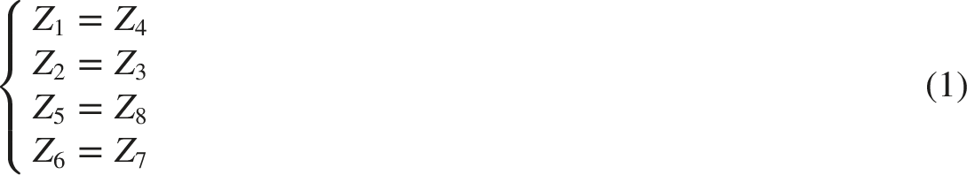
To ensure coaxial input and output and symmetric power distribution, the tooth numbers of the gears in the Double Differential Reducer are constrained by the following relationship.
Assuming rigid transmission between each gear pair, the speed relationships of the outer bevel gears are given by Eq. (2) and Eq. (3).


The rotational speed relationship of the inner bevel gears is expressed in Eq. (4).

From Eq. (2) and Eq. (3)., the angular velocity of the revolution of the planet carrier is obtained, and the rotational angular velocities of the planet gears at both ends of the planet shaft then follow.


Substituting these relationships into Eq. (5) yields a general expression for the angular velocity of the output gear Z8.

Since gear Z4 is rigidly connected to the housing,
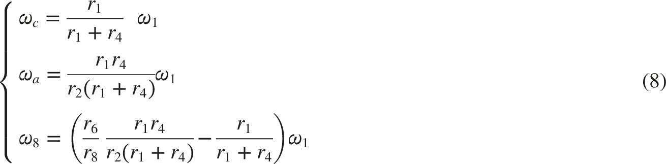
Using the equivalent radius at the pitch circle of the gears

2.3. Dynamic model of the double differential reducer transmission system
The dynamic model of the Double Differential Reducer transmission system is shown in Figure 2 and comprises a total of 21 degrees of freedom. Dynamic model of the double differential reducer transmission system.
A Cartesian coordinate system

3. System equation of motion formulation
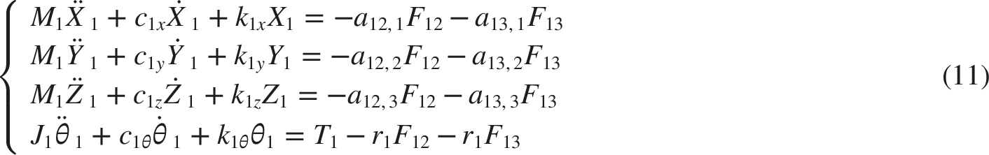
Based on the dynamic model of the Double Differential Reducer transmission system shown in Figure 3 and the analysis in the previous two subsections, the overall dynamic model of the reducer is established using the lumped-mass method. The vibration differential equations of the system can be divided into five parts. Bifurcation diagram of the gear pair at meshing point 12.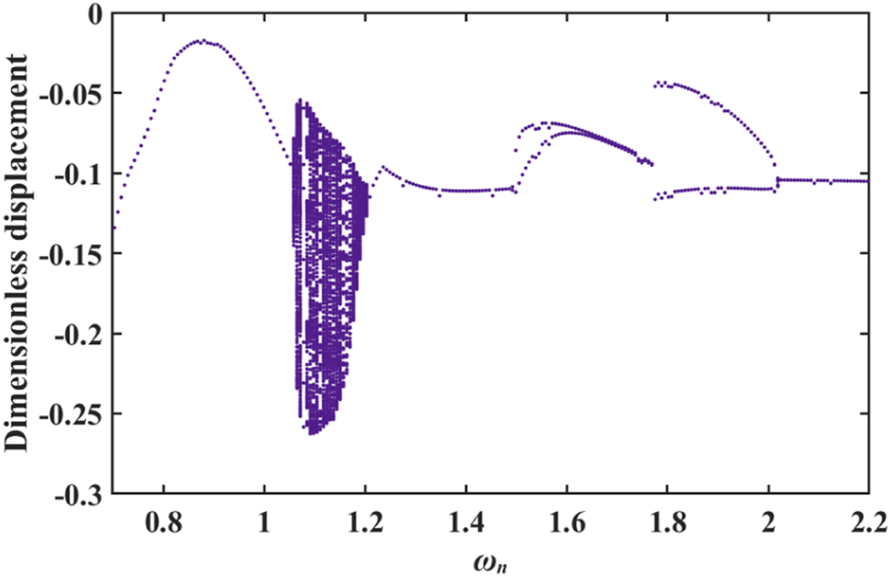
The vibration differential equation for gear 1 is:
The vibration differential equation for planetary gear body 26 is:
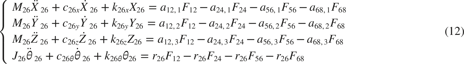
The vibration differential equation for planetary gear body 37 is:
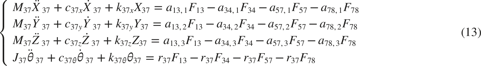
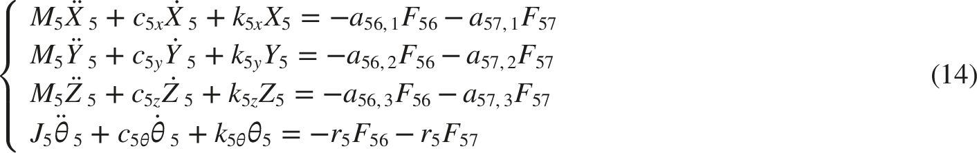
The vibration differential equation for gear 5 is:
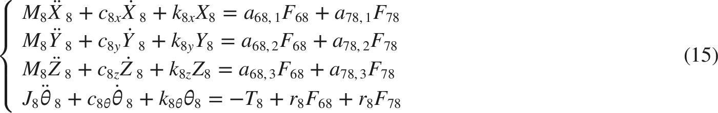
The vibration differential equation for gear 8 is:
The vibration differential equation for the planet carrier is:

3.1. Relative displacement
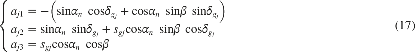
The direction cosines of the unit vector along the normal direction of the meshing point in the Cartesian coordinate system are given by
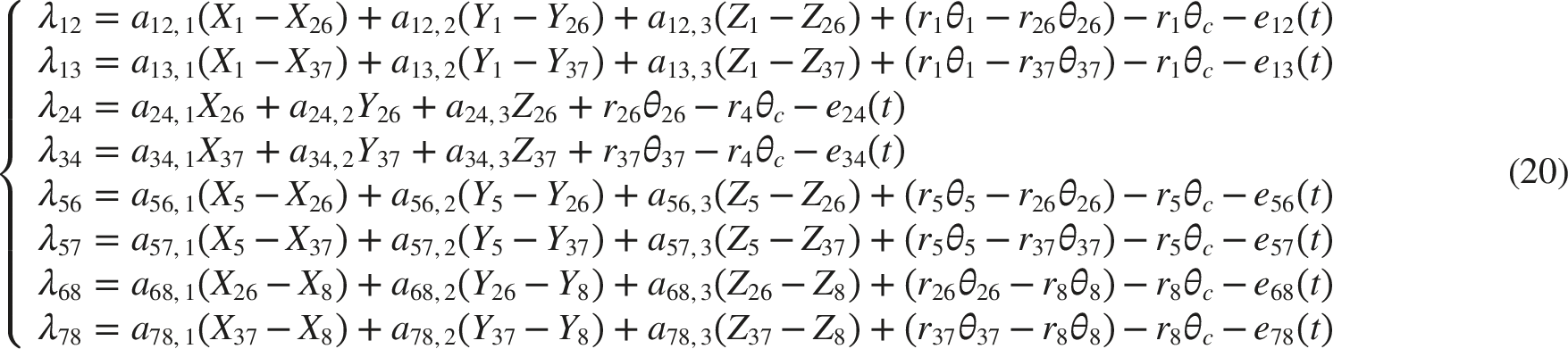
By projecting the relative displacements of the two gears in each meshing pair along the X, Y and Z directions onto the normal direction of the meshing point,38–41 the normal relative displacement at each meshing point of the gear pairs in the transmission system due to vibration and error is obtained as

In this expression,
e
j
(t) denotes the normal composite error of the gear pair, which is decomposed into a mean component and a harmonic component:

The normal relative displacements at the eight meshing points are expressed as:
3.2. Meshing force
Gears exhibit pronounced nonlinear behaviour during meshing, mainly due to internal nonlinear dynamic excitations such as time-varying mesh stiffness, meshing damping and backlash clearance.32–47
The normal time-varying mesh stiffness at the meshing point of a gear pair is given by:

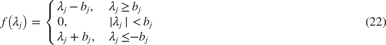
The nonlinear tooth flank clearance function is written as:
The normal meshing force of the

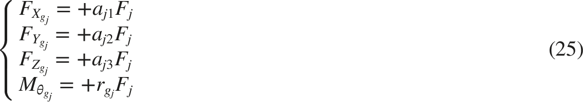
The force and torque acting on the driving gear P in the

The force and torque acting on the driven gear G in the
The equivalent torque of the

Therefore, the total equivalent torque acting on the planet carrier is:

3.3. Final dimensionless equations
By transforming vibration Eqs. (11)–(16) into dimensionless form, the original physical quantities are converted into dimensionless variables. This treatment reduces numerical interference associated with units in the solution process, improves the efficiency of the numerical integration and facilitates comparison of the obtained results.
The dimensionless normal relative displacements at the eight meshing points are given by:
The dimensionless differential equation for each degree of freedom is:
Structural parameters of the double differential reducer transmission system.
Dynamic parameters of the double differential reducer transmission system.
4. Dynamic response of the transmission system
Due to the continuous variation of backlash and mesh stiffness during gear meshing, the system exhibits complex nonlinear dynamic behaviour under the combined action of internal and external excitations. Based on the 21-degree-of-freedom dynamic model of the Double Differential Reducer transmission system, the equations of motion are solved using a variable-step fourth-order Runge–Kutta method. To eliminate the influence of initial transients, the non-steady response is discarded and only the steady-state response is used for analysis. A load torque of 200 N·m is applied, and the nonlinear dynamic response of the system at different meshing positions is investigated by examining the normal relative displacement, velocity, acceleration, frequency spectrum, phase portrait, Poincaré map and bifurcation diagram, in order to clarify the vibration characteristics of the system.
4.1. Gear pair Z1–Z2
The initial meshing position of gear pair Z1–Z2 after power input is shown in Figure 3, which presents the bifurcation diagram of this gear pair at meshing point 12. The bifurcation parameters are the dimensionless speed excitation and the normal relative displacement at the dimensionless meshing point. As the excitation varies, the motion state of the gear pair at this meshing point follows a period 1–chaotic–period 1–period 2 sequence.
As shown in Figure 4, the nonlinear response at meshing point 12 under Period-1 response at meshing point 12 under 
When the dimensionless speed excitation increases to 1.151, the motion state changes, as illustrated in Figure 5, and the nonlinear response exhibits a typical chaotic behaviour. The normal relative displacement shows irregular multi-amplitude motion, the phase portrait consists of irregular, interlaced rings, and the Poincaré section contains many non-coincident discrete points. Meanwhile, the corresponding frequency spectrum presents multiple side-frequency components in addition to the dominant peak. These characteristics consistently indicate that the system enters a chaotic regime at this excitation level. Chaotic response at meshing point 12 under 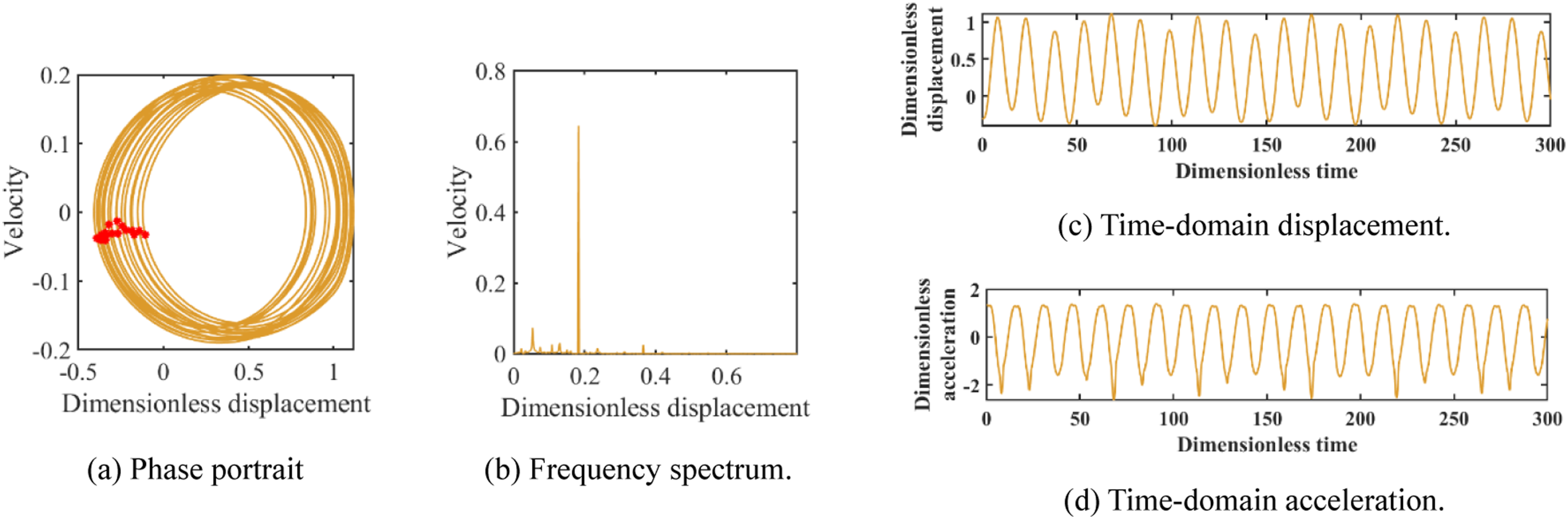
With a further increase of the dimensionless speed excitation to 1.874, the nonlinear response evolves to a typical period-2 motion, as shown in Figure 6. The normal relative displacement alternates between two distinct amplitudes, the phase portrait consists of two closed rings, and the Poincaré section presents two concentrated points. Meanwhile, the corresponding frequency spectrum exhibits two dominant components, indicating the emergence of a subharmonic response. These characteristics consistently confirm that the system operates in a stable period-2 regime at this excitation level. Period-2 response at meshing point 12 under 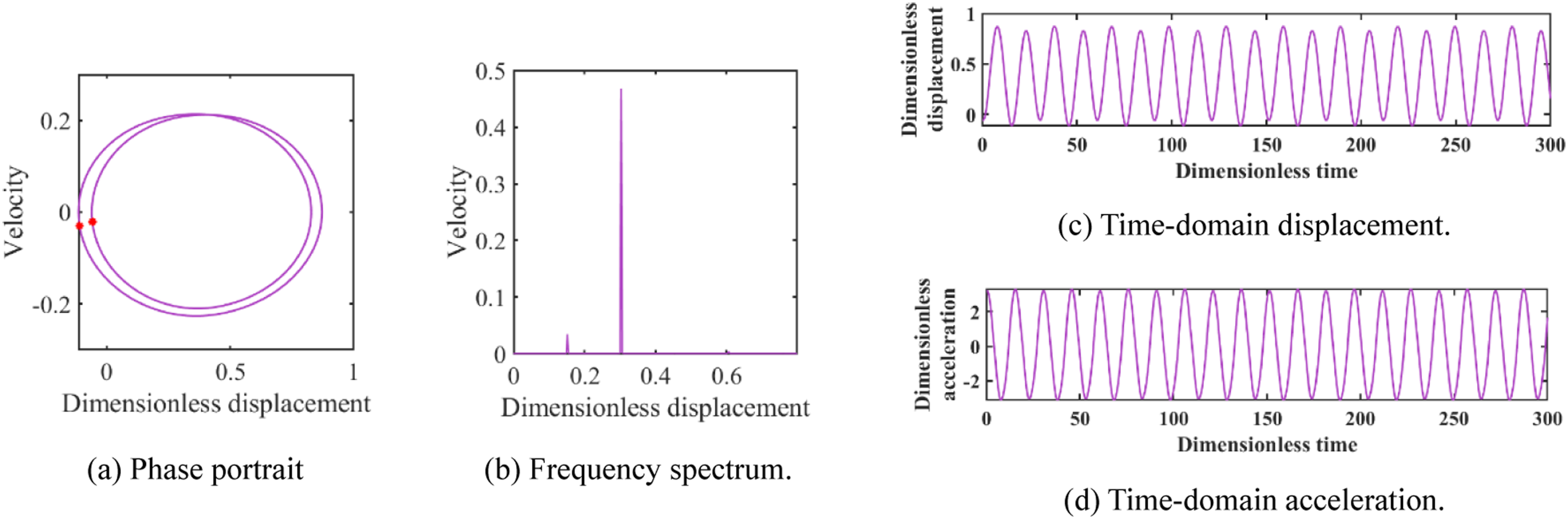
4.2. Dynamic response at meshing pairs 68 and 56
In the transmission system of the Double Differential Reducer, the gears are arranged symmetrically. In this subsection, meshing pair 68 and meshing pair 56 are compared. Gear pair Z6–Z8 corresponds to the meshing position where power is delivered to the output, with Z8 carrying the external load. Figure 7 shows the bifurcation diagrams of the gear pair at meshing points 68 and 56. For both meshing points, the system follows a period 1–chaotic–period 1–period 2 sequence. Gear Z5 provides support and splits the power flow, and the motion at meshing point 56 also follows a period 1–chaotic–period 1–period 2 pattern. However, the bifurcation diagram shows that the motion at meshing point 56 is more strongly chaotic than at meshing point 68, with a wider chaotic region and a larger displacement span in the period 2 regime. Bifurcation diagrams of the gear pairs at meshing points 56 and 68.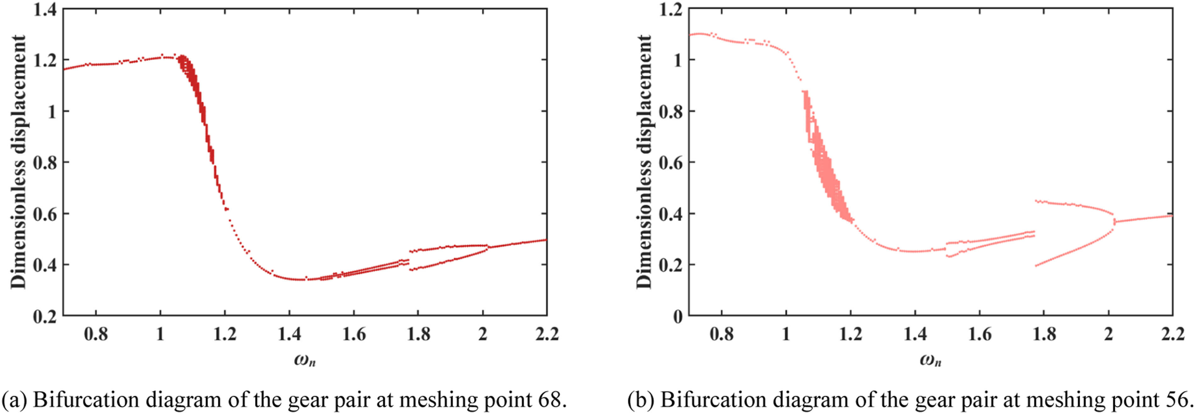
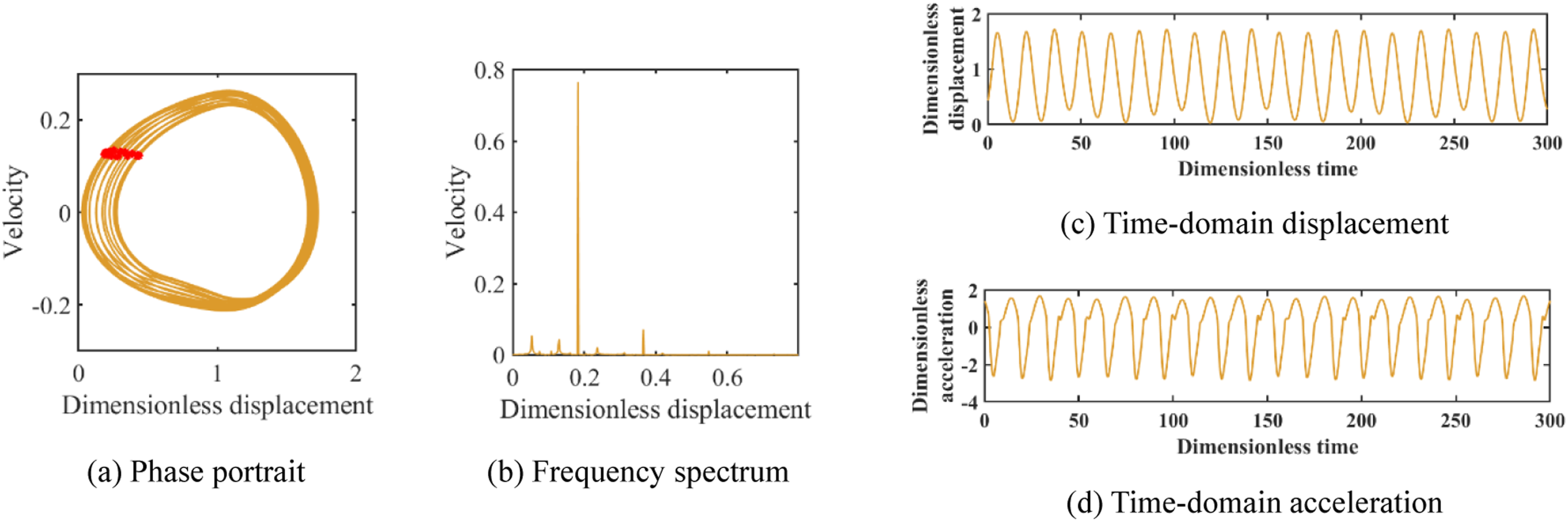
As shown in Figures 8 and 9, the nonlinear responses at meshing points 68 and 56 under a dimensionless speed excitation of 0.789 both exhibit typical period-1 motions. The normal relative displacements show stable, single-amplitude periodic waveforms, and the phase portraits form closed rings with a single concentrated Poincaré point. The corresponding frequency spectra are dominated by one dominant frequency, with only small-amplitude secondary components. Notably, the vibration amplitude at meshing point 68 is smaller than that at meshing point 56, indicating that the gear pair near the output end is dynamically more stable at this excitation level. These characteristics consistently confirm that the system remains in a stable single-periodic regime under Period-1 response at meshing point 68 under Period-1 response at meshing point 56 under 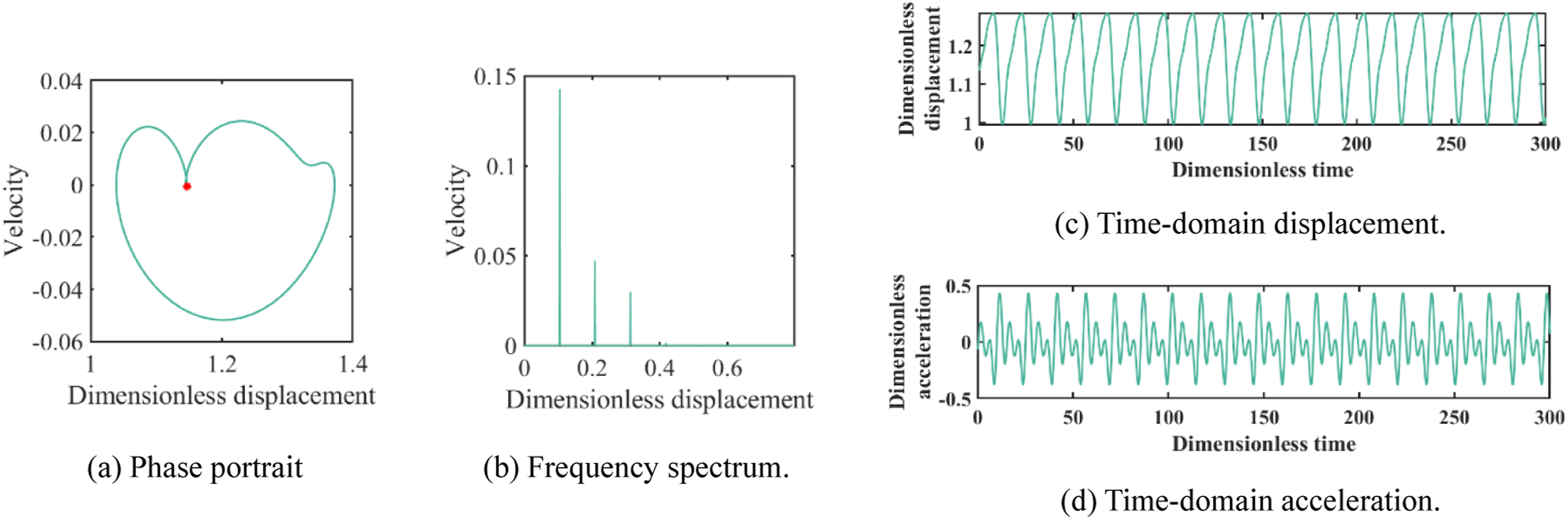

When the dimensionless speed excitation increases to 1.17, the motion state changes, as illustrated by the responses in Figures 10 and 11 for the two meshing points. At this excitation level, the nonlinear responses exhibit typical chaotic behaviour. The normal relative displacements show irregular multi-amplitude motion, the phase portraits display irregular, staggered rings, and the Poincaré sections contain numerous non-coincident points. Meanwhile, the corresponding frequency spectra present multiple prominent secondary components in addition to the dominant peak, and meshing point 56 exhibits richer low- and high-frequency contents. These characteristics consistently indicate that the system enters a chaotic regime at this excitation level. Chaotic response at meshing point 68 under Chaotic response at meshing point 56 under 
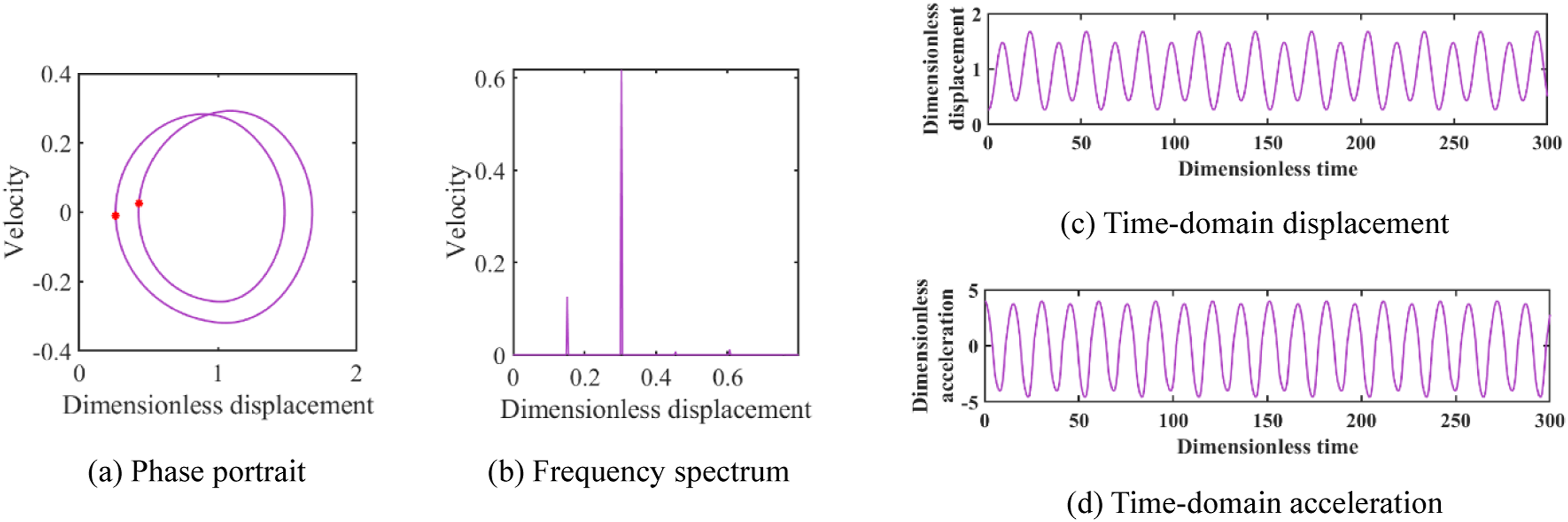
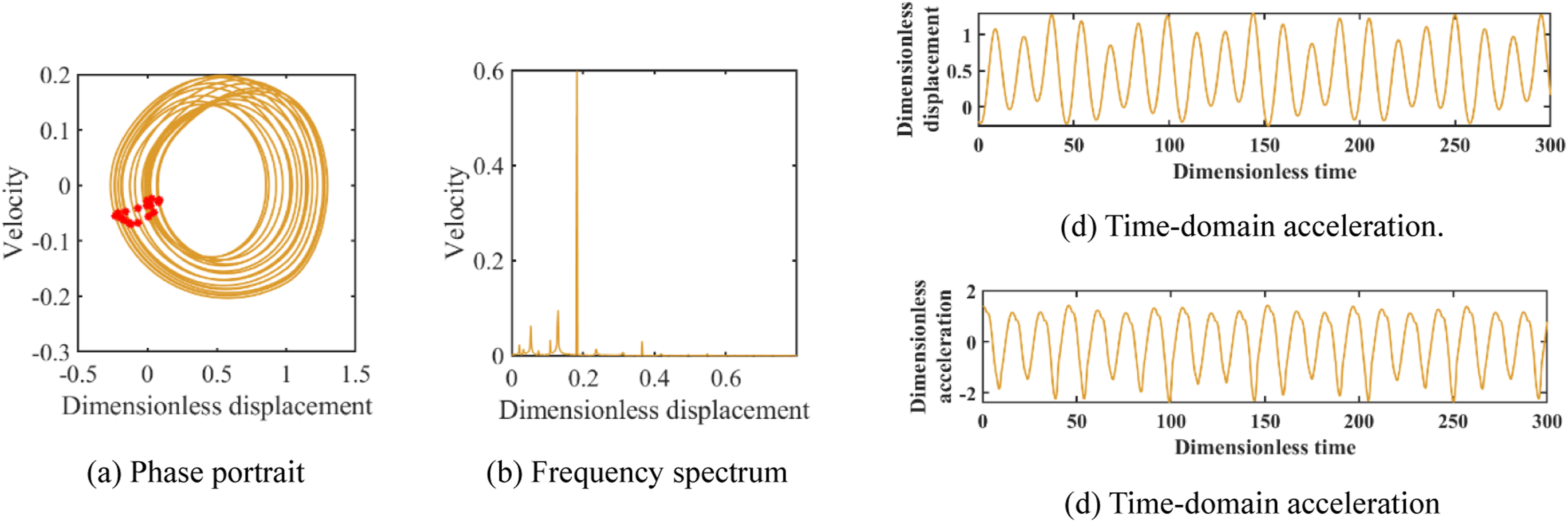
With a further increase of the dimensionless speed excitation to 1.9, the response transitions from chaos, briefly returns to a period-1 regime, and then settles into a period-2 motion, as shown in Figures 12 and 13. The phase portraits form two smooth closed loops, and the Poincaré sections exhibit two concentrated points, which is characteristic of a period-doubling response. In the frequency domain, the spectra show a pronounced 1/2 subharmonic component, confirming the emergence of a stable period-2 state at this excitation level. Period-2 response at meshing point 24 under Period-2 response at meshing point 24 under 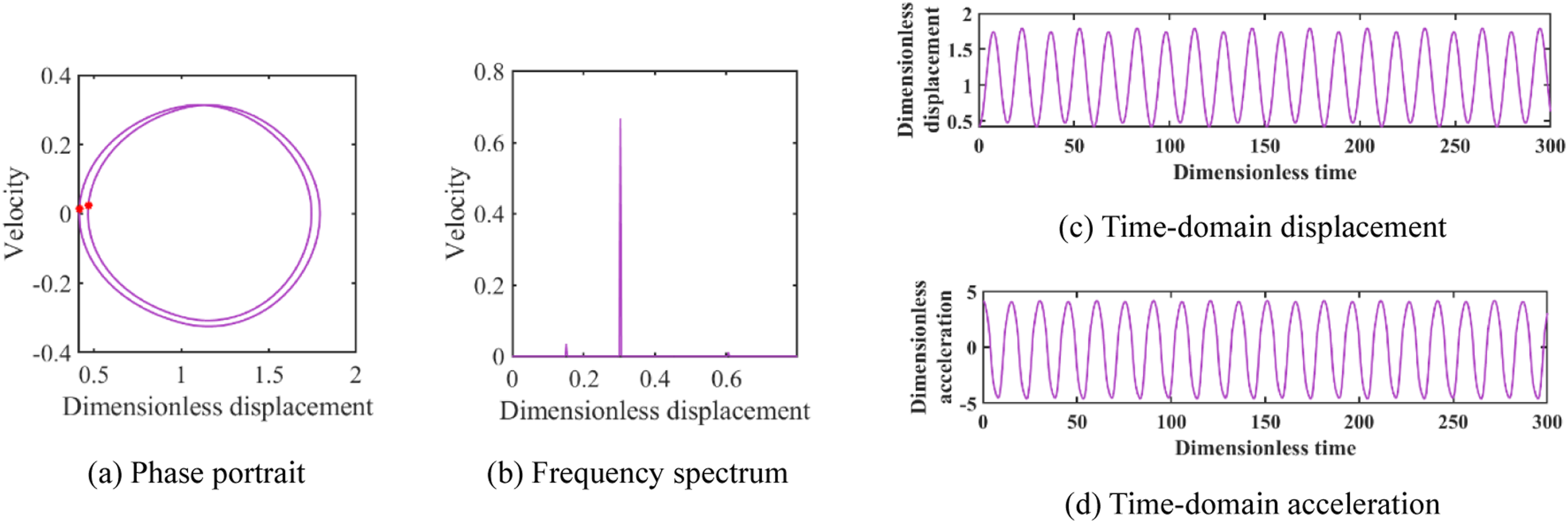
4.3. Gear pair Z2–Z4
Gear Z4 is a fixed gear, and Figure 14 shows the bifurcation diagram of the gear pair at meshing point 24. The motion of the system at this meshing point follows a period 1–chaotic–period 1–period 2 sequence. Bifurcation diagram of the gear pair at meshing point 24.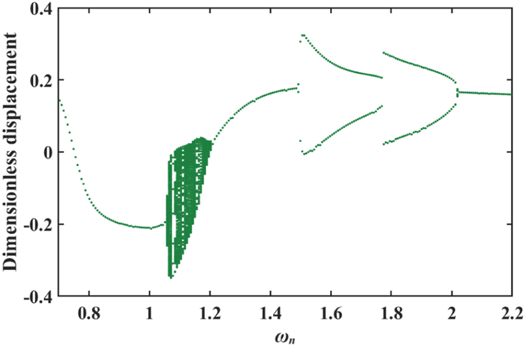
When the dimensionless speed excitation is 0.8, the system remains in a period-1 regime, with a stable single-amplitude waveform, a single closed orbit in the phase portrait, and a spectrum dominated by the dominant frequency. As the excitation increases to 1.15, the response becomes chaotic: the displacement varies irregularly with multiple amplitude levels, the phase trajectory spreads into irregular rings, and the Poincaré points are widely scattered, accompanied by richer secondary frequency components. With a further increase to 1.58, the system first briefly returns to a period-1 motion, and then transitions to a period-2 response, evidenced by the splitting of the orbit into two closed rings and the appearance of a clear 1/2 subharmonic component in the spectrum.
4.4. Bifurcation characteristics of the system considering bearing clearance
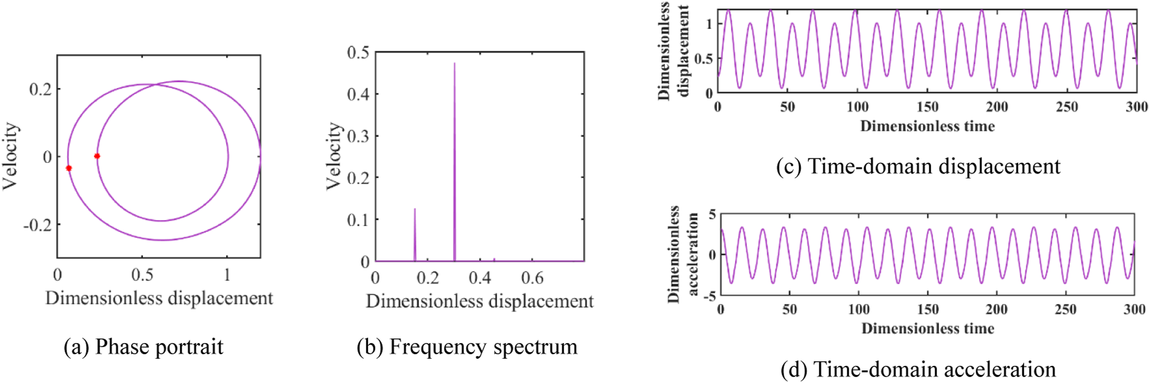
Clearance acts as a strong nonlinear factor and has a significant influence on the vibration response of the system. In the reducer, the installation of bearings introduces radial clearance at the gear supports. Owing to the high sensitivity of bevel gears to mounting errors, incorporating bearing clearance into the model better reflects the actual operating conditions of the reducer. The nonlinear radial bearing clearance is expressed as: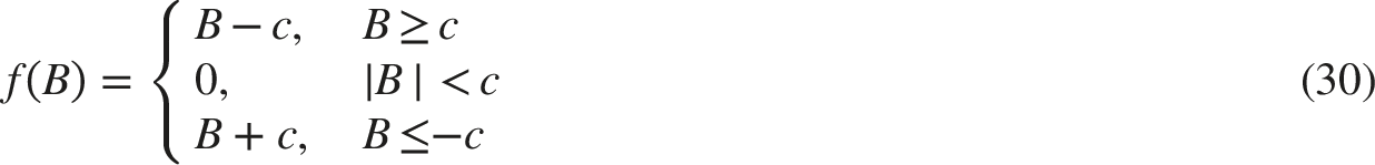
In this expression, c is the bearing clearance. For gear 1, the radial clearance B is represented by
The bifurcation characteristics of the system are analysed by introducing bearing clearances (Figures 15–17). Based on the dynamic characteristics of the transmission system discussed in the previous subsection, the bifurcation trends at the four meshing points are essentially the same. Therefore, only the phase portrait, frequency spectrum and transmission error at meshing point 68 under a dimensionless speed excitation of 0.986 are presented here. The results for a bearing clearance of 1 μm are shown in Figure 18, and those for a bearing clearance of 10 μm are shown in Figure 19. From the analysis results it can be seen that, after the strong nonlinearity associated with bearing clearance is included, the system exhibits more pronounced chaotic vibration, and the onset of chaos occurs at lower excitation levels. However, the overall evolution still follows a period-1–chaotic–period-1–period-2 pattern, indicating that the system response becomes more irregular when bearing clearance is taken into account. As the bearing clearance increases, the system exhibits more pronounced chaotic vibration, the system remains in a chaotic state even at lower speed excitations, the amplitude of the main frequency component increases from 0.233 to 0.456, less sidebands appear, and the peak-to-peak value of the transmission error increases. Therefore, when selecting bearings, both the dynamic performance and cost requirements should be considered in order to adopt sufficiently high precision bearings. Period-1 response at meshing point 24 under Chaotic response at meshing point 24 under Period-2 response at meshing point 24 under Vibration characteristics of the system with a bearing clearance of 1 μm. Vibration characteristics of the system with a bearing clearance of 10 μm.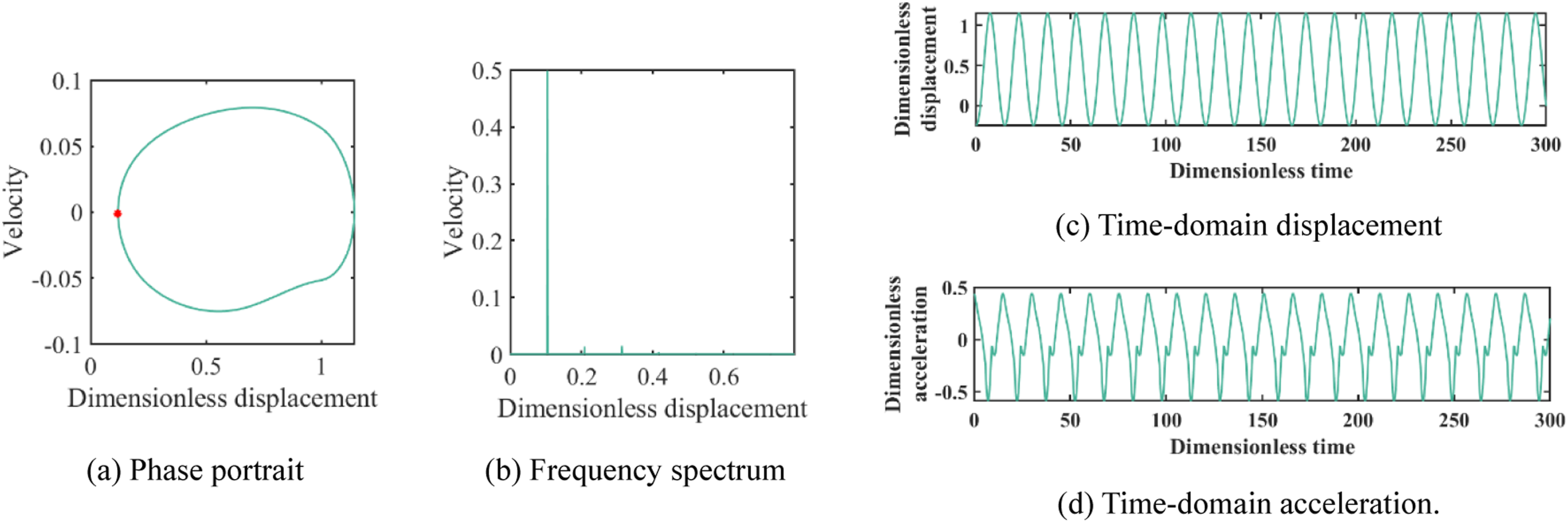


5. Experimental investigation
5.1. Experimental test bench and test procedure
To validate the proposed nonlinear dynamic model of the DDR transmission system, a dedicated experimental test bench was designed and constructed, as shown in Figure 20. The bench comprises three parts: a precision mechanical transmission platform, a hardware acquisition and control system, and test software for synchronised data recording and post-processing. Comprehensive performance test bench for the reducer.
As the dynamic response of precision reducers is highly sensitive to installation errors, the geometric accuracy of the bench was strictly controlled. During the design, machining and assembly stages, the coaxiality of the shaft units at both ends of the tested reducer was maintained within 3 μm, and the radial runout of the connecting shaft at the reducer output end was controlled to within 5 μm during assembly. To further reduce measurement bias due to encoder eccentricity, the selected circular grating angle sensor adopted a dual-readhead configuration, which effectively suppresses the eccentricity error of the grating disk.
Angle sensors and torque sensors were installed at both the input and output ends of the reducer. The input-end angle measurement employed a circular grating with a resolution of 1.1 arcsec, while the output-end angle measurement employed a circular grating with a resolution of 0.55 arcsec. The measuring ranges of the input- and output-end torque sensors were 20 N·m and 2000 N·m, respectively, enabling accurate acquisition of the key performance indicators of the reducer across the tested load levels.
Tests were carried out on the Double Differential Reducer, whose structure is shown in Figure 21. The design transmission ratio of the reducer is 20.76, and a precision bevel-gear train is employed as the key meshing element. To ensure uniform overall transmission accuracy, the machining accuracy of all critical internal components was controlled to grade 5. Prototype of the double differential reducer.
All experiments were conducted at a standard room temperature of 23 ± 2 °C to mitigate the influence of ambient temperature on the measurement of precision transmission systems. The test parameters and the simulation parameters were set to an input speed of 200 r/min with a load torque of 200 N·m. The input motor was ramped to the target speed and held until the measured speed and load torque entered a steady state; once steady-state operation had been achieved, synchronous input and output angular and torque signals were continuously recorded at a sampling frequency of 3000 Hz until the output shaft had completed two revolutions. Each operating condition was repeated five times to ensure repeatability, and the recorded signals were used for frequency-domain analysis and model validation.
5.2. Model validation
Model validation was carried out by comparing the experimentally measured dynamic characteristics with the numerical predictions under identical operating conditions. The dynamic response at the reducer output was characterised using the measured output-angle signals; the fluctuation of the output angular velocity was obtained by numerically differentiating the output angle, and frequency-domain features were extracted from the steady-state portion of the response.
For spectral analysis, the steady-state time histories were de-meaned and transformed using an FFT-based algorithm to obtain the amplitude spectra. The dominant frequency was defined as the frequency corresponding to the maximum peak in the output spectrum, and the dominant amplitude was taken as the spectral magnitude at the dominant frequency. Figure 21 compares the simulated and experimental frequency-domain responses at the reducer output. The spectral components are essentially consistent: the locations and magnitudes of the main peaks are close, the variation of the spectral peaks near the meshing frequency agrees well, and the amplitudes and bandwidths of the sidebands are in good accord (Figure 22). Frequency-domain response at the output of the reducer.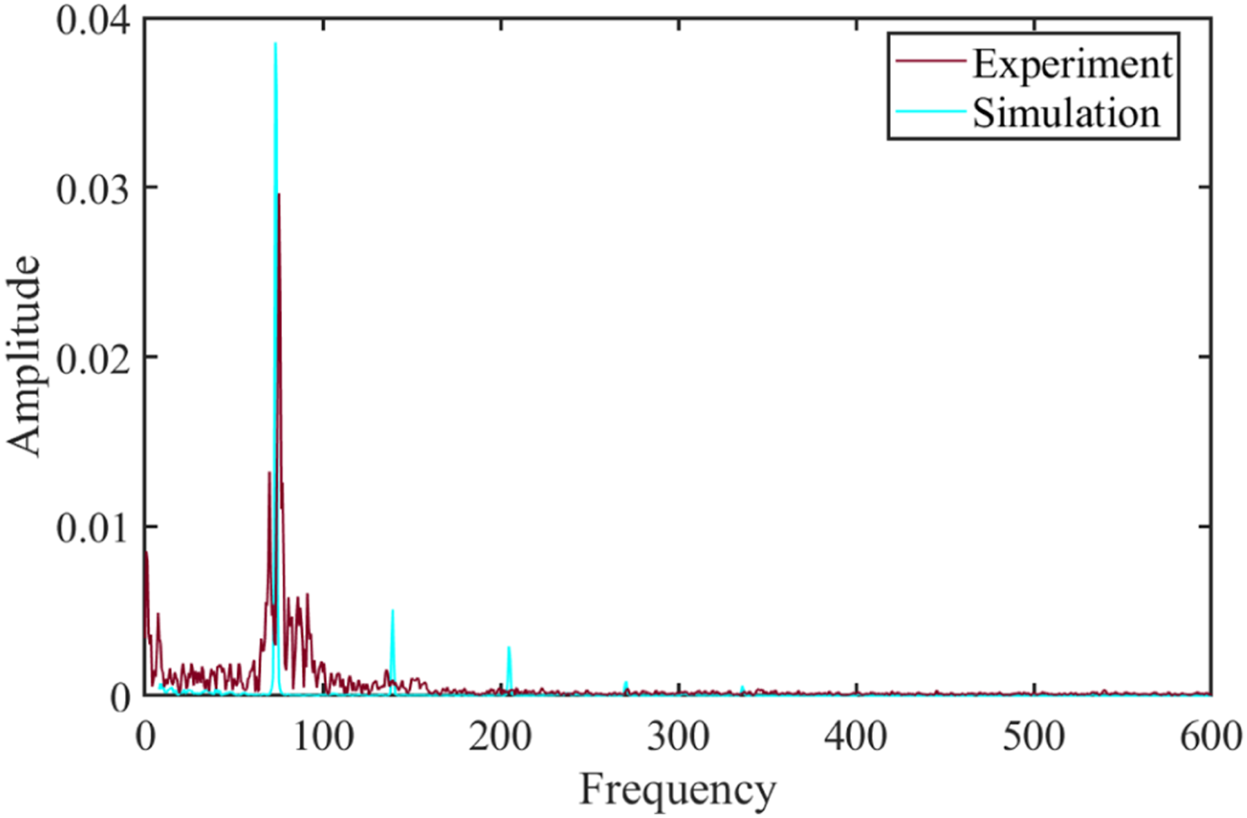
To quantify the agreement between simulation and experiment, the dominant frequency error and the dominant amplitude error were calculated. The dominant frequency error is 8.125%, and the dominant amplitude error is 23.099%. The differences can be ascribed primarily to two aspects. First, there are measurement uncertainties in the torque and angle sensors of the test rig, additional noise introduced during signal acquisition and processing, and manufacturing and installation errors of the mechanical components and assemblies. Second, the model idealises the gear tooth profiles, support conditions and other features, which introduces further deviations from the actual system. As these errors remain within an acceptable range, the observed consistency between the experimental and simulated spectral characteristics confirms the effectiveness of the proposed modelling approach and its ability to predict the dynamic behaviour of the DDR transmission system.
6. Conclusions
Conventional reducers are often limited in compactness, transmission ratio range, transmission efficiency and manufacturability. In this study, a new Double Differential Reducer with good manufacturability and a wide transmission ratio range is developed. Based on the established 21-degree-of-freedom dynamic model, the dynamic characteristics of the reducer are investigated, and the following conclusions can be drawn: (1) A new reducer architecture based on the double layer Less tooth differential transmission principle is proposed, which alleviates the contradiction between a wide transmission ratio range and a compact structural envelope. Within the same external envelope, this configuration theoretically enables an ultra-wide transmission ratio range from zero to positive infinity. The adopted structural design relaxes the manufacturing and assembly accuracy requirements of the reducer components. (2) A 21-degree-of-freedom nonlinear dynamic model of the Double Differential Reducer is formulated, in which the main nonlinear factors of the transmission system are taken into account. The model predicts that the nonlinear state of the transmission system follows a period-1–chaotic–period-1–period-2 sequence. (3) Experimental tests on a prototype using the dedicated reducer test bench show good agreement between the simulated and measured vibration responses, with errors of 8.125% in the amplitude of the main frequency component and 23.099% in the main frequency, thereby validating the proposed dynamic model. (4) Under the high-speed excitation of speeds above 10000 rpm, the transmission system exhibits stable single cycle vibration, which confirms its potential for high-speed applications.
This work proposes a novel transmission structure, develops and analyses the dynamic model of its transmission system, and validates the model experimentally. These results provide engineering reference for the development of new transmission schemes for robot joints and a theoretical basis for further study of the dynamic characteristics of Double Differential Reducers. The proposed transmission structure satisfies the relevant reducer standards and demonstrates the feasibility of the new Double Differential Reducer concept. However, as a new form of transmission, the present work still has limitations. The analysis is restricted to dynamic parameters under standard operating conditions, and other nonlinear effects remain to be incorporated. In addition, the connection between the two planet-gear structures is idealised as rigid, whereas in practice the finite connection stiffness can have a significant influence on the dynamic model and its predicted responses. Future work will extend the Double Differential Reducer model to include installation errors, manufacturing errors and connection stiffness, and the developed Double Differential Reducer will be integrated into a robotic arm or leg joint to evaluate the stability and reliability of the reducer under actual operating conditions.
Footnotes
Funding
The authors disclosed receipt of the following financial support for the research, authorship, and/or publication of this article: This work was supported by the National Key Research and Development Program of China under Grant 2024YFB3410400.
Declaration of conflicting interests
The authors declared no potential conflicts of interest with respect to the research, authorship, and/or publication of this article.