
Abstract
Purpose
Capsule endoscopy offers a minimally invasive approach to gastrointestinal (GI) diagnostics but is limited by passive propulsion, which restricts controllability and risks suboptimal visualisation in complex anatomical regions. This study aims to develop and validate advanced control strategies for the CAPSUBOT, a vibro-impact robotic active capsule endoscope, enabling precise navigation and sustained motion within the GI tract.
Methods
A two-degree-of-freedom (2-DOF) navigation system is implemented to control the relative motion of the inner mass with respect to the outer mass of the capsule. The capsule dynamics are mathematically modelled and formulated in the state-space domain. Linear Quadratic Regulator (LQR) and various Sliding Mode Controllers (SMC), including first-order SMC, second-order SMC, Integral SMC (ISMC), and Terminal SMC (TSMC), are designed and simulated using MATLAB/Simulink. Frictional forces and interaction effects are incorporated to emulate realistic operational conditions. The controllers’ performance in tracking desired trajectories is systematically evaluated, and the potential for optimisation of LQR weighting matrices using computational techniques such as artificial bee colony, genetic algorithm, particle swarm optimisation, and reinforcement learning is discussed.
Results
Simulation results demonstrate that both LQR and SMC controllers can effectively guide the CAPSUBOT along commanded trajectories. First-order SMC, ISMC, and TSMC exhibit particularly strong performance in achieving steady-state tracking of the inner mass position and velocity, whereas LQR offers improved trajectory tracking under nominal conditions. The SMC controllers show robustness against disturbances and system uncertainties, supporting their use for sustained in vivo motion. Some time delays are observed in the SMC responses, highlighting areas for further improvement.
Conclusion
This work establishes a framework for actively controlling a vibro-impact robotic capsule endoscope using LQR and SMC strategies, providing unified principles for the interaction of inner and outer capsule masses under feedback-controlled actuation. While the controllers demonstrate feasibility and robustness, limitations remain: SMC time delays and computational complexity in real-time implementation warrant further investigation. Future work will focus on integrating artificial intelligence-based reinforcement learning, neural networks, and fuzzy logic to develop faster, adaptive controllers. Overall, the study contributes both practical guidance for CAPSUBOT navigation and generalized control principles that may inform the design of other active capsule endoscopy systems.
Keywords
Introduction
GI tract comprises the oesophagus, stomach, intestine, and colon with a length of about 30 feet (Appleyard et al., 1 Kim et al., 2 ). Appleyard et al. 1 provided the first controlled evidence that wireless capsule endoscopy significantly outperforms push enteroscopy in detecting small-bowel lesions, establishing capsule endoscopy as a more sensitive and minimally invasive diagnostic modality. Kim et al. 2 introduced a novel earthworm-inspired locomotive mechanism using an impact-based piezo actuator that enables active propulsion in capsule endoscopes, addressing the diagnostic limitations inherent in passively propelled devices. In the 1950s, the GI tract was able to be examined using a Gastro-camera (Kusuda, 3 ). Wireless capsule endoscopes are novel diagnostic tools, which are utilised to comfortably investigate the entire GI tract as they have numerous benefits in comparison with the probe endoscopy, including being less invasive and more suitable due to the inflexible and large diameter of the endoscope, which is between 11 to 13 mm, this means it cannot access all the areas, including blind spots and regions which are complex and narrow, like the small bowel. However, there are some restrictions associated with these capsule endoscopes which are important to resolve. For instance, they do not have therapeutic abilities such as taking a biopsy, in which some works are in progress to resolve these issues. Also, capsule endoscopes can only collect passive pictures while being moved within the GI tract and cannot inflate the GI lumen which can prevent some damages from being detected. Furthermore, the processes of operating the capsule endoscopes and understanding the pictures could be time-consuming. Additionally, substances such as mucus and bile can cause unclear pictures to be collected (Koulaouzidis et al., 4 Appleyard et al., 1 Kim et al. 2 Zhang et al. 5 ). Koulaouzidis et al. 4 synthesised a decade of advancements in small-bowel capsule endoscopy, offering a structured, evidence-driven appraisal of its diagnostic performance, technological evolution, clinical challenges, and future research directions. Zhang et al. 5 contributed a magnetically driven capsule endoscope system that integrated positional tracking with rotational magnetic actuation, demonstrating through off-body intestinal experiments that a spiral-surfaced capsule can achieve controlled forward and backward locomotion under an externally generated rotating magnetic field. Chen et al. 6 presented a closed-loop magnetic actuation and localisation system in which embedded permanent magnets and external Helmholtz coils enable precise wireless propulsion and orientation control of capsule endoscopes, achieving real-time tracking accuracy within 3 mm and demonstrating a viable method for actively navigating GI capsules without onboard actuators. A magnetic field driven wireless capsule endoscope does not require the power supply to be connected to the magnet to move. In our system, a micromotor is the basis of the internal actuator, and the magnetic field is used as the external actuator. Ciuti et al. 7 provided a comprehensive review of robotic capsule endoscopy, outlining the state-of-the-art in locomotion, localisation, imaging, telemetry, powering, and therapeutic modules, and mapping the technological challenges and future directions required to advance capsule endoscopy from passive imaging devices to fully integrated diagnostic-therapeutic robotic platforms. The main challenge in wireless capsule endoscopy is power management, due to dimension restrictions and high power-consuming elements like LEDs. Van de Bruaene et al. 8 synthesised fifteen years of progress in small-bowel capsule endoscopy, offering an in-depth evaluation of technical evolution, clinical indications, complications, diagnostic performance, and future innovations including active locomotion, enhanced imaging, and therapeutic capabilities. Hosoe et al. 9 delivered a broad clinical review of capsule endoscopy across the entire digestive tract, detailing technological advances, diagnostic performance across organs (oesophagus, stomach, small bowel, colon), and emerging applications such as magnetically guided capsules and next-generation devices. Imaging capabilities regarding illumination, sensor features, and modality are very crucial characteristics which should be considered. Keuchel et al. 10 provided an updated, image-rich comprehensive reference on video capsule endoscopy, offering clinicians an extensive catalogue of normal and abnormal small-bowel findings alongside practical guidance on procedure preparation, interpretation, and integration with complementary imaging modalities. Additionally, a telemetry technique with a high data rate is important for high-resolution imaging. Than et al. 11 presented one of the most comprehensive surveys of localisation technologies for robotic capsule endoscopes, evaluating magnetic, electromagnetic, radio-frequency, optical, x-ray and hybrid systems, and identifying key limitations and research gaps toward achieving accurate real-time 6-degree-of-freedom tracking in clinical environments. Accurate localization techniques are used and are also critical. Review accomplished by Fakhr Abdollahi et al., 12 synthesised current advances in modelling, control strategies, and self-propulsion mechanism for remote-controlled capsule endoscopes, highlighting promising non-linear control techniques (e.g., Linear Quadratic Regulator and Sliding Mode Control) and vibro-impact two-mass dynamic models as foundations for next-generation actively steerable capsule endoscopes. Furthermore, wireless capsule endoscopes are either passive or active based on whether they contain non-controlled or controlled locomotion.
There are various limitations on both internal and external propulsion robots which should be tackled prior to being used in the field, in which their benefits and drawbacks could be briefly summarised. Valdastri et al. 13 introduced a novel lead screw/slot-follower mesoscale legged locomotion mechanism and demonstrated the first swallowable 12-legged endoscopic capsule robot, providing optimised gait control, miniaturised design, and validated ex vivo locomotion performance in compliant and slippery intestinal environments. The benefits of internal propulsion are the feasibility of precise position control and the ability to distend the lumen. Quirini et al. 14 provided the first in-vivo feasibility demonstration of an electromechanically actuated 8-legged endoscopic capsule, showing that legged locomotion can reliably propel a capsule through ex-vivo and in-vivo porcine colons, thereby validating leg-based self-locomotion as a promising alternative to conventional push endoscopy. Slawinski et al. 15 synthesised state-of-the-art advances in capsule mobility, magnetic actuation, localisation, therapeutics, and drug delivery, highlighting magnetic manipulation and proprioceptive sensing as the most promising pathways toward fully controllable, interventional, and clinically deployable robotic capsule endoscopes. The drawbacks of internal propulsion, on the other hand, are the requirements for higher power, the hazard of damaging the internal tissue, the difficulty to create a sealed capsule with legs, and the need to implement wireless power transmission for inchworm-like propulsion systems. Liu et al. 16 delivered a comprehensive taxonomy and comparative evaluation of active capsule locomotion mechanisms, including friction-based, hydrodynamic, magnetic, vibration-based, and hybrid systems, clarifying their performance trade-offs and design constraints while identifying key engineering requirements for next generation controllable capsule endoscopes. Rahman et al. 17 provided one of the first comprehensive evaluations of magnetic-assisted capsule endoscopy across multiple commercial systems, demonstrating that magnetic control can significantly improve manoeuvrability and visualisation of the upper GI tract while highlighting remaining limitations in sensitivity, especially for minor gastric lesions. The benefits of external propulsion are the lower requirement for power and the feasibility of designing a fast self-propelling, hermetically sealable capsule. Simi et al. 18 introduced the first hybrid locomotion capsule that integrates internal-leg-based actuation with external magnetic dragging, proving through in-vitro, ex-vivo, and in-vivo tests that combining both propulsion modes enables reliable movement through collapsed intestinal regions while maintaining a swallowable device architecture. Mahoney et al. 19 developed a generalised control framework that shows how a single rotating permanent magnet can generate a rotating magnetic field about any desired axis at any position in space, enabling fully controllable propulsion of untethered magnetic devices in lumens and removing previous geometric constraints on capsule actuation. 20 Whereas, the drawbacks of external propulsion include the fact that precise control may not be feasible, the impossibility to distend the lumen, the difficulty in eliminating the tissue over the capsule lens, the probability of the entire capsule getting trapped while in motion, and the complexity and cost of a bulky control system. Sume and Babiarz 21 developed a closed-loop PID-based control strategy optimised via particle swarm optimisation to accurately track the trajectory of a one-dimensional legless CAPSUBOT driven by internal-force/static-friction locomotion, demonstrating through simulation that the four-step motion profile enables stable periodic movement and effective velocity tracking. A closed-loop controller with a proportional–integral–derivative (PID) control law was proposed to be able to continuously control the motion of the CAPSUBOT. Alternate methods of optimising the PID controller were used in Mahmoudzadeh and Mojallali, 22 and Mahmoudzadeh et al. 23 Mahmoudzadeh and Mojallali 22 introduced a nonlinear-optimisation-based five-step motion strategy for legless CAPSUBOTs and shows, through comparative simulations, that the optimised force-time profiles significantly increase travel distance, reduce cycle time, and lower power consumption, enabling smaller capsule designs with improved clinical feasibility. Mahmoudzadeh et al. 23 developed a PID-based closed-loop control system for a CAPSUBOT and introduces a modified chaotic genetic algorithm to optimise controller gains, achieving improved tracking performance and faster convergence compared with conventional Genetic Algorithm- and Particle Swarm Optimisation-based tuning approaches. Huda et al. 24 proposed the first behaviour-based and piecewise trajectory-tracking framework for a 2-D underactuated planar CAPSUBOT, defining nine fundamental motion behaviours, a behaviour-set selection algorithm, and a partial-feedback linearisation scheme that together enable accurate simulation-based tracking of a complex planar trajectories. A behaviour-based control approach was proposed and validated for the trajectory tracking of an under-actuated planar capsule robot. Behvandi et al. 25 presented a novel 3-degree-of-freedom legless capsule capable of 2-D motion in viscous environments, introducing a four-stage angular-velocity motion profile, an EKF-based multisensory fusion method for accurate state estimation, and a state-feedback controller validated through experiments. A full-state feedback controller was proposed along with a non-linear extended Kalman Filter to control the CAPSUBOT. La et al. 26 provided an experimentally validated comparative analysis of pure-vibration and vibro-impact locomotion mechanisms under varying friction levels, demonstrating that pure-vibration systems achieve higher forward progression and consistent period-1 dynamics, while vibro-impact systems exhibit lower progression efficiency and complex behaviours including period-2 chaotic motions. Two different vibration-driven controllers were proposed and compared for their performance.
Other controllers, in particular Sliding Mode Control (SMC), have remarkable properties including tuning, easy implementation, accuracy, and robustness. SMC can control various plants such as Multiple-Input Multiple-Output (MIMO) systems, discrete-time systems, and nonlinear highly coupled uncertain systems (Nandam et al., 27 ). Nandam et al. 27 offered an extensive survey of sliding-mode and variable-structure control applications across industrial systems, such as robotics, electric drives, rolling mills, and spacecraft, highlighted SMC’s robustness to parameter variations and disturbances, while also discussed practical implementation challenges including chattering and hardware limitations. Moreover, SMC has various advantages including a high level of disturbance rejection, unrestricted dynamic response and not being sensitive to variations of the plant parameters (Utkin, 28 ). Utkin 28 work formalised the mathematical basis of SMC, introducing design procedures, invariance conditions, and order-reduction principles, and demonstrates their effectiveness through diverse electric-drive applications where SMC provides strong disturbance rejection, robustness, and simplified controller realisation. Thus, the main purpose of choosing SMC control technique for our research is due to its stability and robustness properties (Slotine, 29 ; Hung et al. 30 ; Utkin, 31 ). Hung et al. 30 consolidated the foundational theory, mathematical framework, and practical applications of variable-structure and SMC, detailing core properties such as robustness, invariance, and order reduction while also addressing challenges like chattering and outlining future research directions across linear and nonlinear systems. In contrast, Linear Quadratic Regulator (LQR) is an advanced optimal control method that has been commonly used within numerous manipulating processes because of its high precision within motion applications (Mohammed, 32 ). Fundamentally, this method aims for a compromise between a suitable control input and a stable performance (Mohammed and Abdulla 33 ), which is the reason behind choosing this controller in our work. Mohammad and Abdulla 33 developed an ABC-optimised fractional-order PID controller for DC-motor speed regulation and demonstrates, through simulation, that the FOPID-ABC approach achieves significantly faster rise time and settling time than conventional PID tuning, highlighting the superior robustness and dynamic performance gained through fractional-order control. Hence, LQR and SMC techniques are implemented on the DC servomotor in our research.
The focus of this paper is to design a control system for maintaining the capsule at a required position and/or velocity and moving it along the GI tract and keeping it in its three-dimensional surroundings by controlling the relative motion of the inner mass with respect to the outer mass of the capsule. The capsule can then be navigated by controlling its actuator. Mathematical analysis is then carried out on the technique to explain its dynamics and modelled in the representation of state space so that the state space model can be used to design the controller. The LQR method is used to design a servo-controller as it gives precise motions, and the SMC is implemented, with approximations and coupled with feedback linearization, for designing the vibration- or impact-driven sustained motion controller. The simulation of the control technique is achieved using MATLAB/SIMULINK for the controllers’ validation.
The contributions of this paper are as follows. This research developed the dynamic system model of the CAPSUBOT, by replacing the literature model with an electromagnetic motor. This is because the dynamic model is needed to apply the proposed control techniques into it. The system involves a seven-step movement procedure, proposed in literature, between the inner mass and the outer mass, which are the main components of our dynamic model. The evolved CAPSUBOT prototype of our research consists of the electromagnetic motor actuating the inner mass relative to the outer mass. It then presents the trajectory tracking algorithm for the CAPSUBOT, including the desired position and velocity trajectories of the inner mass, which in turn contributes to the desired position and velocity trajectories of the outer mass. Since this is a nonlinear model, approximations and linearization are applied to the system which is represented in the state-space form. Another contribution of this paper is the implementation the interaction model to the dynamic system model, by considering different factors such as environmental resistance, viscous resistance, and the Coulomb friction. The LQR and SMC are advanced control techniques have been applied in the contributions of this research. LQR is a control approach which is developed for the trajectory tracking control of the CAPSUBOT that is applied to the evolved CAPSUBOT prototype, in which the algorithm is then validated using simulation. The final contributions cover the development of the SMC approaches and its variations, including parameter adaptation, such as first-order SMC, second-order SMC, first-order Integral Sliding Mode Control (TSMC) and first-order Terminal Sliding Mode Control (TSMC), for the trajectory tracking control of the CAPSUBOT. All these SMC forms are robust control strategies which are developed in order to come up with the most suitable control technique for the CAPSUBOT, by comparing which methods follow the desired trajectories the closest and reach the steady state the quickest. These developed control strategies are then applied to the evolved CAPSUBOT prototype, and the algorithm is validated using simulation. Additionally, the Lyapunov function is used to confirm the stability of the designed control techniques. Hence, the true contributions and innovations of this paper lie in the fact that, to date, no previous work has integrated LQR and SMC, implemented a literature interaction model, and applied these to a vibro-impact robotic active capsule endoscope featuring an electromagnetic motor and a two-mass system.
Dynamic modelling of vibro-impact capsules (CAPSUBOT)
Liu et al. 34 proposed a seven-step motion strategy and associated trajectory-profile design for a legless CAPSUBOT, and rigorously evaluates three control techniques, open-loop, closed-loop, partial feedback linearisation, and a simple switch control, showing that closed-loop control achieves accurate tracking while the switch control improves robustness and velocity despite implementation simplicity. They presented the dynamics of the capsule, involving an outer mass (M) and an inner mass (m), with x1 and x2 as their translational positions, respectively. The internal propulsion between the outer mass and the inner mass is the basis for the driving mechanism of the capsule. A servomotor is used to produce the propulsion force in this model, which functions between the inner mass and the outer mass (capsule robot shell).
This aim is to drive the capsule endoscope in the required direction. Let the coordinate origin be the centre of the outer mass. Also, µ1k is the kinetic friction coefficient between the environment and the outer mass. Moreover, µ2k is the kinetic friction coefficient between the outer mass and the inner mass. Furthermore, the initial position of the inner mass is ‘a’ and the acceleration due to gravity is g. In addition, the propulsion or control force between the inner mass and the shell is u.
The dynamics of the CAPSUBOT may be expressed in terms of two equations for the motion of the outer and inner masses as,


Equation (3) is formed by combining Equation (1) and Equation (2) together:

Equation (4) represents the second-order state space form of Equation (2) and Equation (3):


External forward motion of the capsule under the action of an internal impulse
Considering the capsule response under the action of an impulsive force it may be observed from equations (1) and (2) the forces on the two masses are equal and opposite. However, the the friction forces on the two masses are not the same. As the masses are also not equal, it can be seen that under the action of an impulsive force on the inner mass, both masses will respond with a sustained motion, albeit of small magnitude, in the same direction. Assuming a jerk (a small change in the acceleration) is applied to the inner mass in equations (2), and assuming that the acceleration of the outer mass is small, it follows that the jerk on the inner mass results in a small but sustained motion of the outer mass. Thus, applying a continuous stream of jerk inputs or impulsive control forces to the inner mass results in a continuous motion of the outer mass.
Environmental interaction model within the intestinal tract
The incomplete interaction model between the capsule robot and the intestine is a major factor leading to poor controllability and the failure to achieve fully automated checks. While several researchers have worked on modelling the intestinal environment, no accurate mathematical model existed to define the interaction force between the intestine and the capsule robot until Zhang et al. 35 made significant improvements to the interaction model. Zhang et al. 35 developed and experimentally validated a quantitative velocity-dependent friction model for capsule robots moving inside the intestine, integrating Coulomb, viscous, and viscoelastic environmental resistance components, and showing strong predictive accuracy at low velocities relevant to medical capsule locomotion. The subsequent work by the same group Zhang et al. 36 built upon Zhang et al. 35 Zhang et al. 36 proposed a nonlinear viscoelastic interaction model that characterises the combined environmental, viscous, and Coulomb forces acting on capsule robots in the intestine, with parameter identification across different velocities and experimental verification demonstrating its effectiveness for optimising capsule robot control strategies. What sets their research apart from earlier efforts is that their model not only provides a reasonable description of the interaction force but has also been validated through experimental verification, representing an important step toward perfecting the interaction model. Their achievement is expected to enhance the interaction model and optimize the control method of CAPSUBOT, particularly for the vibro-impact CAPSUBOT. Therefore, their literature interaction model was deemed the most suitable for implementation in our CAPSUBOT model.
In the x-direction interaction force is crucial for the motion of the capsule and it is modelled as the sum of coulomb friction force Fc, viscous resistance Fv, and environmental resistance Fe:
The intestinal hoop stress mainly causes the contact force. The expression for the relationship between the hoop stress τθ(x) and pressure P(x) is:
Magnetic actuation of the CAPSUBOT
The passive motion approach of the CAPSUBOTs restricts their application as a commercial diagnosis device within hospitals. Thus, various control approaches have been developed for the CAPSUBOTs. Several models have been proposed for the magnetic actuation of the CAPSUBOT (Zhang et al. 36 ; Yatchev et al. 37 ; Gajak and Awrejcewicz 38 ). Yatchev et al. 37 presented a decoupled finite-element-based dynamic simulation framework for a long-stroke permanent-magnet linear actuator and validated the model experimentally, demonstrating that the method can accurately predict electromagnetic force, current, and displacement behaviour despite the absence of eddy-current effects. Gajak and Awrejcewicz 38 developed two high-fidelity nonlinear mathematical models of a coreless three-phase linear electromagnetic motor, one using a sinusoidal magnetic-field approximation and the other using an elliptic theta-function representation, and validated both experimentally, demonstrating that the theta-based model provides higher accuracy while the sine-based model offers faster computation for practical control applications. As presented by Mohammed and Abdulla, 33 magnetic locomotion is suggested by numerous researchers for wirelessly moving the CAPSUBOTS within the GI tract, because the body of the patient has little magnetic permeability and has no influence on the magnetic field distribution (Chen et al. 6 ).
A permanent magnet is used to generate a magnetic field. An electrically driven armature coil is used to generate the electromagnetic actuation force, which is assumed to be proportional to the armature current. The mathematical model of the actuator is expressed in terms of an electrical circuit model, and a model for the actuation force given by,

Ignoring the inductance L, 
The actuator stem velocity ω responds directly to the applied voltage.
In the case of the CAPSUBOT, the control input force is directly proportional to the armature current. In this case, actuator stem velocity is given by the velocity of the inner mass relative to the outer mass, 
Optimal control of the CAPSUBOT
A full-state feedback controller can be designed for a system, but that could lead to some issues, such as control saturation and the inability to measure all states. The LQR and Linear Quadratic Gaussian methodologies has many advantages for designing regulators that track a set point.
The control system performance can be measured by a quadratic cost function to design a control system for a linear dynamic system as outlined by Bryson and Ho. 39 This is done by setting up the optimisation for designing a linear quadratic regulator (LQR) using the m-file provided in MATLAB. Bryson and Ho 39 provided the theoretical basis and computational methods for optimal control, presenting systematic treatments of variational calculus, dynamic programming, optimal feedback, numerical optimisation, and stochastic control, thereby establishing a cornerstone framework for modern optimal-control design in dynamic systems. The dynamic system has multiple states x(t) and multiple controls u(t) and is expressed as a standard state space model.
The problem reduces to finding an optimum negative feedback control law to control the relative motion of the inner mass with respect to the outer mass of the capsule in the form,
The solution to the problem is a full-state feedback controller, and the control law is defined in terms of the solution to an algebraic Riccati equation.
In order to model the dynamic system for the synthesis of the LQR, some assumptions have been made. These assumptions are that the friction is very small and can be neglected in deriving the controller. Consequently, the equations of motion are expressed as a standard set of first order equations in state space. The performance indices Q and R, which are chosen following Bryson’s rule. 39
The optimal full state feedback gain is found by solving an algebraic Riccati equation using the MATLAB function lqr.m. Figure 1 illustrates the position and velocity of the outer mass and the inner mass, respectively, with the desired profiles. The LQR controller tracks the desired velocity and position trajectories of the inner mass, as shown in Figure 1. Comparison of the simulation results obtained from the closed-loop control system by the LQR controller using MATLAB with the desired inner mass position and velocity. Top, (a) M-position (m) (outer mass) vs time (s) graph. Second from top, (b) m-position (m) (inner mass) vs time (s) graph. Third from top, (c) M-velocity (m/s) (outer mass) vs time (s) graph. Bottom, (d) m-velocity (m/s) (inner mass) vs time (s) graph.
Sliding mode control (SMC) of the CAPSUBOT
SMC is an established control technique, capable of easy tuning and implementation, with accuracy, and robustness (Sabanovic 40 ; Hung et al. 30 ; Utkin et al. 41 ). Utkin et al. 41 provided a comprehensive and application-oriented review of SMC for electromechanical systems, emphasising practical implementation, common design challenges, and illustrative simulation examples that guide engineers in applying sliding mode methods effectively. The SMC is designed by specifying the sliding surface and the control law to switch to the sliding surface. The trajectory is directed toward the area bounded by the boundary layers using the aid of the control switch. The trajectory progressively travels to the sliding surface and progresses to the target point with the control of the sliding conditions (Lin et al. 42 ). Lin et al. 42 introduced a generalised Proportional-Integral Sliding Mode Control framework that offers enhanced robustness, simplified parameter tuning, and improved performance over conventional SMC, and validates the approach through both simulation and real-time implementation on a nonlinear two-wheel vehicle balancing system. Furthermore, the Lyapunov stability principle is used, so that numerous conditions of globally asymptotically stable are achieved for the movement dynamics of the sliding mode (Tong et al., 43 ). Tong et al. 43 developed a novel SMC strategy for nonlinear systems with time-varying delays and disturbances by formulating an integral sliding surface, removing restrictive assumptions on delay derivatives, and establishing less conservative stability conditions supported by both normal and adaptive SMC laws. Hence, this structured approach was implemented in our paper to design the SMC for the CAPSUBOT.
In this paper the methodology of feedback linearization was combined with an approximation of the nonlinearity in the equations of motion to develop the SMC laws. It must be said at this stage there several alternatives available. He’s frequency domain formulation (He 44 ) as well his variational approach (He 45 ) are indeed feasible alternatives. In fact the transformational approaches (He 46 ) and the differential equation-driven intelligent control strategies discussed by Cheng, Luo, Zhong, et al., 47 provide several viable alternatives.
Tuning the sliding mode control parameters in a simulation involves a systematic approach to optimize system performance. To begin with, the desired performance criteria and system dynamics are defined, including the system’s stability and response time. Next, a simulation tool is used to model the system and implement the sliding mode controller with initial parameters. Firstly, the sliding surface parameters are adjusted, which influence how the system trajectory approaches and remains on the sliding surface. Also, the gain parameters are tuned to balance between robustness and control performance, ensuring that the system can handle uncertainties and disturbances while achieving the desired response. Then, simulations are iteratively run, and performance metrics are analysed such as overshoot, settling time, and robustness to disturbances. Afterwards, optimization techniques or trial-and-error adjustments are used to refine the parameters, aiming to meet the performance criteria while minimizing chattering and ensuring system stability. Lastly, the results and adjustments are recorded to identify the optimal parameter set for the CAPSUBOT.
Transformation of state representations
The equations of motion of the CAPSUBOT in state space are as follows,


Following Vepa,
48
the equations are transformed by feedback linearization, by applying the transformation,


The input v0 in the last of Equations (17), is defined by,
Hence, the complete dynamics in the original states are,


First-order sliding mode control
Once the feedback linearization is applied, the SMC control methods are carried out. The SMC control law includes the equivalent
SMC involves two phases, the reaching and sliding phases, in which the system reaches the desired sliding surface during the reaching phase. The following procedure is for the first-order system, in which its sliding variable 
Next, since 
First-order SMC deals with the chattering phenomena when an oscillatory movement happens nearby the sliding manifold. Next, to achieve the control input, the sliding surface is placed at 


Then, the derivation of the sliding surface is achieved by placing the states’ values and driving the time derivative to zero. Therefore,
Also,

Thus the equation of motion on the sliding surface is,

The time derivative of V is required to satisfy the inequality given by,
Thus it follows that the sliding variable Simulation results obtained from the first-order control system by the SMC controller. Top, (a) M-position (m) vs time (s) graph. Second top, (b) m-position (m) (inner mass) vs time (s) graph. Third top, (c) M-velocity (m/s) vs time (s) graph. Bottom, (d) m-velocity (m/s) vs time (s) graph.
First-order integral sliding mode control
Utkin and Shi
49
introduced the ISMC design, a major advancement in variable-structure control that eliminates the reaching phase, guarantees full-trajectory robustness against uncertainties, and provides a generalised formulation applicable to robotics, electric drives, and nonlinear systems. The standard strategies for the sliding mode design are different to ISMC, and the only variation is the integral format of the error term as a substitute for the primary error term. Baik et al.
50
proposed a robust nonlinear speed-control scheme for Permanent Magnet Synchronous Motors by driving a quasi-linearised model and designing a boundary-layer integral sliding mode controller that significantly improves robustness to parameter variations and measurement errors, validated through Digital Signal Processor-based experimental results. They developed an ISMC with one discrete boundary surface to enhance the responses of the controller and reduce the chattering. In the case of the ISMC, its sliding variable Simulation results achieved from the first-order control system by the ISMC controller. Top, (a) M-position (m) vs time (s) graph. Second top, (b) m-position (m) vs time (s) graph. Third top, (c) M-velocity (m/s) vs time (s) graph. Bottom, (d) m-velocity (m/s) vs time (s) graph.
First-order terminal sliding mode control
Within the standard SMC, the state convergence is in infinite time, whereas the convergence of the state within the TSMC is in finite time. This mode designs the precise sliding surface, and the control law aims to keep the system on the stated surface. For designing the first-order TSMC system, sliding variable Comparison of the simulation results from the LQR and SMC approaches, including first-order SMC, ISMC and TSMC, and the desired inner mass position and velocity profiles. Top, (a) the outer mass position versus the time graph. Second top, (b) inner mass position versus time graph. Third top, (c) outer mass velocity versus time graph. Bottom, (d) inner mass velocity versus time graph.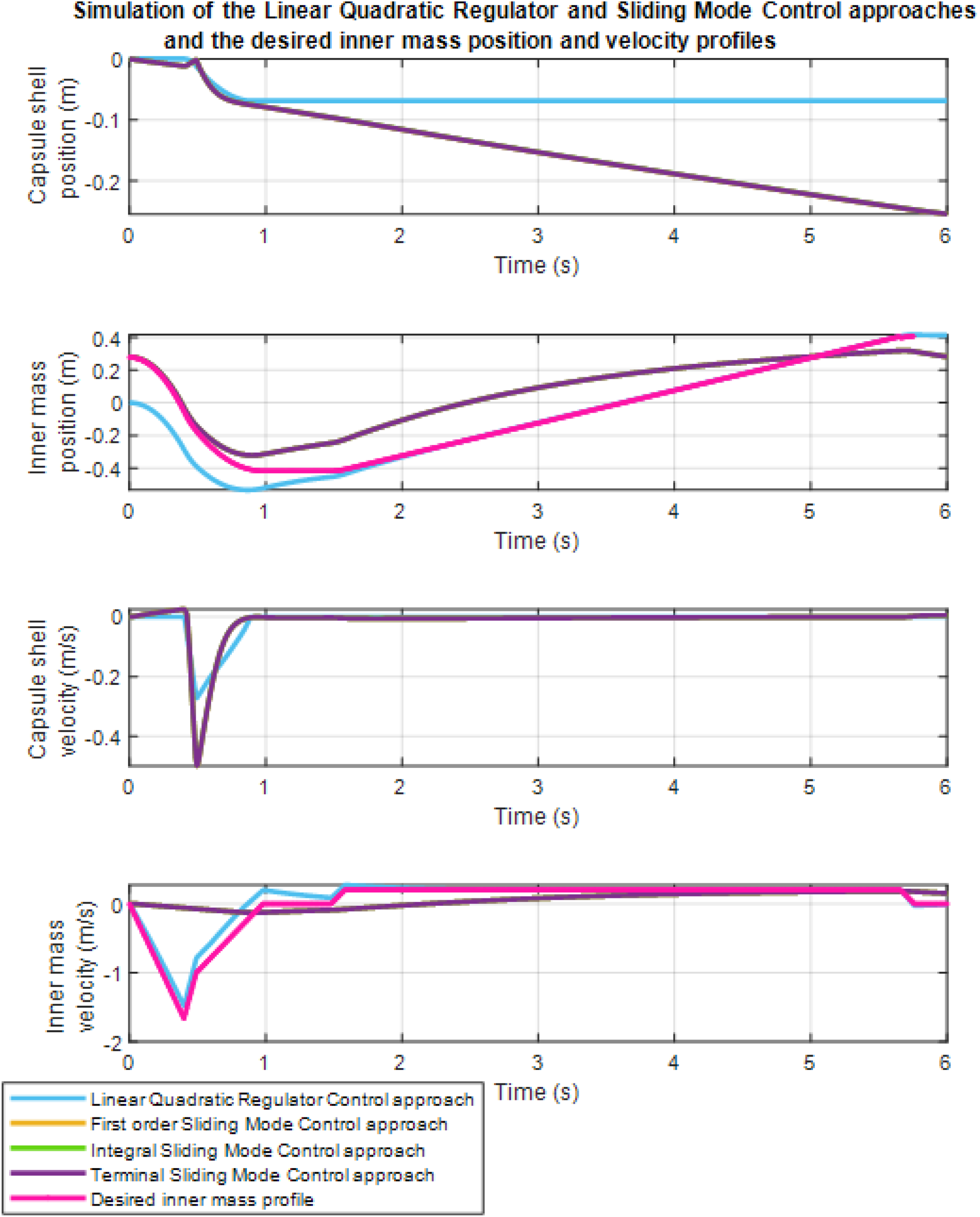
Higher order and adaptive SMC of the CAPSUBOT
Higher-order sliding mode control (HOSMC) is a sophisticated control strategy that enhances the performance of traditional sliding mode control by addressing issues like chattering and improving robustness. Implementing a HOSMC involves designing a control law that not only drives the system states to a sliding manifold but also ensures that the system’s higher-order derivatives of the sliding variable remain zero. To implement HOSMC, a higher-order sliding surface is designed that extends the classical sliding surface to account for derivatives of the sliding variable. To start with, the system dynamics and desired sliding surface are defined, which typically involves higher-order time derivatives of the tracking error. Then, a control law is developed that ensures the system state converges to this sliding surface while also ensuring that the higher-order sliding dynamics are robust to disturbances and uncertainties. The control law is implemented by designing a switching function that drives the system state towards the sliding surface and maintains it there, adjusting the controller gain to manage the trade-off between robustness and performance. Finally, the HOSMC is validated by simulating its behaviour in different scenarios to ensure that it achieves the desired robustness and reduces chattering compared to lower-order sliding mode controllers.
Alternately an adaptive approach was also considered, particularly since µ1k the kinetic friction coefficient between the environment and the outer mass, is never really known accurately. Only the parameter µ1k is assumed to be uncertain and was adaptively updated. The positive definite candidate Lyapunov function, now not only includes a quadratic function of the sliding variable
As implementing the second-order SMC avoids chattering, it is also applied to the second-order system for the CAPSUBOT, explained next. For the second-order SMC, the sliding variable
The interaction model and the frictional forces are also applied to the simulation of the closed loop system with the adaptive first-order SMC system, where the simulation results are displayed in Figure 5. Simulation results obtained with the Adaptive First-order SMC system. Top, (a) Outer mass (M)-position (m) vs time (s) graph. Second top, (b) Inner mass (m)-position (m) vs time (s) graph. Third top, (c) M-velocity (m/s) vs time (s) graph. Bottom, (d) m-velocity (m/s) vs time (s) graph.
Application and validation of the controllers
Feng et al., 51 Yan et al., 52 Han et al., 53 Hanscom and Cave, 54 Liu et al., 55 and Zhang et al. 56 have performed extensive simulation studies involving the motion of a capsule robot within the GI tract. Feng et al. 51 provided one of the first comprehensive dynamic simulations of capsule motion in Poiseuille flow, revealing the hydrodynamic mechanisms of lift-off and steady flying, and distinguishing the roles of lubrication and inertial forces in capsule levitation within pipelines. Yan et al. 52 contributed a combined Computational Fluid Dynamics-driven geometric optimisation and experimental validation of a vibro-impact self-propelled capsule, demonstrating significant reduction in drag and lift coefficients and confirming improved bidirectional mobility for autonomous pipeline inspection. Han et al. 53 introduced a novel inchworm-like intestinal micro-robot that integrates a two-layer expanding mechanism and a self-locking telescoping system, providing one of the first actively locomoted, bidirectional, and stable anchoring robotic platforms capable of safely navigating and expanding intestinal tissue for enhanced diagnostic inspection. Hanscom and Cave 54 reviewed a summary of recent advances in capsule endoscopy imaging, AI-based diagnostics, active locomotion, and localisation technologies, demonstrating how these developments expand clinical applications of capsule robots across the GI tract. Liu et al. 55 synthesised mathematical, biomechanical, computational, and experimental models of the small intestine, identifying limitations in current test platforms and outlining research directions essential for designing next-generation controllable capsule endoscopy systems. Zhang et al. 56 developed and experimentally validated a vibro-impact, electromagnetically driven capsule endoscopy prototype, providing analytical, numerical, and empirical evidence that external electromagnetic excitation can enable controllable small-bowel locomotion with optimised propulsion performance. Early models of these involved the motion of a capsule in a fluid pipeline, while later models involved extensive simulation of both the environment, as well the motion of the capsule in a multi-dimensional space.
In this paper, as a validation of the controller designs, two examples of CAPSUBOT trajectories would be simulated in a SIMULINK environment. In the first case, an LQR control law is used to track the required velocity trajectory of the inner mass in the capsule. The SIMULINK diagram for this case is shown in Figure 6(a). In the second case, the SMC is used to generate a sustained steady motion of the CAPSUBOT within a model of the GI tract. The SIMULINK diagram for this case is shown in Figure 6(b). The position and velocity response of the SIMULINK diagram with the LQR controller, in Figure 6(a), are shown in Figures 7 and 8, respectively. The advantage of using the SIMULINK approach is seen here since it is now possible to vary the intestinal friction as desired. The variation in the friction could result from a change in the strain condition of the colon. The result of varying the friction is shown in Figure 9. SIMULINK diagram of a CAPSUBOT with (a) a LQR type controller to track the required velocity profile and (b) with a SMC type controller to generate sustained motion in the GI tract. Velocity response of the inner mass in SIMULINK scope shown in Figure 6(a) (with LQR). Sustained position response of the outer mass in SIMULINK scope shown in Figure 6(b) (with SMC). Comparison between the LQR simulation result of the inner mass position versus time response obtained using SIMULINK with low and high friction, to model the variation in the colon strain condition.


Figure 10 shows the sustained simulated response of the CAPSUBOT in two dimensions, based on the SIMULINK simulation, shown in Figure 6(b), of the CAPSUBOT motion with the SMC. The response demonstration of the X-Y plotter in the simulation diagram, shown in Figure 6(b), of the CAPSUBOT motion in the GI tract with the SMC.
Discussion and conclusion
This study developed controlled actuation strategies for the CAPSUBOT using Linear Quadratic Regulator (LQR) and Sliding Mode Control (SMC) systems, focusing on regulating the relative motion of the inner mass with respect to the outer mass. A two-degree-of-freedom navigation technique was implemented to guide the capsule inside the gastrointestinal (GI) tract, with the control system dynamics formulated mathematically in the state-space domain. The first-order SMC, second-order SMC, integral SMC (ISMC), terminal SMC (TSMC), and LQR controllers were designed and validated through MATLAB simulations, incorporating interaction models and frictional forces.
The results indicate that all controllers can successfully track the desired trajectories, enabling effective navigation of the CAPSUBOT within the GI tract. Among the SMC variants, the first-order SMC, ISMC, and TSMC demonstrated similar performance in achieving steady-state responses for inner mass position and velocity, supporting their suitability for active navigation. The LQR controller provided accurate trajectory tracking and could be further optimised using computer-aided techniques such as artificial bee colony, genetic algorithms, particle swarm optimisation, and reinforcement learning-based approaches.
Despite these promising outcomes, several limitations must be acknowledged. The simulations revealed a time delay in the SMC responses, which may affect real-time performance and requires further investigation. Additionally, the current study focused on simplified two-mass dynamics under idealised conditions, which may not fully capture the complex physiological environment of the GI tract, including variable peristaltic forces, anatomical anomalies, and heterogeneous frictional interactions. Future work should incorporate more realistic in vivo conditions and consider adaptive or AI-based controllers, such as reinforcement learning, neural networks, or fuzzy logic, to enhance response speed, robustness, and autonomy of the CAPSUBOT.
Importantly, this research also contributes to the extraction of unified principles underlying vibro-impact active capsule locomotion. By analysing the relative dynamics between the inner and outer masses under different control strategies, common patterns of sustained motion and trajectory tracking emerge, offering insights that can inform the design of generalised control frameworks for similar robotic capsules. These principles provide a foundation for translating simulation-based findings into practical navigation strategies applicable to various active capsule systems.
In conclusion, the proposed LQR and SMC controllers demonstrate effective trajectory tracking and sustained locomotion for the CAPSUBOT, providing a viable pathway toward active, controllable capsule endoscopy. Addressing the identified limitations and leveraging unified control principles will be essential for future development of robust, clinically applicable robotic capsule systems.
Footnotes
Funding
The authors received no financial support for the research, authorship, and/or publication of this article.
Declaration of conflicting interests
The authors declared no potential conflicts of interest with respect to the research, authorship, and/or publication of this article.
Data Availability Statement
No new data were created or analysed in this study. Data sharing is not applicable to this article.