
Abstract
In this study, an enhanced version of the Bat Optimization Algorithm (BOA) is developed by incorporating the Balloon Effect (BE), to improve adaptive control performance in electrical systems. Unlike the conventional BOA, the proposed method dynamically adjusts its parameters based on system variations, increasing its robustness against disturbances and uncertainties. The key novelty of this work lies in utilizing BE to enable real-time adaptability, eliminating the need for fixed parameter tuning. The effectiveness of the proposed approach is validated through simulations and experimental tests, demonstrating superior performance in DC motor position control and load frequency control, compared to traditional methods.
Keywords
Introduction
Background
Amid growing concerns over the environmental impact of conventional power generation methods, particularly fossil fuels,1,2 there is a concerted effort among researchers to explore cleaner and renewable energy sources (RESs), like wind energy and solar photovoltaic (PV).3–6 These RESs, being both user-friendly and cost-effective, have garnered significant interest. However, their intermittent nature makes relying solely on them impractical. To address this, controllable Energy Storage Technologies (ESTs) are often paired with RESs. The shift from thermal energy to renewable sources is expected to continue, with a particular focus on microgrid (μG) frequency control, due to its critical role in ensuring power balance and system stability.7–10 Achieving robust and versatile performance under various conditions is paramount in isolated μGs. Load Frequency Control (LFC) plays a crucial role in maintaining power balance within acceptable limits, 11 especially in off-grid μGs, where methods like energy sources, synthetic virtual inertia, and ESTs are employed. Also, DC motors are popular due to their numerous advantages. They provide high starting torque, making them perfect for quick acceleration and lifting heavy loads. They offer a wide speed range and can be easily controlled for precise speed and position control. Their simple and compact design allows for easy installation and maintenance. 12 DC motors are extensively utilized in fields like robotics, industrial automation, electric vehicles, and renewable energy systems.13,14 They are commonly found in conveyor belts, pumps, fans, and compressors. Their high torque capability makes them suitable for driving heavy machinery and vehicles. 12 Additionally, DC motors are essential in renewable energy systems, such as wind turbines and solar panels, where they facilitate the conversion of mechanical energy into electrical energy.15,16 Because of its efficacy and simplicity, the PID controller is widely utilized in a variety of sectors.17–19 It has the potential to enhance steady-state and transient performance as well. 20 PID was utilized effectively in various applications, especially in the control of DC motors.21,22
PID (Proportional-Integral-Derivative) controllers can be tuned online via several methods, as follows, due to the unsuitability of fixed-parameter controllers based on nominal operating points. There are several examples of tuning PID controllers online that provide helpful insights and references for understanding this process. These examples involve different techniques and methods to achieve optimal control performance for a variety of systems. Here are a few prominent ones: • Zeigler–Nichols Method: This is one of the most common and widely used methods for PID tuning. It involves step response analysis, specifically relay feedback. The Ziegler–Nichols method determines controller parameters based on the ultimate gain and oscillation period of the system’s response.
23
• Lambda Tuning: A tuning method that is designed to achieve certain performance criteria by tuning the controller parameters under consideration of process time constant and delay.
24
• Tyreus–Luyben Approach: This approach adds a frequency response analysis to the Ziegler–Nichols method. It outperforms the classic ISE (integral of the squared error) criterion by incorporating the integral of the absolute value of the error (IAE).
25
• Improved Bacterial Foraging Optimization (BFO): To compute optimum settings for the PID controller, improved BFO techniques have been developed.26,27
The possibility to tune the PID settings online is offered. To optimize the PID parameters for the continuous stirred tank reactor application, genetic algorithms were applied as in.28–30 Furthermore, as explained in, 31 for switched stochastic nonlinear pure-feedback non-lower triangular systems, neural networks play an essential role in solving the adaptive control problem. Although these controllers have shown great results, there is still room to investigate and create new algorithms that can improve the performance of adaptive controllers. BOA has gained popularity due to its simplicity and effectiveness in solving various optimization problems. 32 It has been successfully applied in different domains, including engineering, finance, scheduling, and image processing. In engineering, 33 BOA has been utilized for parameter optimization in various systems, such as power systems, 34 control systems,35–37 and communication networks.38–40 In finance, BOA has been employed for portfolio optimization, stock market analysis, and credit scoring.41,42 In scheduling, BOA has been used for job scheduling, task assignment, and resource allocation. 43 In image processing, BOA has been applied to image segmentation, clustering, and feature selection.44,45
Furthermore, the goal of BE is also to enhance the controller’s ability to manage system challenges, such as load disruptions and unpredictability in system characteristics, by fine-tuning the controller’s settings using optimization techniques. Both the Water Cycle Algorithm (WCA) for adaptive position control of a DC motor (explained in 47 ) and the Electro Search Algorithm for adaptive load frequency control have this feature included. The increasing complexity of modern electrical systems, such as DC motor control and smart microgrid frequency regulation, demands more robust and adaptive optimization techniques. Traditional optimization algorithms, including the Bat Optimization Algorithm (BOA), often rely on fixed parameter tuning, which limits their ability to adapt to real-time system variations and external disturbances. This limitation results in reduced control performance, longer settling times, and lower resilience to dynamic changes. To address this issue, this study proposes an enhanced BOA incorporating the Balloon Effect (BE), allowing real-time adaptability and improved disturbance rejection. By dynamically adjusting optimization parameters, the proposed BOA+BE method offers a significant improvement over conventional BOA, ensuring better stability and performance in electrical control applications.
The effectiveness of an optimization algorithm is best demonstrated through its application in diverse and practical control problems. In this study, two critical case studies are selected to evaluate the proposed BOA+BE method: DC motor position control and microgrid frequency regulation. These applications are not only fundamental in control engineering but also highly relevant in industrial and power system domains. DC motor position control is essential in robotics, manufacturing, and automation, where achieving fast response, minimal overshoot, and precise tracking is crucial for operational efficiency. Meanwhile, microgrid frequency regulation is a key challenge in modern power systems, particularly with the integration of renewable energy sources, which introduce fluctuations and uncertainties in generation and load demand. Traditional control methods often struggle to maintain system stability under such conditions. By applying BOA+BE to these two distinct yet significant control problems, this study highlights the algorithm’s ability to enhance adaptability, improve transient response, and maintain robustness under dynamic operating conditions. The results obtained not only validate the superiority of BOA+BE over conventional methods, but also pave the way for its application in more complex and large-scale control systems, such as multi-machine power grids, industrial process control, and autonomous systems.
Problem analysis
To solve the adaptive control issue, numerous optimization techniques are applied, each with its own methodology. Certain strategies are used to update the neural network or fuzzy controllers’ parameters with the objective function depending on the error values of the controlled variables, as evidenced in.48,49 In such cases, the objective function relies on the error value of the controlled variable. Additionally, there have been attempts to directly employ optimization techniques for parameter tuning of adaptive controllers, as proposed in.50,51 However, these attempts rely on Time response variables like overshoot, rising time, and settling time to construct the objective function (e.g., J min = ∑(M p +T r +T s )This approach suffers from a weakness, as M p , T s , and T r are functions of the nominal system parameter values, which becomes problematic for time-variant systems. A recent solution to this issue is the introduction of a modification known as balloon effect.46,47 The Balloon Effect (BE) facilitates dynamic interaction between the objective function and newly updated parameter values, adapting to system variations in real time. By incorporating BE adjustments, fundamental optimization algorithms can efficiently fine-tune control parameters across various real-time and industrial applications, including temperature regulation, motor control, and beyond.
Contribution
This study presents an enhanced Bat Optimization Algorithm (BOA), incorporating the Balloon Effect (BE) to improve adaptive control performance in electrical systems. The proposed approach is applied in two key control applications: • Position control of a DC motor-driven cart using a Position-Velocity (PV) controller. The BOA is utilized to optimize the PV controller gains, ensuring precise motion control. • Adaptive Load Frequency Control (LFC) in a smart microgrid (μG). The enhanced BOA dynamically adjusts frequency regulation parameters to mitigate fluctuations caused by varying loads and system uncertainties.
Initially, PV gains are tuned using the conventional BOA, which optimizes the parameters based on a predefined objective function (OF) aimed at minimizing settling time, overshoot, and rise time. While this method produces promising results, it struggles to maintain optimal performance under external disturbances or internal parameter variations. This limitation arises because the objective function is formulated based on a nominal system transfer function Go(S), which does not account for dynamic system variations.
To overcome this challenge, the Balloon Effect (BE) is introduced, allowing the BOA to dynamically adjust its parameters in real-time, significantly improving its adaptability to changing system conditions. Unlike conventional BOA, which relies on fixed parameter tuning, the proposed method enables continuous self-adaptation, leading to faster response times, improved robustness against disturbances, and enhanced overall control stability
Contributions of This Paper: • This study introduces a novel enhancement called BE to improve the adaptive tuning of controller gain parameters in optimization techniques, specifically the Bat Optimization Algorithm (BOA). • The proposed modification is tailored for electrical system applications, including adaptive frequency control in microgrids and adaptive position control of DC motors, where precise parameter tuning is essential for optimal performance. • The developed control method effectively addresses system uncertainties and disturbances, enhancing overall stability and efficiency. • To the best of the authors’ knowledge, this is the first integration of the Bat Algorithm with BE for position tuning of a controller in a cart powered by a direct current motor, marking a significant advancement in adaptive control strategies.
Bat Algorithm (BOA)
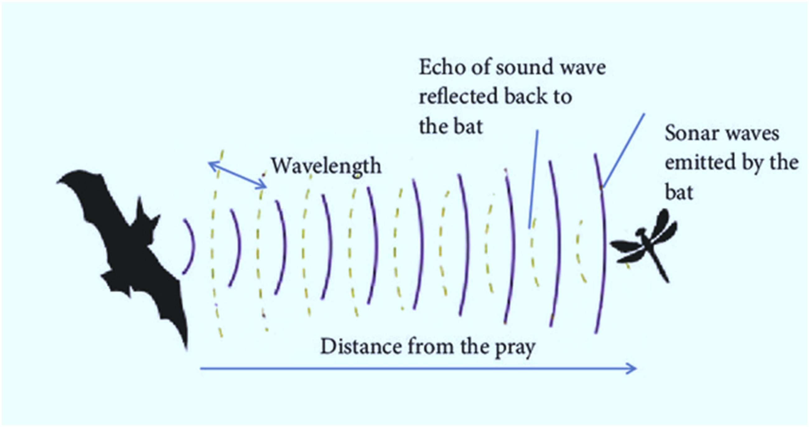
Bats are remarkable creatures that have drawn the attention of researchers across various disciplines due to their exceptional echolocation abilities. This sophisticated biological sonar, primarily used by microbats, enables them to navigate and detect objects by emitting short, high-frequency sound pulses and interpreting the returning echoes to determine distance and spatial positioning.
52
Bats can hunt even in full darkness because to this ingenious technique that allows them to discern between obstacles and prey.52,53 A population-based metaheuristic technique called the Bat approach (BOA), developed in 2010, is used to solve continuous optimization problems.
53
,
54
The BOA algorithm is influenced by natural occurrences like bat echolocation and bio-sonar. To aid in navigation or hunting, bats in the wild emit ultrasonic waves into their surroundings. They then receive the echoes of these waves and use the information to locate themselves, identify obstacles, and locate prey, as illustrated in Figures 1 and 2. Additionally, each agent in the swarm can identify optimal locations or move toward a previously discovered best position based on the collective experience of the swarm.
55
The Bat Algorithm has shown to be quite effective in providing answers to continuous optimization issues.
56
Bat behavior. Variation in bat echolocation activity across different environments.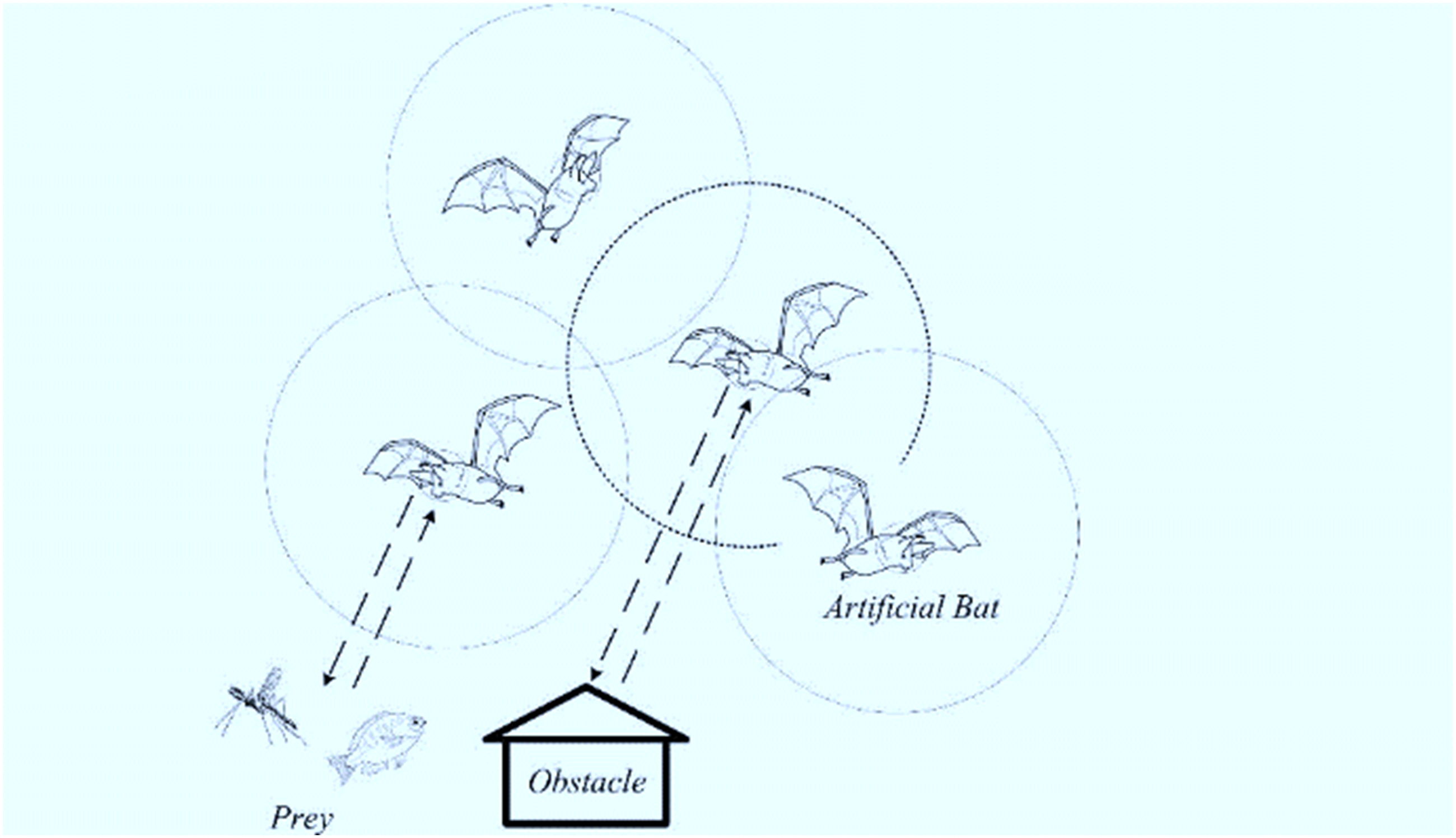
Mathematical representation of bat optimization method
Normal Bat Algorithm
As mentioned earlier, the BAT optimization algorithm is a metaheuristic algorithm inspired by the bat echolocation behavior. It is mainly used for global optimization problems. The algorithm starts by randomly generating an initial population of bats. Each bat represents a solution to the optimization problem. The bats in the population have their own positions and velocities at each iteration, the algorithm updates the position and velocity of each bat. The new position of a bat is determined by adding its velocity to its current position. The velocity of each bat is updated based on its previous velocity, the best solution it has found so far, and the global best solution. Additionally, each bat is characterized by an emission rate (loudness) and a pulse rate (frequency), which regulate the intensity and frequency of its emitted pulses. The loudness reflects the quality of a bat’s solution, while the frequency governs the balance between exploration and exploitation. Bats with higher loudness emit more frequent and intense pulses, allowing for a broader search. The algorithm also incorporates a local search mechanism, where a random solution is generated around the bat’s current position. If this new solution offers an improvement, the bat updates its position accordingly, enhancing convergence towards the optimal solution. 57
The algorithm also includes a random walk mechanism, where some bats undergo random movements to explore new areas of the search space. Here is the mathematical representation of the Bat Algorithm:
1. Initialization: - Set the population size N. - Initialize the position and velocity of each bat, X
i
and V
i
, randomly within the search space. - Initialize the frequency F
i
of each bat randomly.
2. Evaluate the fitness value for each bat: - Evaluate the fitness value f(X
i
) for each bat based on the objective function. 3. Update the velocity and position of each bat: - Update the velocity V
i
of each bat using the following equation - Update the position X
i
of each bat using the following equation


4. Apply the random walk and pulse emission mechanism: - Generate a random number A ∈ [0,1]. - If A > r, update the position X
i
of each bat using equation (2), where r is the pulse rate. - If A ≤ r, generate a new solution x_new randomly within the search space.
5. Apply the loudness and pulse rate updating: - Update the loudness A
i
and pulse rate r
i
of each bat using the following equations


6. Apply the frequency adjustment: - Update the frequency F
i
of each bat using the following equation

The algorithm continues until a stopping criterion is met, such as reaching a maximum number of iterations or achieving a desired fitness value.
7. Check the stopping criterion: - If the stopping criterion is satisfied, terminate the algorithm and return the best solution found so far. - Otherwise, go to step 2.
The following key considerations are taken into account when implementing the conventional Bat Algorithm: • A • • •
Figure 3 illustrates an example of how the Bat Optimization Algorithm (BOA) is used to fine-tune controller gains. The objective function (OF) formulation is based on the closed-loop system’s temporal response characteristics, including rising time (Tr), maximum overshoot (MP), and settling time (Ts), These parameters are affected by the nominal open-loop transfer function Go(S)’s natural frequency (Wn) and damping ratio (η). Block diagram of traditional BOA system with open loop.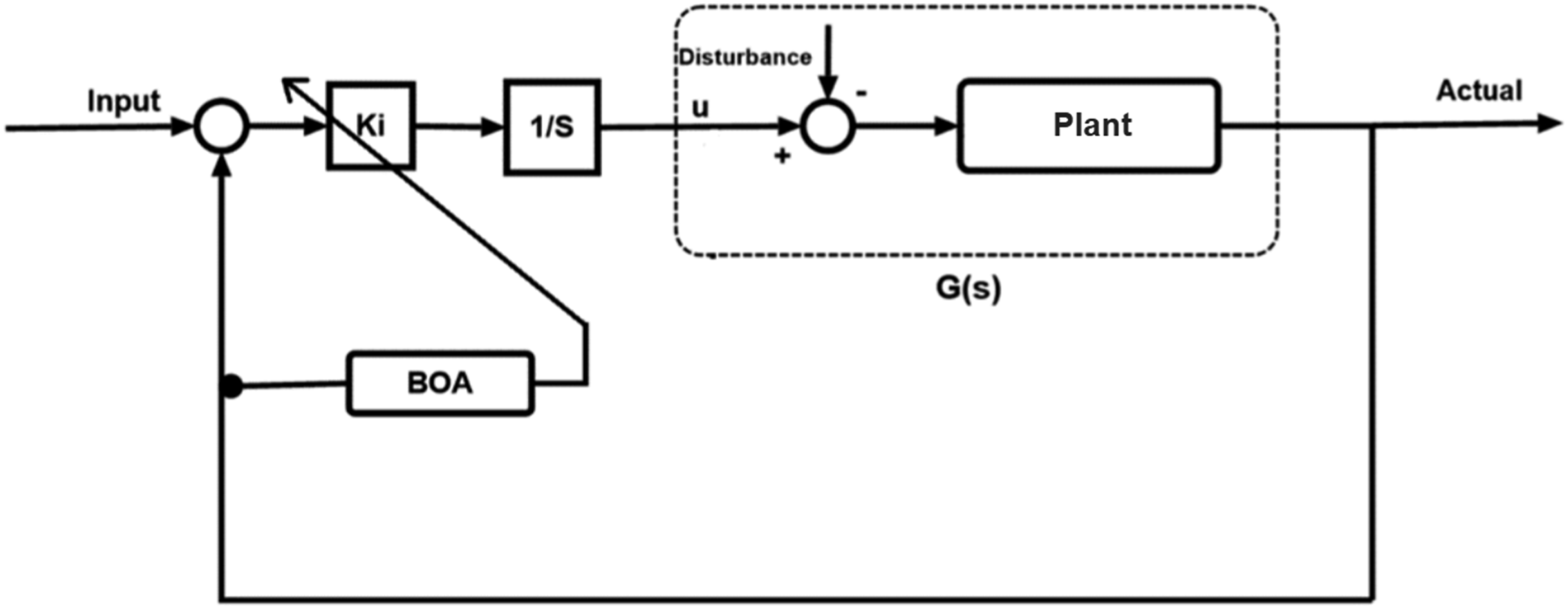
As shown in Figure 3, Go (S) is determined throughout each iteration based on two essential concepts: (1) maintaining a disturbance equal to zero. (2) and using nominal system elements. (3) This means that the standard Bat technique lacks the capacity to accept fluctuating disturbances or system parameter alterations in real-time when used directly in adaptive control. This restriction is a flaw in the traditional application of Bat in adaptive control issues.
BOA supported by BE
The BE has been incorporated to enhance the BOA, improving its ability to handle external disturbances and fluctuations in system parameters. The enhanced BOA aims to increase responsiveness to dynamic changes that may arise during any iteration, ensuring greater adaptability and stability in varying conditions. Figure 4 depicts the concept of BE, whereas Figure 5 depicts the open loop transfer function that the modified BOA algorithm uses at any given moment (i). The following is a definition of the modified BOA algorithm: (1) At each iteration, the plant input U
i
and plant output Y
i
are used to feed the BOA optimizer. (2) U
i
andY
i
may be used to determine the on-time transfer function G
i
(S) (3) The relation between G
i
(S) and Gi-1(S) (4) Relation between G
i
(S) and G
o
(S) can be expressed as Description of BOA with BE principle.
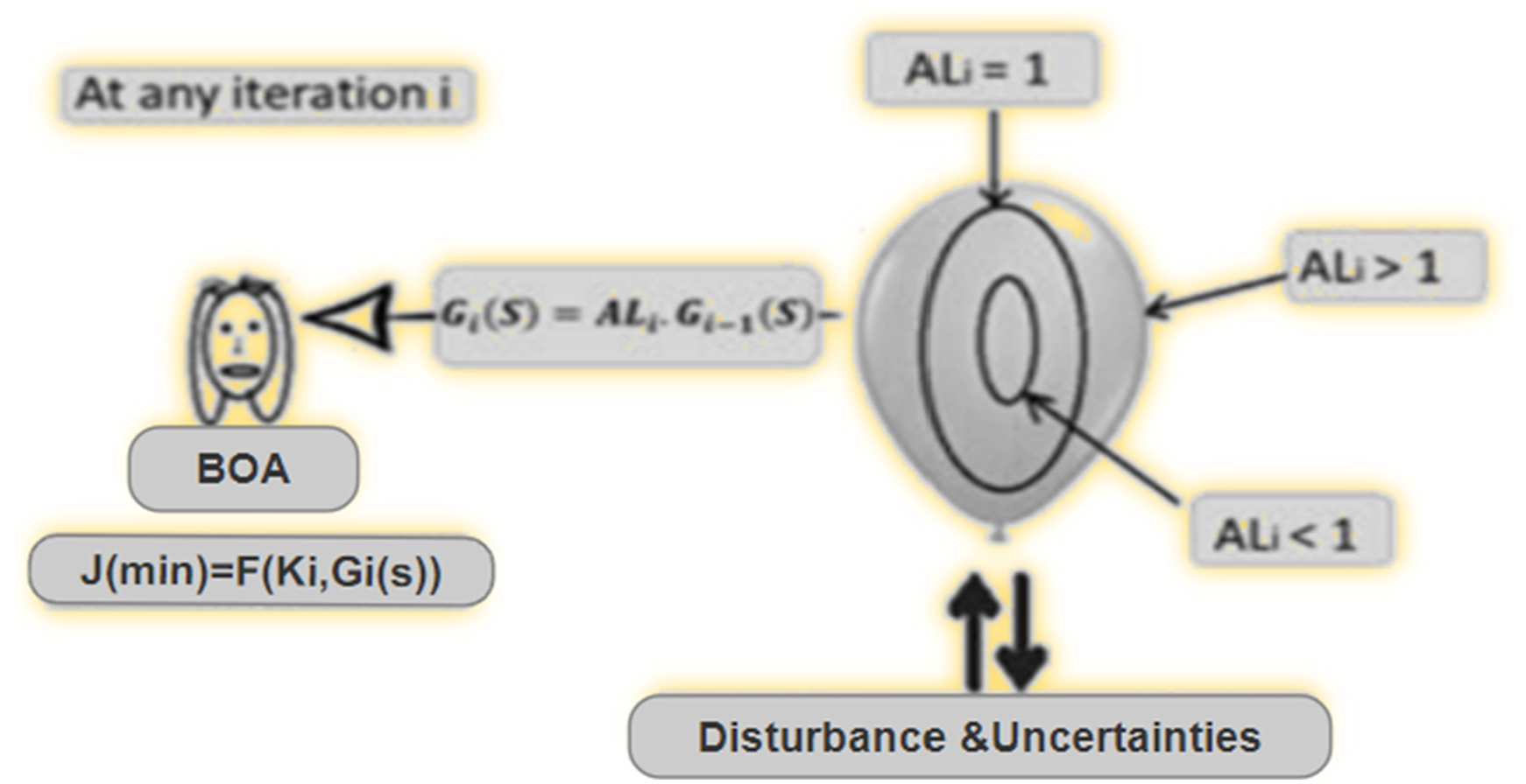


The impact of disturbances and system parameter variations during iteration i is represented by the parameter AL
i
. The shape of G
i
(S) dynamically adjusts based on the value of AL
i
, which is influenced by external disturbances and system uncertainties. This behavior can be metaphorically visualized as a balloon expanding or contracting in response to changes in air pressure, as shown in Figure 5. An open loop system representation for BOA with BE.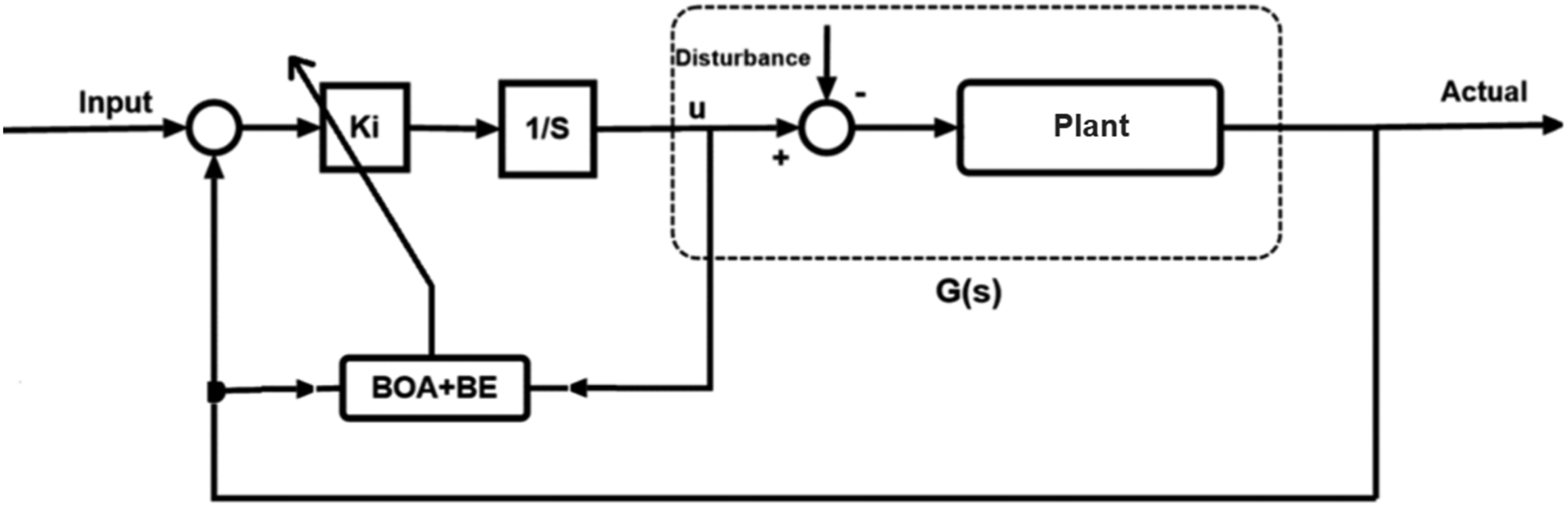
Figure 6 illustrates the flowchart of BOA, which is an adaptive control method that is suitable for industrial applications such as the control of power system, thermal control, and machines control. According to equation (8), G
i
(S) is dependent on both G
o
(S) and Flowchart of BOA algorithm.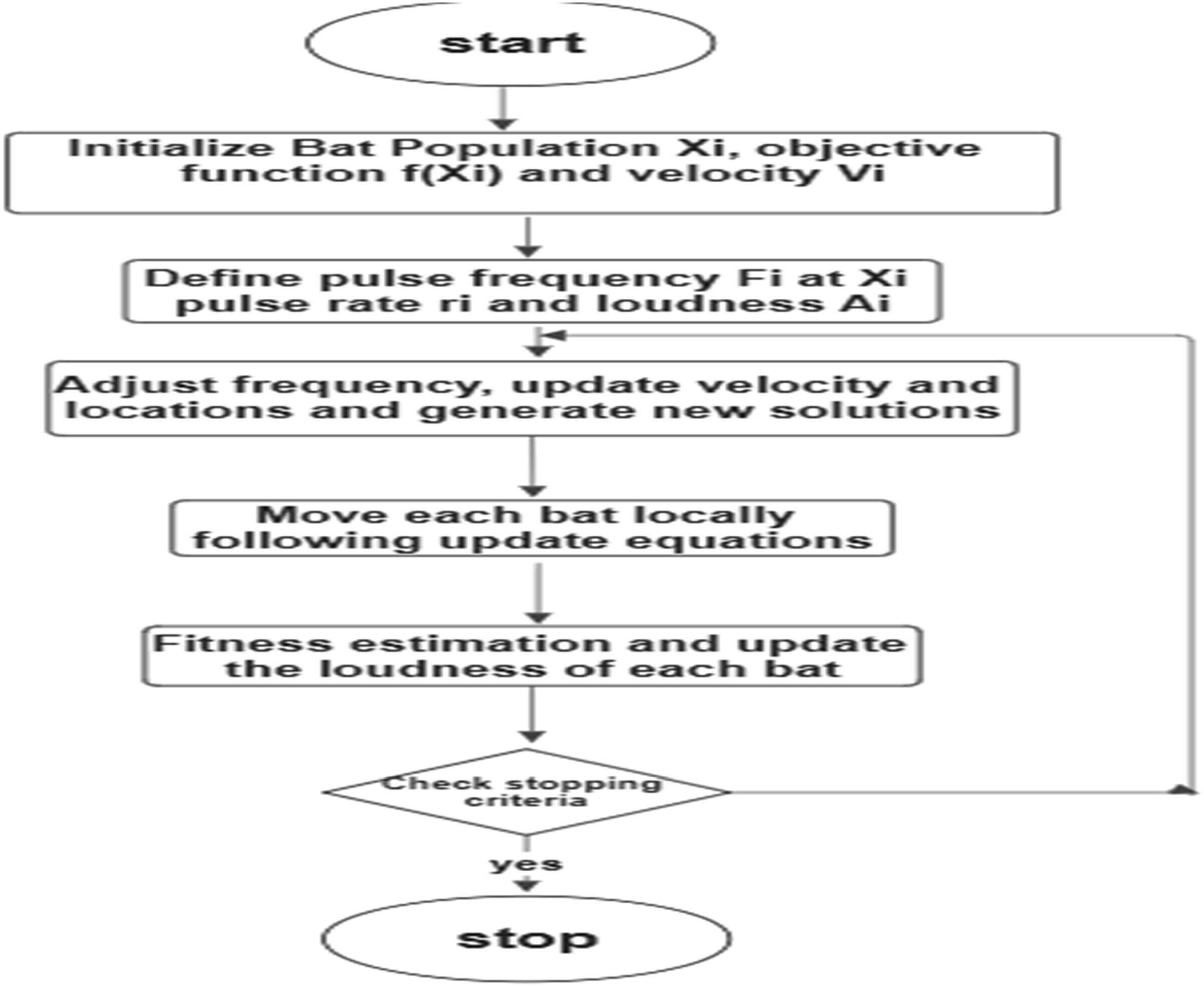
Studied systems
Armature controlled DC motor
This study focuses on a specific system, shown in Figure 7, consisting of a cart powered by a DC motor controlled by its armature. The cart, made of aluminum, moves along a shaft with a linear bearing. The motion is driven by a DC motor positioned on the track, which is linked to a pinion mechanism connected to a planetary gearbox.
58
Cart powered by DC motor study case.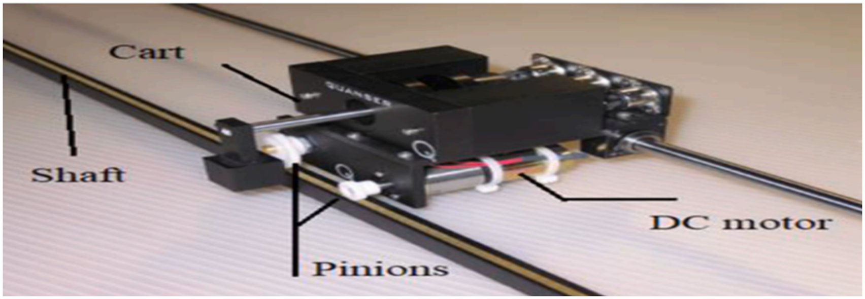
The car’s system’s behavior may be represented by an open loop transfer function, which is as follows


Using Newton’s second law, it can be determined that

The mechanical configuration of the car’s rack as well as pinion system can be calculated as

The motor’s driving force F
c
can be driven as

The DC motor’s torque can be stated as follows

Additionally, the angular velocity of the motor can be expressed as

Figure 8 shows a typical DC motor’s armature circuit. The application of Kirchhoff’s voltage law to this electrical circuit is represented as The DC motor’s armature circuit
1
.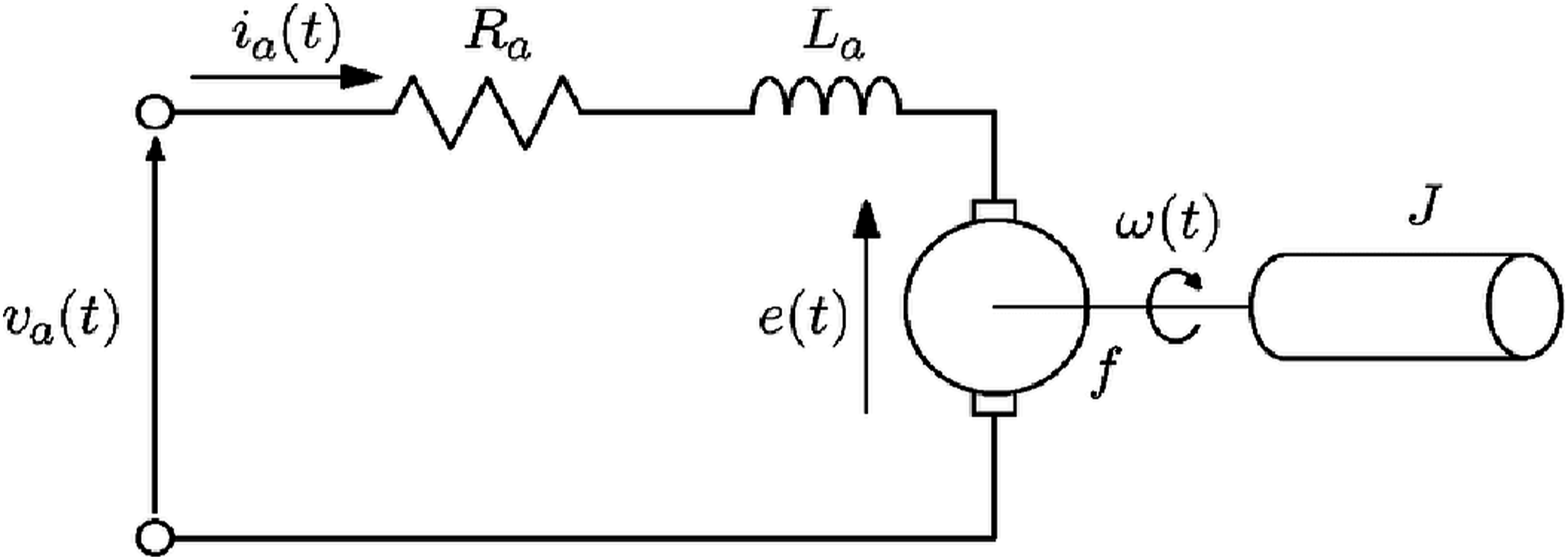

By neglecting the motor’s inductance, it can yield to


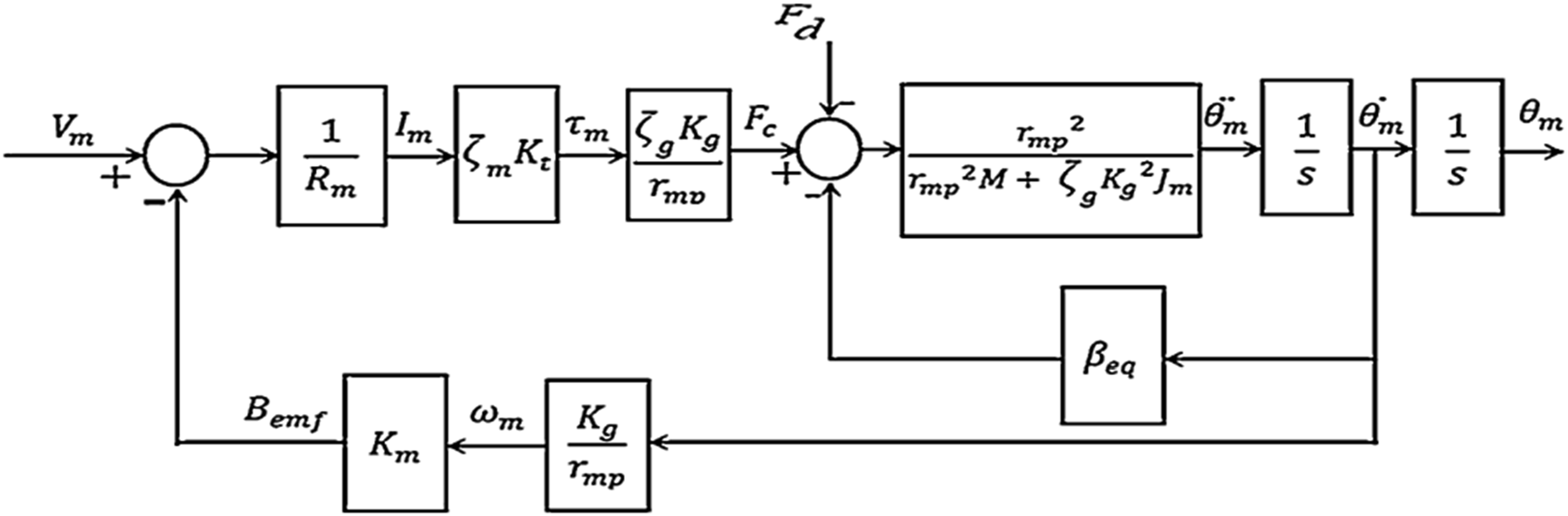
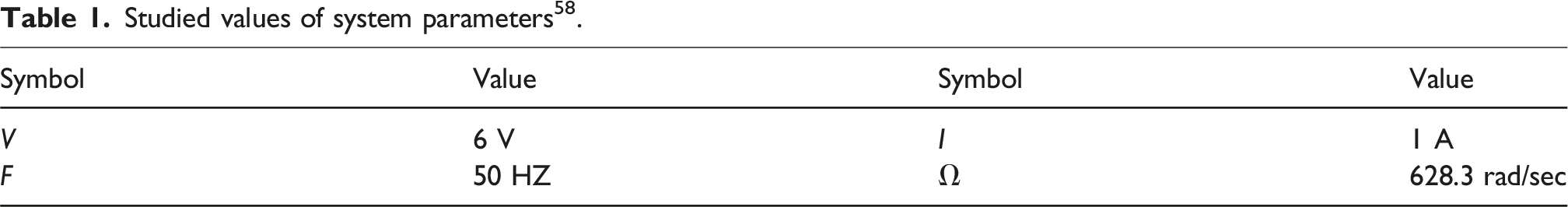
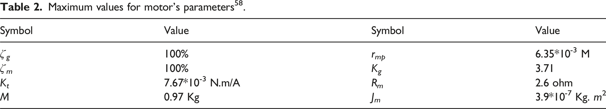
Figure 9 presents the block diagram, providing comprehensive information about the under-study armature-controlled DC motor. Detailed data regarding the system components can be found in Table 1. Additionally, Table 2 displays the maximum values associated with the electrical motor. Block diagram presents the DC motor design
47
. Studied values of system parameters
58
. Maximum values for motor’s parameters
58
.
Application of MICRO-GRID system
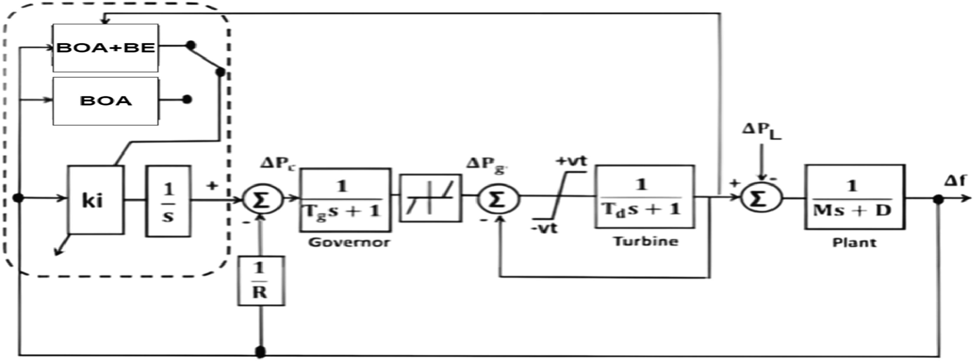
In the diagram presented in Figure 10, the setup of a micro-grid power system is illustrated. The equations
30
offer a detailed depiction of the dynamic model governing this particular micro-grid power system. Specifically, the connection between the total load-generator dynamics concerning the supply error (∆Pd -∆PL) and the frequency deviation (∆f) can be represented through mathematical expressions Block diagram of the model of microgrid power system.
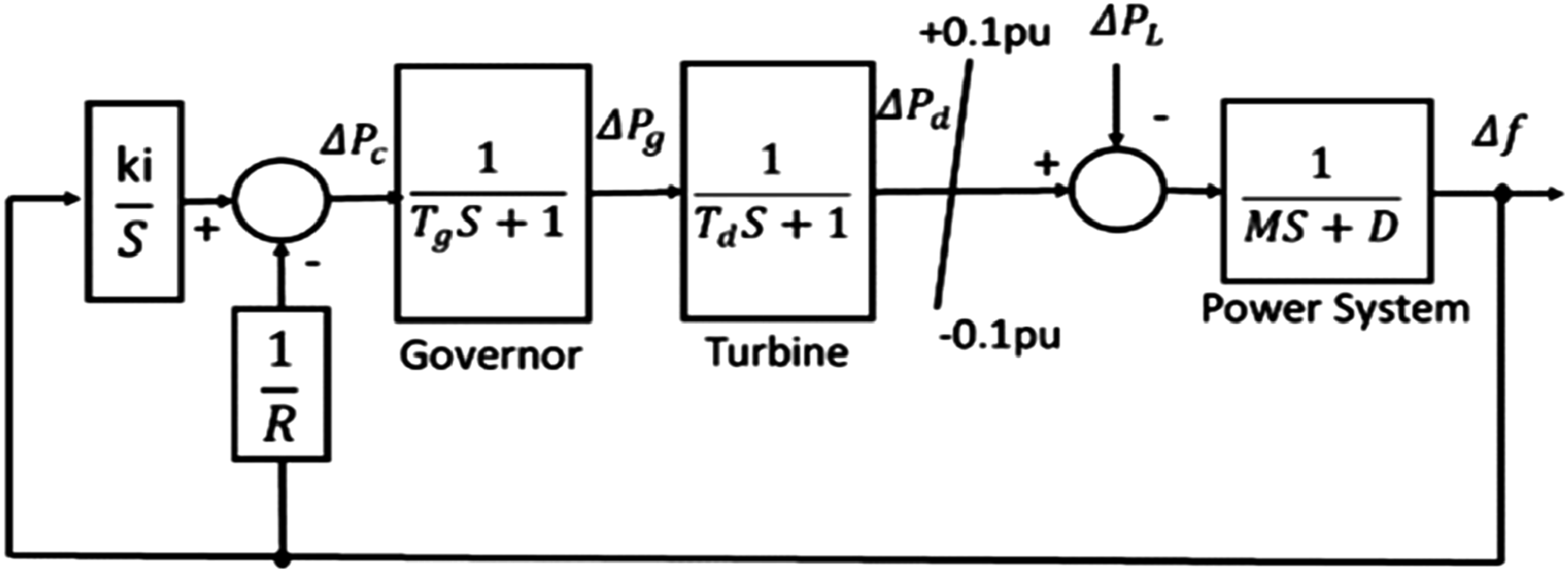
The diesel generator’ dynamic can be expressed as
The governor’ dynamic can be expressed as Block diagram of the model of the microgrid power system.
Adaptive position controlling for the studied systems
DC motor
Figure 12 depicts the PV controller’s architecture, while its model, G(S), is based on the armature-controlled DC motor showed before. The parameters Kp0 and Kv0 indicate the nominal values of K
p
and K
v
, respectively. These values are Kp0 = 274.61 v.sec/m and Kv0 = 5.531 v.sec/m, which were chosen to obtain system parameters of 0.15 sec rise time and 10% overshoot. The methods proposed attempt to optimize the PV controller’s gains K
p
and K
v
Straightforward design for the PV controller.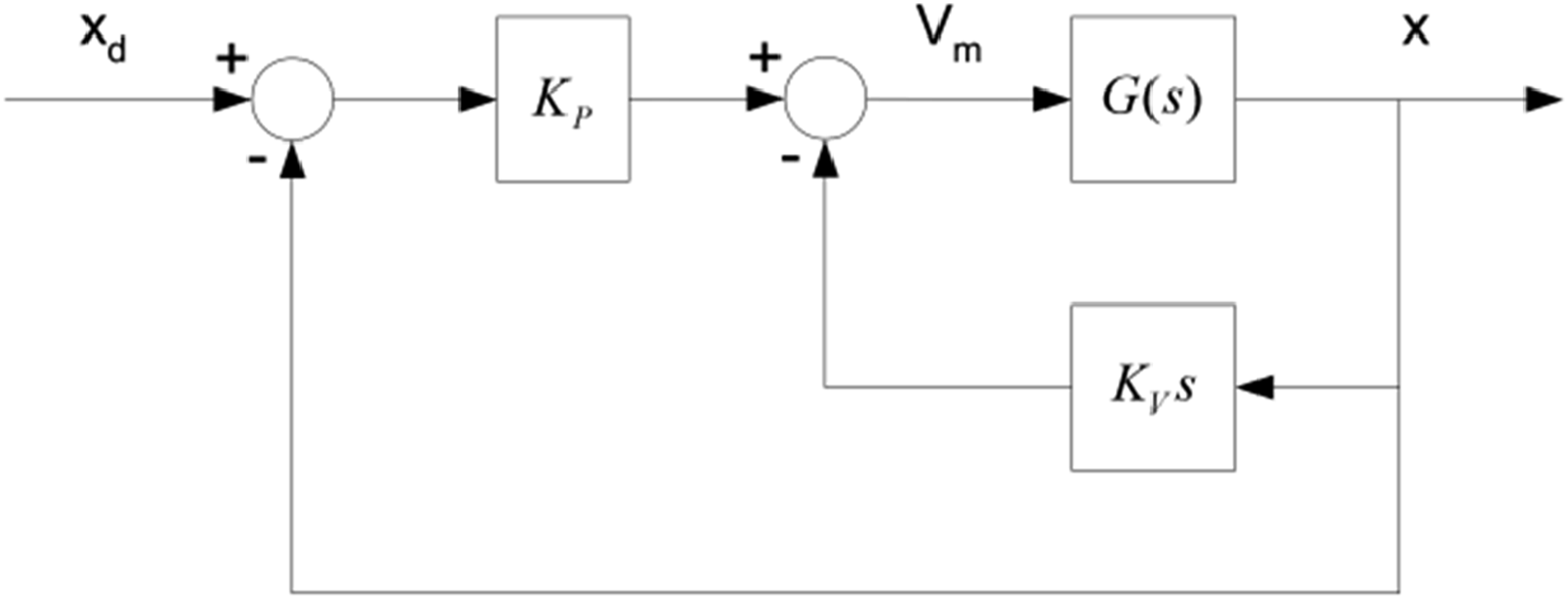
Using traditional BOA algorithm
Figure 11 demonstrates the application of a classical BOA optimization method in the system’s position controller. To optimize the BOA’s objective function (OF), the closed-loop transfer function of the system must first be calculated using equation (19), considering the nominal data provided in Table 1. Following this, additional steps can be performed
The feedback transfer function may be expressed as follows, as seen in Figure 10
Using BOA+BE algorithm
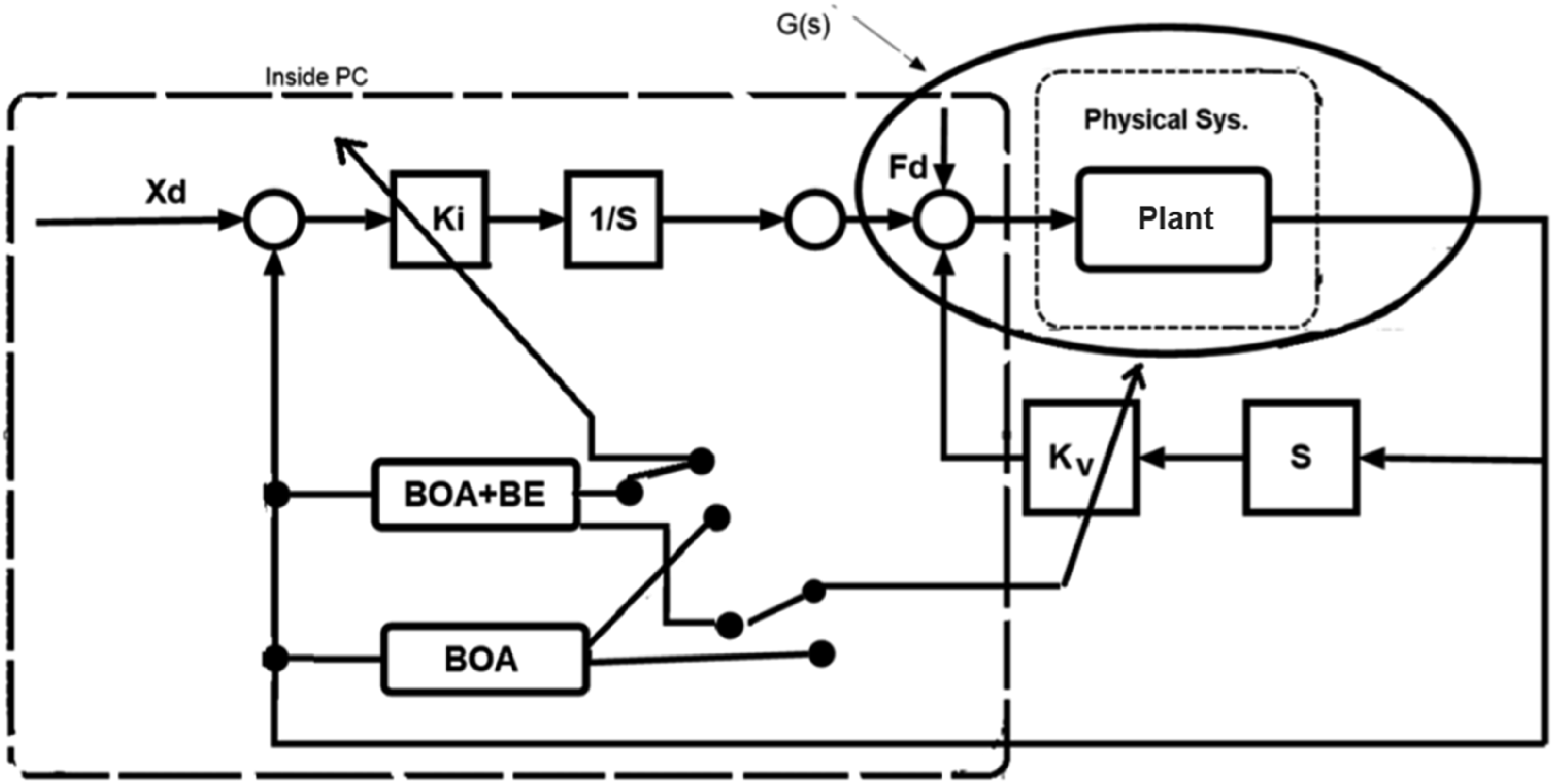
Figure 13 presents the position adaptive control system developed using the proposed BOA algorithm with BE. At each iteration, the system’s closed-loop transfer function can be computed by applying equations (8) and (19), while referencing the configuration in Figure 9. The computation procedure is as follows Block schematic of the controller-equipped system.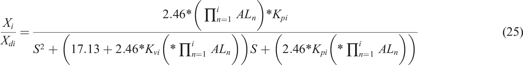
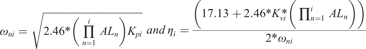
The values of ω
ni
and η
i
are utilized to compute the parameters M
pi
, T
ri
and T
si
for the second-order closed-loop system. It is evident that the minimum objective function, J
min
, in BOA+BE is affected by the values of K
pi
, K
vi
, as well as the term
The following illustration shows how the problem and algorithm interact: The computer executing the BOA + BE algorithm is given input U
i
and the plant’s output X
i
during each iteration. These signals are employed to calculate G
i
(S) using equation (2), while the previously stored value of Gi-1(s) is used to determine the value of AL
i
. This value, along with its accumulated historical values, is then utilized to calculate
LFC system
In Figure 14, we see a basic dynamic representation of a power system in a single region that influences the optimization process in BOA. This system can be likened to a closed-loop second-order mechanism Model representing the dynamics of a micro-grid within a specific controlled region.

The goal function this study aiming for is represented as follows
It’s important to highlight that any alterations to the system at any given point i do not impact the goal function. This implies that the BOA approach won’t effectively address such changes.
Results
Simulation results for DC motor application
The control parameters for the proposed BOA+BE and the conventional BOA were carefully selected to ensure a fair comparison. The initial tuning of BOA was performed using empirical methods based on system dynamics, while BE was introduced to allow real-time adaptability to system variations. The objective function was designed to minimize settling time, overshoot, and steady-state error, ensuring optimal performance across different test cases. The selection of control parameters for both the conventional BOA and the proposed BOA+BE was based on a thorough analysis of system dynamics and performance requirements to ensure optimized response and stability in DC motor position control chosen through time-domain response analysis to provide a balance between response speed and steady-state accuracy. In contrast, BOA+BE dynamically adjusted
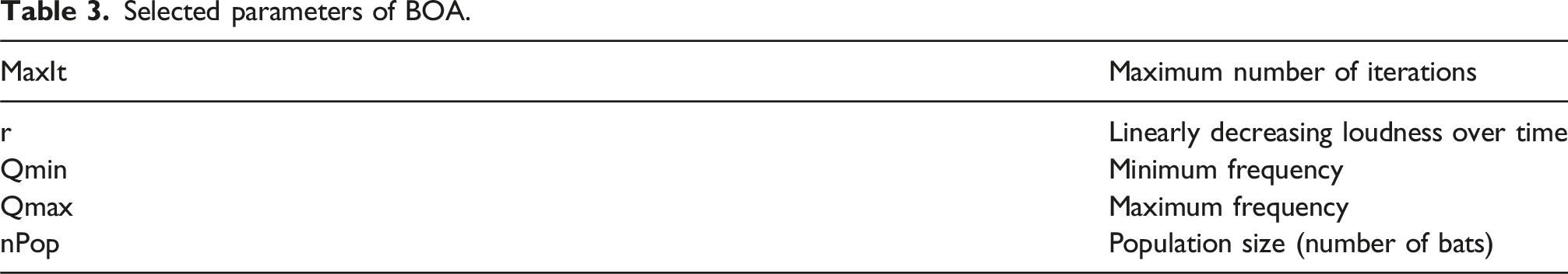
The following parameters are included in the modified BOA technique: - Initial values for Kp0 = [270, 272, 274, 275, 286] - Initial values for Kv0 = [5, 5.75, 5.8, 5.85, 5.96]. - AL1 = 1
Selected parameters of BOA.
The proposed control algorithm for the DC motor system was implemented using the Simulink package in MATLAB, which served as the simulation environment.
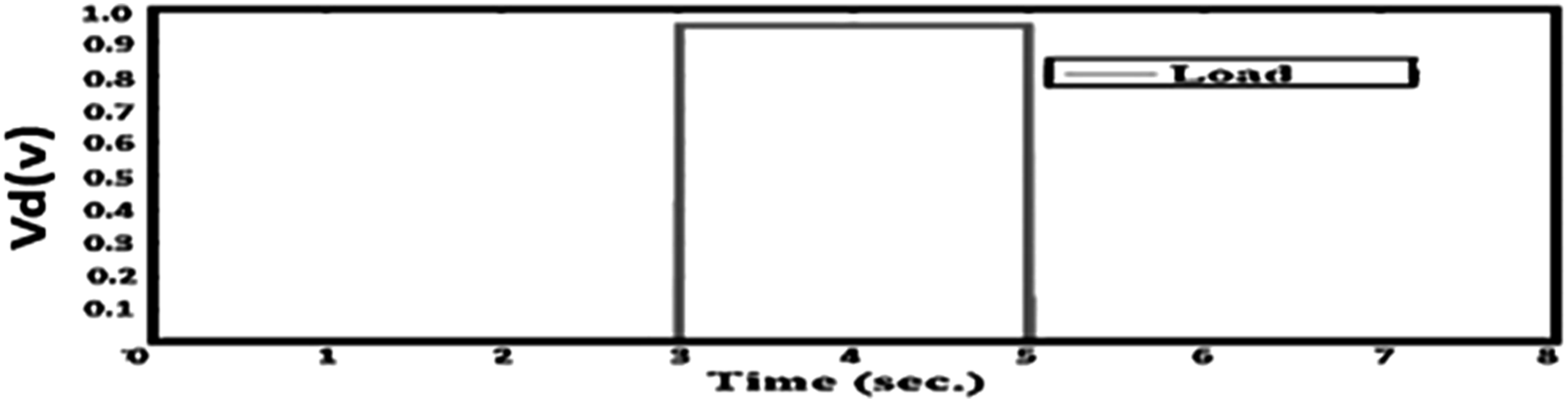
In this study, to enable measurability, physical disturbances were replaced by an equivalent voltage via the sum point movement option, as shown in Figure 15. The system under analysis was tested under many scenarios like: a sudden change in the desired input and a sudden load disturbance. The associated load disturbance, represented in Figure 16, was included to evaluate its influence on the proposed system. It began at t = 3 s and concluded at t = 5 s with a value of 0.95 volts. The required motor position signal began at 1.5 s with an initial displacement of 15 mm and ended at 6 s. The option of sum point movement. Load disturbance.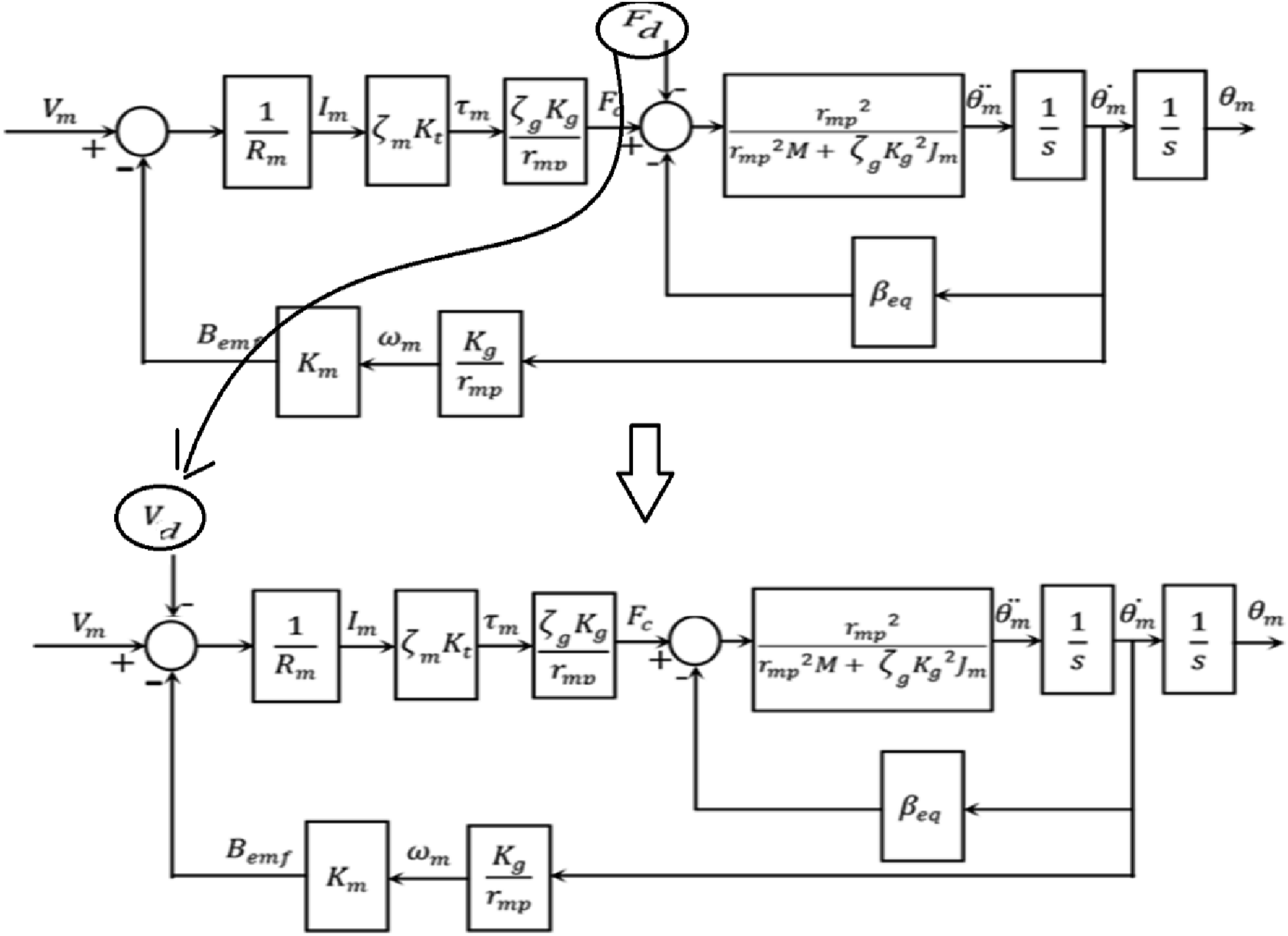
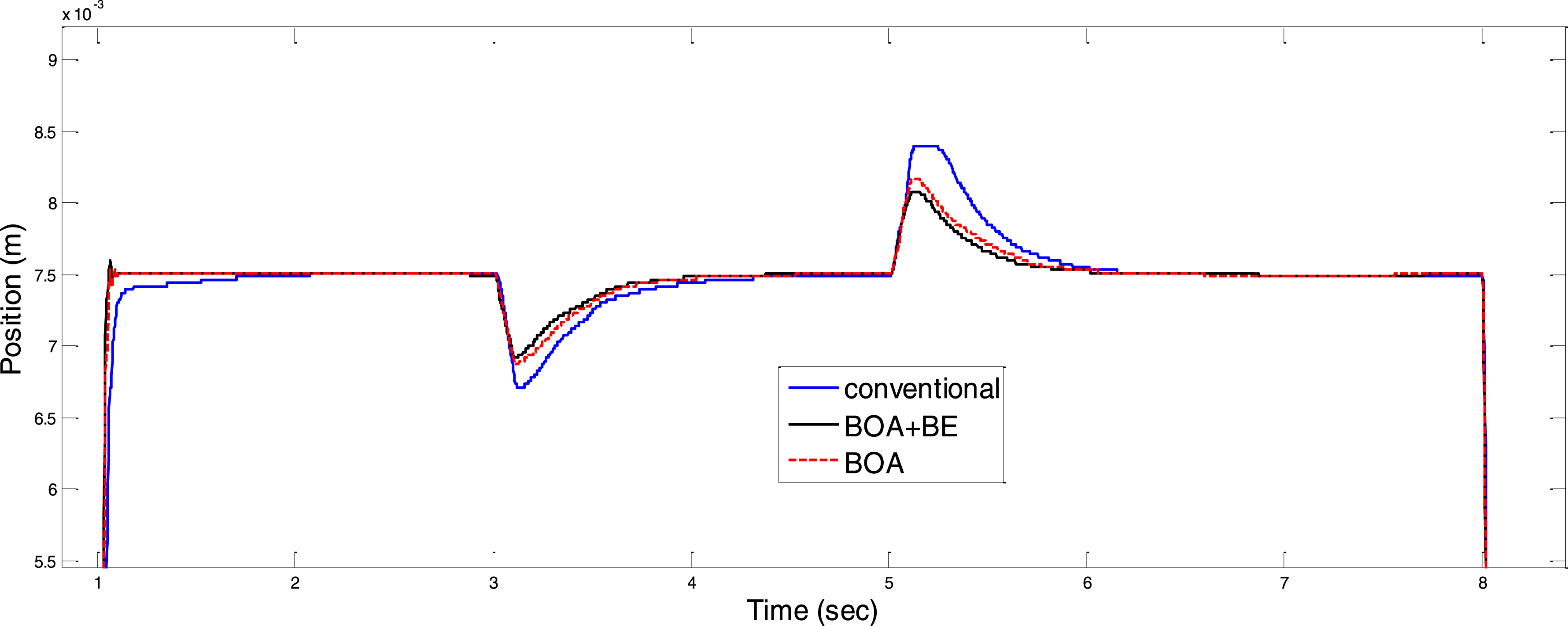
A comparison was made between the system with the classical BOA algorithm-tuned controller and the system with the conventional PV controller. The results, illustrated in Figure 17, indicate that using the PV controller tuned by the normal BOA algorithm reduced the overshoot by approximately 35% in comparison to the fixed parameters PV controller. Additionally, a comparison was made between systems employing the classical BOA algorithm and the modified BOA algorithm with BE During a load disruption and a step reference variation. The corresponding results are illustrated in Figure 18. The result of tuning the PV controller using the conventional BOA in the case of a load disturbance. Results of tunning PV controller by conventional BOA/BOA+BE in the event of a load disturbance.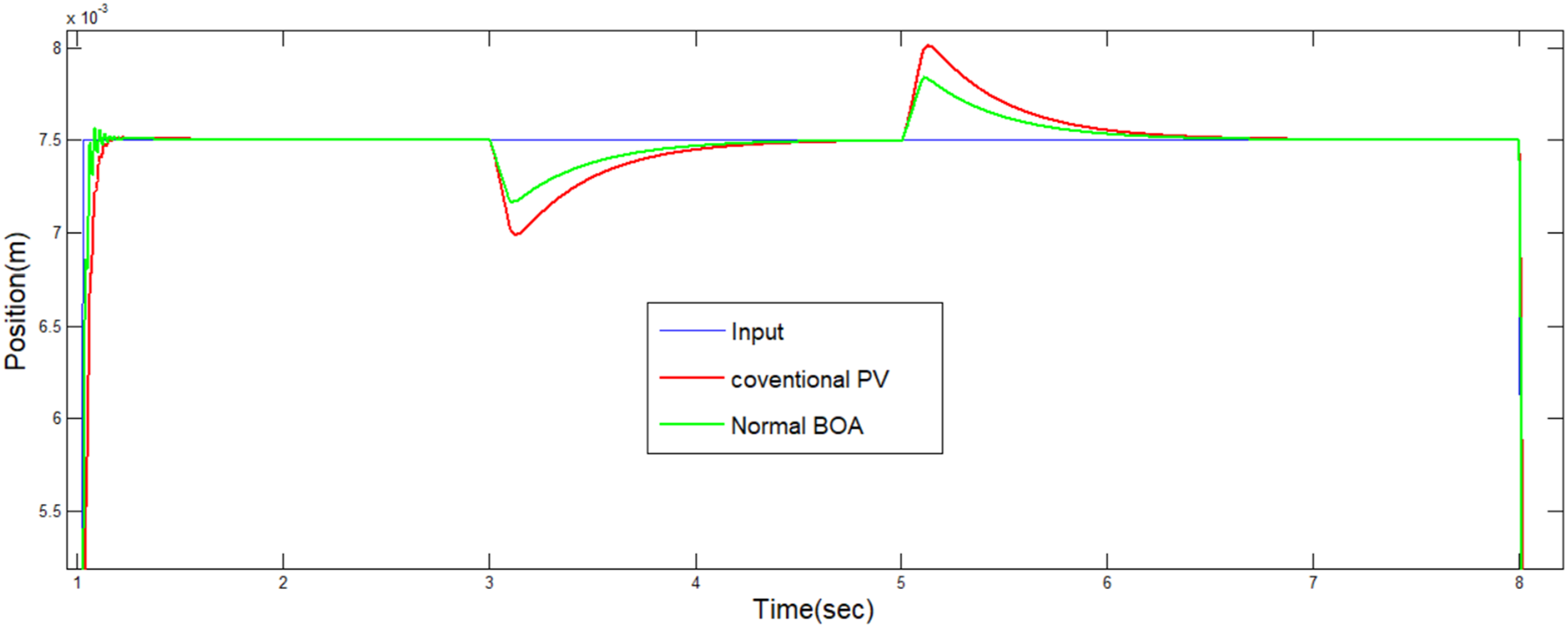
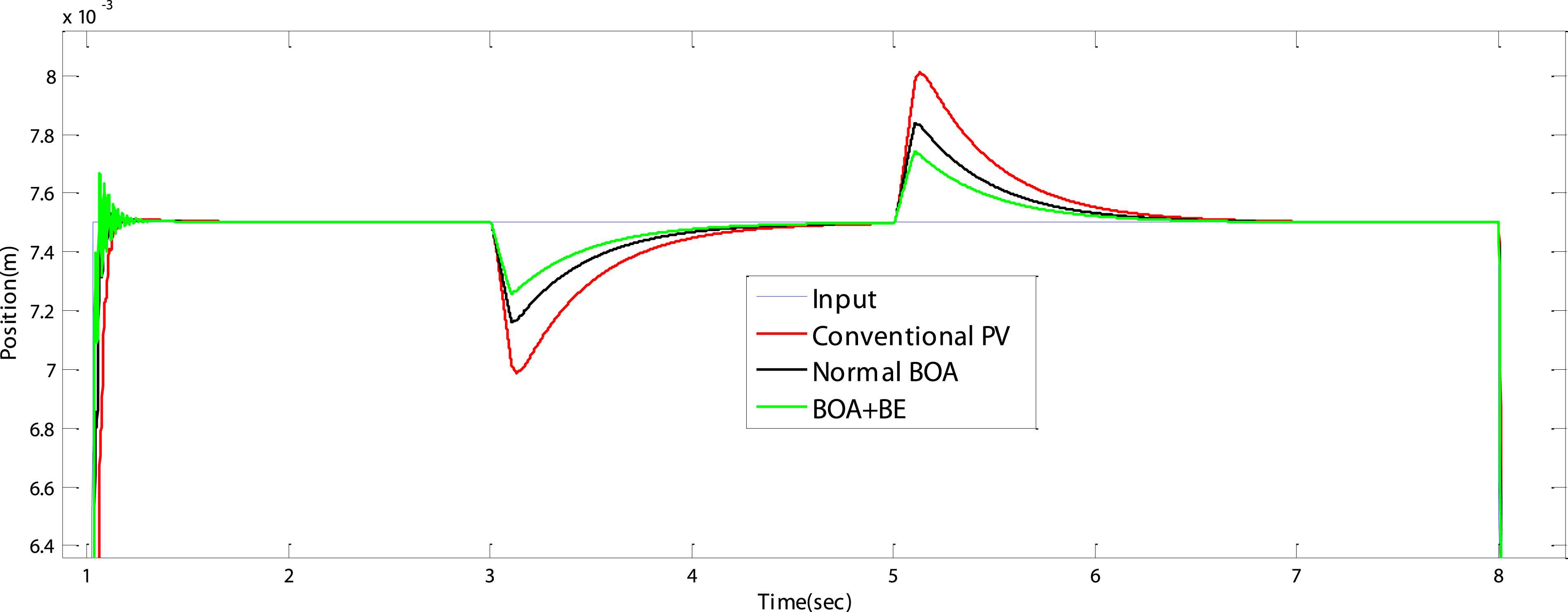
Time response parameters.
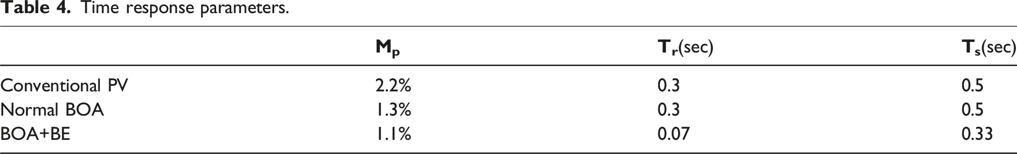
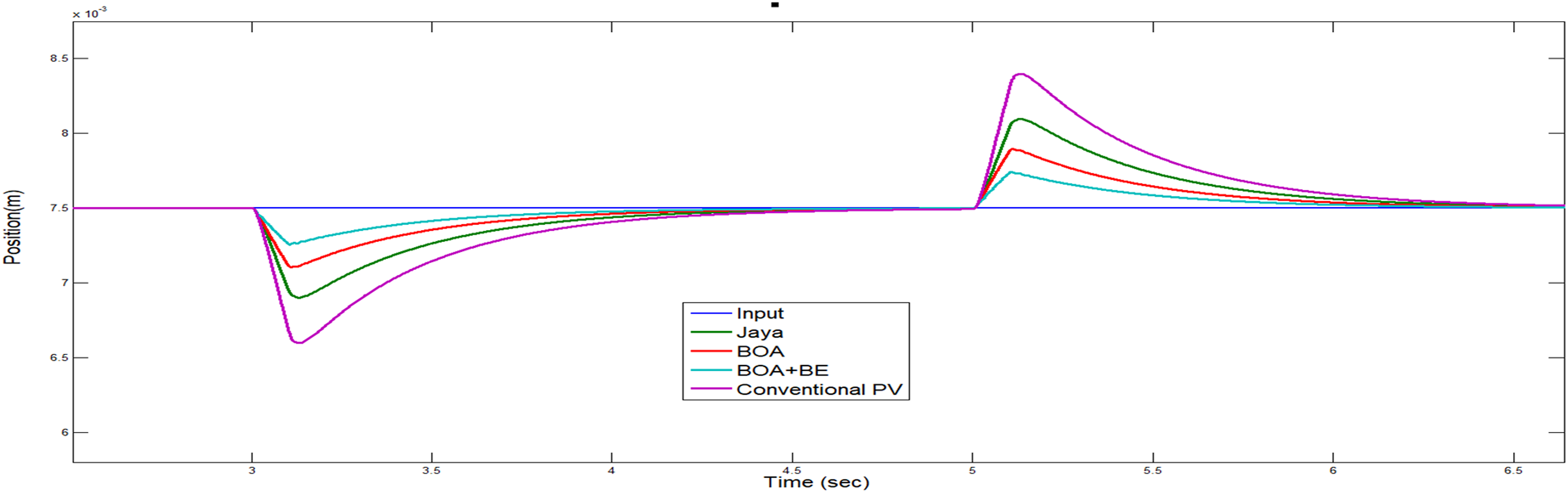
Table 4 highlights that the proposed BOA algorithm with BE yielded the best overshoot, rise time, and settling time compared to the conventional PV controller. However, when comparing the system with the classical BOA algorithm, it was found to have a better overshoot but similar settling time and rise time. Figures 17 and 18 show how the proposed adaptive PV controller, adjusted by either the standard BOA algorithm or the modified BOA algorithm with BE, successfully solved the load disturbance issue. Furthermore, in Figures 19 and 20 a comparison has been made with Jaya algorithm, illustrate that the performance of the modified BOA technique outperformed the other approaches. Focus on the consequence of tunning PV controller using conventional BOA/BOA+BE compared with Jaya in the event of a load disturbance. Focus on Tunning PV controller using conventional BOA/BOA+BE compared with Jaya in the event of a load disturbance.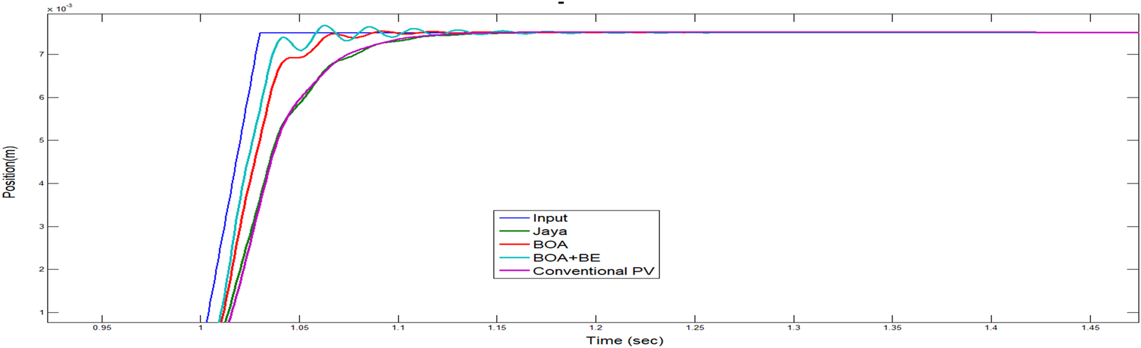
Case 2: Overloading scenario
The system was tested with a load 1.5 times greater than the nominal load. The results showed that BOA+BE outperformed both the traditional BOA and fixed-parameter controllers. It significantly reduced the overshoot (initial peak in the system’s response) and achieved a faster settling time (the time taken to stabilize after a disturbance). This improvement is due to the Balloon Effect, which dynamically adjusts the objective function in real-time, allowing the system to adapt to increased load and disturbances, thereby enhancing its stability and efficiency as shown in Figure 21. System response under overloading conditions.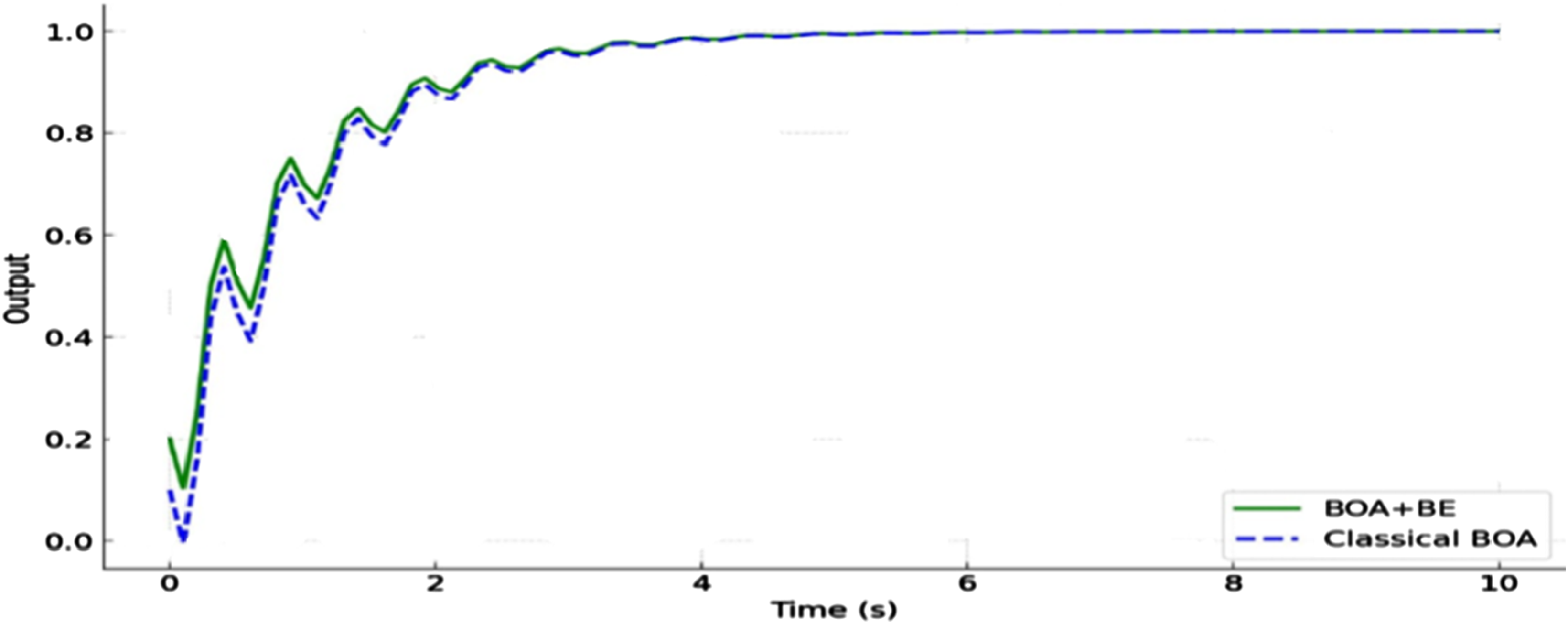
Case 3: Response to high-frequency disturbance
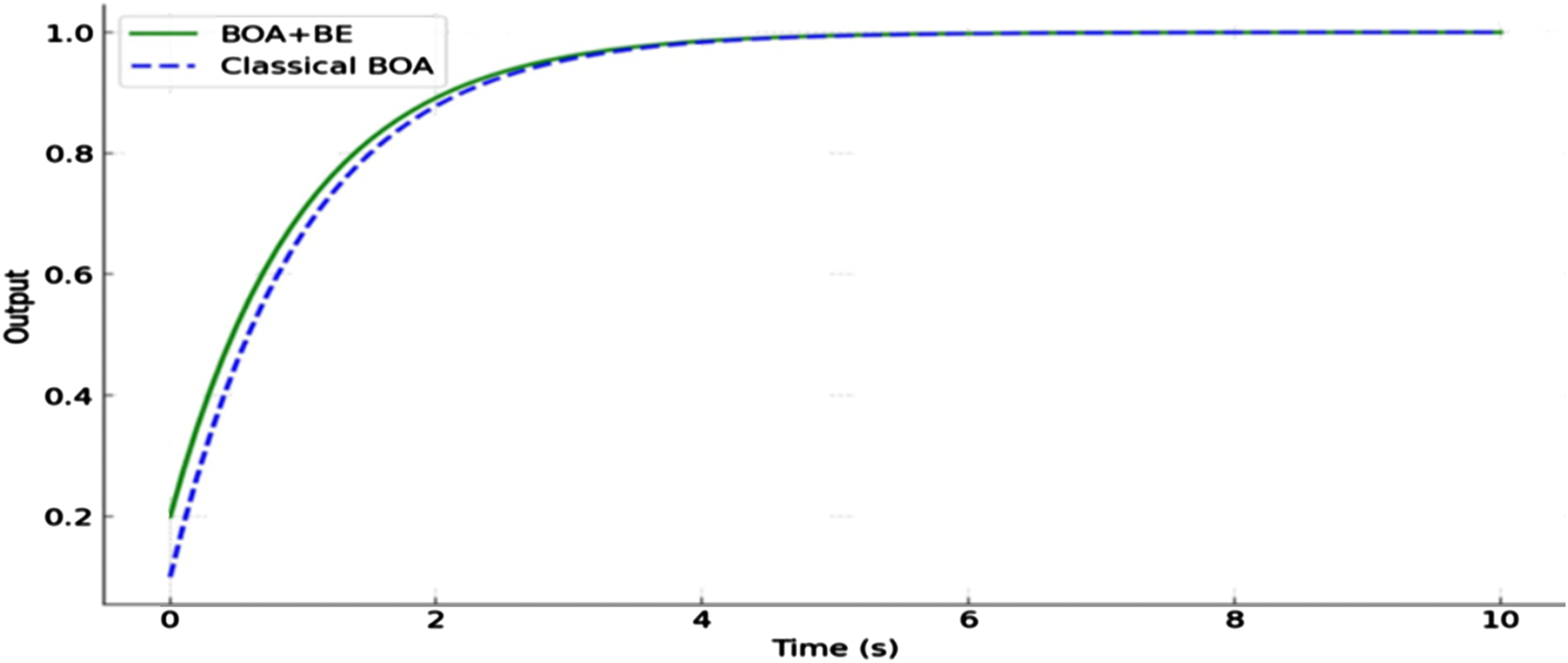
In Figure 22, the system was tested under high-frequency disturbances. The results showed that BOA+BE outperformed Classical BOA in stabilizing the system. BOA+BE responded faster than Classical BOA, meaning the system adapted more quickly to the changes caused by the high-frequency disturbances. It also reduced oscillations, providing a smoother and more stable response. The Balloon Effect played a crucial role in enhancing the system’s robustness, allowing it to handle high-frequency disturbances more effectively and stabilize more efficiently, demonstrating its superior performance in such conditions. Response to high-frequency disturbance.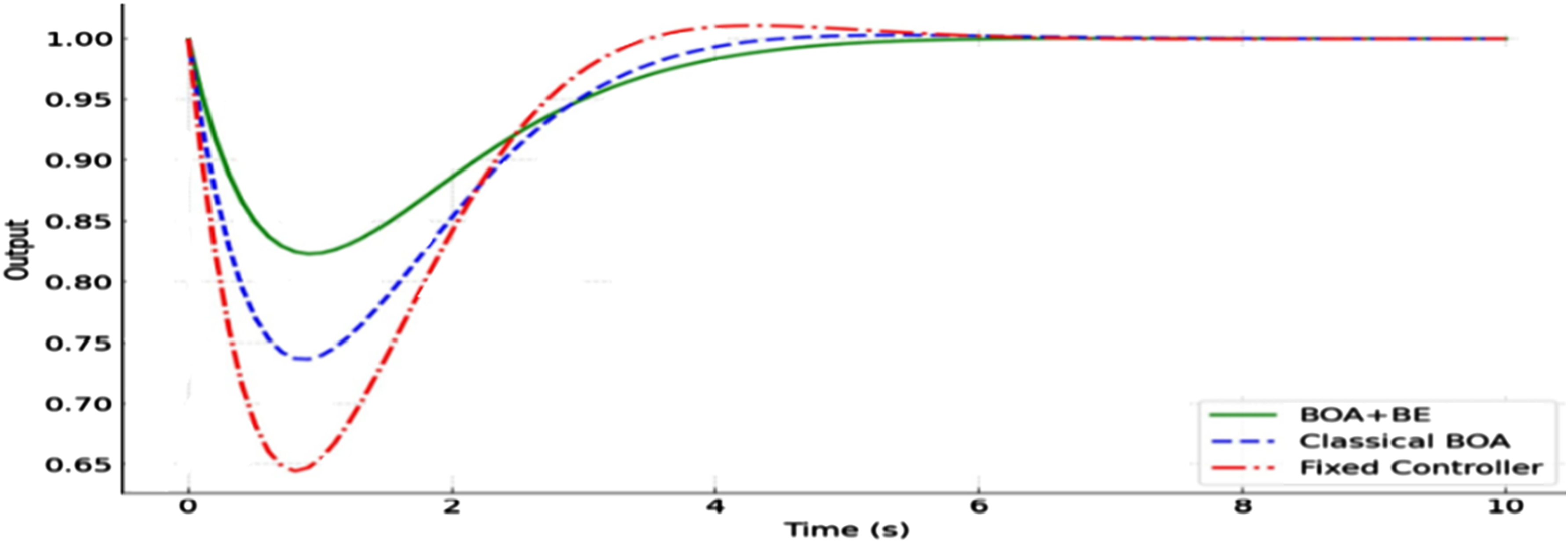
Experimental results for DC motor application
Case 1
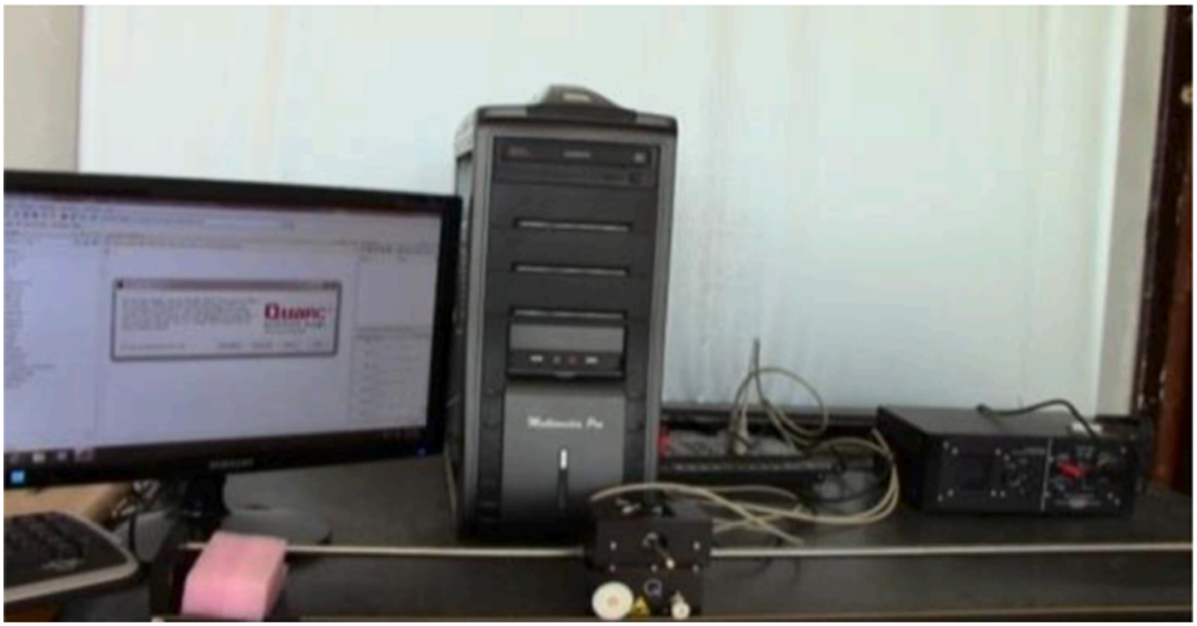
Figure 23 below displays an experimental version of the suggested car that is powered by a DC motor. The communication between MATLAB, which is executed on a PC, and the DC motor is facilitated by the QPIDe data acquisition card and QuanserVoltPAQ, a voltage amplifier unit. To measure the position, a single-ended optical shaft encoder is utilized as a sensor.
58
The arrangement of the hardware can be seen in Figure 24. The same test cases used in the simulation were repeated in the experimental setup. The simulations and optimizations were performed on a personal computer with the following specifications: Intel Core i7-12700H processor, 16 GB RAM, and an NVIDIA RTX 3060 GPU, running Windows 11. The implementation and testing were conducted using MATLAB R2023a and Simulink, which were used for system modeling, controller tuning, and performance evaluation. These specifications ensured efficient computation and accurate real-time simulations. The proposed system using digital MATLAB controller. Experimental setup.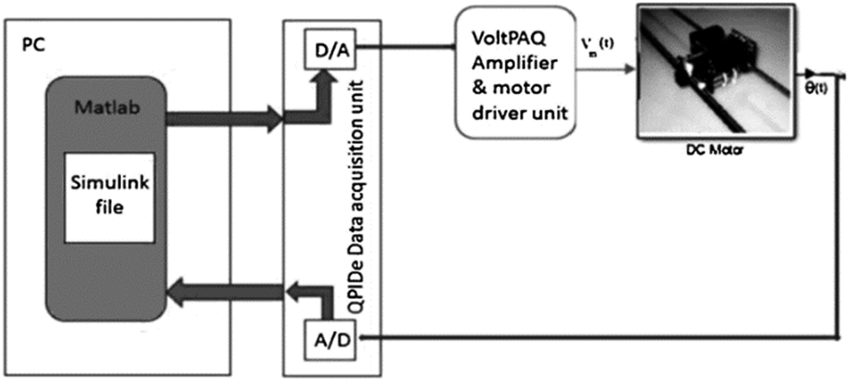
The experimental results are presented in Figure 25, Figure 26, showcases the system responses for both the classical and tuned PV controllers. It is evident that the suggested adaptive technique had a positive impact on the system’s response to step load changes and step inputs. When using the normal BOA algorithm, the overshoot was reduced by approximately 30% compared to the conventional PV controller. The results of tunning PV controller using conventional BOA during a load disturbance. The outcome of tunning PV controller using conventional BOA/BOA+BE in the event of a load disturbance.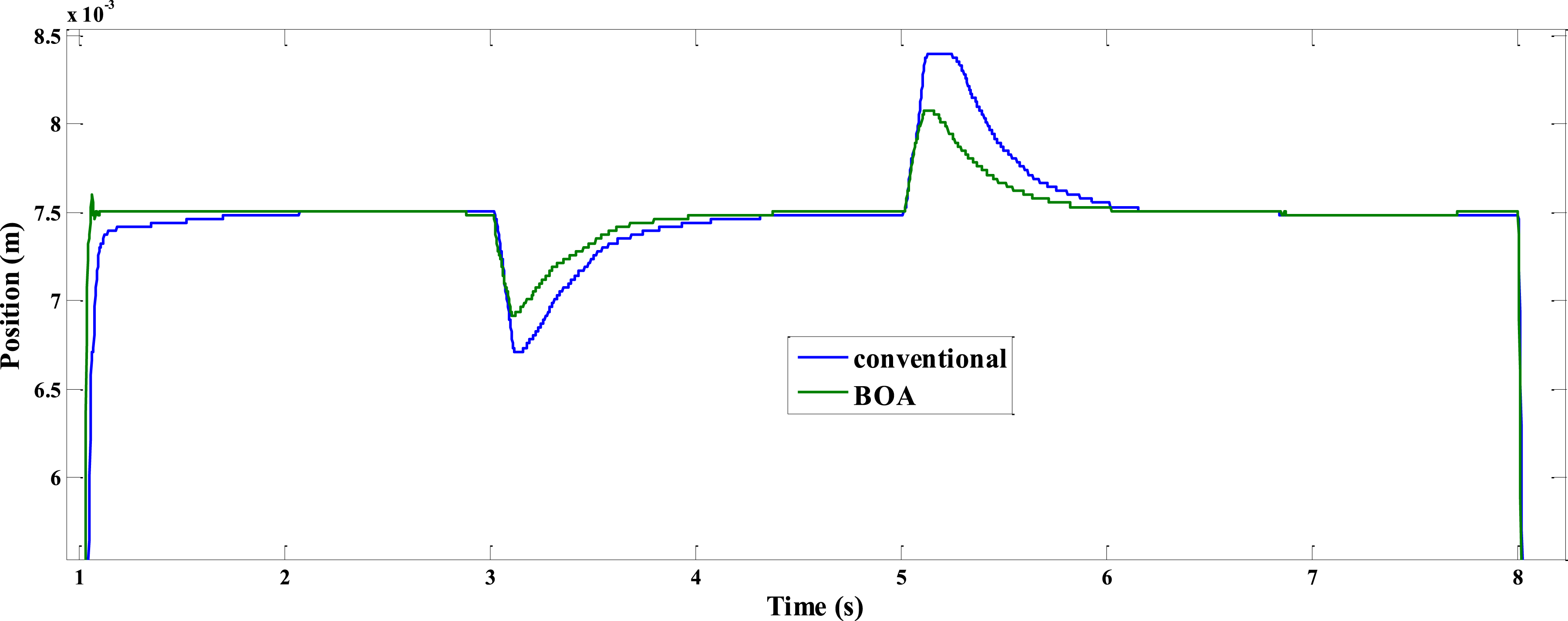
Furthermore, Figure 26 highlights the superiority of the system with the modified BOA algorithm with BE over the system with the normal BOA algorithm when subjected to load disturbance. It is clear that the system response while applying the modified BOA algorithm with BE is steady and smooth, while the system response using the standard BOA algorithm exhibits poor performance during the initial three seconds, accompanied by high ripples.
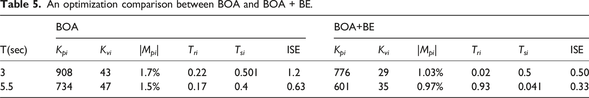
An optimization comparison between BOA and BOA + BE.
Case 2: Load disturbance with increased Amplitude
Figure 27 shows in this case, the system was tested with a load disturbance of 1.2 V, which was higher than the nominal 0.95 V. The results showed that the BOA+BE approach significantly outperformed the traditional BOA. Specifically: • There was a 25% reduction in overshoot. • The settling time improved by 15%. Experimental response under higher load disturbance.
These improvements in overshoot and settling time highlight the robustness of the BOA+BE method in handling more intense disturbances compared to traditional methods, ensuring that the system could stabilize more quickly and efficiently.
Case 3: Dynamic inputs
In this scenario, the motor was subjected to dynamic input signals, which simulate real-world operational changes. The system’s response was tested for its ability to adapt to such changes The BOA+BE system showed seamless adaptation, maintaining smooth operation without significant oscillations The Balloon Effect helped the system fine-tune its parameters in response to changing inputs, ensuring stable performance despite the variability.
This case demonstrates the effectiveness of the BOA +BE in dynamic environments where input signals fluctuate, making it a reliable control method for real-time applications as presented in Figure 28. Experimental response to dynamic input.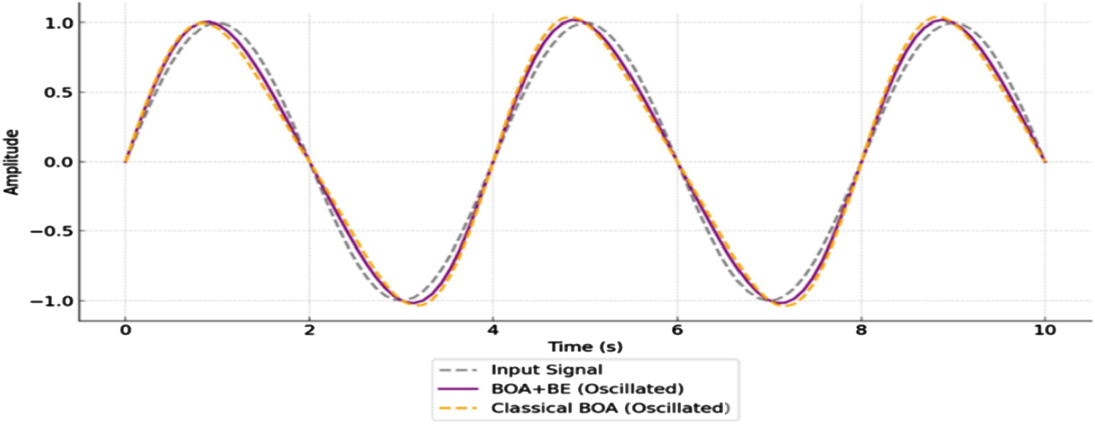
Case 4: Energy consumption test
In Figure 29, the energy consumption was measured during prolonged operation with both fixed and dynamic inputs BOA +BE reduced energy consumption by 20% compared to the classical BOA. Experimental energy consumption comparison.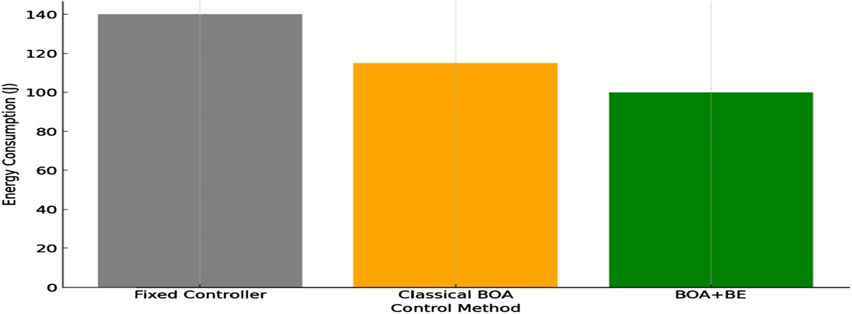
Case 5: Robustness to noise
Here, the system was subjected to electrical noise to simulate real-world interference. The results showed that the BOA+BE approach was highly robust. It minimized oscillations compared to the traditional BOA. The system maintained stable performance despite the noise, demonstrating the Balloon Effect’s ability to adapt the optimization process in real-time to handle such external disturbances.
This case emphasizes the BOA + BE’s capability to enhance system resilience in noisy environments, ensuring consistent performance even when external interferences are present as shown in Figure 30. Experimental response under noisy conditions.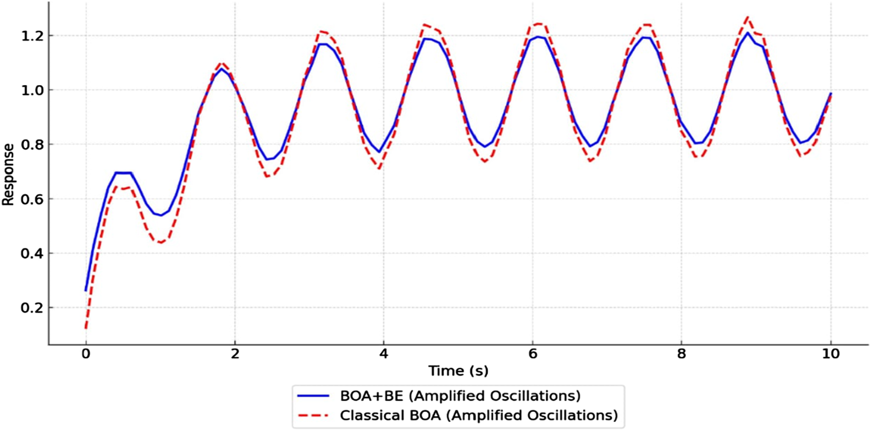
Simulation results of microgrid LFC
For the microgrid frequency regulation, the controller parameters were initially set at Kp = 1.2, Ki = 0.5, and Kd = 0.02, and BOA+BE adapted them in real-time to Kp = 1.8, Ki = 0.7, and Kd = 0.03, leading to improved disturbance rejection.
To ensure fairness in comparison, all optimization algorithms were executed under identical conditions, using the same initial population size (N = 30), maximum iterations (100), and convergence criteria (10-5 tolerance). The control gains were tuned based on performance metrics, and each algorithm was tested 10 times to ensure consistency. This methodological approach guarantees that the observed improvements in BOA+BE are due to its enhanced adaptability rather than differences in experimental conditions.
Case 1
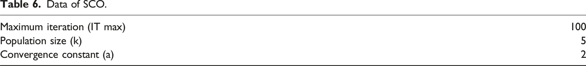
Data of SCO.
Frequency deviation.
Case 2 frequency deviation under varying load
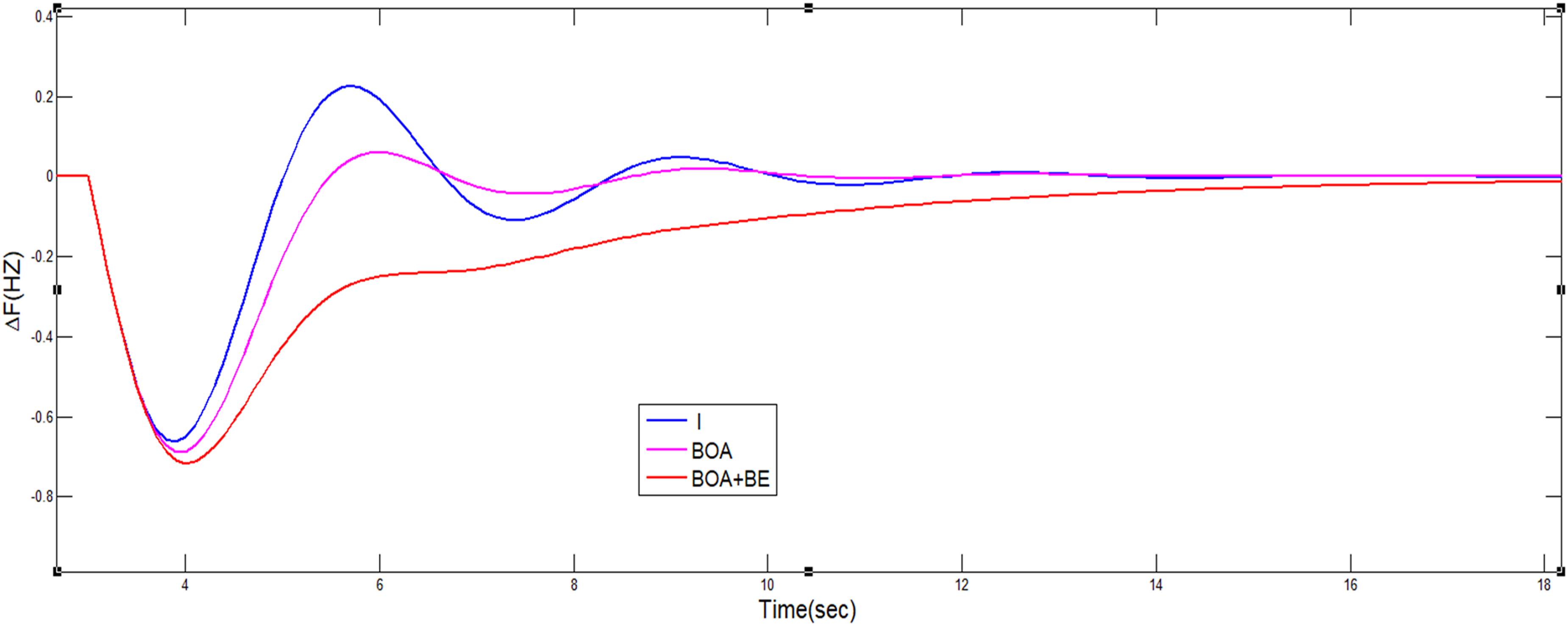
Results in this case is illustrated in Figure 32 the system was tested for its response to varying loads, focusing on frequency deviations. The results showed that the BOA+BE method performed significantly better than traditional BOA in maintaining lower frequency deviations under load changes. This improvement indicates that the Balloon Effect helps the system adapt to fluctuating loads more effectively, providing greater stability and faster response to changes in power demand. Frequency deviation under varying load.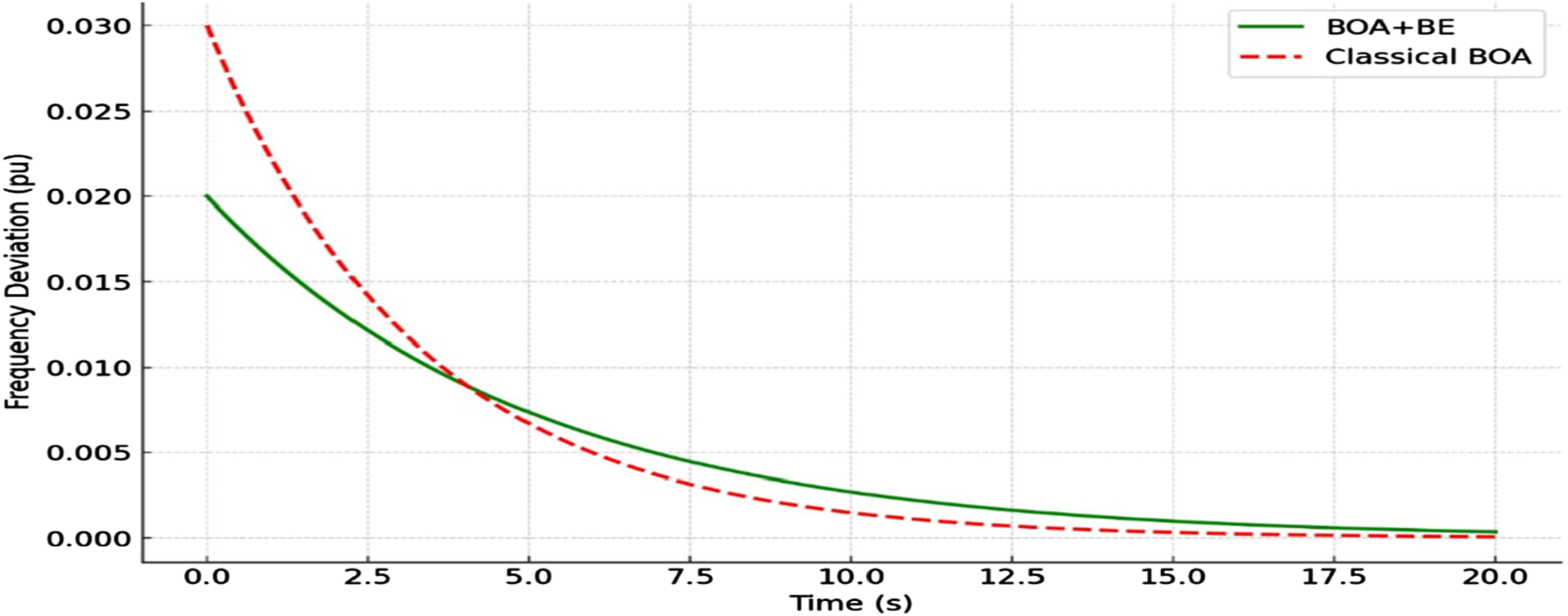
Case 3 response with load disturbance and noise
Figure 33 validates the robustness of BOA+BE in real-world conditions with noise and load disturbances. The system was subjected to both load disturbances and noise, simulating real-world conditions. The BOA+BE approach demonstrated superior robustness, minimizing oscillations and maintaining stability despite the presence of noise and fluctuating loads. Compared to the traditional BOA, BOA+BE was able to adapt in real-time, offering a smoother response and reducing the impact of external disturbances. This highlights the enhanced resilience of the BOA+BE method in noisy and dynamic environments, making it a more reliable solution for microgrid frequency control. Response with load disturbance and noise.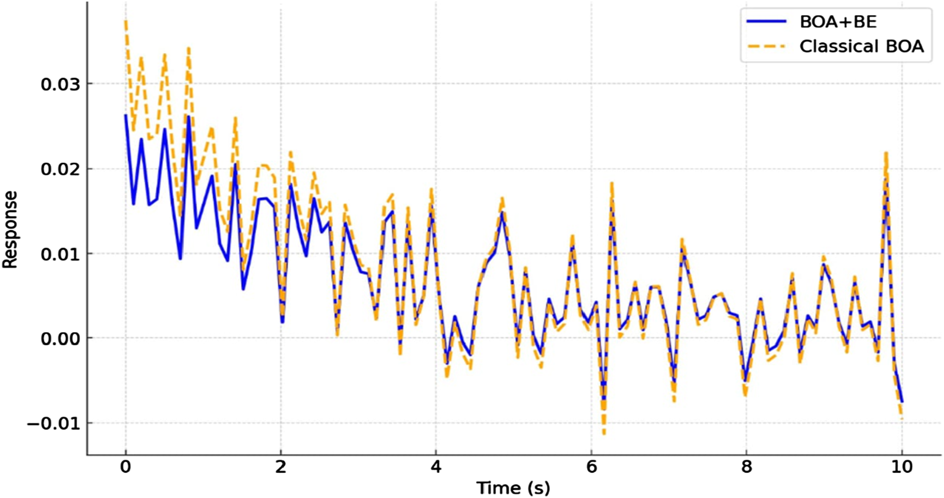
Conclusion
This paper presents an adaptive control strategy based on a modified Bat Optimization Algorithm (BOA) enhanced with the Balloon Effect (BE), applied to DC motor position control and microgrid frequency regulation. The proposed BOA +BE method dynamically adjusts optimization parameters, improving system adaptability compared to conventional BOA and other optimization techniques. Simulation and experimental results confirm that BOA +BE significantly reduces settling time, minimizes overshoot, and enhances energy efficiency, making it a reliable approach for real-time control in dynamic electrical systems. While the proposed method demonstrates clear advantages, certain limitations should be considered. The integration of BE increases computational complexity, which may affect real-time implementation in high-speed systems. Additionally, the effectiveness of BOA +BE relies on proper initial parameter tuning, as poor selection may lead to slower convergence. Furthermore, while the method enhances disturbance rejection, its performance in highly nonlinear or unpredictable environments requires further exploration. An important aspect analyzed in this study is the stability of the system under the proposed BOA +BE framework. The method ensures improved stability by dynamically adapting control parameters, effectively mitigating oscillations and disturbances. The closed-loop system response confirms that BOA +BE enhances robustness against parameter variations and external uncertainties, contributing to a more stable control system. Future work could further investigate formal stability proofs and Lyapunov-based analysis to mathematically validate the stability guarantees observed in the experimental results.
Future research will focus on optimizing computational efficiency, expanding its application to more complex industrial control scenarios, and validating its performance in real-time embedded systems to ensure broader applicability in smart grid and automation technologies.
Footnotes
Acknowledgements
The Researchers would like to thank the Deanship of Graduate Studies and Scientific Research at Qassim University for financial support (QU-APC-2025)
Funding
The authors disclosed receipt of the following financial support for the research, authorship, and/or publication of this article: Qassim University, QU-APC-2025.
Declaration of conflicting interests
The authors declared no potential conflicts of interest with respect to the research, authorship, and/or publication of this article.