
Abstract
During the mass transfer process of micro-LEDs, equipment may be affected by low-frequency vibrations, leading to issues such as poor chip alignment accuracy and reduced yield rates. Thus, there is an increasingly urgent demand for effective vibration control technologies in the mass transfer process of micro-LED panels. To this end, considering both active and passive vibration reduction techniques’ advantages and disadvantages, a novel device that combines momentum wheels with pendulum dampers has been proposed. The dynamic principles underlying its operation are then presented, followed by derived control schemes. Subsequently, the system’s vibration reduction performance is simulated in multi-body simulations to verify their accuracy, while multiple dynamical parameters of the control system are tested experimentally. In these tests, the rise time was found to be 0.128 s, the overshoot percentage was 54%, and the settling time was 1.6 s. Experimental results on a long rod structure validate the device’s vibration reduction effectiveness under external excitation conditions. The device with pendulum dampers reduced amplitude by 55% compared to that without any device. Momentum wheels decreased system amplitude by 62% compared to that without any device. The combination of momentum wheel and pendulum damper reduces the amplitude of the system by 96% compared to an empty rod. Experimental results of the prototype closely match those from multi-body simulations: rise time = 0.176 s, peak time = 0.305 s, and maximum overshoot = 56.3%. The experimental results demonstrate that this device effectively reduces vibrations and incorporating pendulum dampers enhances momentum wheels’ vibration reduction effectiveness.
Introduction
The manufacturing of precision instruments is widely affected by low-frequency vibrations, particularly during the mass transfer process of micro LEDs.1–3 Equipment subjected to such vibrations may result in issues like poor alignment precision and low yield rates of chips. Consequently, there is a growing demand for effective vibration control technologies in the manufacturing field of micro-LED panels.
At the forefront of vibration control strategies, there are mainly three approaches4–13: active, passive, and hybrid control schemes. Traditional passive vibration control has achieved certain successes in the field of vibration control, such as tuned mass dampers and isolation techniques. Passive vibration control offers advantages such as simplicity, reliability, and low cost. However, passive vibration control can only provide effective vibration control within a certain frequency range and cannot adapt to changes in the system’s vibration spectrum.
Jiang et al. 14 designed and proposed an innovative vibration isolation-absorption integrated system, which combines passive control strategies with nonlinear control mechanisms. This system greatly enhances overall vibration suppression efficiency through their combined effects. Masnata et al. 15 studied a non-traditional tuned liquid column damper to control lateral displacement of base-isolated structures during seismic events. In contrast, active vibration control schemes can adapt to vibration conditions under different operating conditions and environments. However, they also have disadvantages such as complexity and high maintenance costs. Zhang and Wang 16 utilized an active rotational inertia drive system to control the swing vibration of a suspension structure. Deng et al. 17 designed a magnetorheological damper to enhance the controllability of small-amplitude and mid-to-high frequency vibrations in a magnetorheological full satellite, effectively reducing satellite resonance peaks.
Despite significant advancements in vibration control research, suppressing low-frequency vibrations—especially those with large amplitudes—remains a persistent challenge. 13 These vibrations require both precise control and efficient energy use, which traditional methods often fail to deliver. Active control techniques are limited by high energy demands and cost, while passive methods suffer from narrow bandwidth and poor adaptability. To address these limitations, multifunctional damper-based technologies have been developed. For example, magnetically suspended momentum wheels enable adjustable damping for low-frequency suppression, 18 while frequency-tunable dampers based on magnetorheological elastomers provide adaptable passive control. 19 These approaches demonstrate improved efficiency and broader applicability in low-frequency vibration scenarios.
Momentum wheels are commonly used devices for adjusting spacecraft attitude,20–22 known for their efficiency and reliability. Pendulum-tuned mass dampers (PTMDs), on the other hand, are widely applied in civil engineering to passively reduce structural vibrations in systems such as high-rise buildings and bridges.23–25 However, the damping effectiveness of PTMDs is typically optimal only when the excitation frequency matches the fundamental frequency of the host structure, making them less effective across broader frequency ranges. In contrast, momentum wheels offer active control capabilities that can extend vibration suppression beyond the narrow operational range of PTMDs.
This study proposes a novel vibration reduction device that, for the first time, integrates momentum wheels with pendulum-tuned mass dampers to overcome the limitations of conventional single-mode systems. Given the significant engineering challenges involved in directly implementing the device within the micro-LED production process—such as manufacturing complexity and stringent precision requirements—a representative long-rod structure is used for experimental validation. Such structures are commonly found in various stages of micro-LED fabrication, including slender mechanical arms or pick-and-place units in chip transfer equipment, which exhibit similar dynamic characteristics. Evaluating the damping performance on this type of structure allows us to demonstrate the feasibility and potential applicability of the proposed method in practical micro-LED scenarios. The active-passive hybrid mechanism leverages the frequency adaptability of momentum wheels to compensate for the limited bandwidth of PTMDs, thereby enhancing low-frequency vibration control. Furthermore, a decoupled control strategy based on Lagrangian mechanics is developed to coordinate the dynamics of the momentum wheel and PTMD subsystems, resulting in improved active damping performance.
The remainder of the paper is organized as follows: Section 2 introduces the dynamic principles and control equations of the proposed device. Section 3 presents the evaluation of its dynamic performance through multi-body simulations. Section 4 describes the experimental setup, followed by Section 5, which discusses the experimental results. The findings demonstrate that the proposed device significantly reduces the swing amplitude in long rod structures and that the integration of PTMDs notably enhances the vibration reduction performance of conventional momentum wheel configurations.
Principle and dynamics modeling of the device
In this section, the principle of the momentum wheel and the pendulum-tuned mass damping device and their dynamic modeling were present.
Principle of momentum wheel and pendulum tuned mass damper
In Figure 1, Schematic diagram of active vibration suppression device.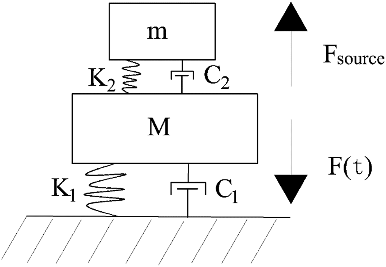
For momentum wheels, when the long rod structure is disturbed by external forces, an overturning moment will be formed with the supporting force. The momentum wheel needs to provide a moment to the long rod structure in the opposite direction of equal magnitude, based on the data provided by sensors and appropriate algorithms.
The pendulum-tuned mass damper is often simplified into the theoretical model shown in Figure 2. When the system is subjected to external excitation Theoretical model of pendulum tuned mass damping device. Response diagram of oscillator amplitude as a function of excitation frequency.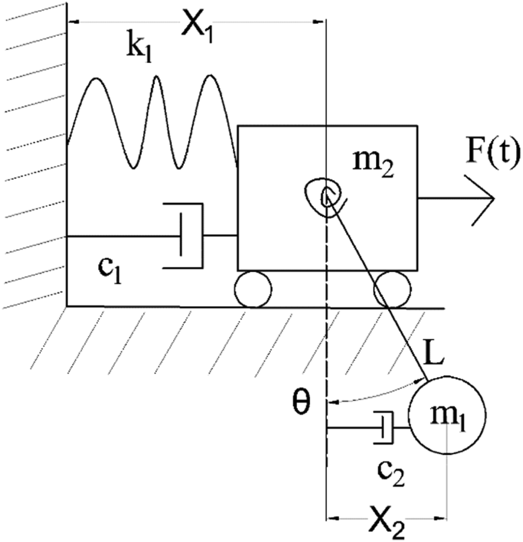
When
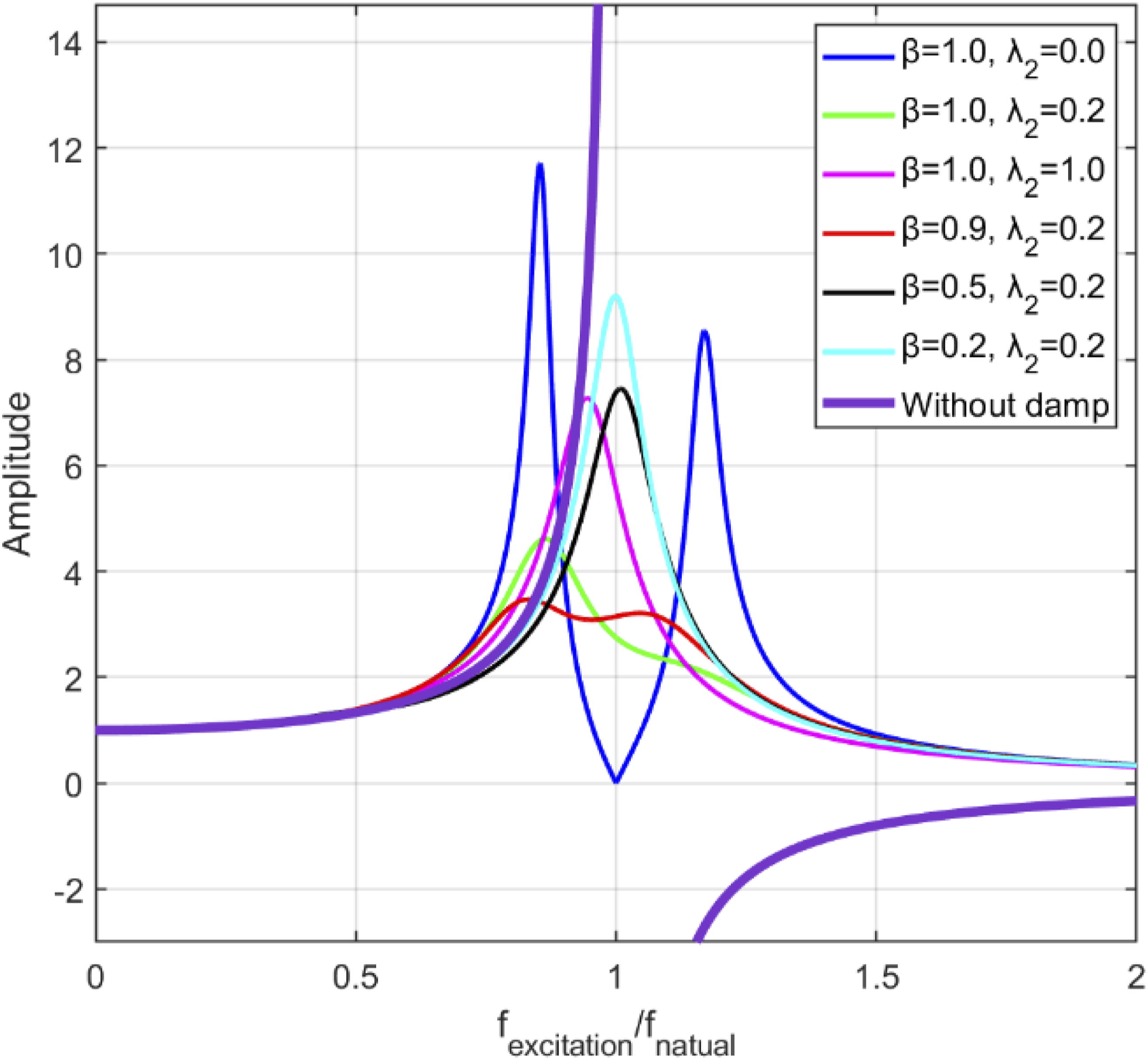
It can be observed that the pendulum-tuned mass damper (PTMD) exhibits optimal damping performance when the ratio between the excitation frequency and the pendulum’s natural frequency (i.e., fexcitation/fnatural) is close to 1. However, outside this narrow frequency range, its vibration reduction capability significantly diminishes. To address this limitation and improve performance across a broader frequency spectrum, a momentum wheel is introduced to complement the PTMD by actively suppressing vibrations where the PTMD alone is less effective.
Dynamic modeling of plant
The device consists of two momentum wheels positioned at a 90° angle in the inertial reference frame (X, Y, Z). One momentum wheel is responsible for absorbing angular momentum in the X-axis direction of the system, while the other momentum wheel is responsible for absorbing angular momentum in the Y-axis direction of the system. Pendulum-tuned mass dampers are mounted above the two momentum wheels. The entire device is installed on a long-bar structure. The schematic diagram of the device is shown in Figure 4. Schematic diagram of the device composed of momentum wheel and pendulum damper.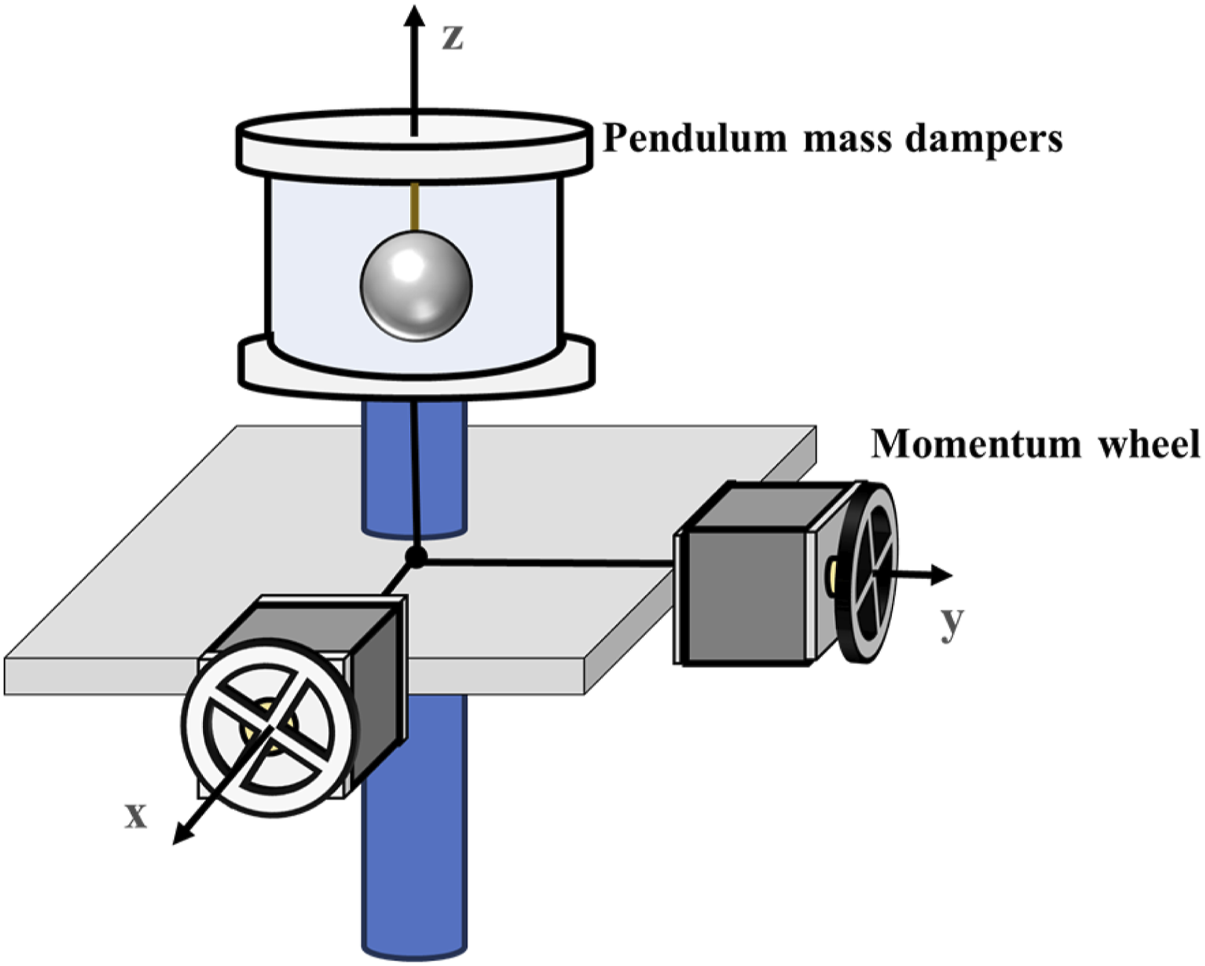
To compensate for the limited damping performance of the PTMD in frequency ranges where its effectiveness is reduced, a momentum wheel is introduced to provide supplementary vibration suppression. The motion of the PTMD can interfere with the operation of the momentum wheel. Therefore, a control strategy that accounts for the dynamic influence of the PTMD is required. To this end, a dynamic model incorporating the motion of the PTMD is developed to enable coordinated control between the two systems.
The mechanical system composed of momentum wheels and pendulum-tuned mass dampers is equivalent in the X-Z plane and Y-Z plane. By selecting one of these planes for analysis, the simplified mechanical model depicted in Figure 5 is obtained. Simplified mechanical model diagram.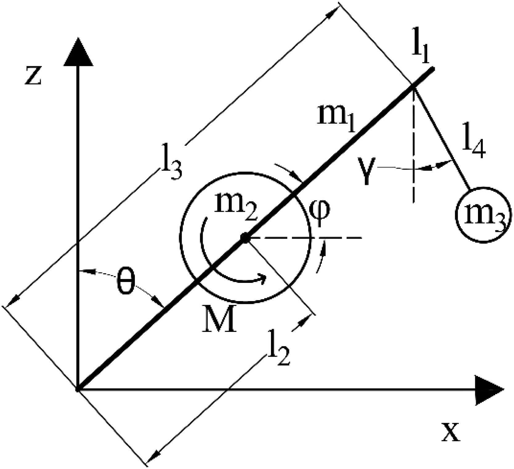
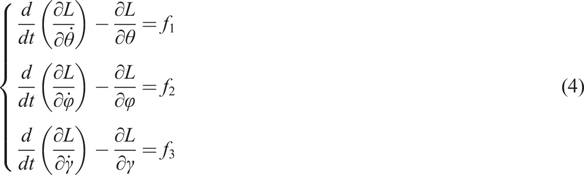
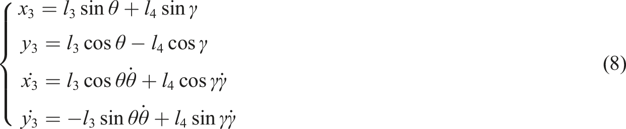
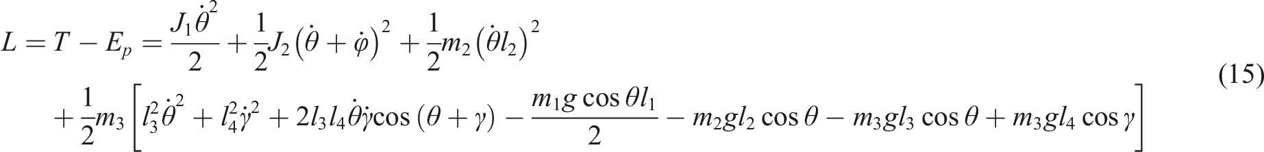
The model consists of a uniform rod, a momentum wheel, and a pendulum-tuned mass damper. The rod has a mass of m1, a length of l1, and a moment of inertia of J1. The momentum wheel has a mass of m2, with its center at a distance l2 from the origin, and a moment of inertia of J2 about its rotation axis. The output torque is denoted as M. The pendulum-tuned mass damper has a mass block with mass m3, centered at coordinates (x3, y3). The distance from the top of the damper to the bottom of the rod is l3, and the length of the damper’s pendulum string is l4. In this model, the clockwise direction is considered as the positive direction of rotation. According to Lagrange equation

The kinetic energy of the rod and momentum wheel is


The kinetic energy of pendulum tuned mass damper is

Then it follows that


The potential energy of the rod, momentum wheel, and pendulum-tuned mass damper is


The total potential energy of the system is

Taking the generalized coordinate


Taking the generalized coordinate

By taking the generalized coordinate

Due to the small swinging angles
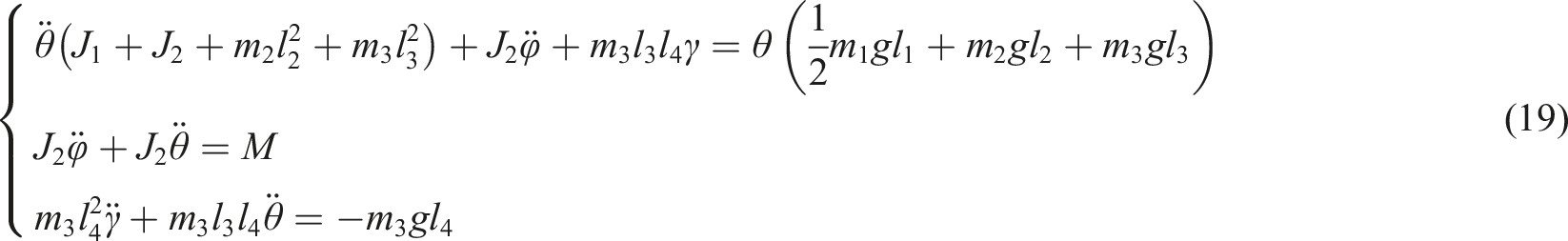
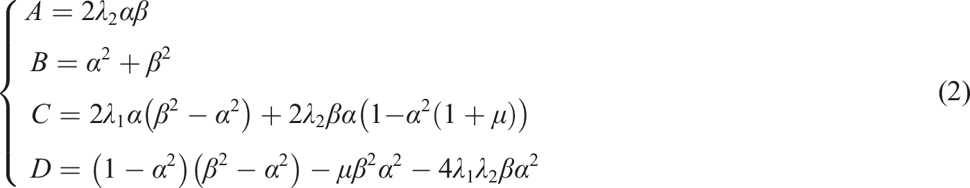
Integrating the equations above

Making
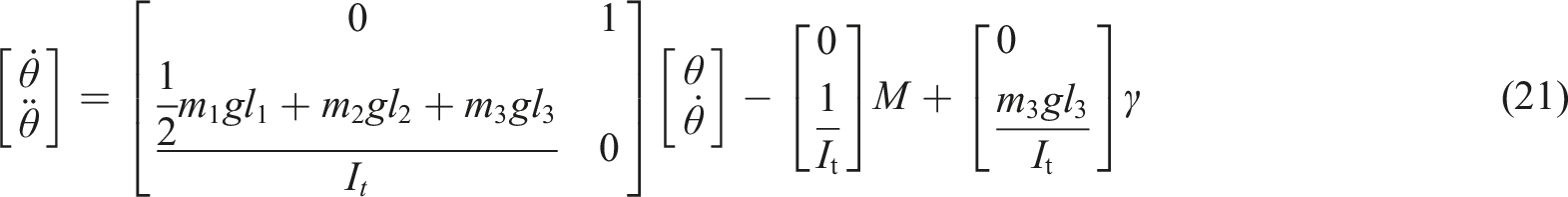
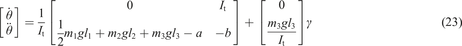
By taking M as the input and

2.2 Design of momentum wheel control scheme
In this control system,
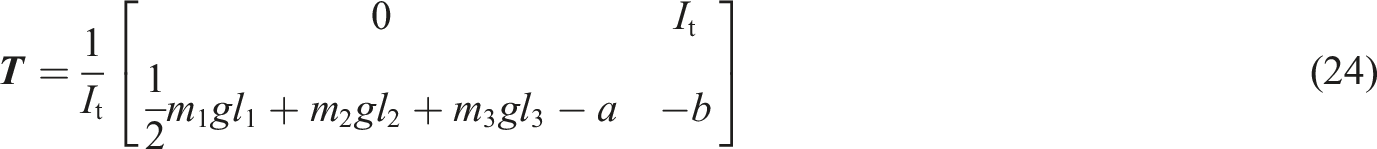
By adjusting the values of

The two equations are combined as follows
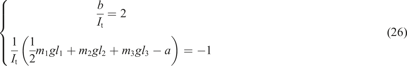
It is obtained:

The model analysis in this paper assumes that the system is in a free motion state, and in order to obtain a concise control equation, several approximations have been made. As a result, there is some deviation between the control model and the actual experiment. To address this, the paper introduces a stable and reliable PID control scheme based on formula (27) to compensate for the deviation between the physical modeling and the actual situation. The output torque

The PID parameters
Multibody simulation verification
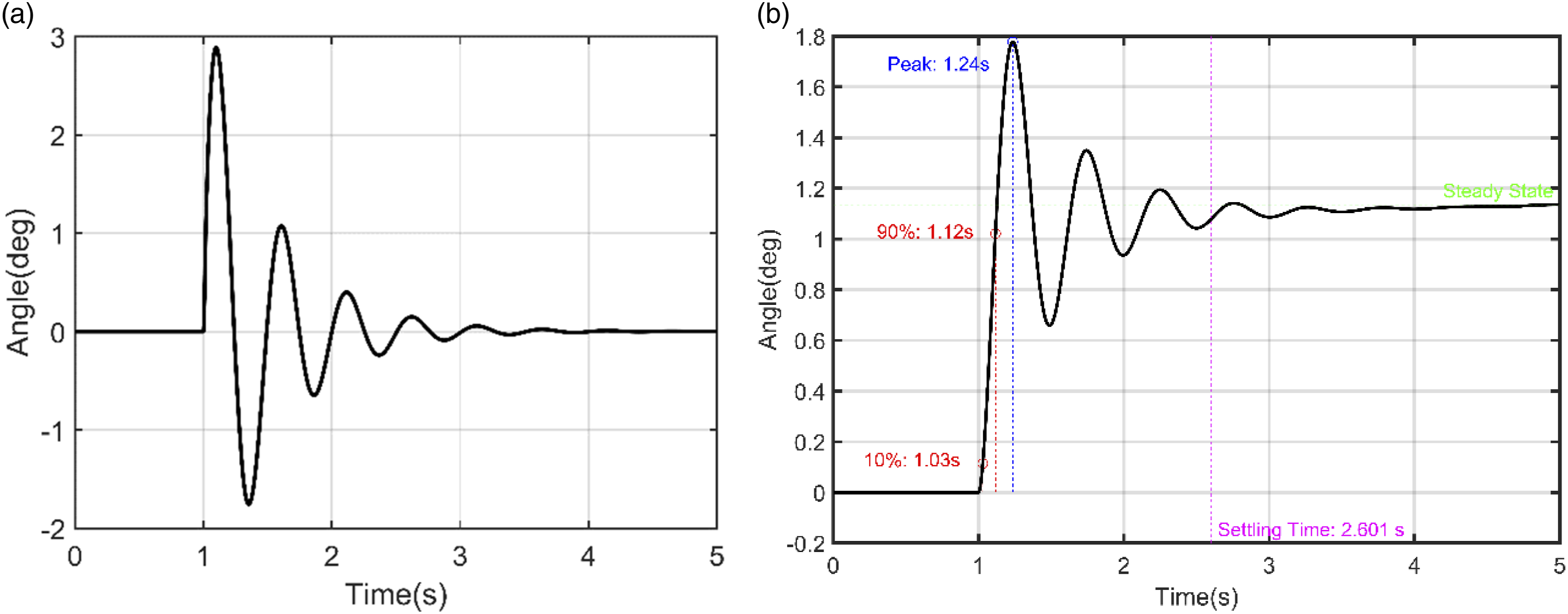
The paper utilizes the multi-body module in Simulink to perform simulation experiments on the multi-body dynamics and control of the device. When the system is subjected to pulse and step signals as inputs, the system’s time-domain response is as follows:
Key information regarding the dynamic characteristics of the control system is obtained from Figure 6. An impulse input is applied to the system (as shown in Figure 6(a)), and the Fourier transform of the response yields the transfer function, indicating that the system behaves as a second-order, time-invariant system. Upon examining the step response resulting from a unit-step input (Figure 6(b)), the following observations are made: (1) The damping ratio (2) The rise time (3) The peak time, referring to the time at which the response reaches its maximum value before declining, is approximately 0.244 s. (4) The maximum overshoot is relatively high (54%), indicating moderate oscillatory behavior in the output signal. (5) The settling time, defined as the time required for the system to remain within a certain percentage (typically 2% or 5%) of its final value, is approximately 1.61 s. Time domain response diagram of the system. (a)impulse signal; (b)step signal.
To validate the vibration reduction effect of the pendulum-tuned mass damper (PTMD) on the system, it is necessary to compare the time-domain and frequency-domain responses of the system with and without PTMD in the multi-body simulation.
When the system is subjected to a sinusoidal excitation signal, the time-domain and frequency-domain responses are shown in Figures 7(a) and (b), respectively. As observed in Figure 7(a) the system equipped with a PTMD exhibits a lower oscillation amplitude compared to the system without it. Additionally, in the frequency spectrum shown in Figure 7(b), the system without a PTMD displays two distinct peaks, whereas the system with a PTMD shows only a single peak with reduced amplitude. Response of the system to sinusoidal excitation signals. (a) in time domain; (b) in frequency domain.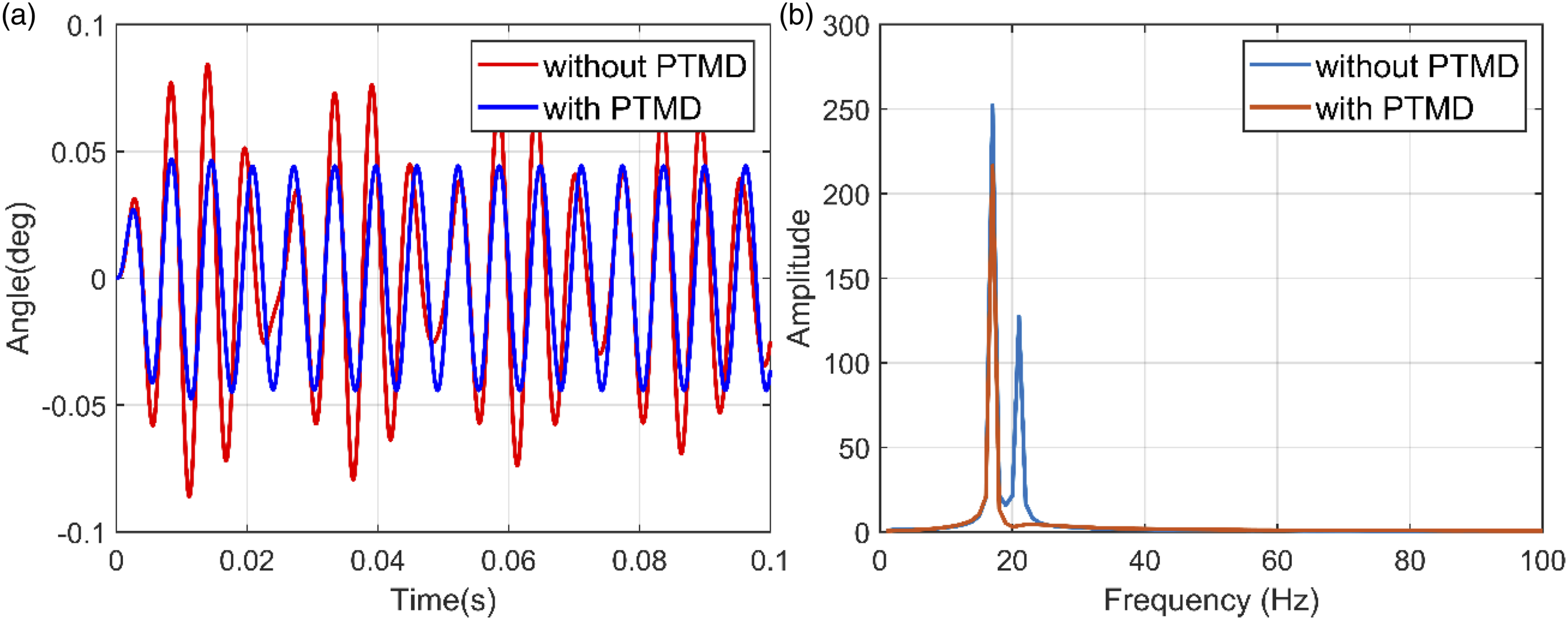
The maximum average swing amplitude in Figure 7(a) is 0.046°, while the system’s average maximum swing amplitude is 0.063° when the pendulum-tuned mass damper is not present. The addition of the pendulum-tuned mass damper results in a 27% reduction in the average maximum swing amplitude.
Under the same random signal disturbance, the time-domain and frequency-domain responses of the system are depicted in Figures 8(a) and (b), respectively. The results indicate that the system equipped with the PTMD exhibits a significantly smaller amplitude compared to the system without it, as shown in Figure 8(a). This trend is further confirmed by the frequency-domain plot in Figure 8(b). Responses of the system to random noise. (a) in time domain; (b) in frequency domain.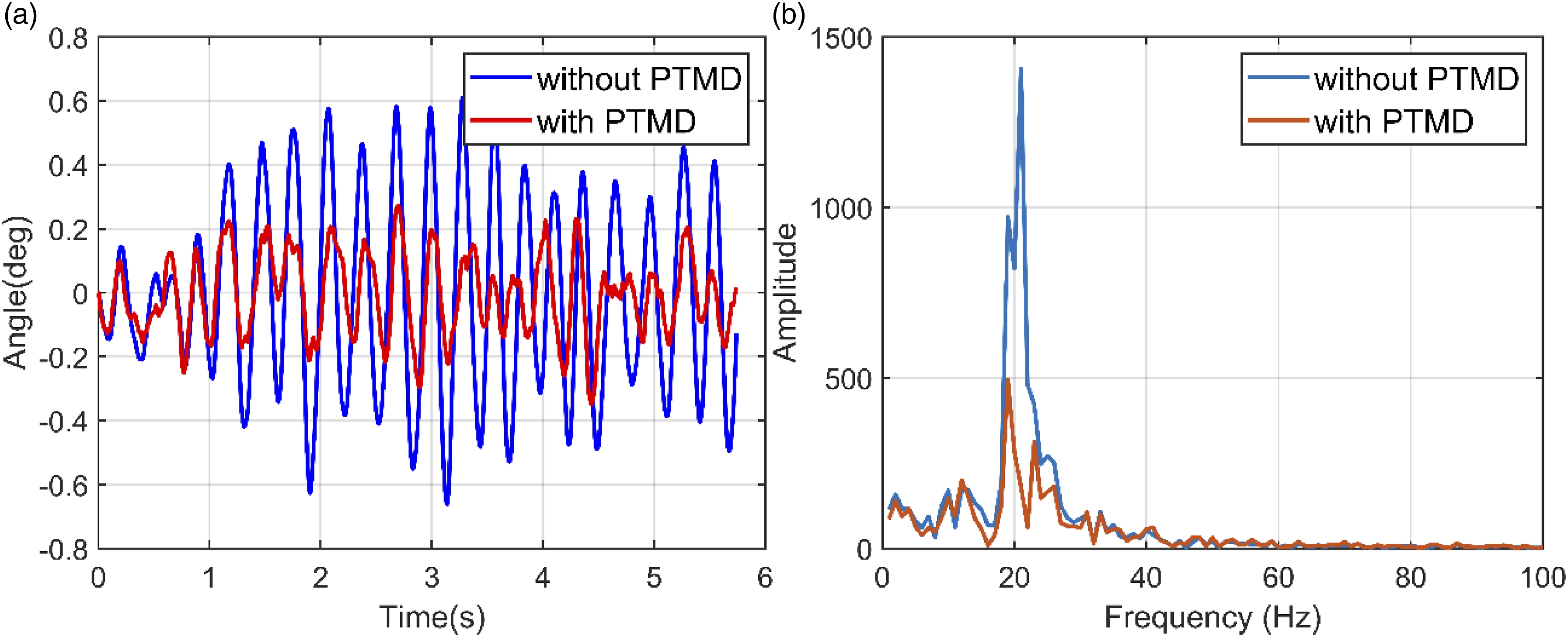
Simulink simulation results indicate that the system can effectively reduce amplitude in the low-frequency domain. From the time-domain graph shown in Figure 7(a)) and Figure 8(a), it can be concluded that the addition of the pendulum damping device has enhances the system’s vibration reduction effect when facing both regular sinusoidal and random signals. This is further validated by the frequency-domain graph shown in Figure 7(b) and Figure 8(b), where a reduction in components across all frequencies is observed, with the effect being more pronounced under random excitation.
Experiment on vibration elimination ability of equipment
The assembly of the device
The device is designed based on the theoretical framework outlined in Section 2, and its physical configuration is illustrated in Figure 9. To align the device’s center of gravity with the ground reaction force, additional counterweights are incorporated. The system employs an MPU6050 as the primary sensor to acquire the rod’s angular position. The MPU6050 is fixed onto the device, and as the angle between the device and the ground changes, the sensor captures the corresponding values. The MPU6050 is a 6-axis attitude sensor made by TDK InvenSense, with a gyroscope sampling frequency of up to 8 kHz and a range of ±250°/sec. The main control chip used to control the stepper motor rotation is the STM32F103RCT6, which is a high-density performance series ARM Cortex-M3 32-bit microcontroller developed by STMicroelectronics, with a maximum operating frequency of 72 MHz. The stepper motor used is the 573S10-LS three-phase hybrid stepper motor manufactured by LEADSHINE, with a maximum output torque of 0.9Nm. Physical view of the device.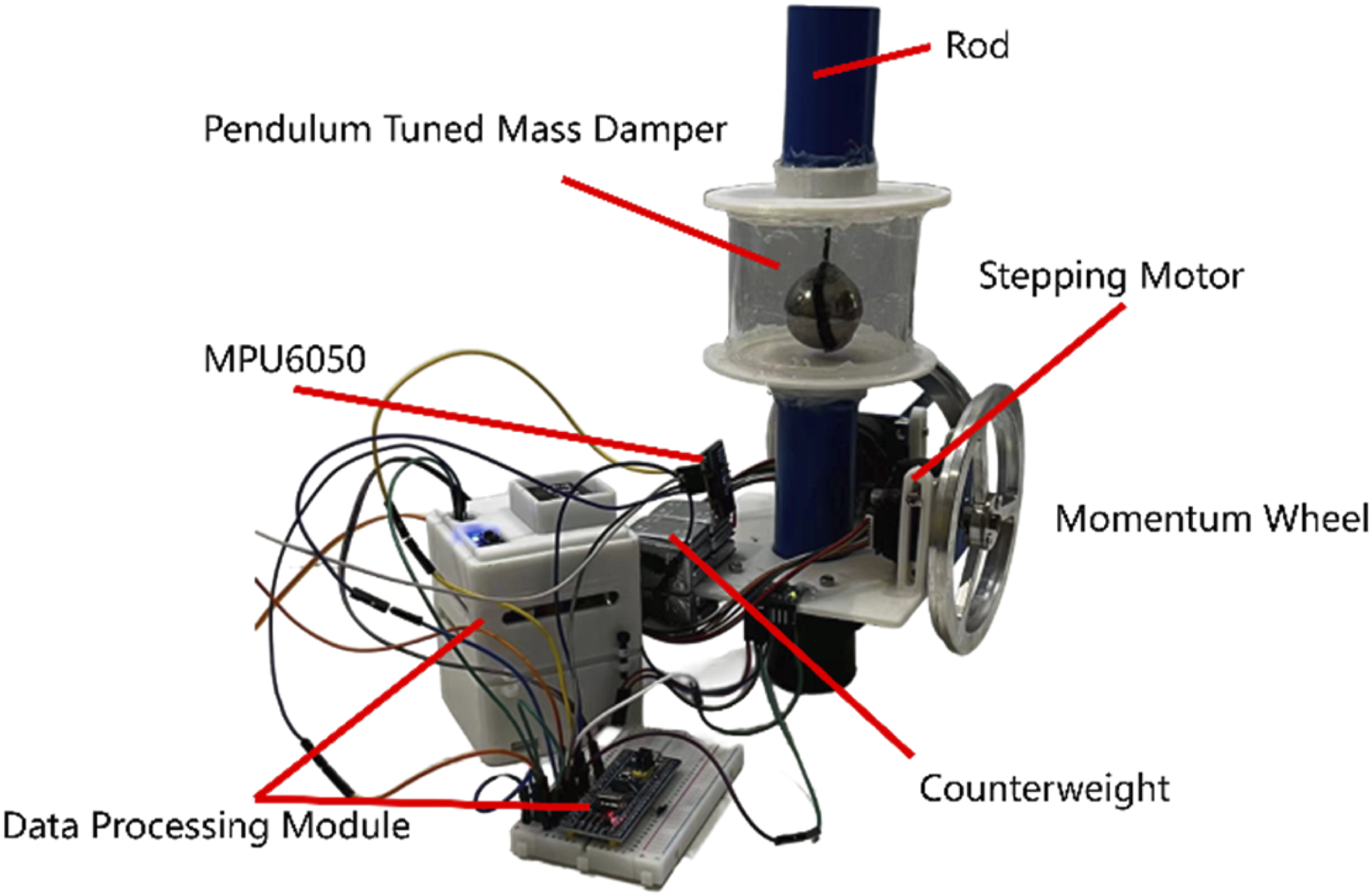
To evaluate the device’s resistance to vibration, a vibration platform was created using a motor and a lead screw (shown in Figure 10(a)). The device was positioned on top of the vibration platform, and the motor and lead screw were used to simulate vibration through repeated movement. The angle data of the rod was obtained using MPU6050. In addition, to assess the dynamic performance of the control system, a crank-slider mechanism was fabricated to generate reciprocating motion (shown in Figure 10(b)). This mechanism used a lever mounted on the slider to impact the device rapidly, simulating the input of pulse signals. Similarly, the angle signal of the rod was captured using MPU6050. Schematic diagram of crank slider mechanism and vibration platform. (a) Vibration platform composed of ball screw and stepping motor; (b) crank slider device powered by brushless-motor and gear set.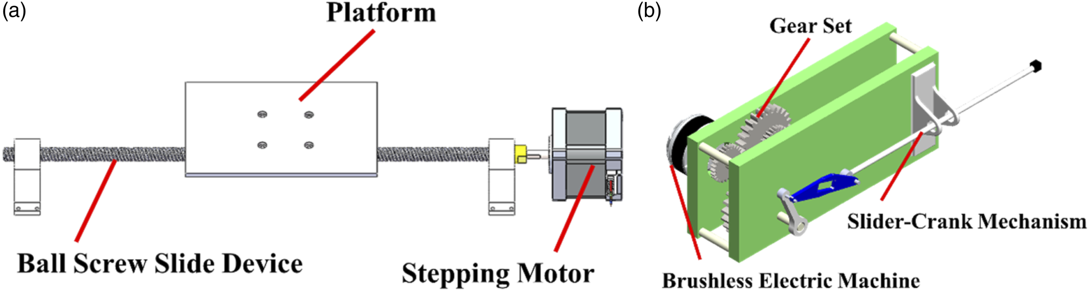
Result
This section presents a comparison of the experimental findings obtained from the device under different configurations, including setups with or without a momentum wheel and with or without a pendulum damper. Additionally, a comparison is conducted between the system equipped with the device and one lacking it entirely.
The time-domain and frequency-domain responses of both systems—one with and the other without momentum wheels—can be visualized in Figures 11(a) and (b) respectively. As illustrated in Figure 11(a), the inclusion of momentum wheels leads to a significant reduction in amplitude, consistent with the trends observed in previous experiments. In Figure 11(b), the frequency-domain plot shows that the amplitudes are substantially reduced across nearly all frequencies when momentum wheels are employed. Most notably, this setup ensures relatively stable amplitudes across a wide range of frequencies, demonstrating strong robustness to frequency variations. In contrast, without momentum wheels, the system exhibits pronounced amplitude fluctuations across the frequency spectrum, particularly in the low-frequency range. This finding suggests that the system is more susceptible to performance degradation under frequency shifts when momentum wheels are absent. Response of the system with or without momentum wheel. (a) in time domain; (b) in frequency domain.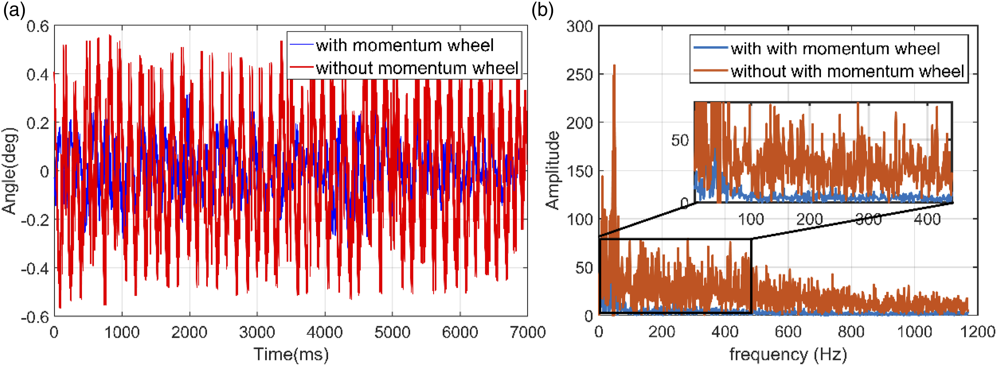
The time-domain and frequency-domain responses of the system with and without pendulum-tuned mass dampers are shown in Figures 12(a) and (b), respectively. As shown in Figure 12(a), the damper effectively reduces the system’s vibration amplitude, consistent with the earlier findings obtained from the Simulink simulation. Figure 12(b) reveals significant differences in system response across different frequencies, with a noticeable reduction in amplitude when the damper is present. Response of the system with or without damping device. (a) in time domain; (b) in frequency domain.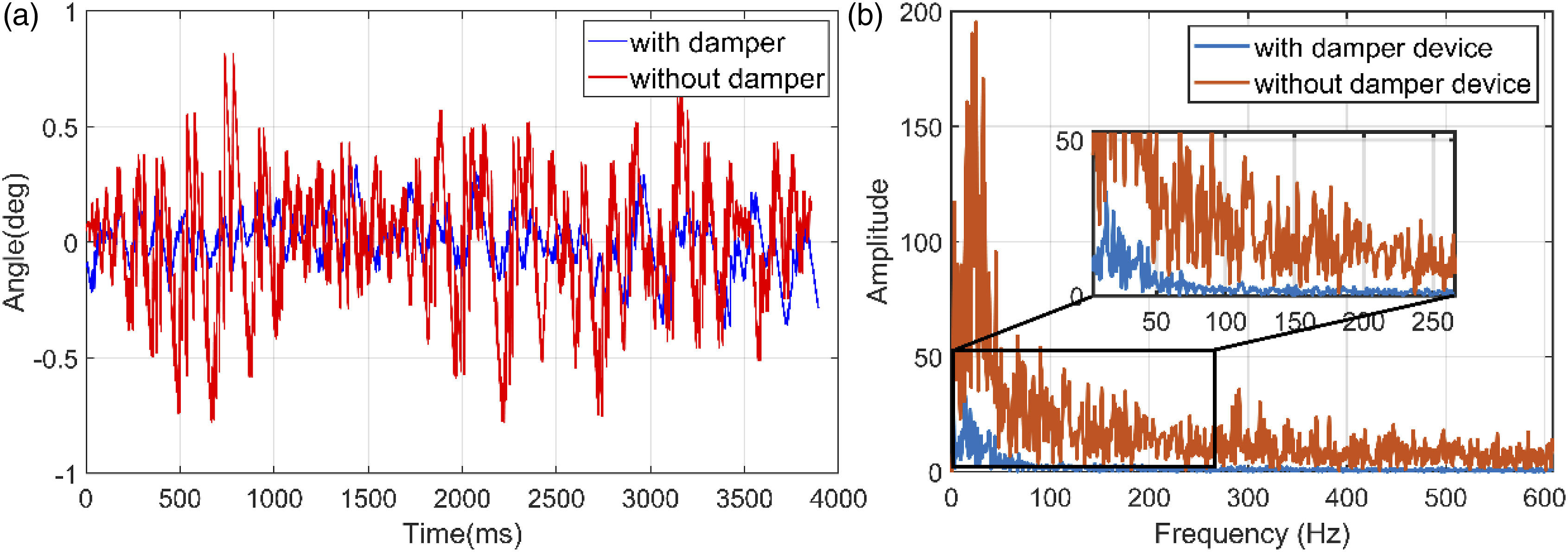
The time-domain and frequency-domain responses of the system with and without the device are shown in Figures 13(a) and (b), respectively. As illustrated in Figure 13(a), the device significantly reduces the system’s oscillation amplitude, while the frequency components in Figure 13(b) appear more stable and less dispersed. (Table 1) provides a quantitative analysis of the average swing amplitudes under various conditions. Response of the system with or without device. (a) in time domain; (b) in frequency domain. Comparison table of damping effect of devices.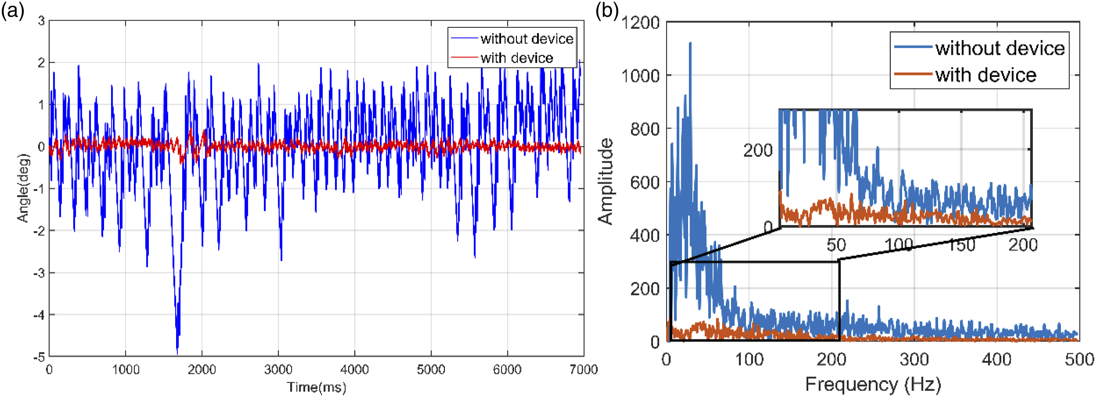
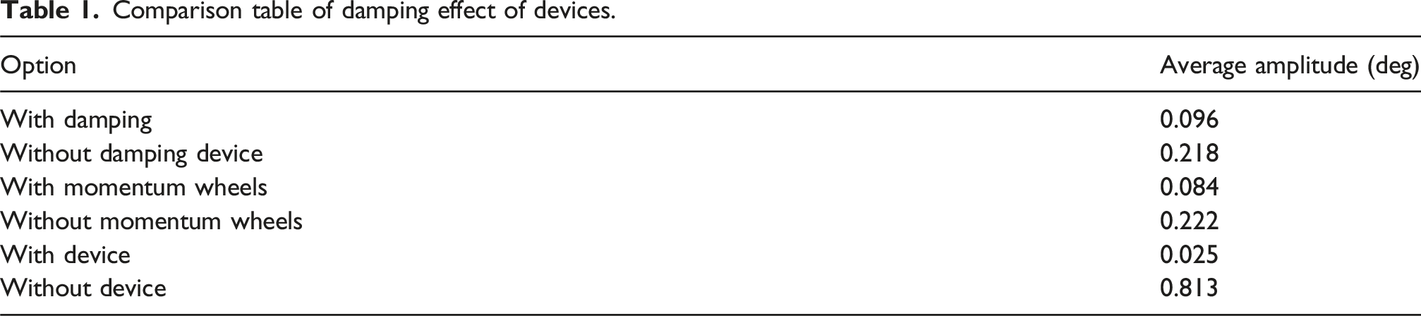
By comparing the experimental data presented in (Table 1), it is observed that the amplitude of the long rod structure equipped with a momentum wheel is significantly smaller than that without a momentum wheel under the same conditions, with a reduction of approximately 62%. Similarly, the presence of a pendulum-tuned mass damping device results in a notable amplitude reduction of approximately 55%. The installation of either component leads to a substantial decrease in vibration amplitude, with a reduction of up to 96% compared to the scenario without any installation. These findings demonstrate that the devices are highly effective in reducing the oscillatory motion of the rods.
Due to the cumulative effect of speed increase in momentum wheels (which are constrained by the motor’s maximum speed), utilizing step signals for measuring the system dynamic performance may not produce accurate results. Consequently, this paper employs a crank-slider mechanism to simulate pulse signals for evaluating the system’s dynamics. The experimental findings are presented in Figure 14. From Figure 14, it is evident that the experimental setup exhibits a rise time of approximately 0.176 s and a peak time of about 0.305 s; further, an overshoot percentage of 56.3% has been observed. Time domain impulse response curve of the device.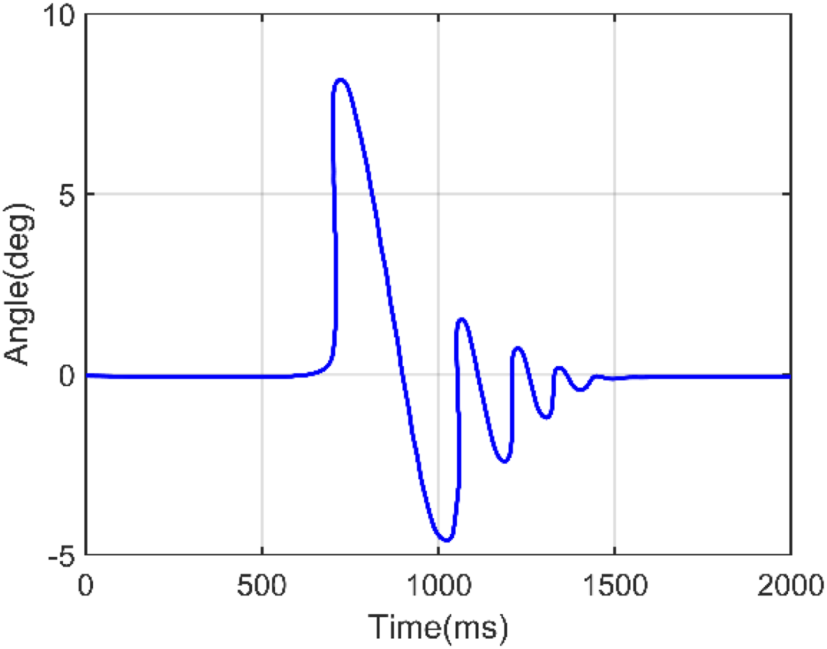
Conclusions
This study presents an innovative vibration reduction device that integrates a momentum wheel with a pendulum-tuned mass damper to address the challenge of suppressing large-amplitude, low-frequency vibrations. Experimental validation was conducted on a long-rod structure representative of slender components commonly found in micro-LED manufacturing equipment, such as robotic arms or pick-and-place units. The results show that the proposed hybrid system reduces oscillation amplitude by 96% under external excitation, significantly outperforming standalone configurations—55% reduction using only the pendulum damper and 62% using only the momentum wheel. Without a solid baseline, the system demonstrated stable dynamic performance, with a rise time of 0.176 s, peak time of 0.305 s, and a maximum overshoot of 56.3%, closely matching the multi-body simulation results. A decoupled control strategy based on Lagrangian analytical mechanics was developed to coordinate the active and passive elements, enhancing system adaptability across a broader frequency range. These findings confirm the effectiveness and practical relevance of the proposed device for vibration suppression in micro-LED production environments, where precision and stability are critical.
Future work will focus on addressing the inherent limitation of the momentum wheel device: when subjected to continuous disturbances in one direction, the momentum wheel loses its effectiveness in that direction due to the motor’s speed limit. Alternative devices or methods will be explored to replace the rotation of the momentum wheel.
Footnotes
Funding
The author(s) disclosed receipt of the following financial support for the research, authorship, and/or publication of this article: This research was funded by Natural Science Foundation of China under Grant 52305597, Science and Technology Projects in Guangzhou under Grant 2023A04J1611, and funded by State Key Laboratory of Precision Electronic Manufacturing Technology and Equipment under Grant JMDZ202313, Engineering Technology Center of Guangdong General University under Grant 2022GCZX005, and by the R&D projects in key areas of Huizhou in 2024 under Research and application of key technologies of high-performance Micro LED display Grant 2024BQ010008.
Declaration of conflicting interests
The author(s) declared no potential conflicts of interest with respect to the research, authorship, and/or publication of this article.