
Abstract
In this study, the dynamic response of single degree-of-freedom (SDOF) systems equipped with an inerter or a clutching inerter damper (CID) under harmonic force or base excitation is investigated. Under harmonic force excitation, an inerter must work with an appropriate damping element to prevent the kinetic energy it absorbs from being returned to the primary system. However, the addition of the damping element introduces extra damping force, which can deteriorate the force transmissibility within certain frequency ranges. In comparison, the piecewise nature of the CID effectively overcomes this limitation. Since this piecewiseness is a typical nonlinear feature, the averaging method is employed to solve the system response. The obtained approximate analytical solution is compared with the solution derived from the equivalent linearization method (ELM). It is found that the resonant frequency calculated by the ELM is significantly higher than the numerical solution for inertance
Keywords
Introduction
In recent years, with the continuous advancement of vibration control technology and the increasing demand for vibration suppression in equipment, a series of novel and effective vibration suppression devices and techniques have emerged.1–7 Among these, vibration damping devices based on the inerter have attracted significant attention across various fields due to their unique attributes.8,9 The inerter is a mechanical device with two terminals, where the force on each terminal has equal magnitude but in opposite directions and is directly proportional to the relative acceleration between the terminals. The proportionality constant between the force and the relative acceleration is called inertance or apparent mass and is measured in kilograms. Previous literature shows that similar mechanisms to the inerter were used in practical engineering in the 1990s.10,11 But the concept of the inerter was not introduced until 2002 by Smith, 12 where he described it as a two-terminal device analogous to the electrical capacitor in the force-current analogy.
Over the past few decades, the inerter has made significant strides in various fields, such as automotive engineering,13,14 aerospace engineering, 15 civil engineering,16–18 and vibration energy harvesting.19–23 One of the most successful examples is the application of the inerter in the suspension system of F1 racing cars, 13 which has been proven to significantly enhance vehicle performance. 14 The application of the inerter has contributed to innovative solutions for these classical problems. While the inerter has enhanced the performance of vibration control devices, it also exhibits certain inherent drawbacks, such as energy feedback to the primary system during operation24,25 and transient impact issues caused by motion reversal. 26 These drawbacks arise from the behavior of the inerter under relative motion, during which it rotates and accumulates a substantial amount of kinetic energy. As the relative motion across the inerter slows down, the attached flywheel also decelerates. However, the kinetic energy stored in the flywheel resists this deceleration, causing the inerter to drive the displacement of the system, thereby introducing additional dynamic effects.
To address these shortcomings, scholars have undertaken structural innovations for the inerter, with one notable approach being the integration of a clutch mechanism.24,25 In 2016, Makris and Kampas 25 proposed a device with two sets of flywheels and one-way clutches, similar to the ratchet mechanism in a bicycle. The working directions of these two sets of flywheels are opposite, allowing force transmission only when the directions of the relative velocity and acceleration are consistent. Wang and Sun 27 termed this device as the CID and evaluated the response reduction effect of linear SDOF systems with a CID through parametric analysis under harmonic excitations and real earthquake records. Javidialesaadi and Wierschem 24 proposed a novel rotational inertia device termed as one-directional rotational inertia viscous damper (ODRIVD) for passive structural control, and studied it as an attachment to SDOF systems. Essentially, ODRIVD is also a CID. Li et al. 26 designed and analyzed a ball-screw inerter with mechanical diodes, conducting experiments to investigate the relationships among the inertance, the exciting force, and the vibration of the housing. Thiers-Moggia and Málaga-Chuquitaype 28 compared the effects of inerter and CID on the rigid rocking blocks. They observed that the introduction of inerter effectively reduced the overturning probability due to the size effects of the rocking behavior. Furthermore, CID can further improve the general overturning resistance of the block, but it has an adverse impact on the reduction of acceleration. Makris and Moghimi 17 utilized a CID to regulate the seismic response of a two degree-of-freedom (DOF) system and examined the extent to which a compliant support of the inerter affected the dynamics of the structure. Jangid 29 assessed the seismic performance of isolated bridges equipped with a CID, noting that the nonlinear force proportional to acceleration generated by the CID effectively suppresses response fluctuations in bridges under seismic excitation. Through iterative spectral analysis, it was demonstrated that optimal vibration control is achieved with a specific inertance value, which minimizes the absolute acceleration of the bridge deck. Another study by Jangid 30 examined the performance of base-isolated structures with a CID, identifying optimal inertance values through comparisons of stochastic and real earthquake responses. This analysis highlighted the beneficial effects of the CID in reducing both displacement and acceleration responses, supporting its application for enhancing seismic resilience in complex isolation systems. Wang et al. 31 proposed a clutching inerter enhanced tuned mass damper (TMDCI), which can be regarded as a combination of a tuned mass damper with inerter (TMDI) and a CID, and conducted performance analysis and optimization on SDOF and three DOF steel structures as the primary systems. Subsequently, based on the analytical investigation of standalone TMDCIs, Zheng and Li 32 proposed an innovative reducer clutching inerter damper (RCID) by combining a reducer with the clutching inerter damper to improve its inertance. Via numerical simulations and experimental validation, it was demonstrated that the RCID exhibits superior vibration damping performance compared to conventional inerter-based systems. Cupp and Wierschem 33 investigated the performance of a CID integrated with base isolation systems (BISs) in multi-degree-of-freedom (MDOF) systems to enhance isolation performance and reduce base displacements. The findings suggested that the BIS with CID outperformed other configurations and highlighted the diminishing returns of increased rotational inertance.
However, due to the intrinsic strong nonlinearity introduced by the piecewise and non-smooth behavior of one-way clutches, previous studies have predominantly focused on numerical and experimental research. While commonly used approximation methods, such as the ELM,27,30,34 simplified the analysis, they often resulted in an overestimation of the resonant frequency. Therefore, to better reveal the intrinsic characteristics and control mechanisms of the CID, this study employs the averaging method to derive approximate analytical solutions for a SDOF system with a CID under harmonic force and base excitations. These solutions are then compared with those of a SDOF system equipped with an inerter, thereby elucidating the distinctions between the effects of a CID and an inerter.
System responses under harmonic force excitation
SDOF system with an inerter under harmonic force
Up to now, there are mainly three types of inerter, that is the rack-pinion inerter, the ball-screw inerter,13,35 and the hydraulic inerter.
36
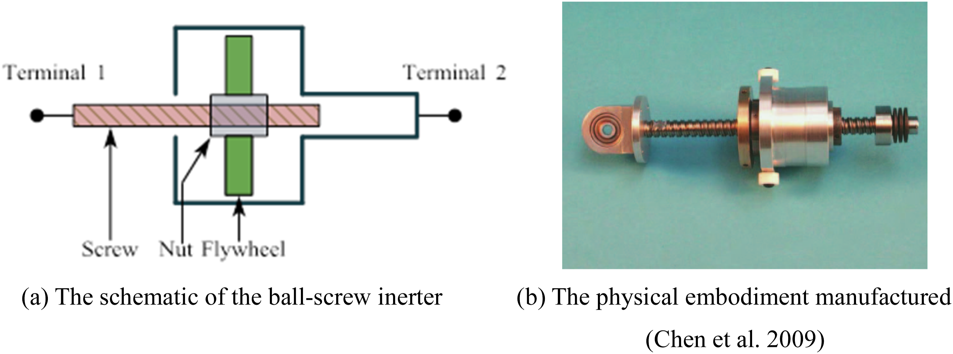
Among these, the ball-screw inerter are the most commonly used, primarily due to its inherently symmetrical design. Figure 1 shows the schematic and physical embodiments of the ball-screw inerter. The inertance of the ball-screw inerter can represented as the product of a transmission ratio and the flywheel’s moment of inertia, that is The ball-screw inerter. (a) The schematic of the ball-screw inerter. (b) The physical embodiment manufactured.
13

Some literature23,28 incorporated only an inerter into a vibration isolation system and termed it as an inertial mass damper (IMD), which was inappropriate since an inerter itself did not possess energy dissipation properties. It is typically not used alone but rather operates in conjunction with damper. To provide a clear explanation, a SDOF system that contains only an inerter, as shown in Figure 2, is analyzed in this section. The equation of motion for this system under harmonic force excitation is SDOF system with an inerter under harmonic force excitation.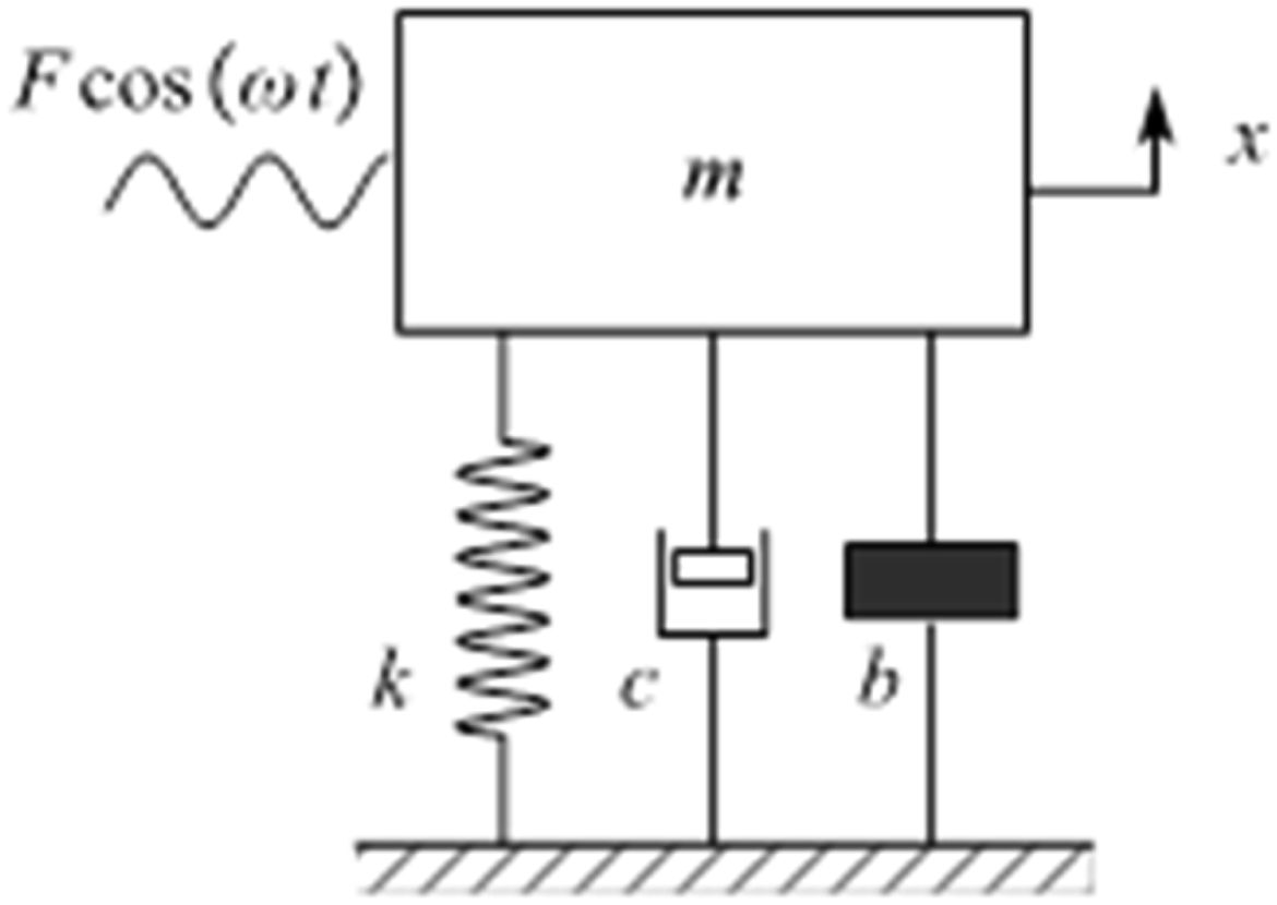

By defining
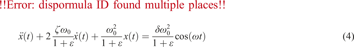
Equation (2) is transformed into the standard form for vibration analysis as
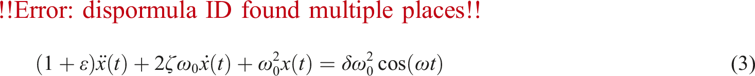
From equation (3), it can be observed that adding an inerter into the SDOF system results in the inertial term increasing to
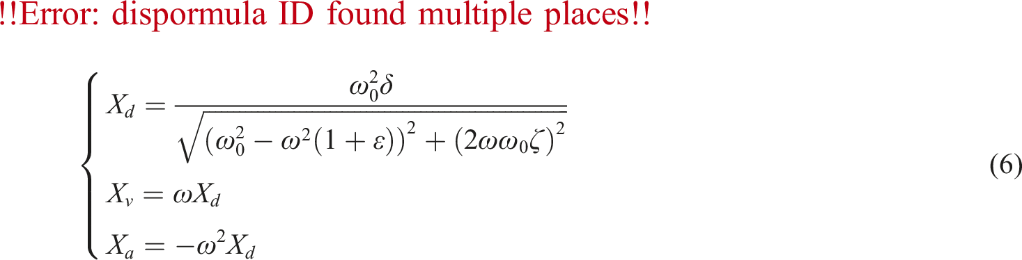
The solution has the form as

Substituting equation (5) into equation (4) leads to
Taking the partial derivative of equation (6) with respect to the excitation frequency ω and setting it equal to zero, one can obtain.
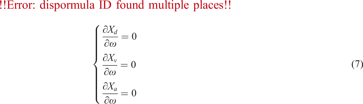
Solving equation (7) yields
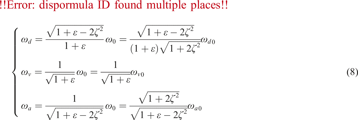
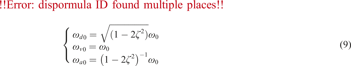
It is evident from equations (8) and (9) that, for small damping ratios, the resonant frequencies for displacement, velocity, and acceleration can be approximated as the natural frequency, as given by
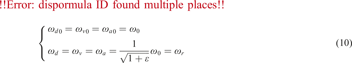
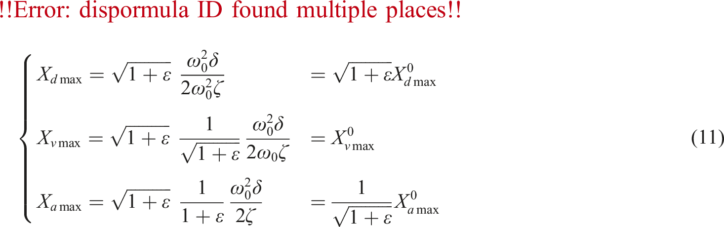
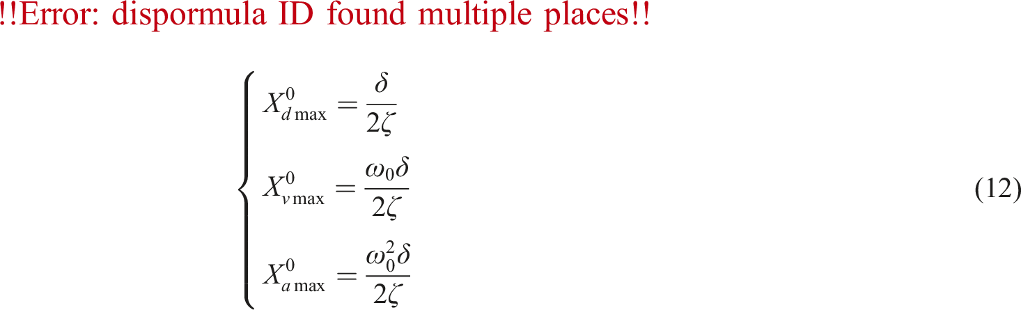
From equations (10)–(12), it can be observed that the addition of an inerter reduces the resonant frequency of the SDOF system by a factor of Amplification factors for the SDOF system with an inerter. (a) Displacement amplification factor. (b) Velocity amplification factor. (c) Acceleration amplification factor.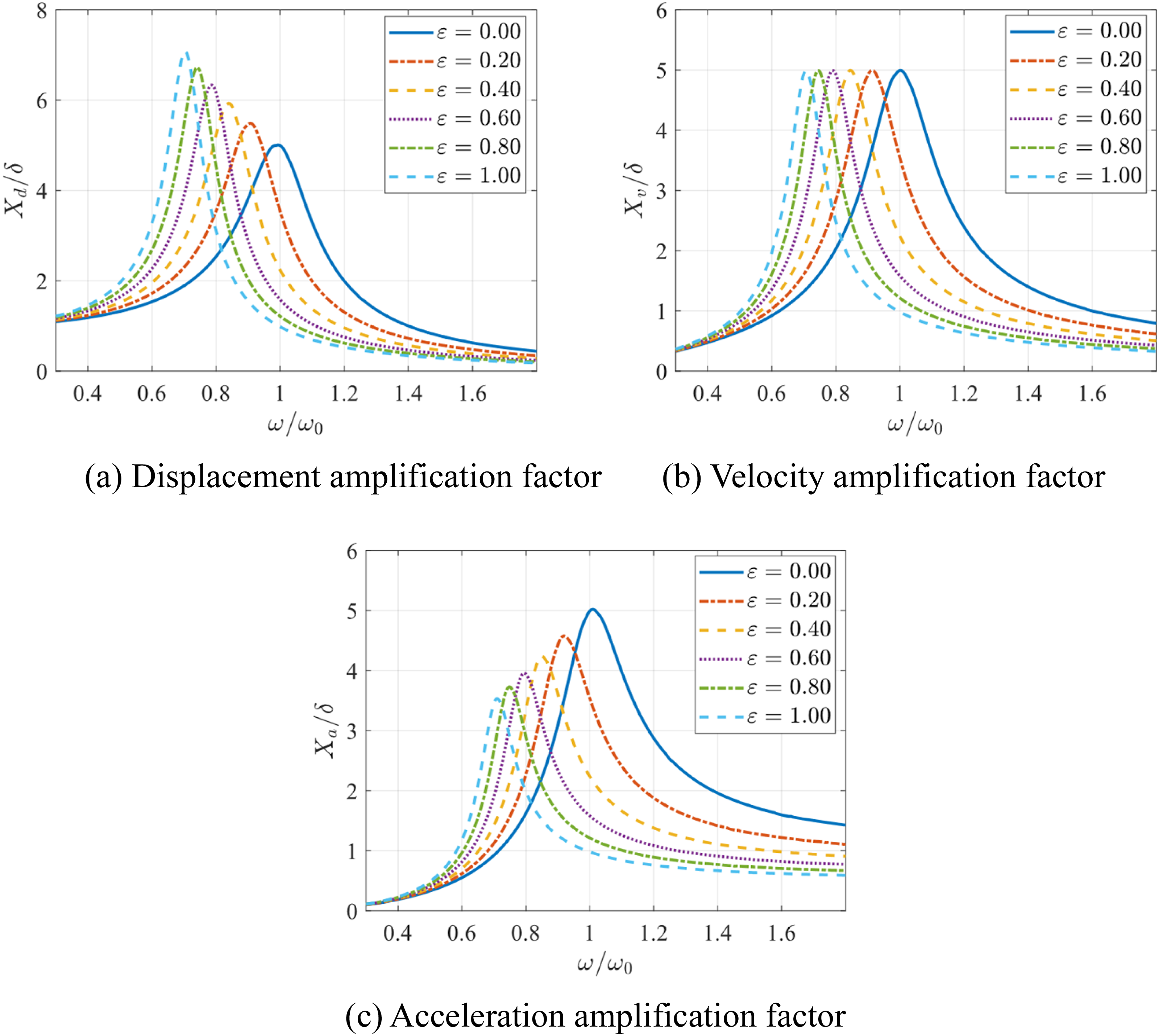
As observed from Figure 3, with the increase in the inertance ratio, the resonant frequency of the system shifts to the left, and the effectiveness of vibration control in the high-frequency range improves. This behavior is consistent with the earlier discussion, where an increase in inertance is analogous to the increase in mass. Additionally, the peak of the displacement increases, the peak of the velocity remains unchanged, and the peak of the acceleration significantly decreases. These results align with the conclusions derived from the previous equations.
SDOF system with an inerter damper (ID) under harmonic force
Based on the preceding analysis, it can be concluded that only addition of an inerter to the SDOF system without appropriate additional damping element will not reduce the responses of displacement and velocity. This is because the kinetic energy absorbed by the inerter cannot be dissipated in a timely manner in the absence or insufficiency of damping, leading to the partial or complete return of this energy to the primary system during vibration deceleration phase, thus failing to effectively suppress system vibrations. The schematic of the motion process is shown in Figure 4. Note that, unlike elastic elements, the energy input and output are in the same direction. To simultaneously improve the response of displacement, velocity, and acceleration, it is necessary to add appropriate damping elements to the inerter to form an ID, as shown in Figure 5. Working process of the inerter. (a) Vibration acceleration phase. (b) Vibration deceleration phase. SDOF system with an ID under harmonic force excitation.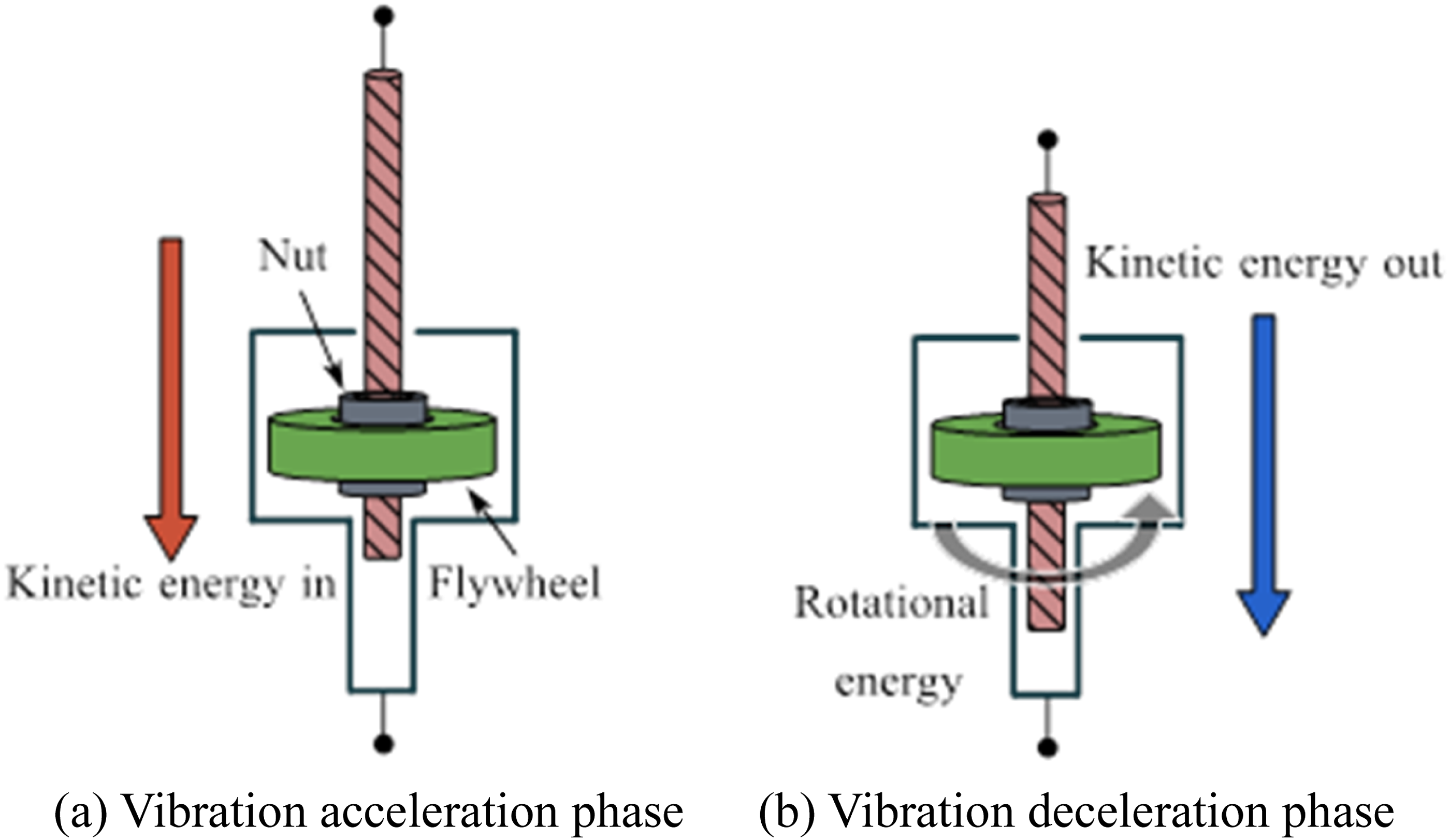
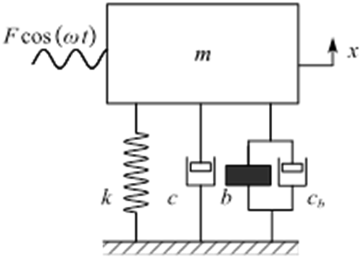
The equation of motion for this system shown in Figure 5 under harmonic force excitation is.

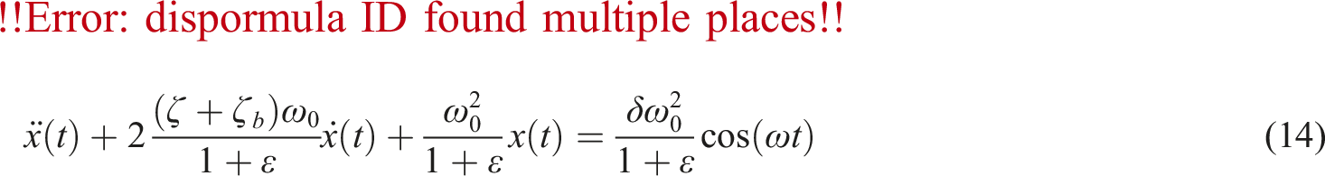
From equations (11), (13), and (14), it can be derived that when the ID satisfies the condition in equation (15), both the responses of acceleration, as well as those of displacement and velocity can be improved.

The solution of equation (14) can be expressed as
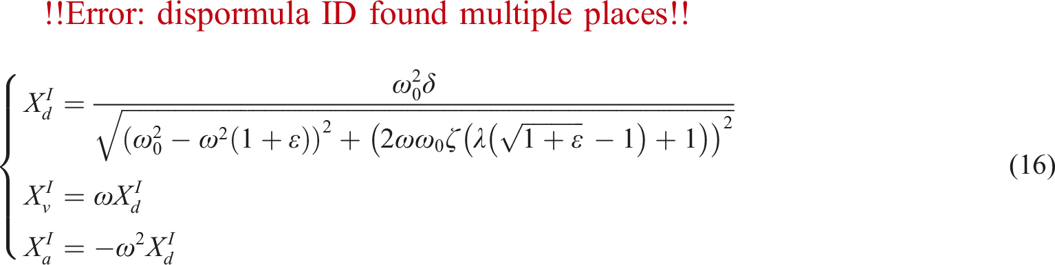
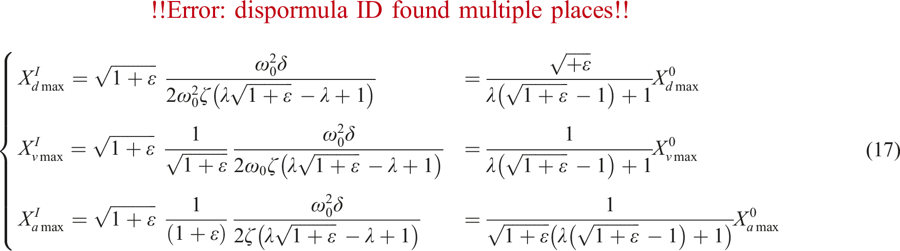
From equation (17), it can also be derived that when Amplification factors for the SDOF system with an ID. (a) Displacement amplification factor. (b) Velocity amplification factor. (c) Acceleration amplification factor.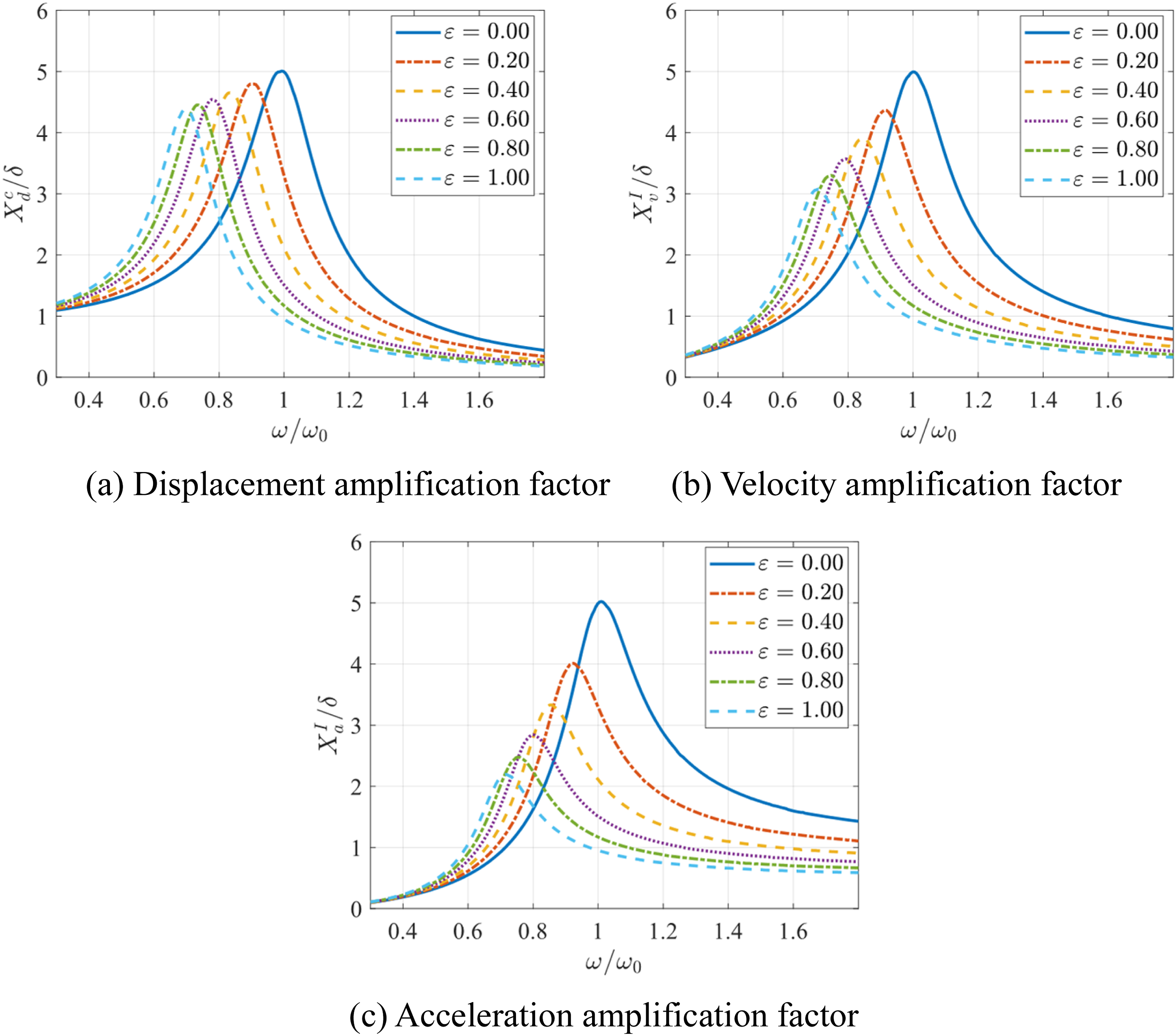
As shown in Figure 6, with the increase of the inertance ratio, the peaks of the amplification factors for displacement and velocity have decreased. Additionally, the peak for acceleration is also lower compared to the SDOF system with only an inerter. Therefore, by adding sufficient damping to the ID, the energy feedback issue of an inerter can be effectively counteracted. However, the damping force introduced by the added damping may have adverse effects on the system in certain aspects. According to vibration dynamics,
37
the force transmissibility is given by
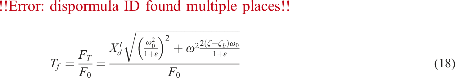
When Force transmissibility.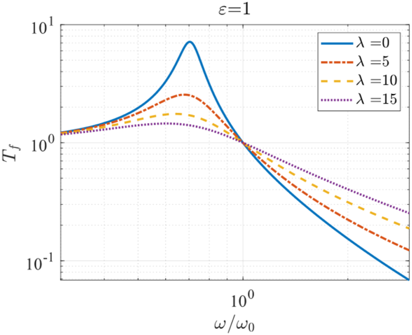
SDOF system with a CID under harmonic force
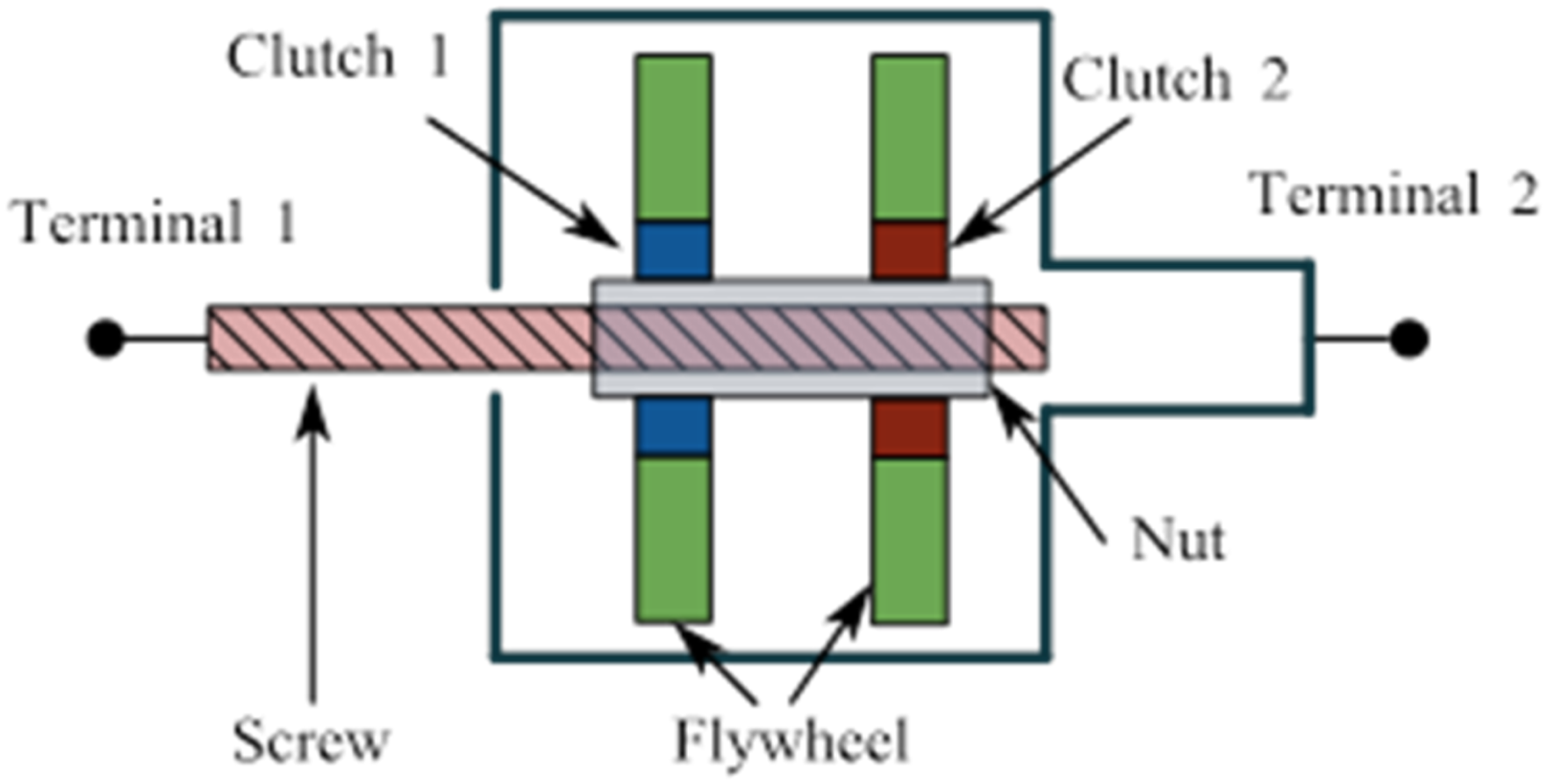
A CID typically consists of a one-way clutch and multiple flywheels. Common types of one-way clutches include ratchet clutches and sprag clutches, as shown in Figure 8. With this clutch, energy is irreversibly transferred away from the primary system to the flywheels. Common types of CID include rack-pinion and ball-screw types, with a schematic of the ball-screw type shown in Figure 9, and it should be noted that the assembled of the two clutches are opposite. The schematic of a ratchet clutch and a sprag clutch. (a) Ratchet clutch. (b) Sprag clutch. The schematic of the ball-screw CID.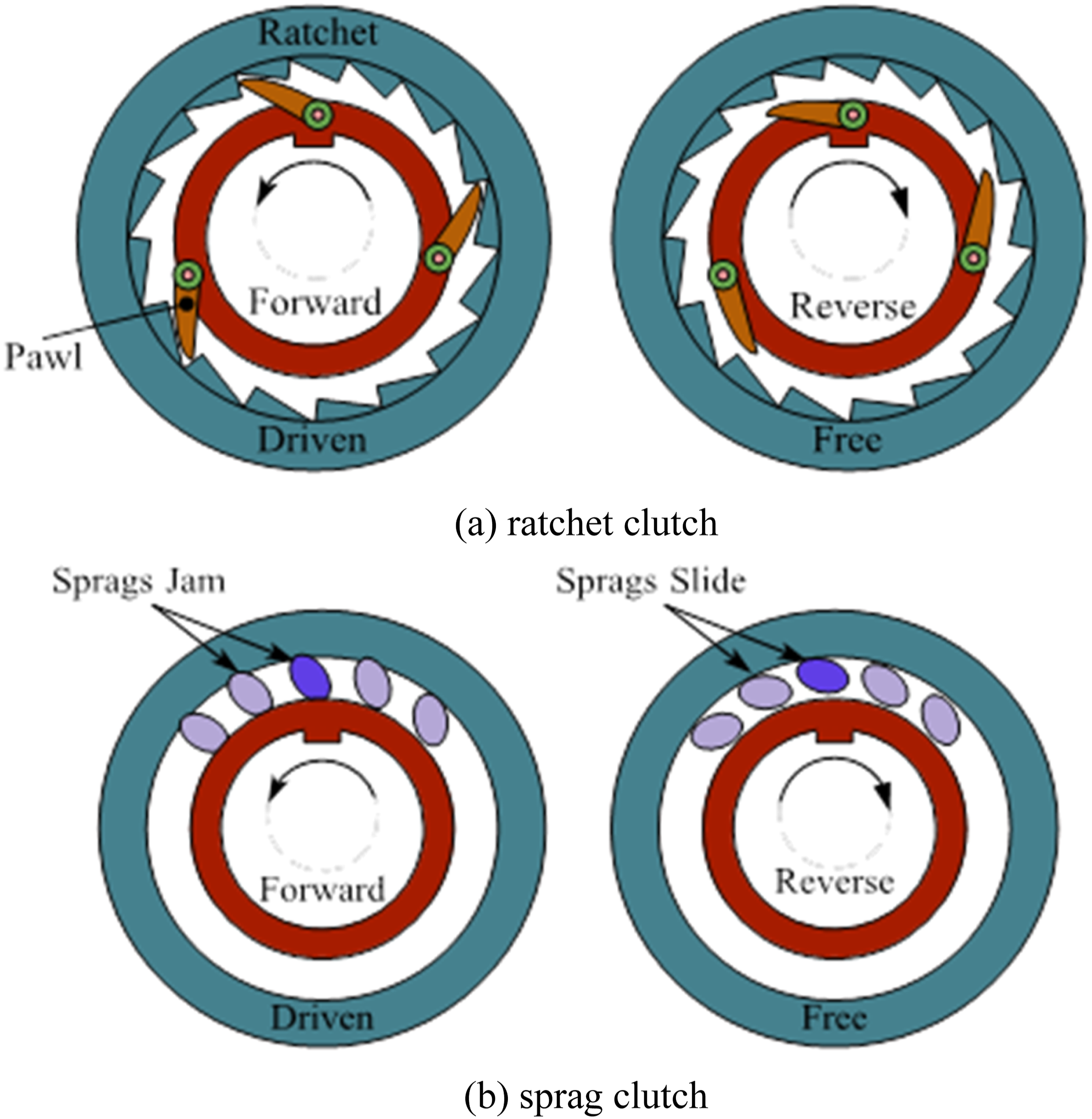
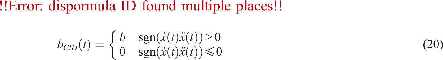
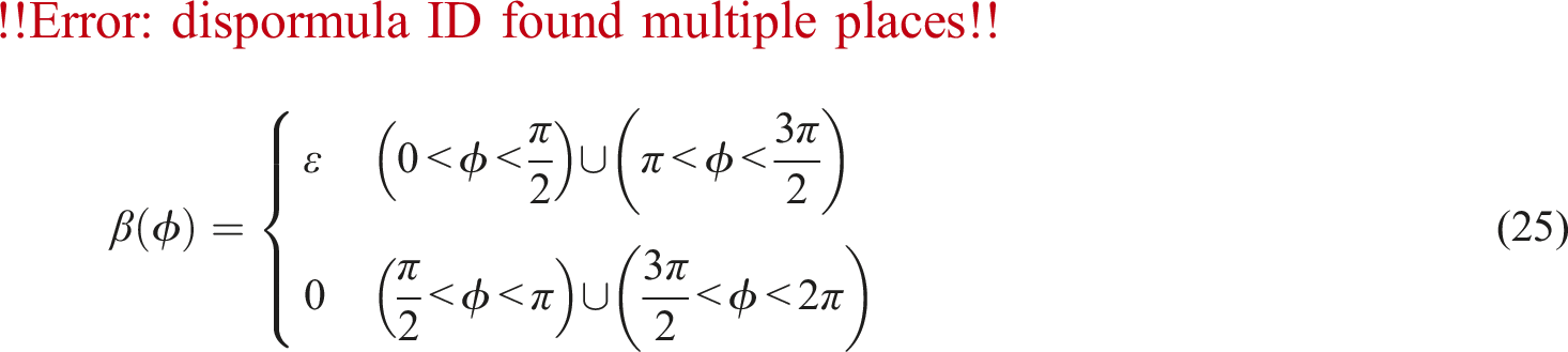
From the conceptual perspective of CID, the engagement or disengagement of the clutch is solely related to the speed and acceleration of the primary system, as shown in equation (20). The clutch engages when the directions of speed and acceleration are the same, and disengages if their directions are opposite. Therefore, the flywheel must have zero angular velocity before each engagement. Otherwise, the engagement will result in the return of rotational kinetic energy from the flywheel to the primary system if the angular velocity of the flywheel is not zero. Consequently, the rotational kinetic energy of the flywheel must be dissipated during disengagement. This dissipation can be achieved through harvesting systems or other energy-dissipating devices. Nevertheless, regardless of the dissipation method, the energy dissipation process must not affect the primary system. Due to this characteristic, the CID possesses energy-dissipating properties like damping, but without generating damping forces. In practice, a CID with a one-way clutch engages or disengages depending on the angular velocity of the flywheels, meaning that the angular velocity of the flywheel is not necessarily zero before each engagement, which leads to more complex scenarios. For ease of comparison and analysis, this section will only discuss the theoretical model of CID.
The model of SDOF system with a CID is shown in Figure 10, and its equation of motion under harmonic force is given by SDOF system with a CID under harmonic force excitation.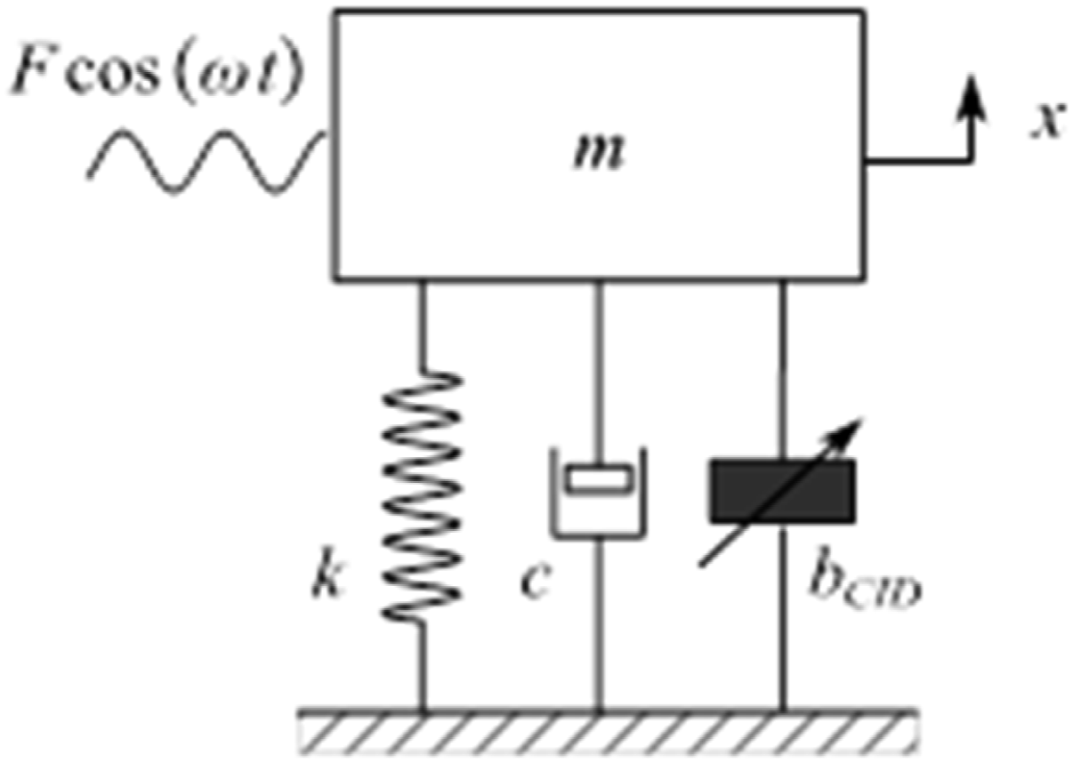

Introducing
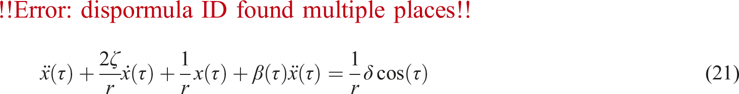
The averaging method is applied to obtain approximately analytical solution of equation (21). The solution has the form as

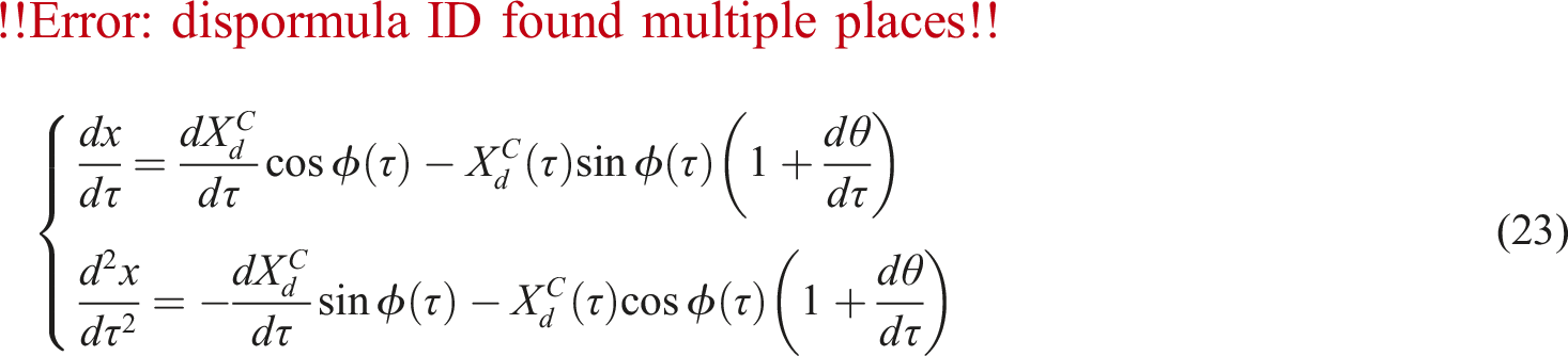
From equations (21)–(23), the following system of two differential equations can be derived
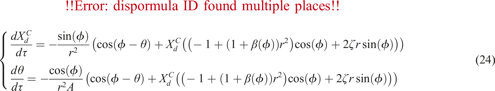
Next step should be to investigate the approximate forms for the derivatives of the amplitude and phase, by integrating the right-hand sides of equation (24) in one period, or
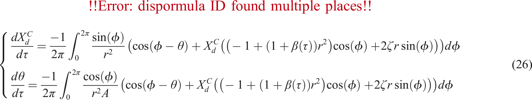
In this paper, only the steady-state response is considered. By letting
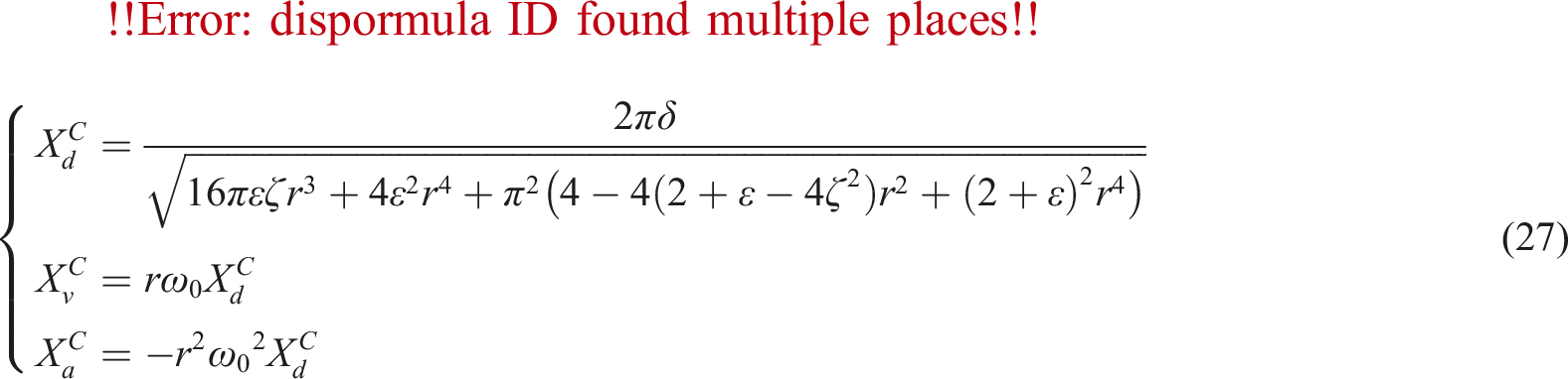
Dividing equation (27) by Amplification factors for the SDOF system with a CID. (a) Displacement amplification factor. (b) Velocity amplification factor. (c) Acceleration amplification factor.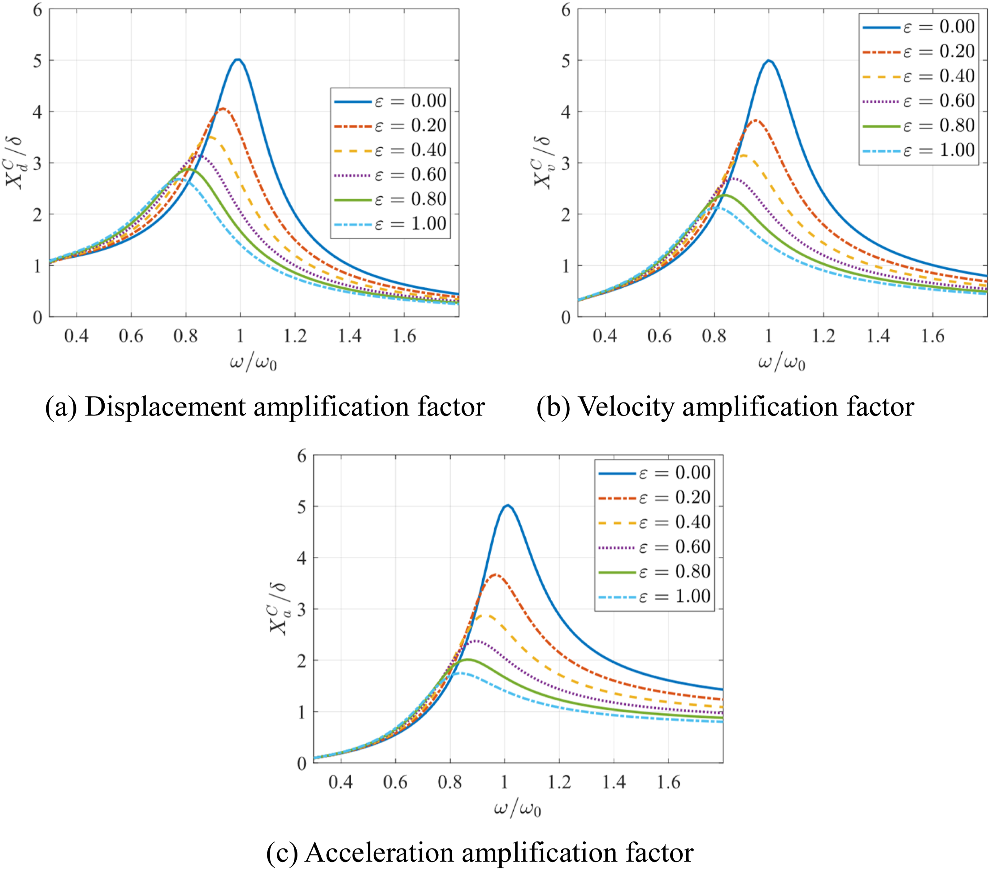
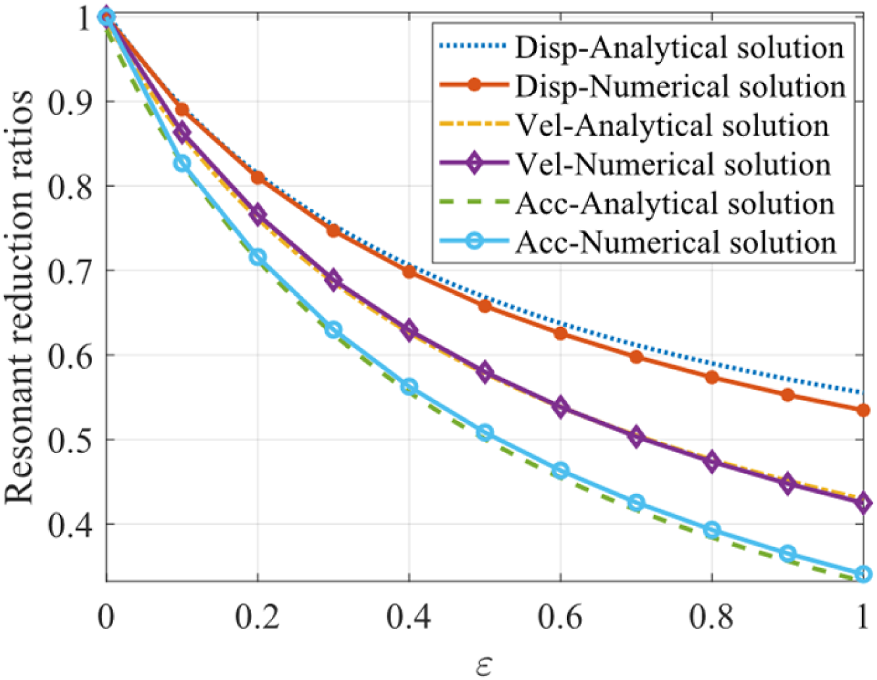
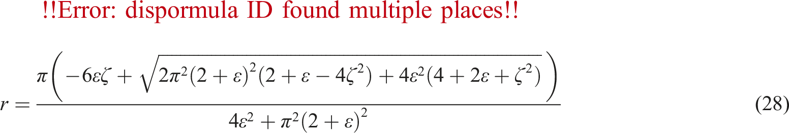
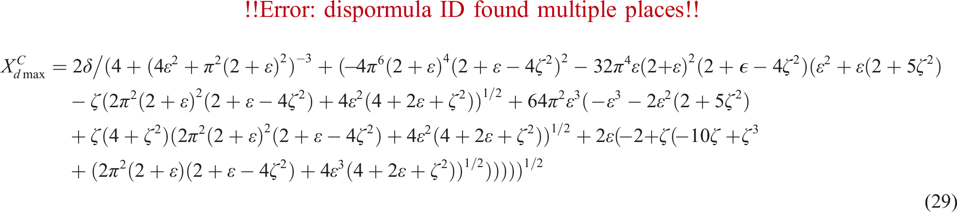
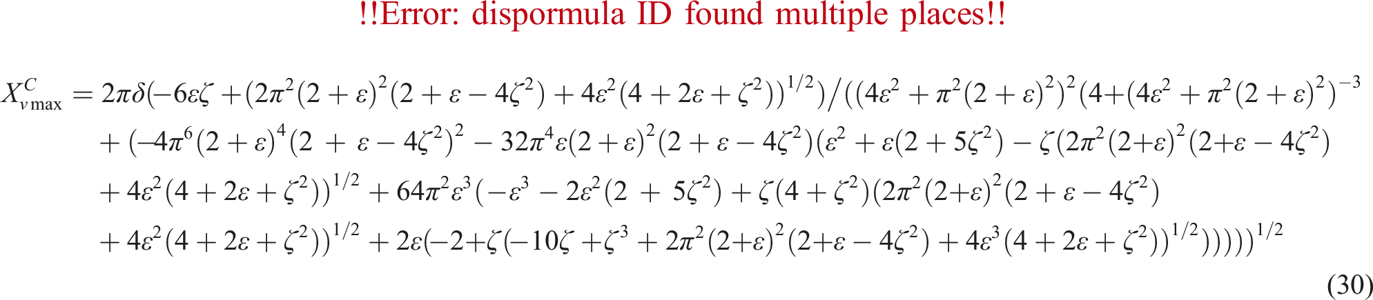
As shown in Figure 11, the resonant frequency of system is reduced with the increase in the inertance mass ratio, similar to systems with an ID. However, unlike this system, even without adding extra damping to the CID, its unique energy-dissipating properties lead to a reduction in the amplitudes of the displacement, velocity, and acceleration. This is consistent with the results discussed above. To further compare with ID, it is necessary to determine the specific values of the resonant frequency and the resonant amplitudes. From equation (27), by letting Resonant reduction ratios. Comparison of analytical and numerical solutions.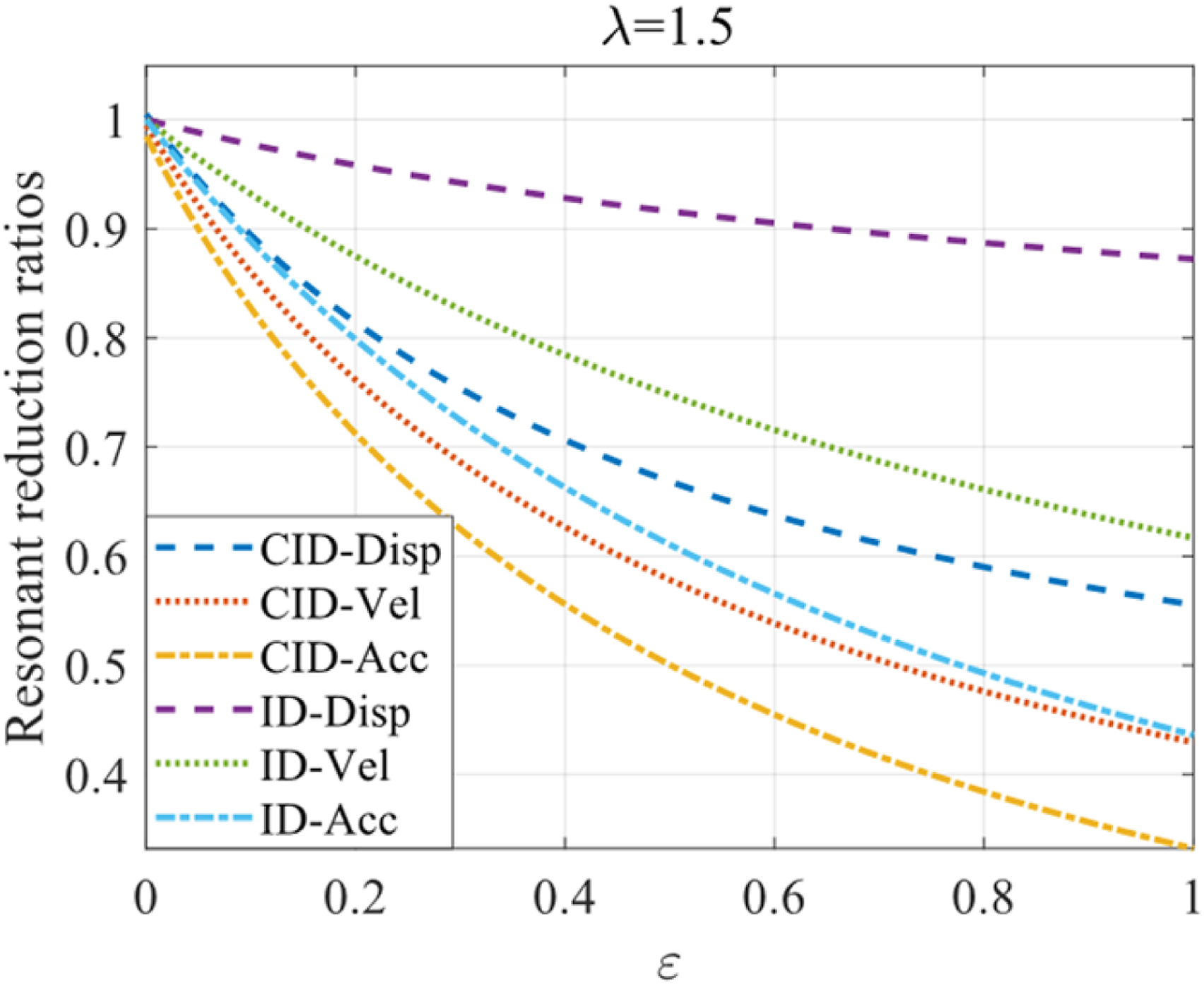
Compared to the averaging method, the ELM proposed by Wang et al.
27
will overestimate the resonant frequency. This is because the ELM approximates the force
From equation (32), it can be observed that its form is very similar to the ID. In other words, this method decomposes the CID into a parallel combination of an inerter with an inertance Resonant frequency ratios under harmonic force.

Responses under the harmonic base excitation
SDOF system with an inerter under harmonic base excitation
When the base or support of a SDOF system with an inerter undergoes harmonic motion, as shown in Figure 15, we can obtain the equations of motion SDOF system with an inerter under harmonic base excitation.

The displacement transmissibility
For different inertance mass ratio The displacement transmissibility, force transmissibility and relative displacement curves with an inerter. (a) Displacement transmissibility. (b) Force transmissibility. (c) Relative displacement.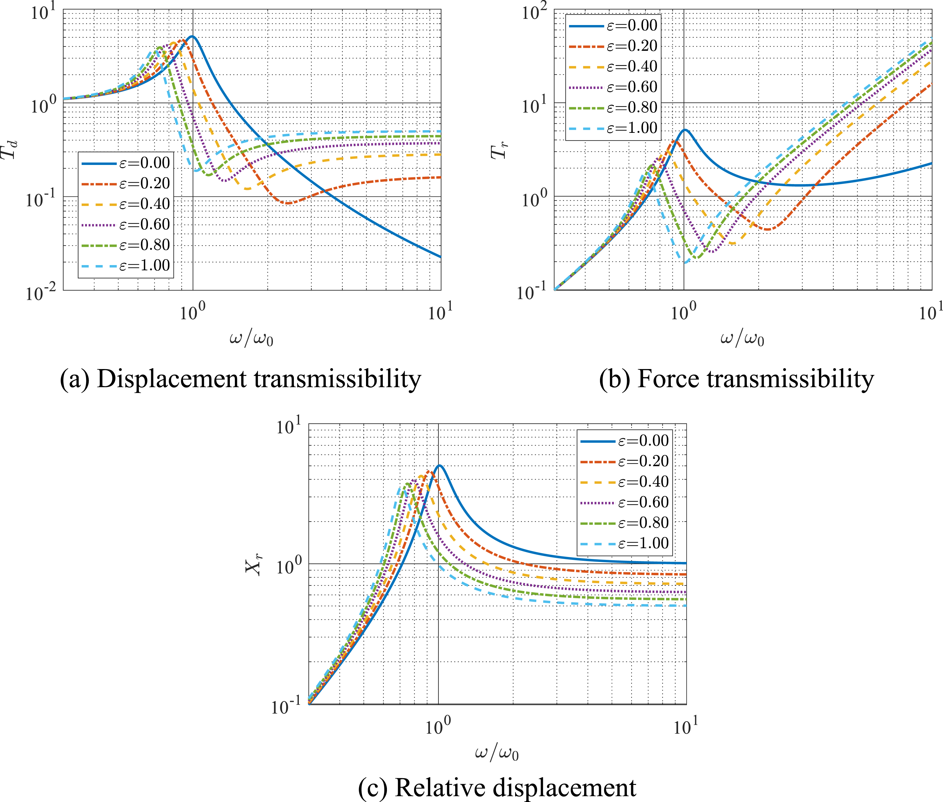
From Figure 16, it can be observed that as the inertance mass ratio
Therefore, to reveal the underlying reason for the reduction in resonant amplitude, the relative displacement

Let Energy interaction.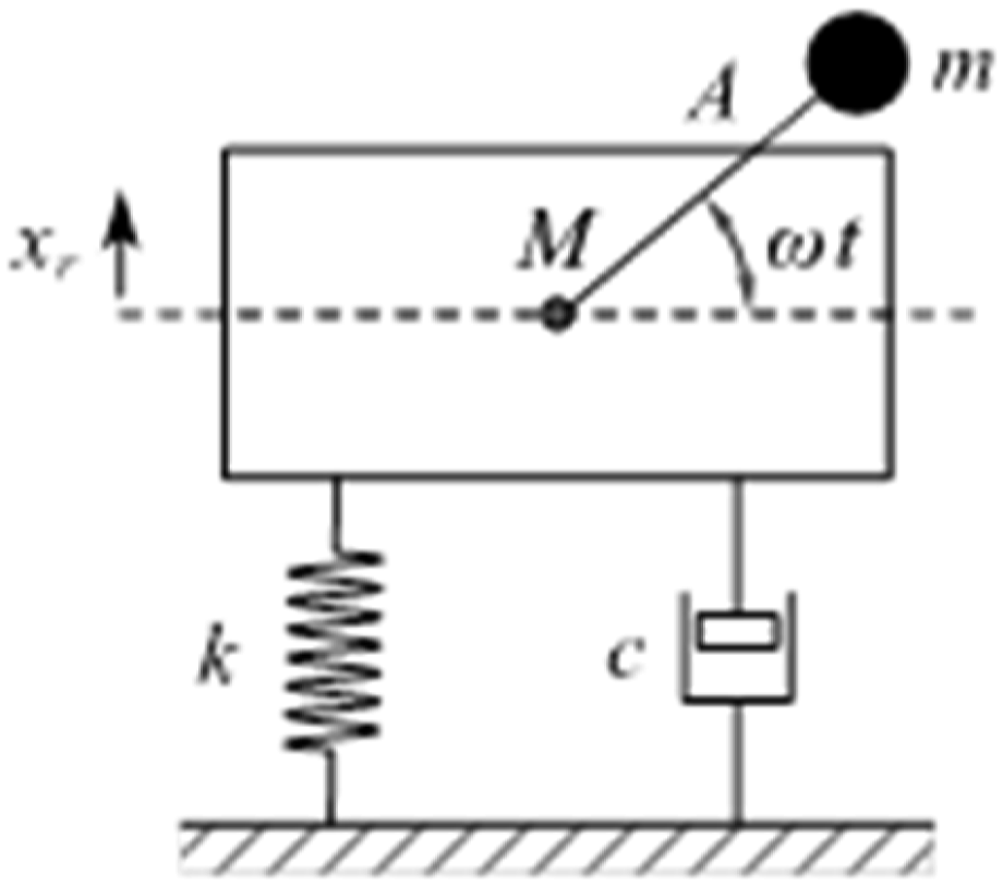

This indicates that the amplitude
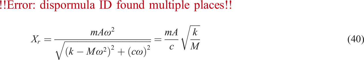
From equation (40), it can be observed that the resonant amplitude is inversely proportional to
SDOF system with a CID under harmonic base excitation
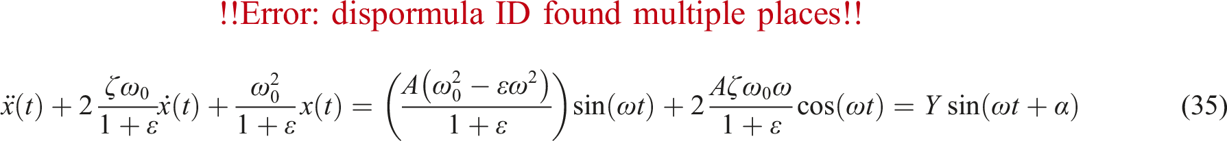
The model of SDOF system with a CID under harmonic base excitation is shown in Figure 18, and its equation of motion is given by SDOF system with a CID under harmonic base excitation.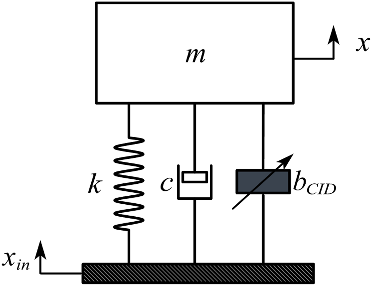

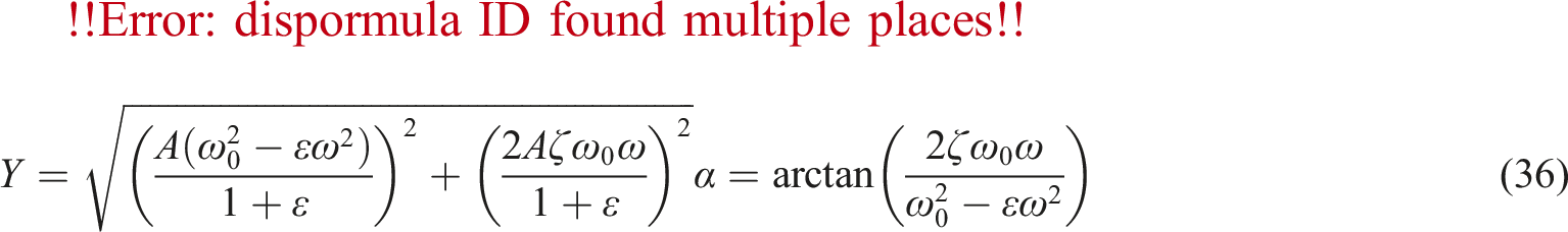
After normalization, we obtain
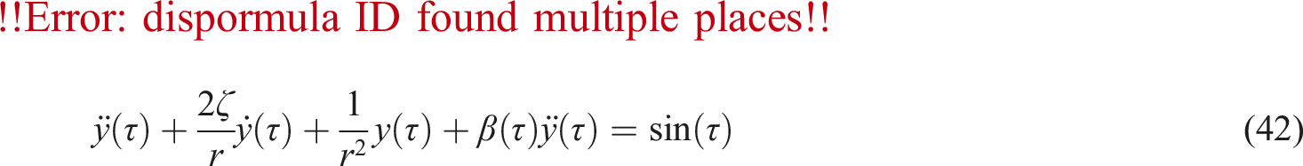
The averaging method is applied to obtain approximately analytical solution of equation (42). The solution has the form as

By differentiating equation (43) with respect to
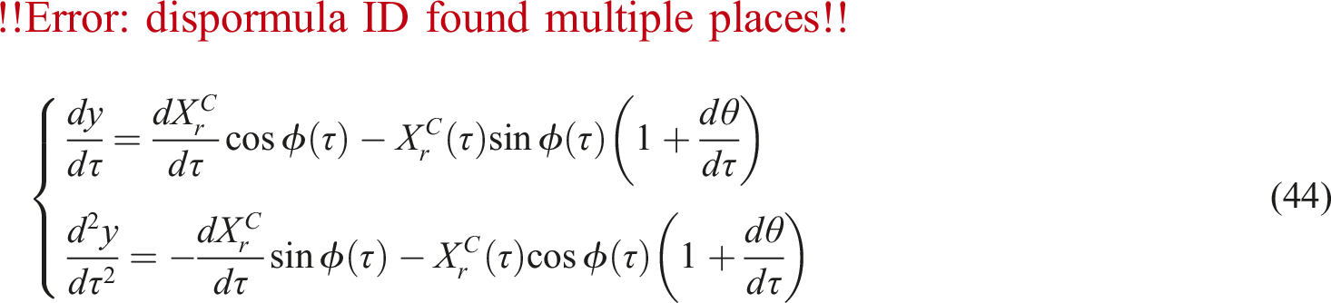
The subsequent solution process is consistent with that under harmonic force excitation, so that the relative displacement
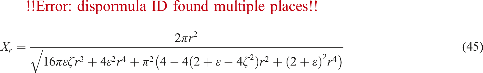
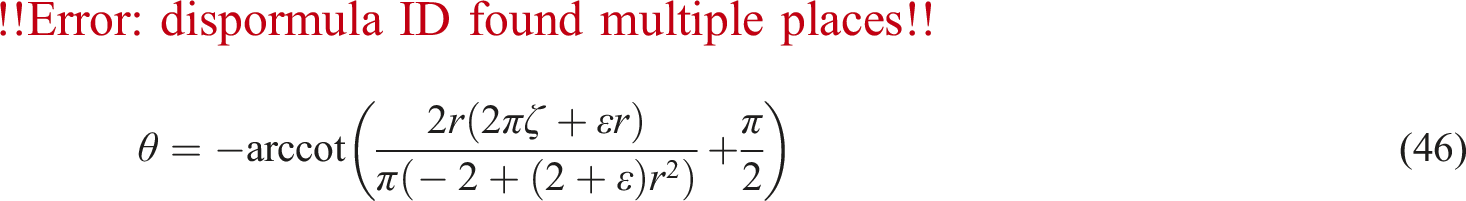
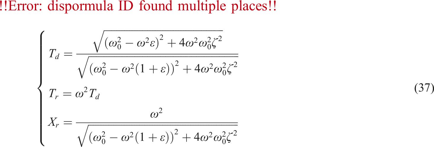
From equations (45) and (46), the displacement transmissibility
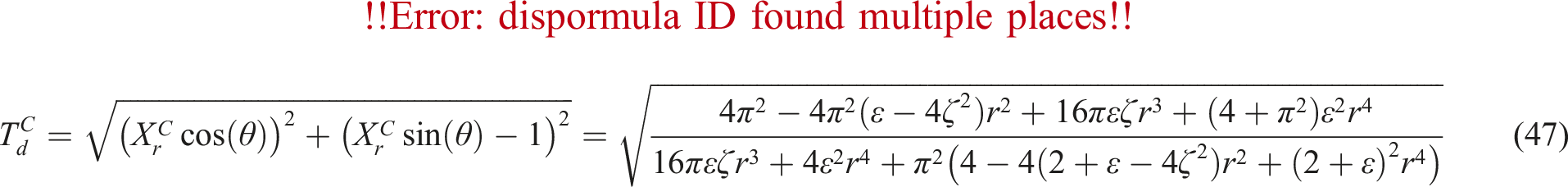
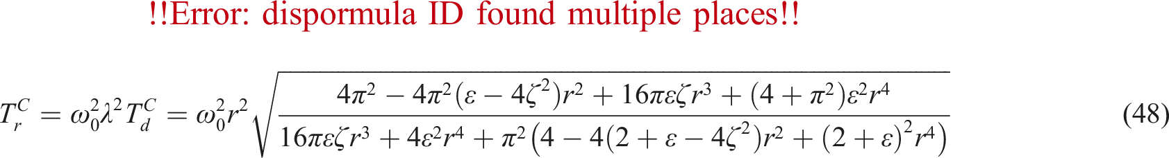
For different inertance mass ratio The displacement transmissibility, force transmissibility and relative displacement curves with a CID. (a) Displacement transmissibility. (b) Force transmissibility. (c) Relative displacement.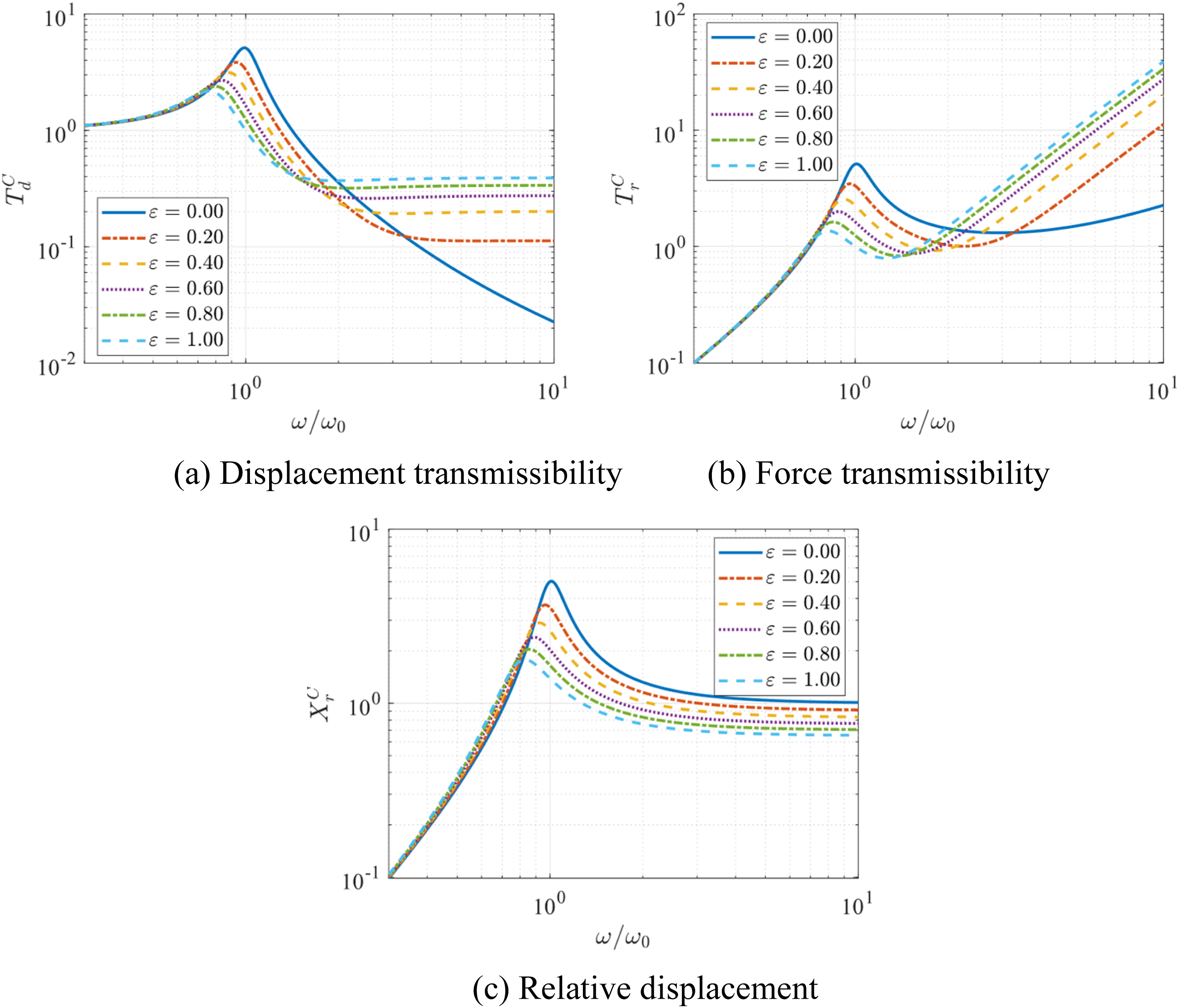
As shown in the figure, there is little difference compared to the SDOF system with an inerter. Both systems exhibit effective vibration suppression in the resonant region, while the force transmissibility increases sharply in the high frequencies range. To qualitatively assess the vibration reduction effect in the resonant region, the resonant frequencies are substituted into equations (37), (45), (47), and (48). The results are normalized to obtain the resonant reduction ratios, as illustrated in Figure 20. Resonant reduction ratios under harmonic base excitation.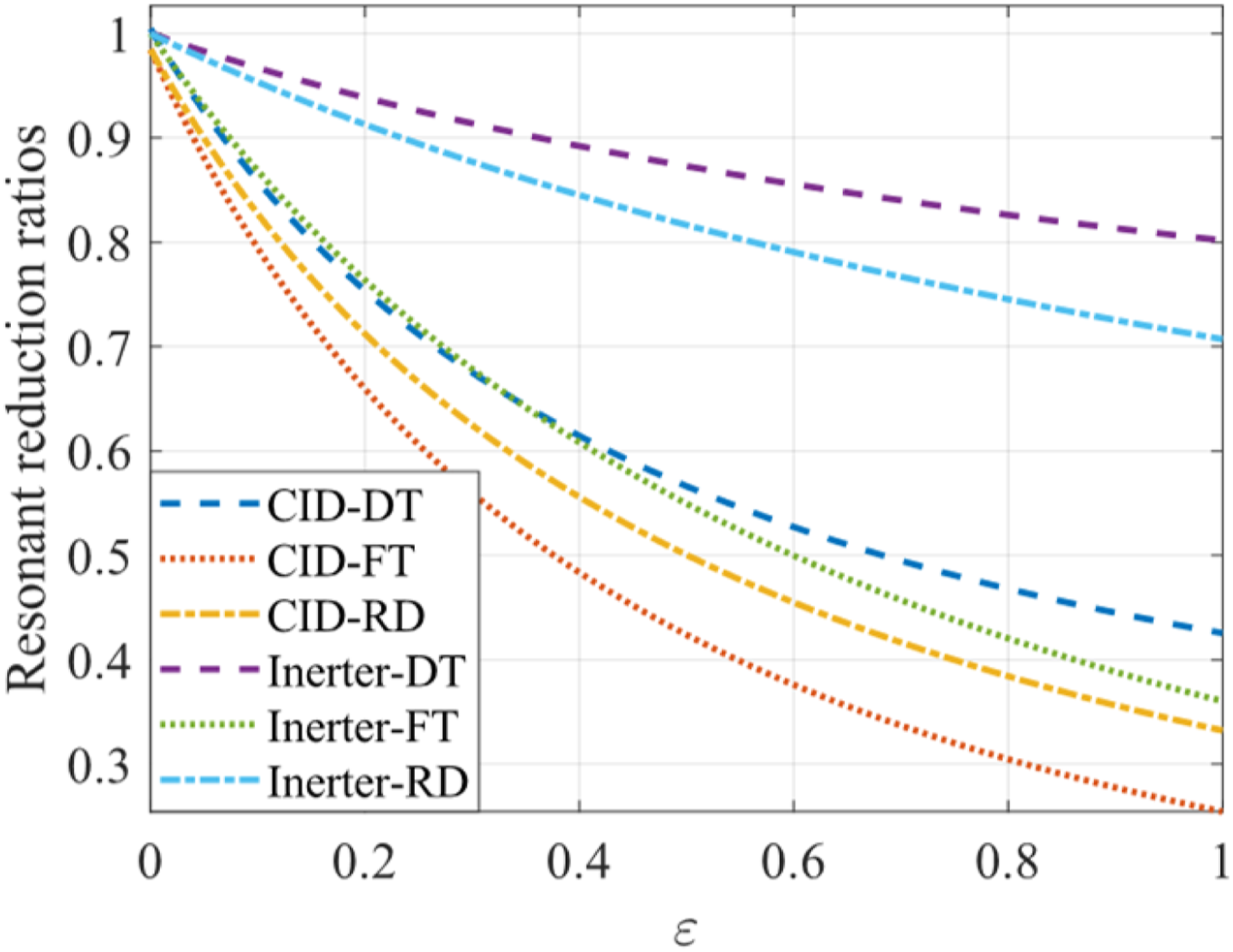
In the figure, DT, FT, and RD represent displacement transmissibility, force transmissibility, and relative displacement, respectively. Under base excitation, the inerter can reduce the amplitude of the excitation force at resonance, thereby decreasing the resonant amplitude. However, the figure illustrates that the vibration suppression performance of the SDOF system with a CID is significantly superior to that with an inerter in the resonant region. This is because the CID not only reduces the excitation amplitude at resonance but also possesses unique energy-dissipating characteristics, resulting in an effect similar to enhanced damping.
Conclusion
This study investigates the dynamic response of SDOF systems equipped with either an inerter or a CID under harmonic force and base excitation. The study highlights that, under harmonic force excitation, an inerter paired with a damping element prevents energy from being returned to the primary system by dissipating the energy transferred to the flywheels. This mechanism improves the dynamic response of the system. However, the addition of the damping element introduces extra damping forces, which worsen force transmissibility in certain frequency ranges. In comparison, the clutch mechanism of the CID effectively cuts off the path of energy return, providing a damping-like effect without introducing additional damping forces. To address the nonlinear nature of the CID, the averaging method is employed, and its results demonstrate higher accuracy compared to the ELM, particularly in avoiding overestimation of resonant frequencies.
Under harmonic base excitation, increasing inertance reduces both the damping ratio and excitation amplitude, ultimately lowering the resonance amplitude as excitation amplitude reduction dominates. However, due to the inherent low-pass filtering property, the vibration suppression effectiveness of both the inerter and CID declines at high frequencies. Notably, the CID surpasses the inerter in vibration suppression within the resonant region, making it a more effective solution for practical applications. The main conclusions are summarized as follows. 1. Under harmonic force excitation, due to the force feedback issue of the inerter, adding only an inerter to the SDOF system without an appropriate additional damping element will not improve the displacement and velocity responses. 2. Under harmonic force excitation, in a SDOF system equipped with an ID, if the damping coefficient 3. The averaging method is used to solve the SDOF system with a CID under harmonic excitations, and the obtained analytical solutions closely match the numerical solutions. Although the error gradually increases with the inertance mass ratio, it remains within a reasonable range. Compared to the ELM, the averaging method offers higher accuracy and does not overestimate the resonant frequency. 4. Under harmonic force excitation, the CID effectively reduces the resonant amplitudes of displacement, velocity, and acceleration. Although the ID also attenuates the resonant amplitudes when 5. Under harmonic base excitation, the inerter not only reduces the resonant frequency and damping ratio but also decreases the excitation amplitude. While a lower damping ratio tends to increase the sensitivity of the system response, theoretically leading to a higher resonant amplitude, this tendency is counterbalanced by the reduction in excitation amplitude. Consequently, increasing the inertance mass ratio has a more pronounced effect on reducing the excitation, ultimately leading to a decrease in the resonant amplitudes of the system. However, at high excitation frequencies, the addition of the inerter negatively impacts the force and displacement transmissibility. In particular, the force transmissibility deteriorates rapidly as the excitation frequency increases. 6. Under harmonic base excitation, the performance of the CID is largely similar to that of the inerter, with both exhibiting deteriorated force transmissibility in the high-frequency region. However, owing to its distinctive energy-dissipating properties, the CID demonstrates superior vibration control compared to the inerter within the resonant region.
Future research will focus on the dynamic characteristics of the inerter and the CID in MDOF systems, particularly under base excitation. It will specifically investigate whether their vibration suppression performance and behavior are similar to those in SDOF systems. Additionally, the research will delve into their effects on system stability, resonance attenuation, and energy dissipation.
Footnotes
Declaration of conflicting interests
The author(s) declared no potential conflicts of interest with respect to the research, authorship, and/or publication of this article.
Funding
The author(s) disclosed receipt of the following financial support for the research, authorship, and/or publication of this article: The authors are grateful for the financial support from the National Natural Science Foundation of China (grant numbers 12272242).