
Abstract
Most APFs use improved designs of active power filters of half-bridge and full-bridge circuits, their advantages and disadvantages are compared. International journals often use this filter circuit for small circuit boards. For large power systems, nonlinear loads still need to overcome harmonic pollution and magnetic pollution. Its disadvantage is that it will reduce the power of the system and requires power compensation. For nonlinear load harmonic filtering, RLC high-pass filter is not the best filtering method. Due to high-power rail high-voltage systems (22 KV–161 KV), the industry has not yet applied APF to remove harmonics. Previous research on nonlinear load harmonic filters for high-voltage systems was only 6.9 KV. Later, with the development of industry and the increase in electricity consumption, the high-voltage system increased to 22 KV–161 KV. Experimental data on high-voltage power systems are difficult to obtain. This study verified the feasibility of this method through simulation. Therefore, this study proposes to use a combination of two single-phase high-pass filters form a three-phase APF to filter nonlinear load harmonics in the track’s large power system and effectively increase the capacity of the large power load. APF filters harmonics through three phases to prevent train signal abnormalities and extend the service life of trains. Since the centralized power supply system must be used in conjunction with other loads, harmonic pollution will occur. Electric vehicles accept this kind of pollution source, which is detrimental to on-board equipment and on-board signals. In power electronics theory, the spirit of this article is to use APF to filter out harmonics of the power system through three-phase technology in the range of 22 KV–161 KV. This has not yet been done in the industry. I put forward this theory, which is also the meaning of this job.
Introduction
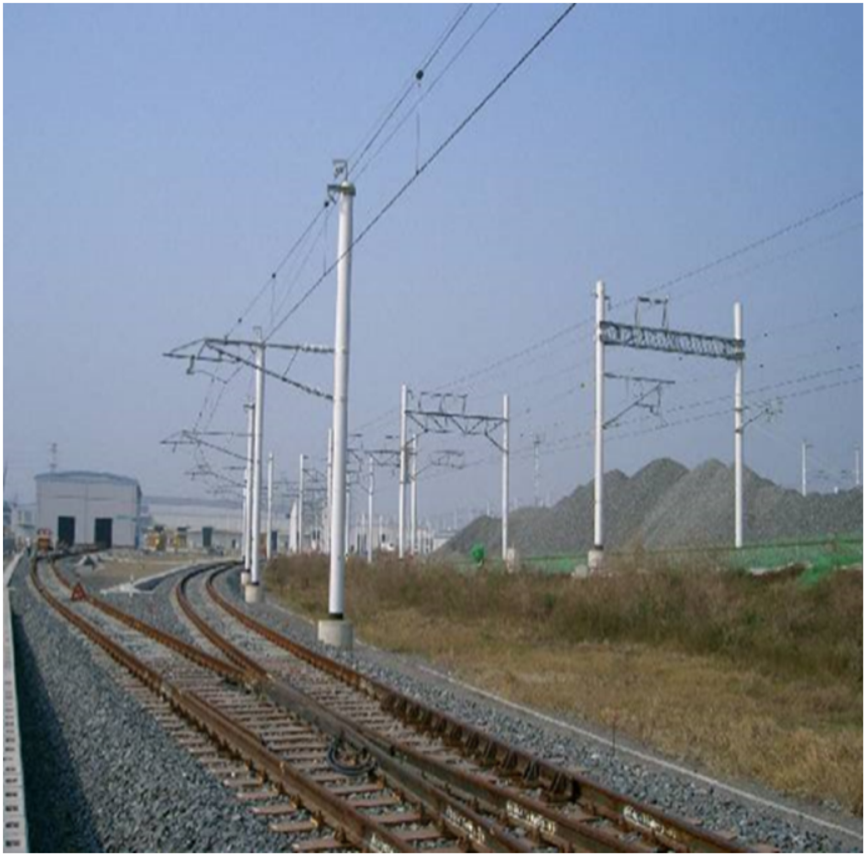
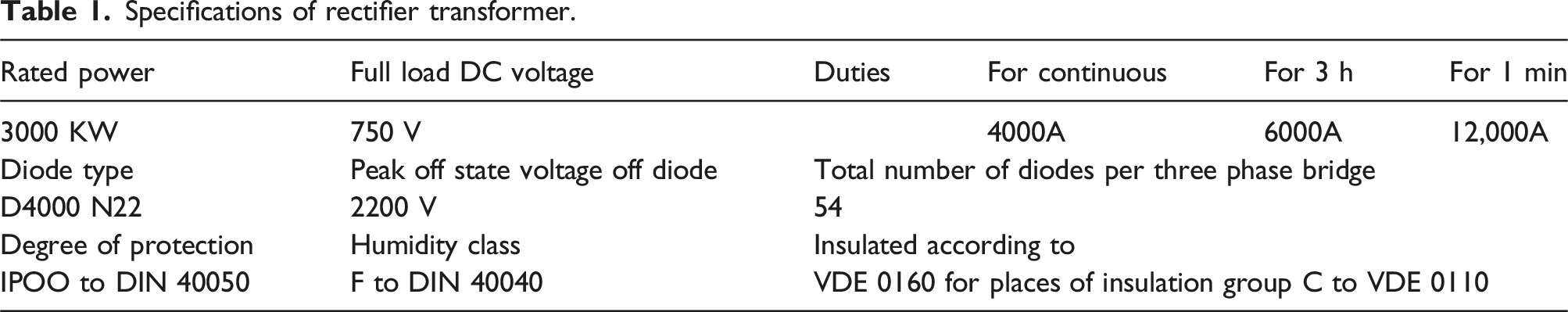
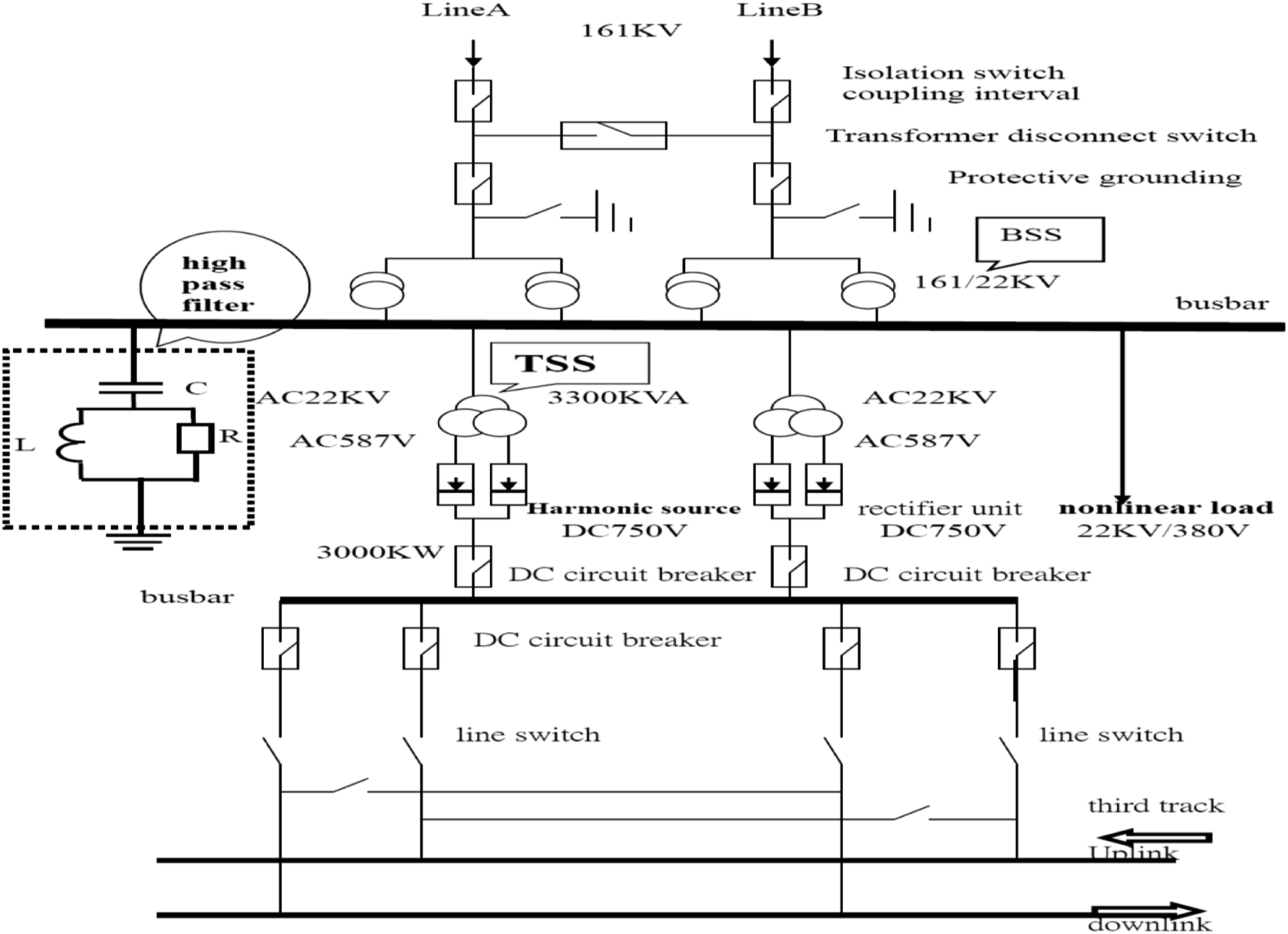
The power supply of the MRT system (as shown in Figure 1) is taken from the 161 KV power company and passes through three substations, the main substation (BSS), the traction substation (TSS), the station substation (SSS), the transfer unit DC750 V, and the MRT station AC380 V. The 22 KV from BSS (161/22 KV) to TSS (22 KV/587V) (as shown in Figure 2) is rectified and outputs DC750 V (as shown in Table 1), which is connected to the third rail through a line switch. At present, DC equipment uses high-voltage diode rectification. The AC transformer is placed in the main transformer BSS (161/22 KV) and the station substation SSS (22 KV/380 V). In order to prevent failures caused by harmonic current and insufficient effective power, a damping unit is installed on the primary side of TSS (secondary side of BSS) to filter out harmonics, improve reactive power consumption, and increase active power output. In order to prevent lightning strikes, a surge absorption circuit is installed to absorb surge current and reduce diode burnout. In order to protect the relay from damage to the transformer caused by fault current when used in short circuit, this study uses an active power filter (APF) to improve the harmonics of the MRT power system without reducing the power. The power system does not require power compensation, effectively extending the service life of MRT trains. MRT vehicle. 22 KV power line. Specifications of rectifier transformer.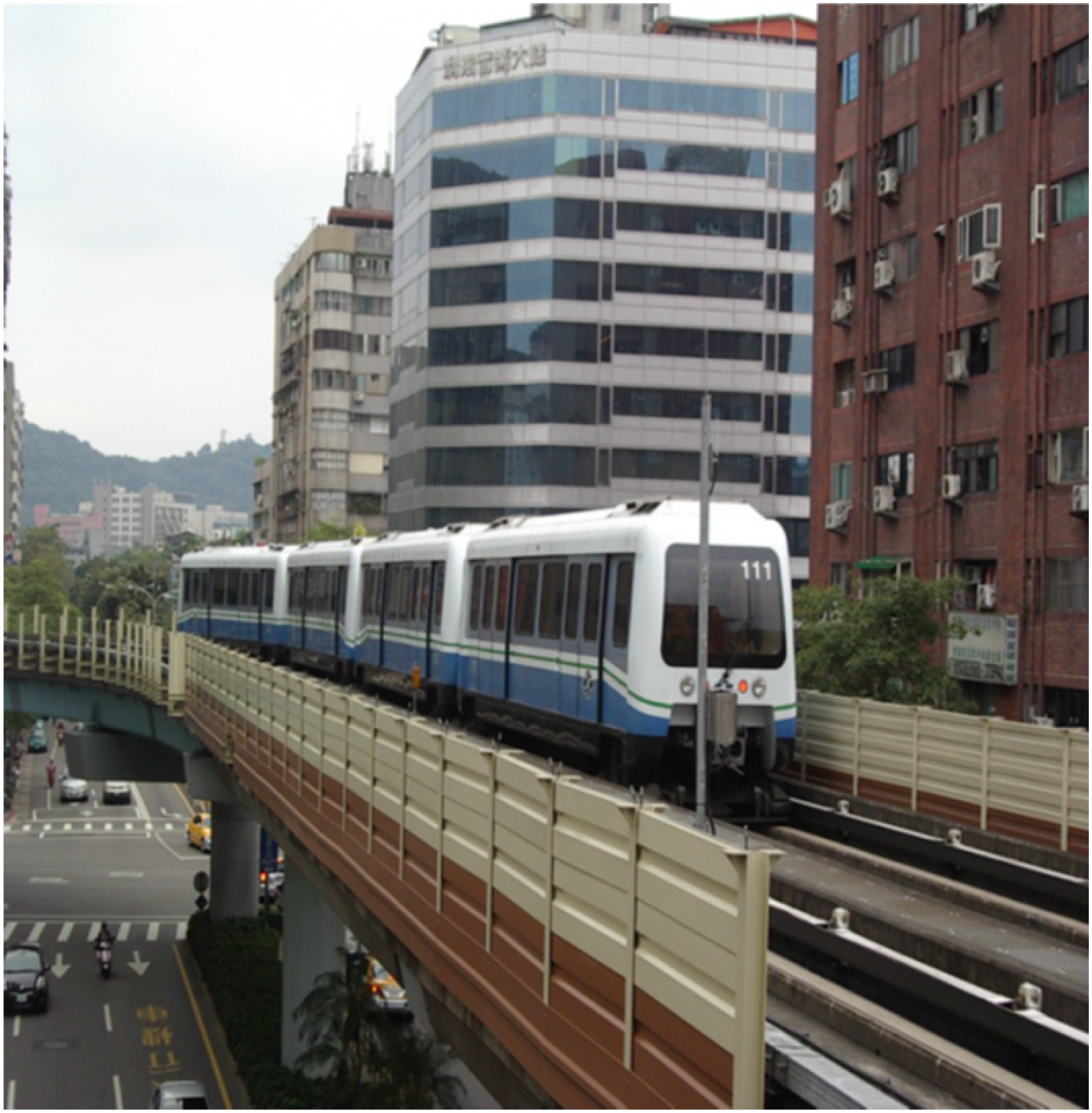
The high-power system in this study is derived from the following two circuit structures 1 to simulate the output waveform of a three-phase induction motor and compare its advantages and disadvantages in order to supply it to MRT trains in the future.
In addition to the fundamental frequency in the power supply of the power system, due to the use of AC power supply, there are also many frequency components that are multiples of the fundamental frequency, referred to as harmonics. Harmonic distortion is caused by nonlinear characteristics of voltage-current in power systems. A nonlinear component is a circuit in which the voltage across the component is not linearly proportional to the current flowing through the component. In general, frequency-dependent components do not necessarily have anything to do with nonlinearity, which means that the components are frequency-dependent and do not cause waveform distortion. The largest sources of harmonics in power systems are nonlinear components, such as motor loads or special switchgear. 2
This study focuses on the improvement of the harmonic slope when the BSS’s 22 KV/AC voltage enters the rectifier, which is 750 V/DC direct current. It is converted into alternating current through the converter and supplied to the vehicle-mounted three-phase induction motor. Apply the APF principle to improve harmonics, simulate the principle, and observe the voltage waveform to verify that APF has indeed achieved the effect of improving harmonics, reducing signal error signals, and promoting the normal operation of electric vehicles.
At present, most large power systems come from centralized AC power. Because the centralized power system must be used with other loads, it will produce harmonic pollution. The E-Vehicle accepts this pollution source, which is detrimental to on-board equipment and on-board signals. This study hopes to convert the power input. It is a smooth sine three-phase waveform (Figure 23) instead of the acupuncture waveform in Figure 15 and the weakened waveform in Figure 19, which makes the operation and operation of the electric vehicle more energy-saving and has a longer life, which is not a simple matter for large power systems.
Pinheiro and Barbi and Professor Ruan Xinbo started APF research on nonlinear load harmonic filtering, so that researchers no longer use RLC analog circuits to filter harmonics. RLC analog circuits will weaken the power. However, this is a single-phase circuit and can only be used for circuit boards in weak currents, Professor Hirofumi Akagi’s research has brought APF into three-phase circuit systems, and has also applied APF to high-power transformerless 6.9 KV motor harmonic filtering, effectively solving motor harmonics and electromagnetic induction effects; however, there were no 22 KV and 161 KV power systems in Professor Hirofumi Akagi’s era. According to Professor Hirofumi Akagi’s research, it was limited to the 6.9 KV range, and his research used IGBT analog component circuits, which would cause power be weaken and power compensation was done.
This research uses semiconductor materials as APF components to reduce frequency resonance, weaken power phenomena, and achieve the effect of filtering harmonics. The high-pass filter itself has the effect of filtering harmonics. Two single-phase high-pass filters are connected in parallel and used semiconductor materials will effectively reduce the volume of the APF circuit and filter out large power harmonic sources. This is the reason and significance of this study.
Harmonic measurement between two MRT stations
The background of this study is that electromechanical integration testing is required when the E-linked vehicle is put into service. Since the harmonics of the power system are not filtered out, the signaling system often malfunctions and the vehicle speed slows down due to insufficient power of the E-linked vehicle, which causes me to Interest in pursuing this research.
Measurement data and formula calculation
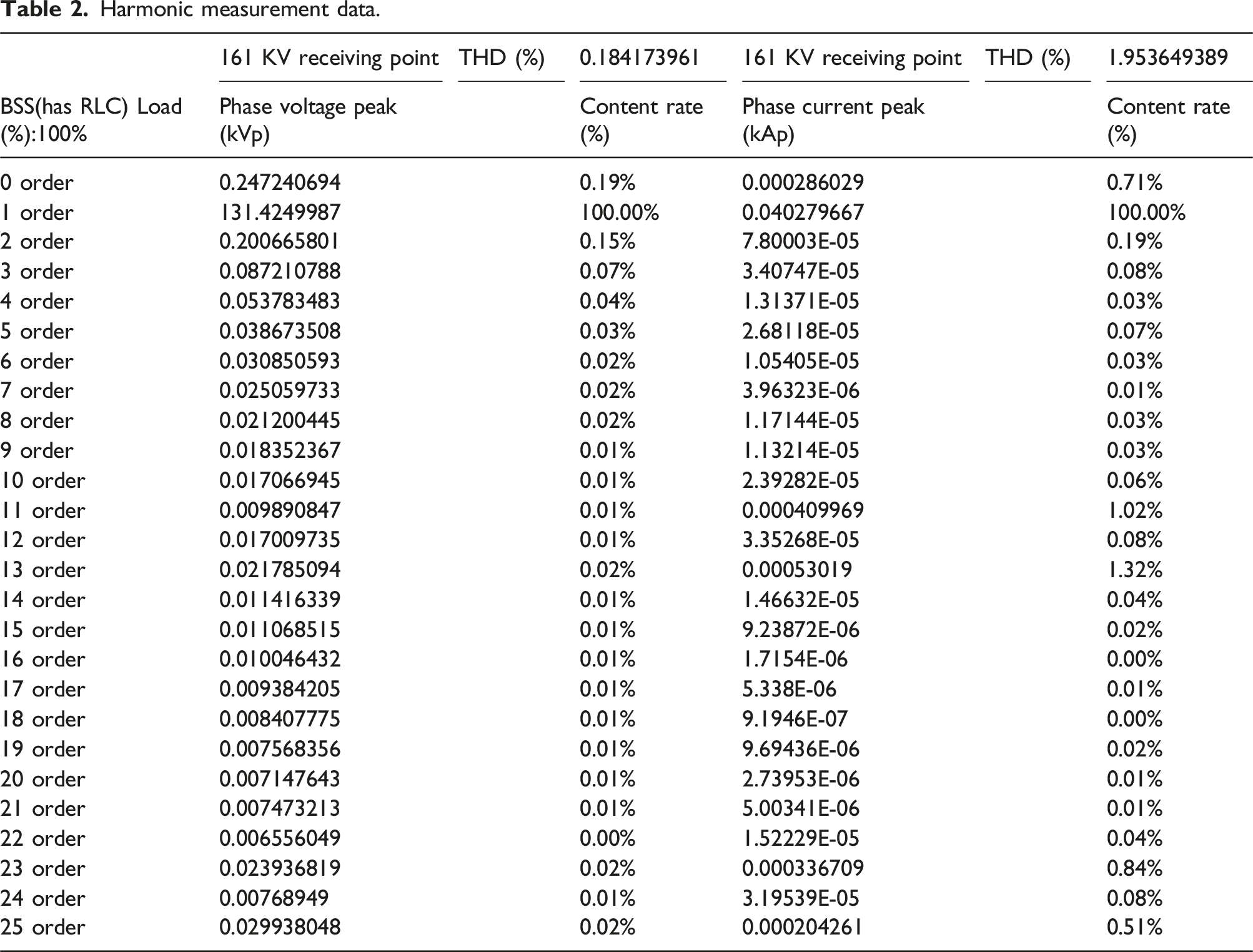
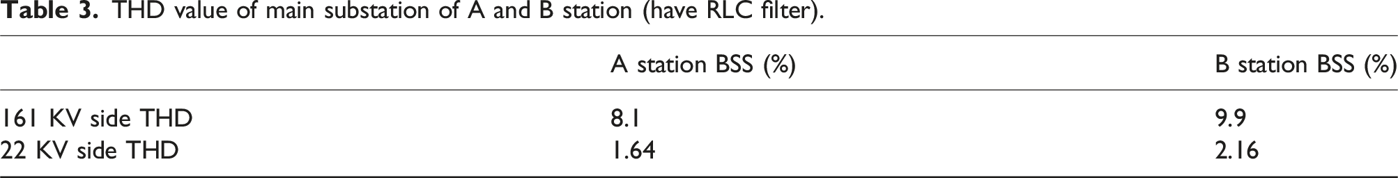
For TSS, the total load THD on the 22.8 KV side is 1.64% + 2.16% = 3.8% (with high-pass filter) (Figure 3.), which is still specified in IEEE-519. Total harmonic distortion in the range of 5% maximum. For the harmonic series of the BSS at station B at full load and half load, only the 13th order (as shown in Table 2) requires a high-pass filter to filter out the harmonics (as shown in Figure 4.). The total harmonic distortion will greatly exceed the standard value of 5%.
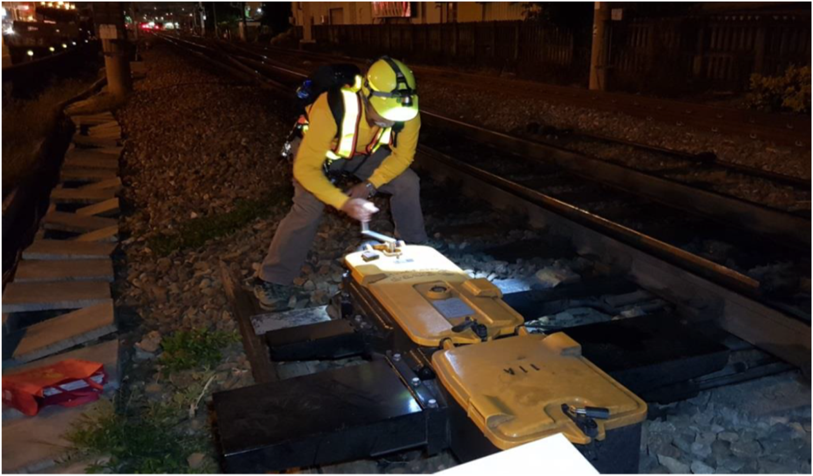
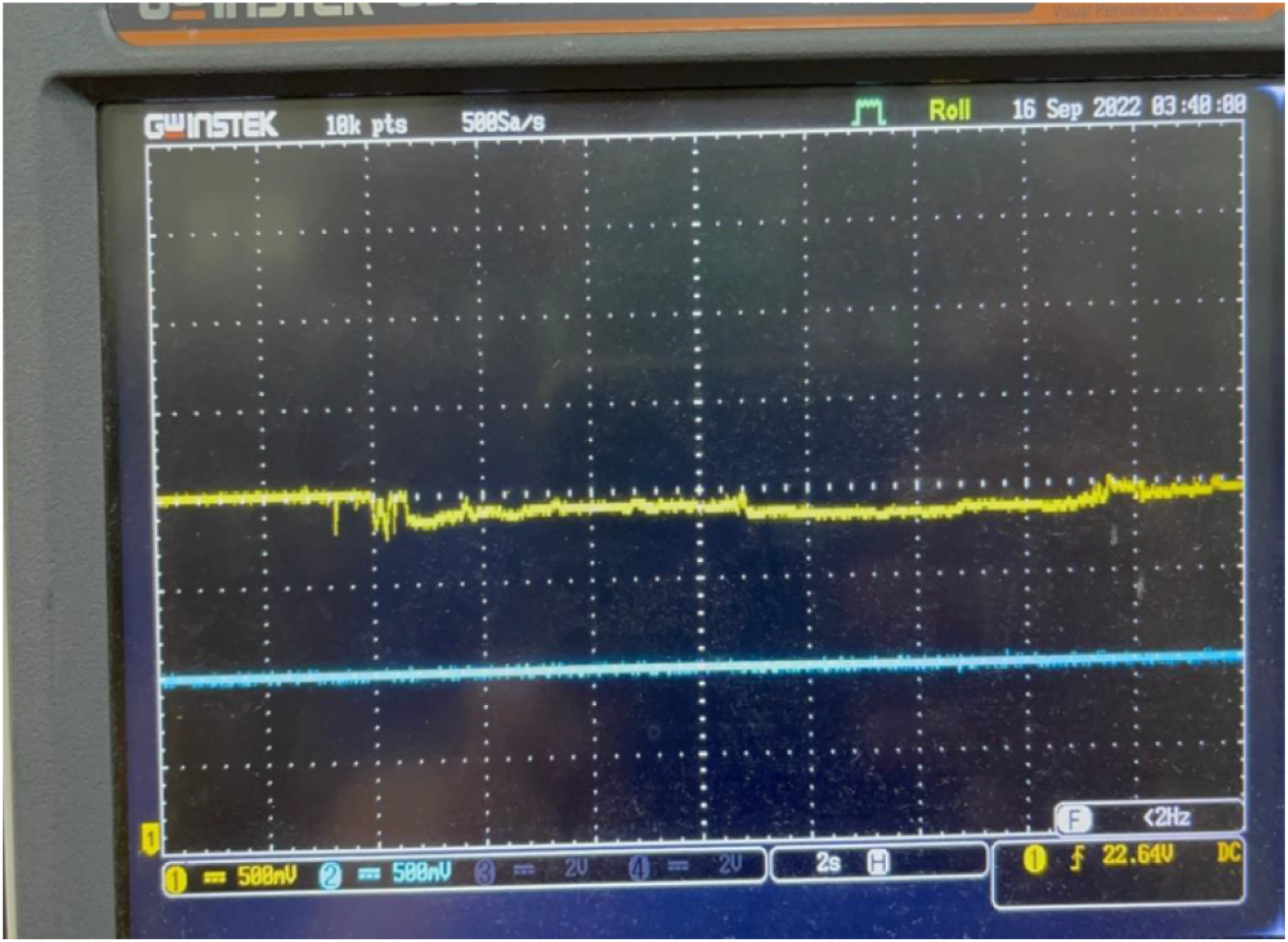
3
Therefore, the installation of high-pass filters in main substations is inevitable. The Taipei MRT system uses a 24-pulse rectifier group, and the rectifier group itself can also be regarded as a parallel resonant capacitor. Although it meets the IEEE-519 total harmonic distortion max 5% requirement at no load. However, at full load, the harmonic distortion rate exceeds the total harmonic distortion max 5%, or even close to 20%. I measured the harmonics on the track (as shown in Figure 5) and found that the track harmonics are unstable waveforms (as shown in Figure 6), it will depend on the measured harmonic source. The closer to loading, the greater the harmonic amount, and the further away, the harmonic amount becomes smaller. High-pass filter. Harmonic measurement data. Schematic diagram between the power substation and the third rail power supply. Harmonic measurement. Harmonic measurement waveform.
1. On-load measurement results of BSS at station A (refer to Figure 7) Measurement harmonic results of BSS at station A.
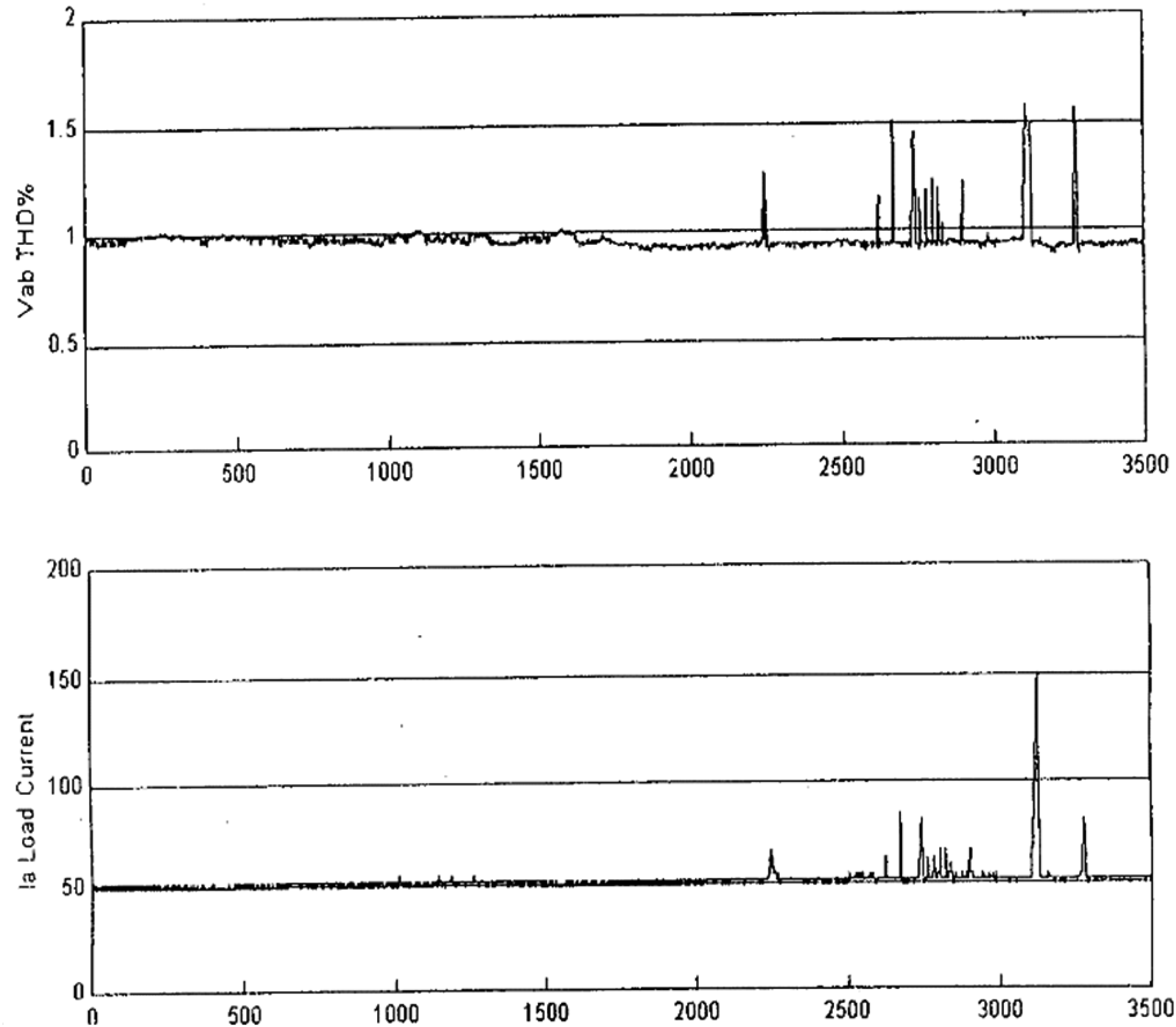
A: On-load harmonic current THD% measured value B: Background carrier harmonic current THD% measured value
A−B: System harmonic current THD% net value C: Total capacitance of harmonic source during measurement
D: Total capacitance of system harmonic source D is the total harmonic amount measured by the system harmonic source.
161KV side:
A = 1.05% , B = 1.00% A23DEB = 0.5% I161KV ≒30A ISSS≒5A ∴ITSS=I161KV−ISSS=25A
C=
According to the MRT Special Technical Specifications: The total amount of system harmonic sources
D = 16.2MVA D: Main transformer capacity D is the total harmonic amount measured by the system harmonic source.
∴ System harmonic distortion THD% = (0.5% × 16.2) ÷ 6.97 = 8.1%
22.8 KV side:
A = 1.5%, B = 0.9% A23DEB = 0.6% ITSS≒150A C=
C: Maximum peak value D = 16.2MVA D: the first Main transformer capacity
D is the total harmonic amount measured by the system harmonic source.
According to the MRT regulations: the total amount of system harmonic sources D = 16.2MVA
∴ System harmonic distortion THD% = (0.6% × 16.2) ÷ 5.9 = 1.65%
2. On-load measurement results of BSS at station B (refer to Figure 8): Measurement harmonic results of BSS station B.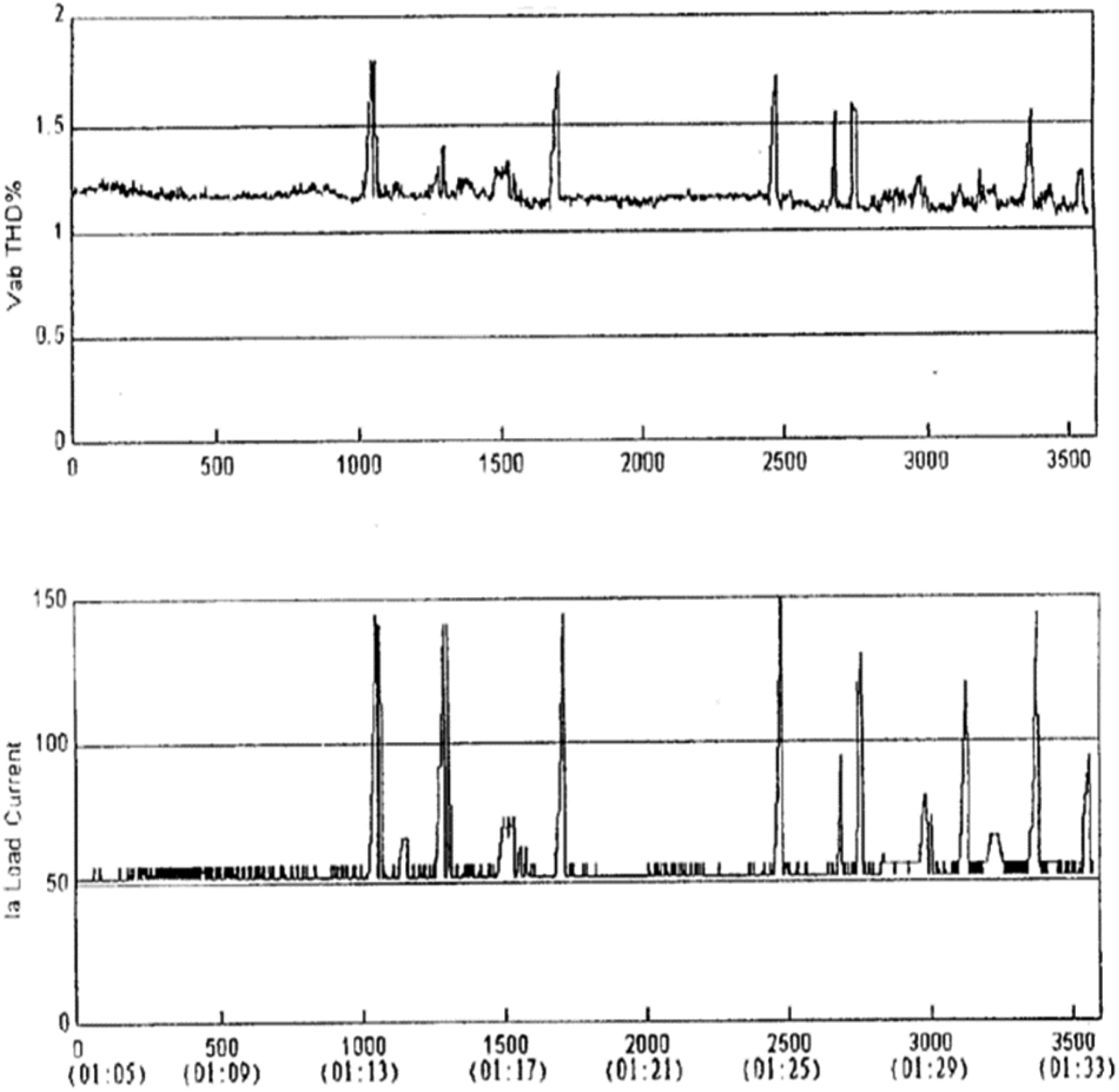
161 KV side:
A = 1.05%, B = 1.00% A23DEB = 0.5% I161KV ≒170A ISSS≒(120A + 125 A)×22.8/161=35
∴ITSS=I161KV−ISSS=135A C=
D = 19.8MVA D: the second Main transformer capacity D is the total harmonic amount measured by the system harmonic source.
According to the MRT regulations: the total amount of system harmonic sources
∴ System harmonic distortion THD% = (0.5% × 19.8) ÷ 37.7 = 9.9%
22.8 KV side:
A = 1.5%, B =0.9% A23DEB = 0.6% ITSS≒150A C=
C: Maximum peak value D = 16.2MVA D: the first Main transformer capacity
D is the total harmonic amount measured by the system harmonic source.
According to the MRT regulations: the total amount of system harmonic sources D = 16.2MVA
∴ System harmonic distortion THD% = (0.6% × 16.2) ÷ 5.9 = 1.65%
2. On-load measurement results of BSS at station B (refer to Figure 8.):
161 KV side:
A = 1.05%, B = 1.00% A23DEB = 0.5% I161KV ≒170A ISSS≒(120A + 125 A) ×22.8/161=35
∴ITSS=I161KV−ISSS=135A C=
D = 19.8MVA D: the second Main transformer capacity D is the total harmonic amount measured by the system harmonic source.
According to the MRT regulations: the total amount of system harmonic sources
∴ System harmonic distortion THD% = (0.5% × 19.8) ÷ 37.7 = 9.9%
22.8 KV side:
A = 1.65%, B = 1.05% A23DEB = 0.6% ITSS≒140A C=
C: Maximum peak value D = 19.8MVA D: the second Main transformer capacity
D is the total harmonic amount measured by the system harmonic source. According to the MRT regulations: the total amount of system harmonic sources
THD value of main substation of A and B station (have RLC filter).
Description of this section
For TSS, the total load THD on the 22.8 KV side is 1.64% + 2.16% = 3.8%, which is still stipulated in IEEE-519. The total harmonic distortion is within the range of max5%;. Based on the harmonic series of BSS at full load and half load at station B, only the 13th order needs to be added with a high-pass filter to filter the harmonics. If the RLC high-pass filter 4 is not installed, the total harmonic distortion will exceed the standard value of 5%. If all three BSS are loaded, one of them cannot supply power, and when the power is transferred from the other two BSS, its harmonic distortion will rise to 18%;(161 KV side), exceeding the 5% standard by many, so A damping unit needs to be added to filter harmonics. Otherwise, it will cause system malfunction and high reactive power, and greatly reduce the output of active power.
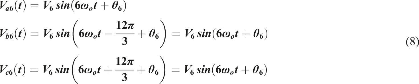
MRT harmonics equation
Harmonic formula
Assuming that the voltage contains harmonic components and is an odd function, it can be expressed as follows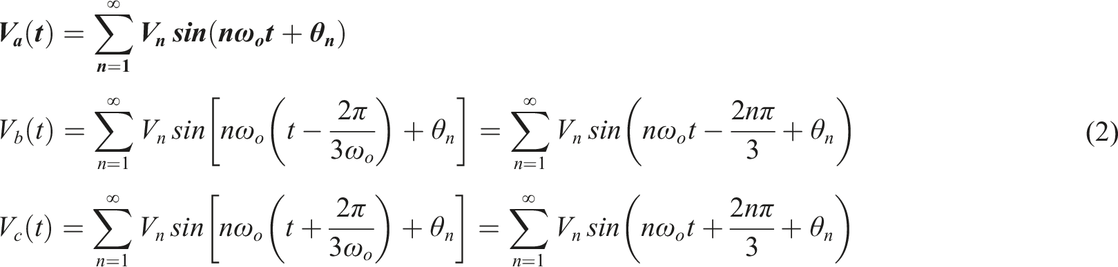
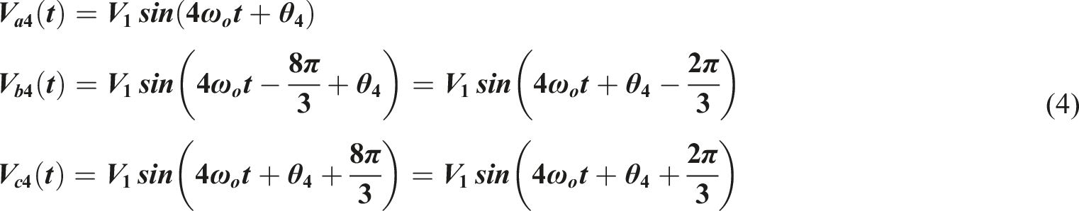
A. Positive phase sequence: n = 3k + 1, k: positive integer (Include 0) ∴n = 1、4、7……
When n = 1, substitute (2)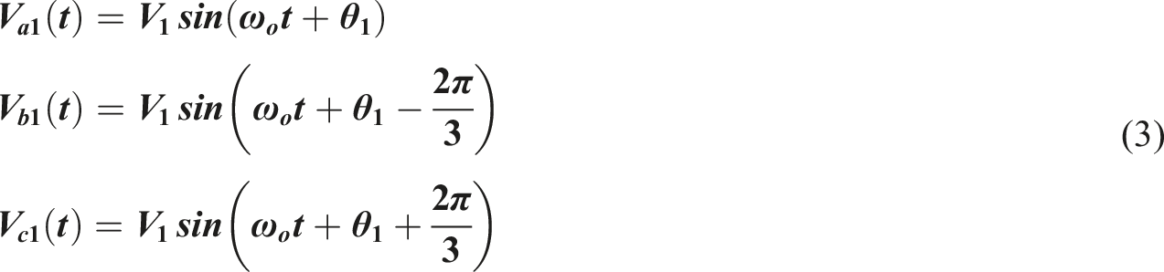
B. Negative phase sequence: n = 3k + 2, k: positive integer (Include 0) ∴n = 2、5、8……
When n = 2: substitute (5)
When n = 5: substitute (5)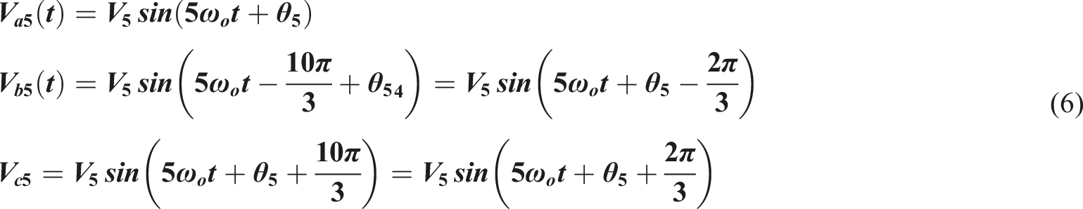
C. Zero phase sequence: n = 3k, k: positive integer (Include 0) ∴n = 3、6、9……
When n = 3, substitute (7)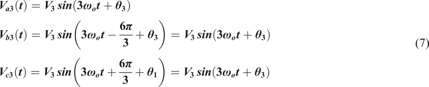
The total voltage harmonic distortion is
(in V2、V3……Vn:RMS value of individual harmonic voltage V1:RMS value of basic harmonic voltage)
The total current harmonic distortion is
(in I2、I3……In:RMS value of individual harmonic current I1:Fundamental harmonic current effective value)
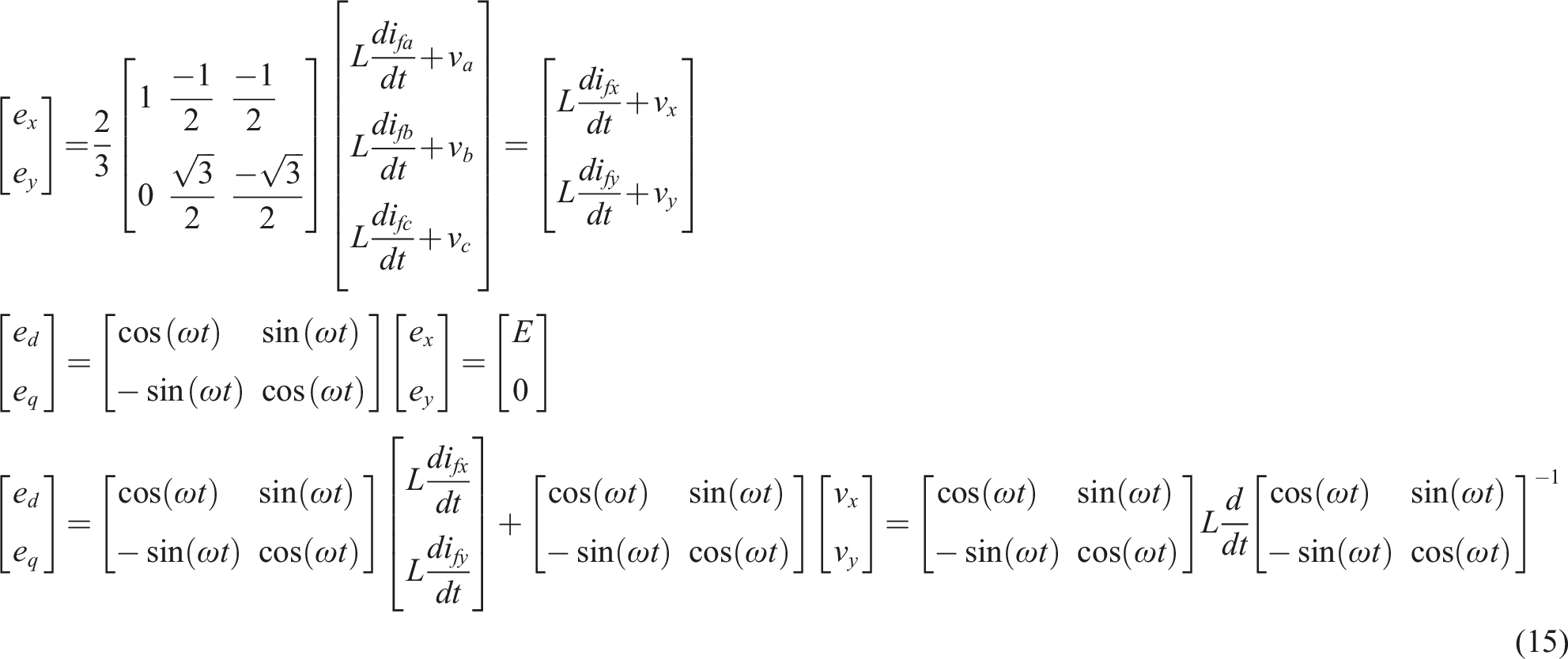
Train drive matrix formula


a - b - c frame to the stationary x - y frame is obtained as follows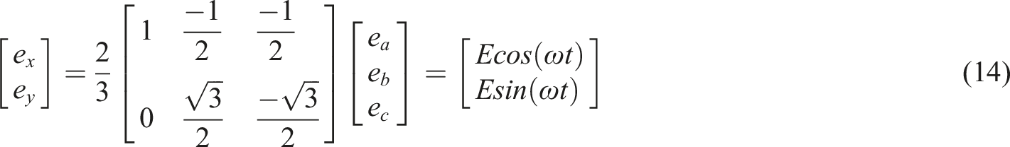

Active power filter principle
Origin of active filter and parallel design of high-pass filter
In 1992, Pinheiro and Barbi proposed a three-level (TL) zero-voltage switching (ZVS) PWM 5 converter. Currently, converters commonly used in the industry are divided into half-bridge and full-bridge circuit filters.
In 2002, Professor Ruan Xinbo proposed the advantages and disadvantages of APF, 6 full-bridge circuits and half-bridge circuits, and called the upper and lower symmetrical circuits cathode and anode circuits. He also proposed that half-bridge symmetrical circuits are superior to full-bridge symmetrical circuits in terms of high-voltage filtering.
In 2009, Professor Hirofumi Akagi proposed that APF should be used in motor control filtering applications. The filtering range of the APF should be within the nonlinear range of medium and high voltage (400 v ∼ 6.6 KV) to effectively filter out harmonics.
7
In the MRT system, it is mostly used to convert the internal power input of the vehicle
8
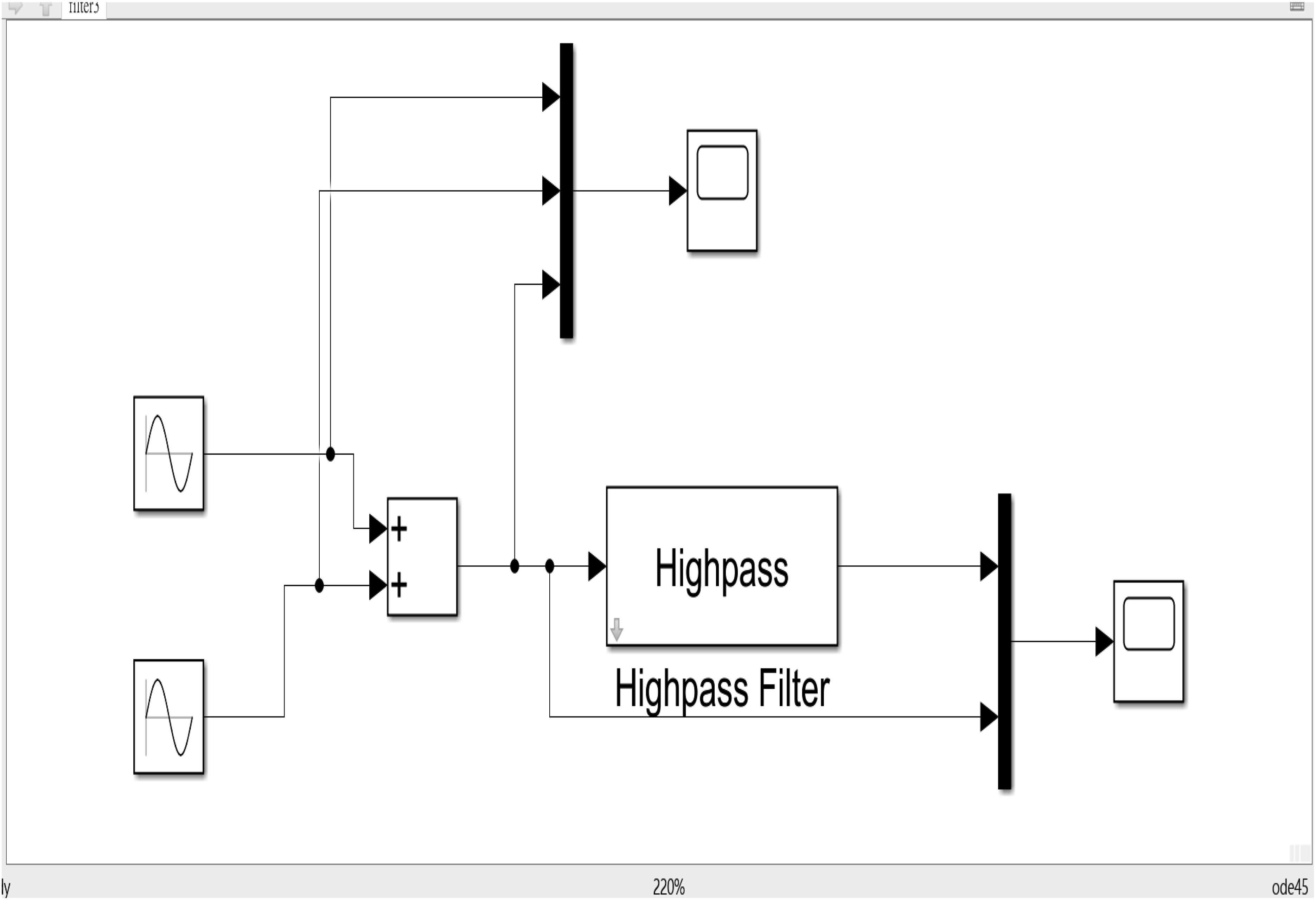
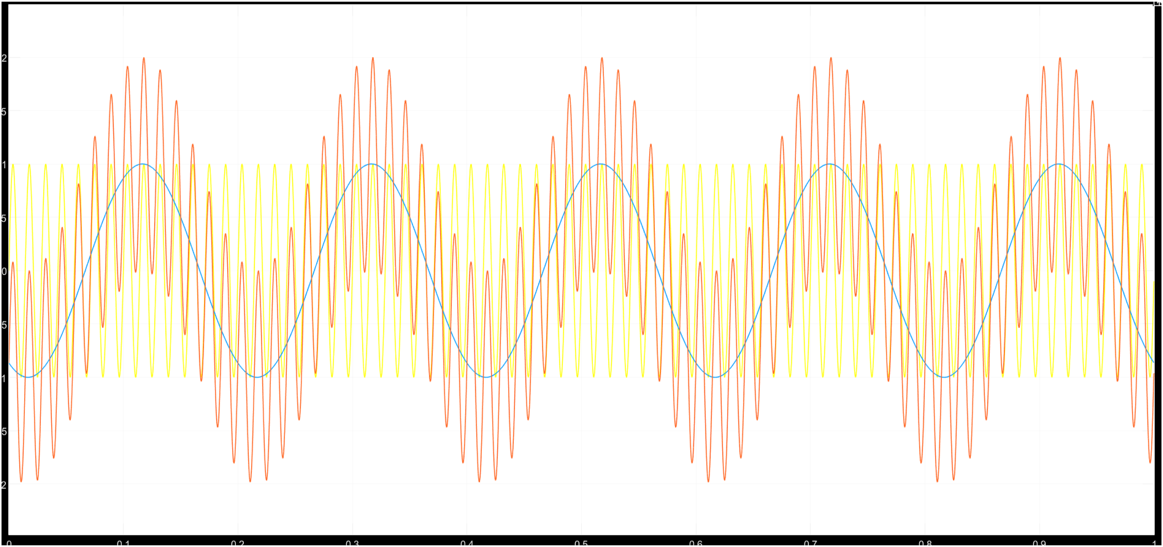
into a three-phase induction motor (shown in Figure 9) to drive the train forward. If used as a filter in a power supply system, the voltage resistance of the diode and transistor must be improved. In addition, the power supply materials must also be changed. I designed a high-pass filter (shown in Figure 10), and the waveform is shown in Figure 11.The harmonics are filtered out first, and then two single-phase high-pass filters are connected in parallel to form a three-phase APF (Figure 12). The input from d-q axis converts to the a-b-c axis output and use the high-pass filter principle to filter out the harmonics of the high-voltage power system to increase the service life of the MRT and enable the normal operation of the train signal. Schematic diagram of three-phase active power filter. Single-phase APF circuit figure. Single-phase APF circuit waveform. Three-phase APF circuit figure.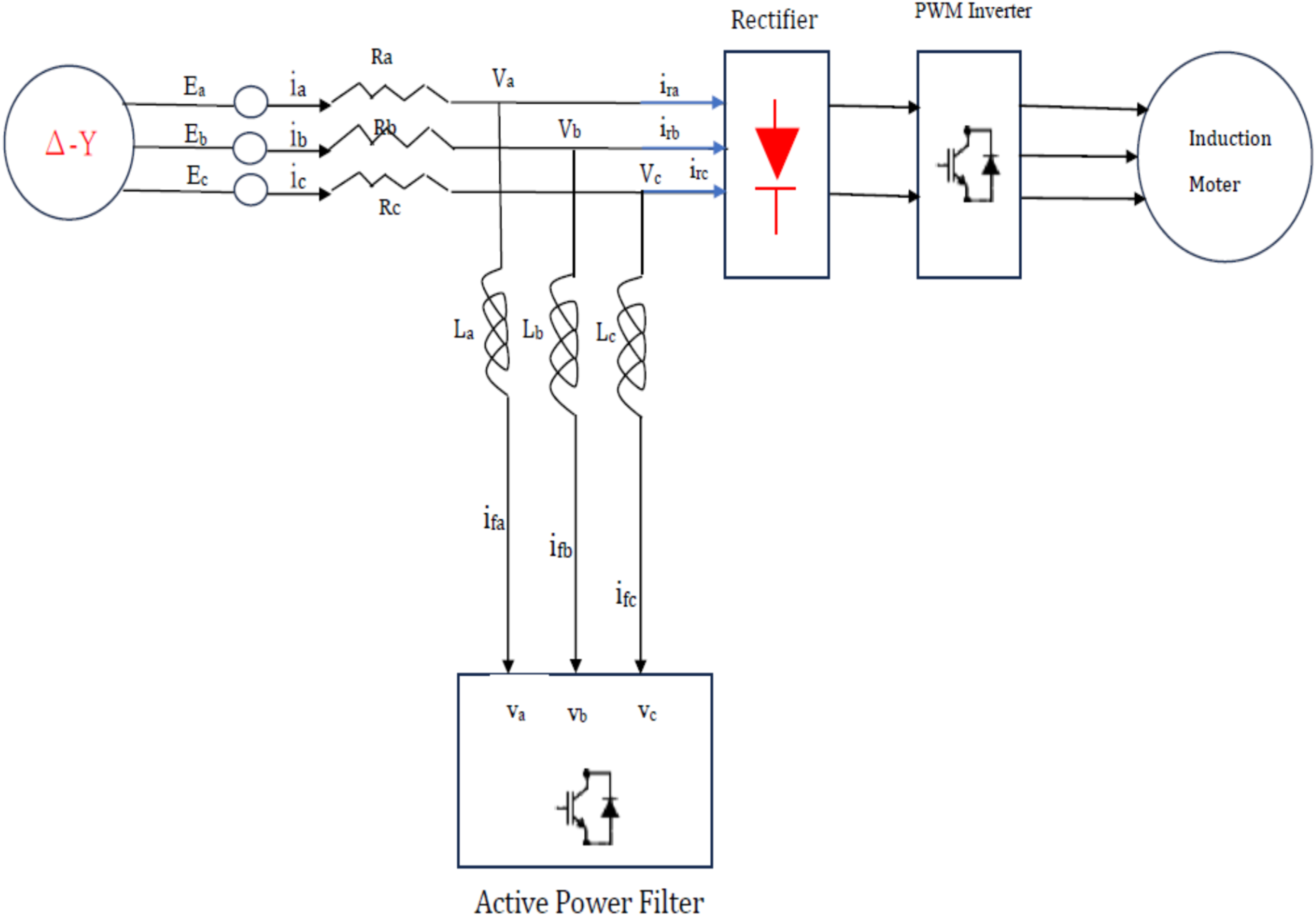
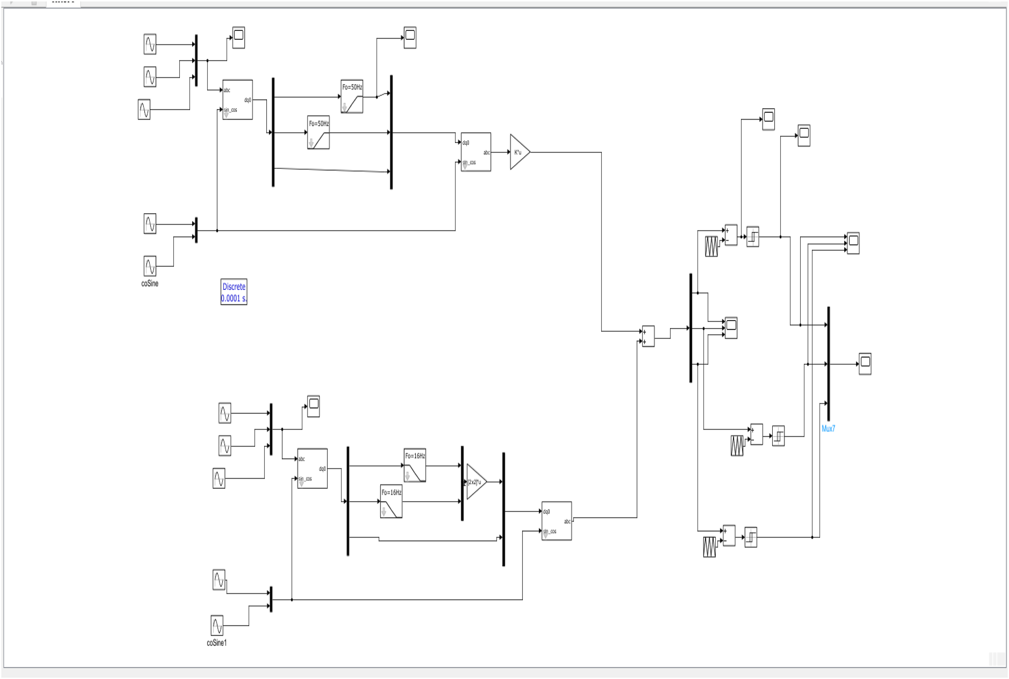
This research is mainly based on Figure 18, an improved double high-pass filter that does not weaken the system power, uses semiconductor materials to replace the electronic passive component RLC, uses the ground wire as the 0° phase sequence, and then connects two +120° and −120° single phase high-pass filters are connected in parallel to form a three-phase high-pass filter, and IGBT components are used to replace the filter for APF proposed by Professor Hirofumi Akagi (as shown in Figure 13). 6.6-KV, 1-MW transformerless adjustable-speed drive equipped with the hybrid filter.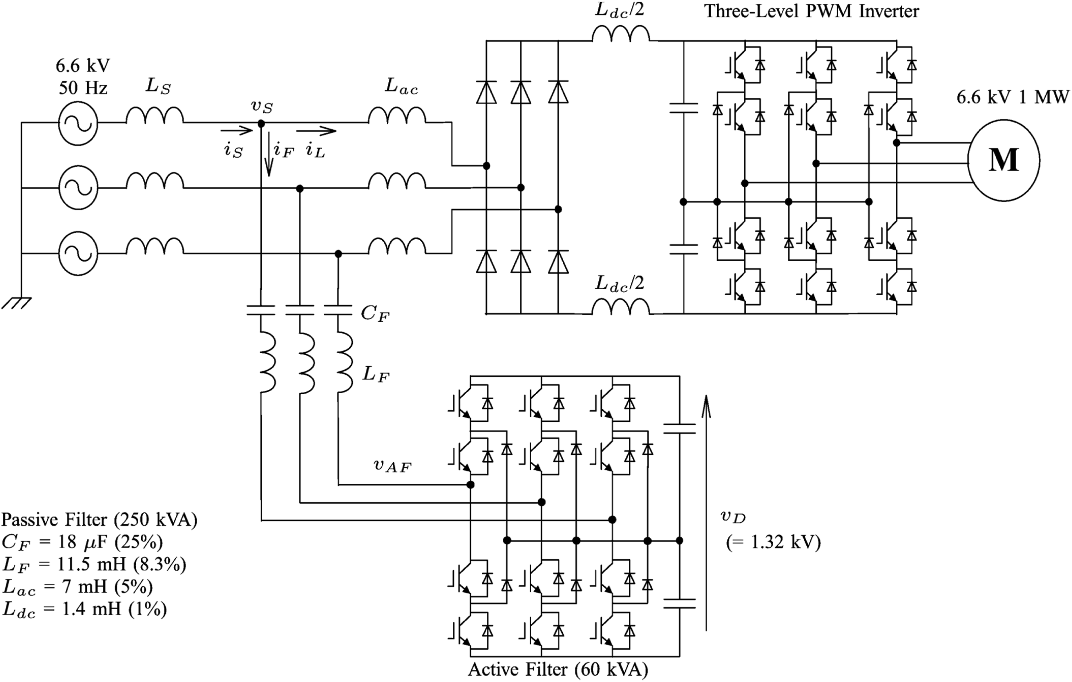
In addition, Akagi only performed simulations at 6.6 KV to eliminate nonlinear harmonics in motors. This study was applied to a 22 KV power system to eliminate nonlinear harmonics. It gave the train a clean power supply environment from the beginning, not only limiting the in-motor applications but the main purpose is also to prevent train signals from malfunctioning and extend the service life of trains.
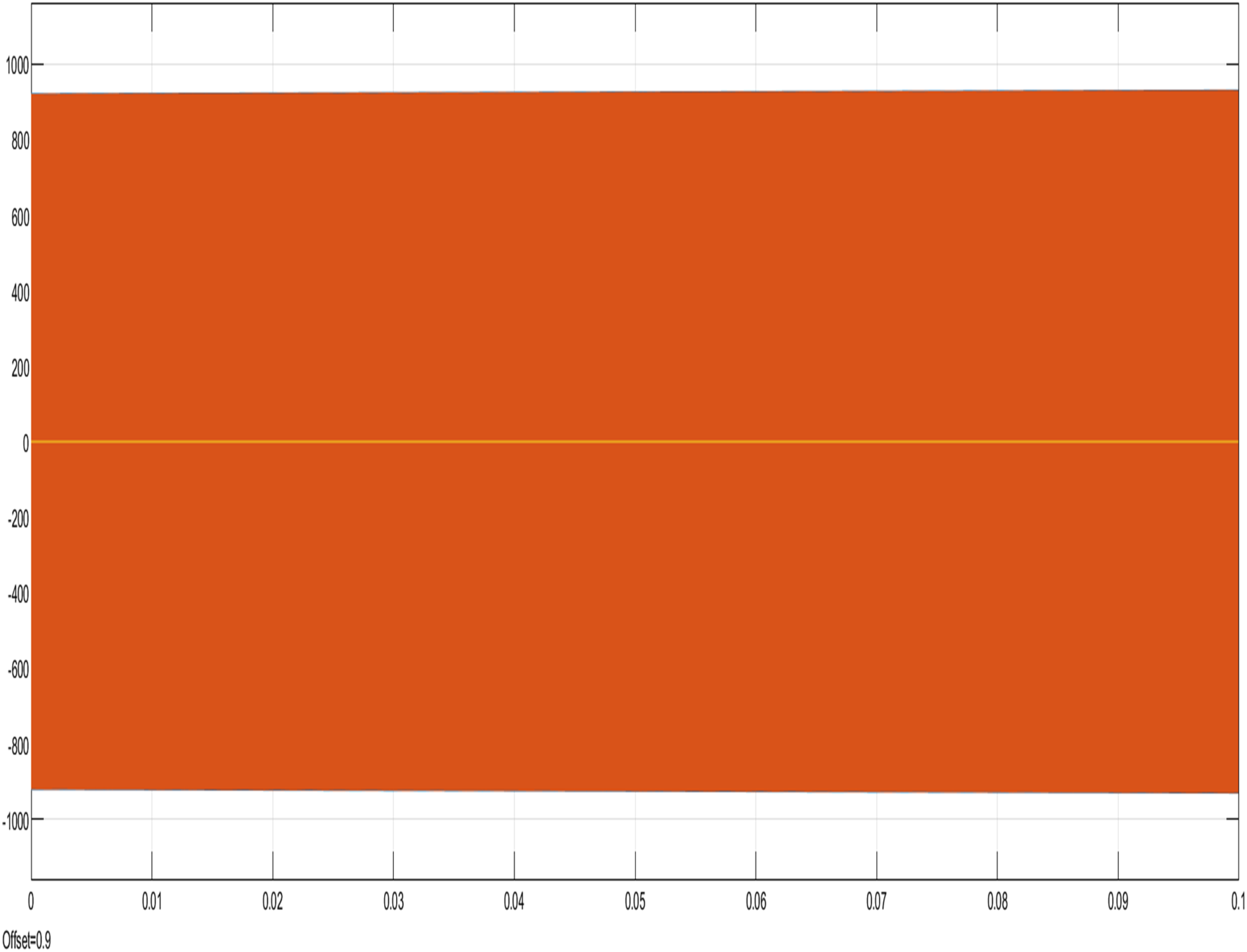
From Figure 23, it can be seen that the three-phase current of the system has no harmonics and no power weakening phenomenon. From Figure 24, it can be seen that the rectification result of the rectifier has no ripples and stably supplies the train DC power supply −850 v to 850v. This is the purpose of this study, and this desired results.
Simulative active power filter to improve harmonic distortion
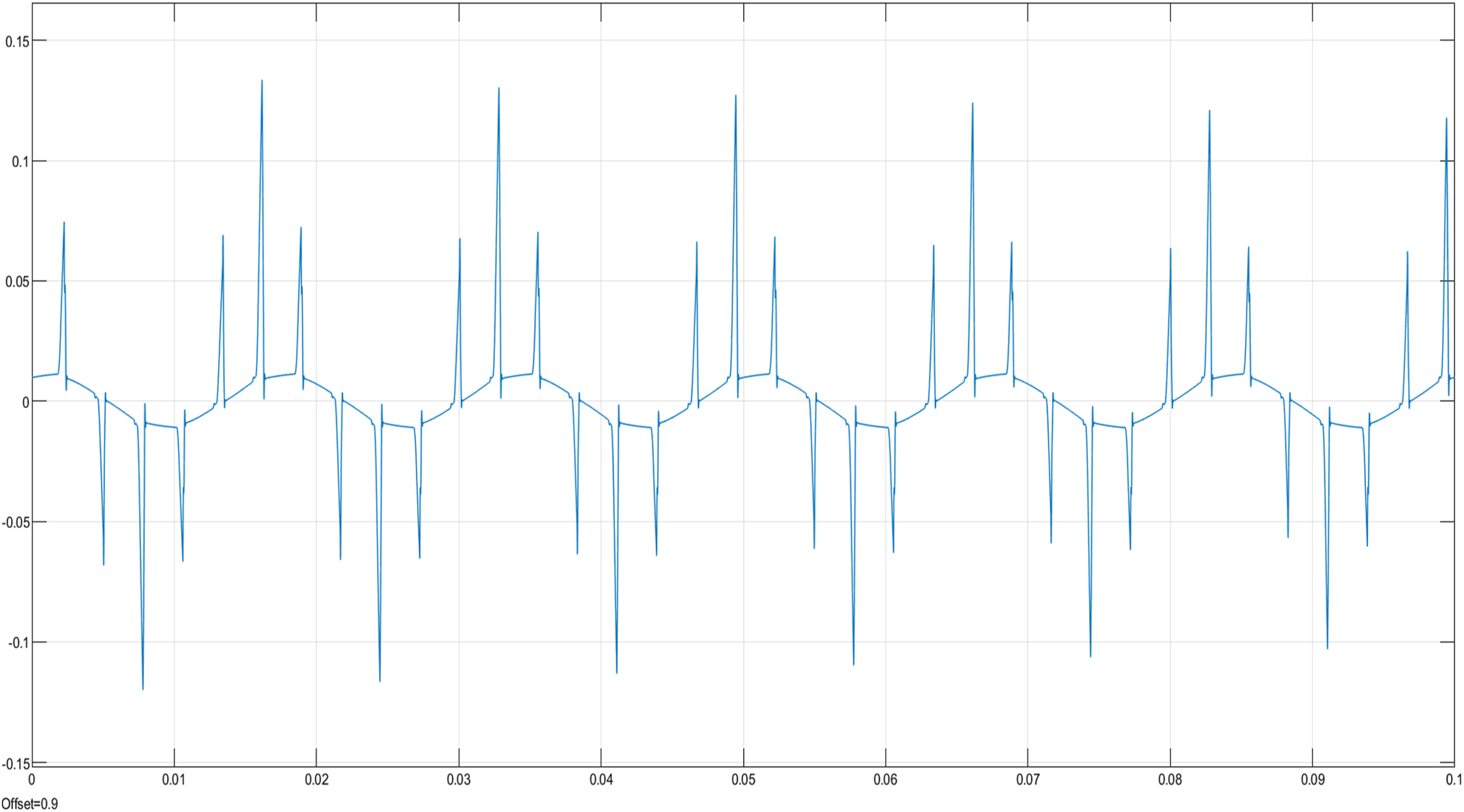
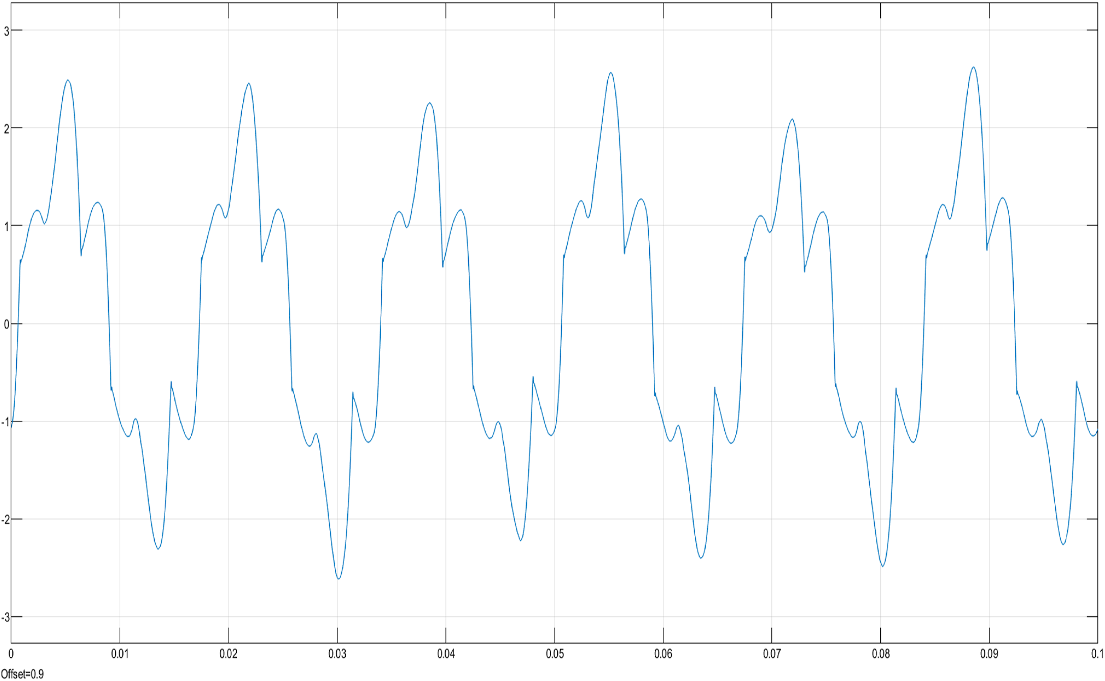
For MRT, the current power supply used by rail trains is alternating current, which cannot directly generate direct current. Since the 161 KV high-power alternating current of BSS itself is a harmonic source, after three-phase rectification, it becomes single-phase direct current, and A phase of the harmonic current will be larger (as shown in Figure 14). If it is to be used in trains, the power system must be rectified.
10
A power supply diagram of the train power system.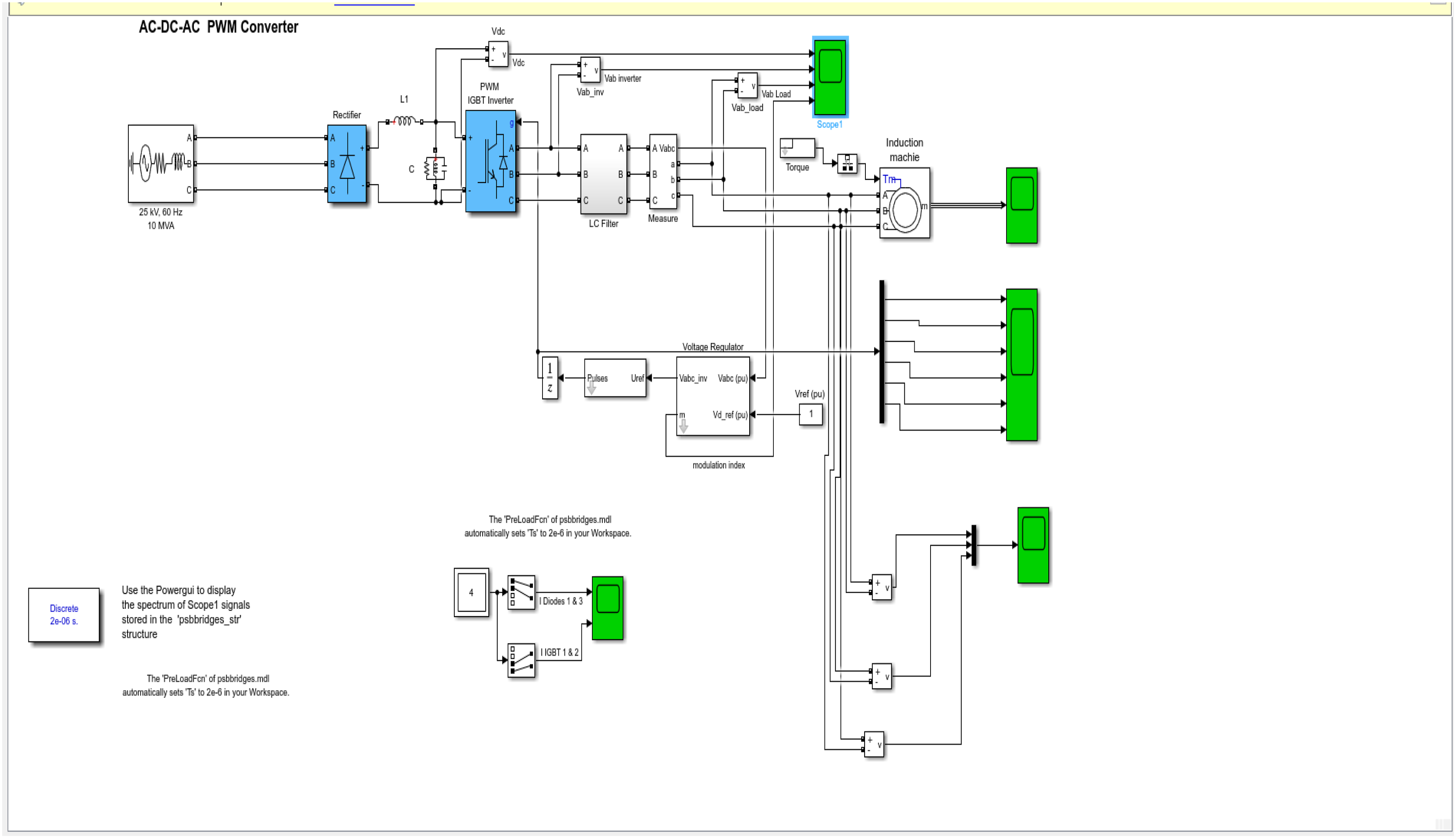
A power supply diagram of the train power system
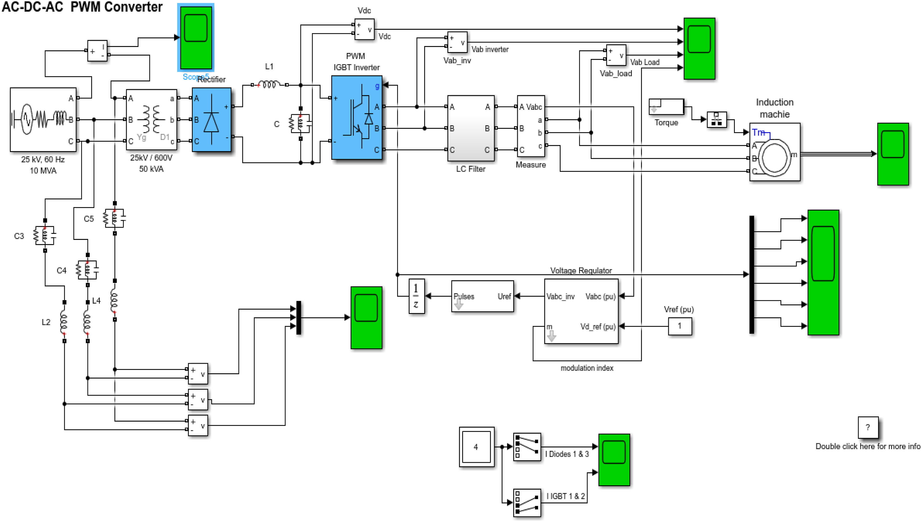
The power system without Three-phase APF circuit: a. Assuming that no power filter is added to the power system, we have designed the power supply diagram of the train power system (as shown in Figure 15).
9
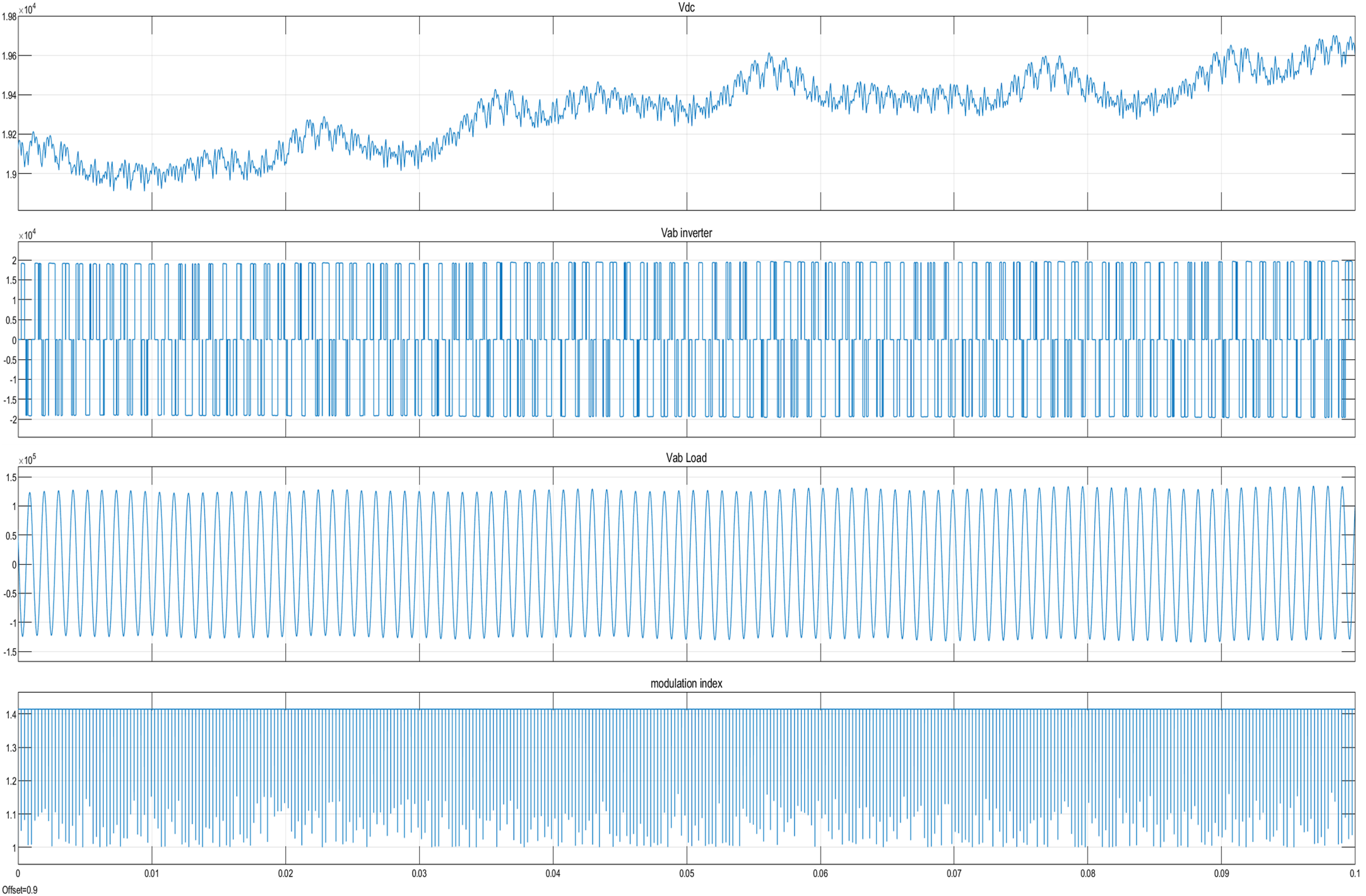
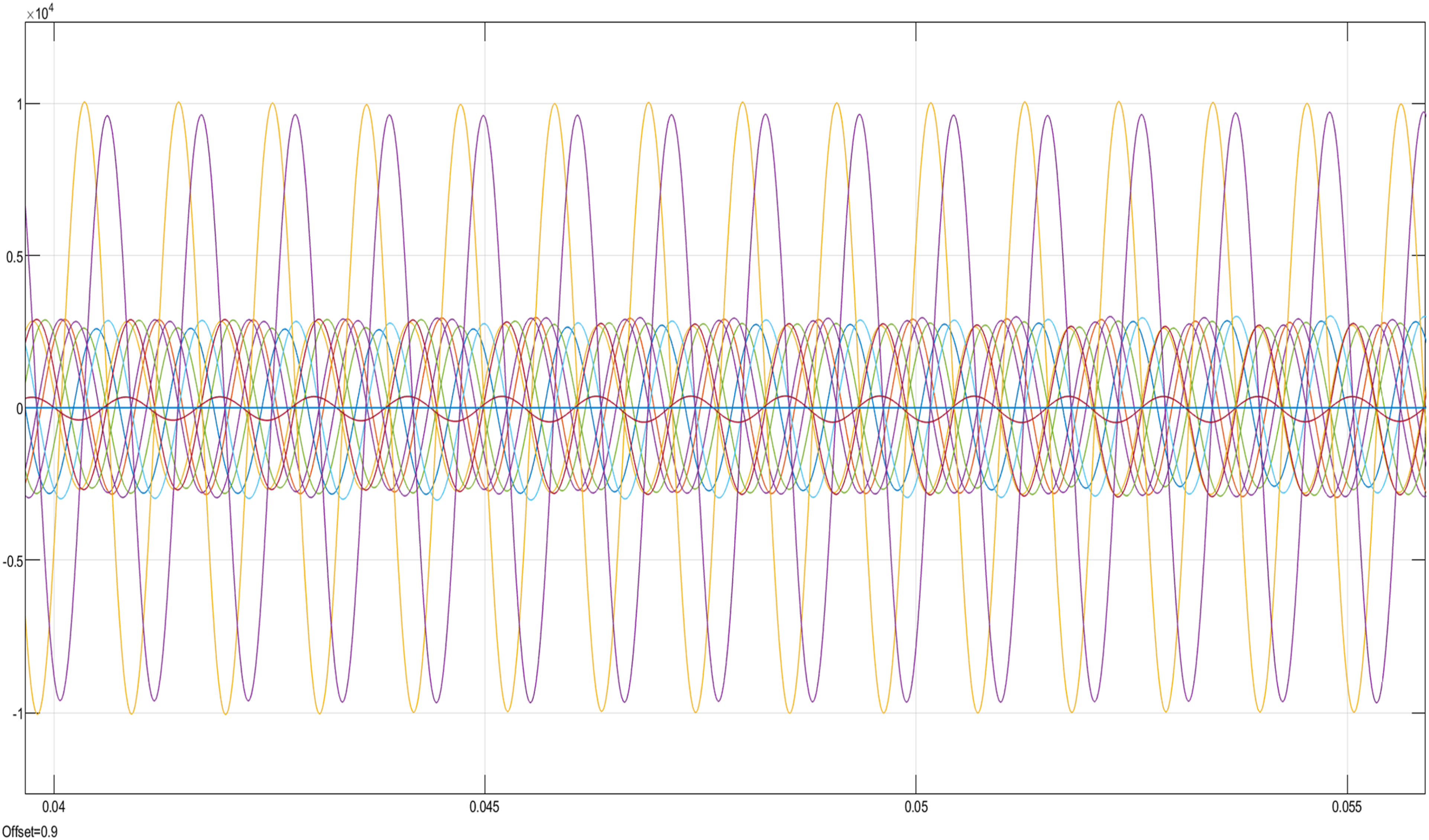
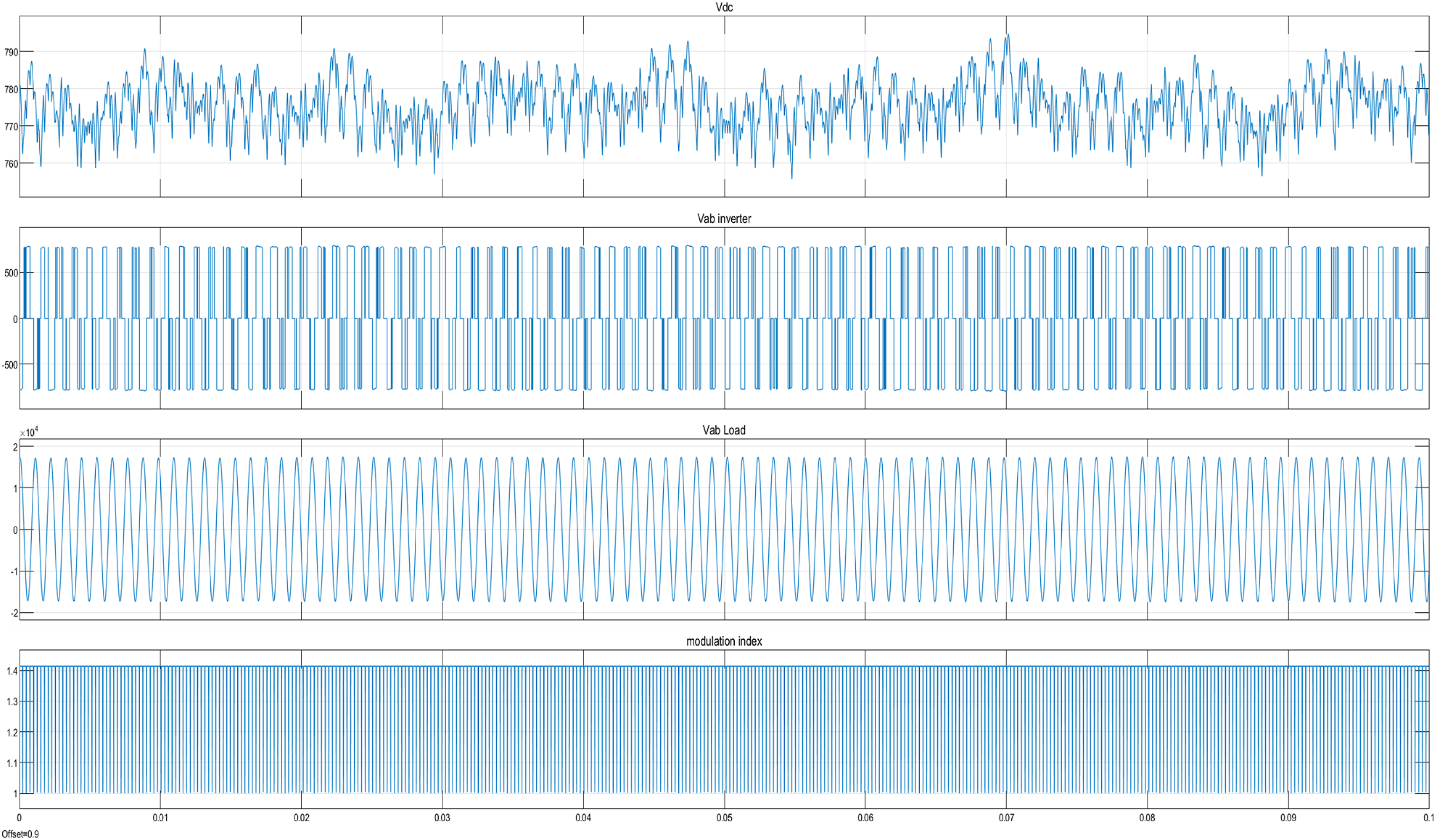
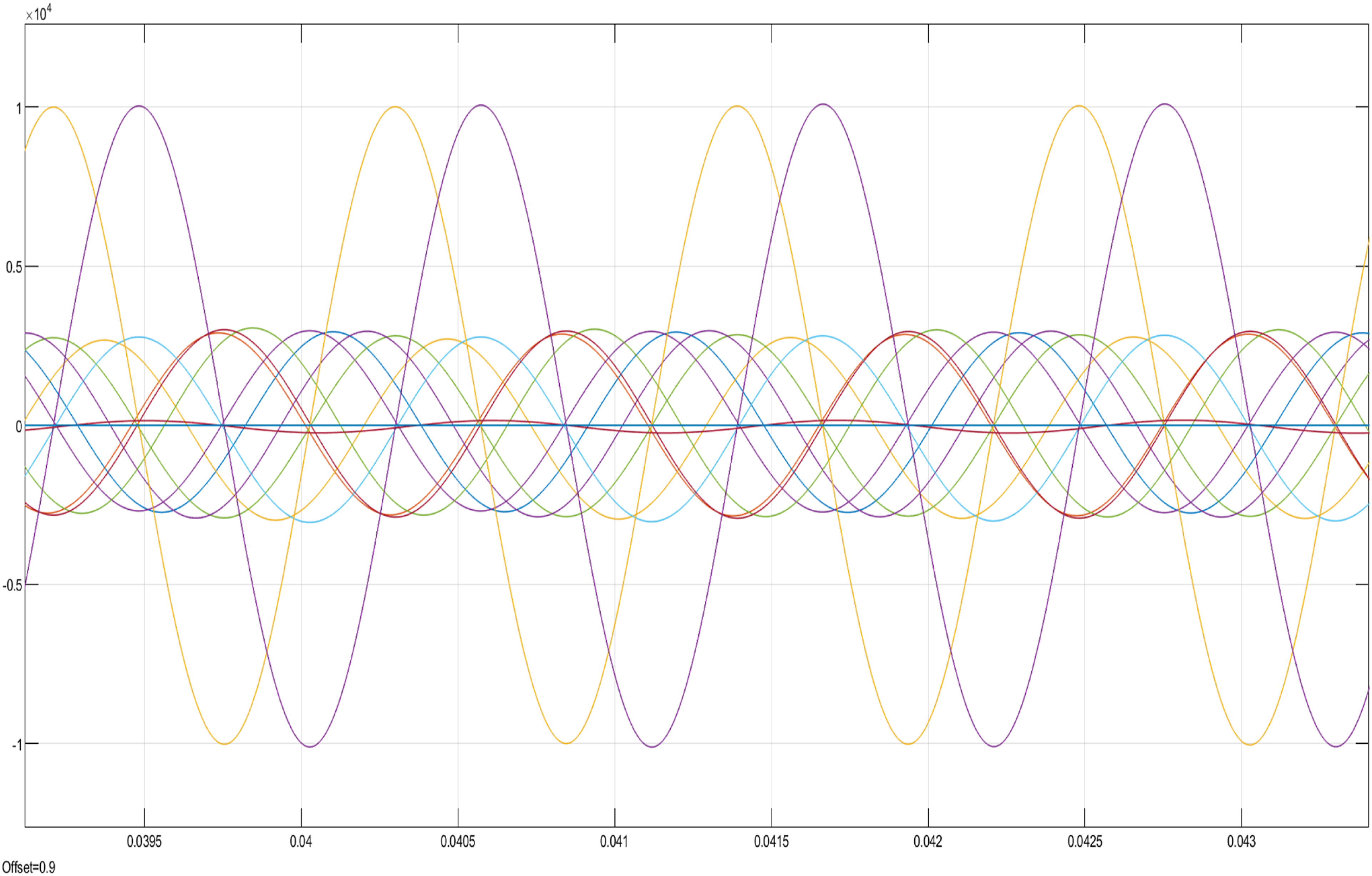
b. It can be seen from scope 1 that the “modulation index” is unstable and Vdc is unstable and the harmonic current climbs upwards. (as shown in Figure 16). c. It can be seen from scope 4 that the stator and rotor harmonics of the induction motor are large and unstable. (as shown in Figure 17). Harmonic current waveform of phase A power supply. Vdc & modulation index is unstable graph. That the stator and rotor harmonics are large and unstable.
A power supply use RLC filter diagram of the train power system
The power system use RLC filter circuit: a. Assuming that no power filter is added to the power system, we have designed the power supply diagram of the train power system (as shown in Figure 18). b. A phase of the harmonic current will be larger and the power gets smaller, (as shown in Figure 19). c. It can be seen from scope 1 that the “modulation index” is stable and Vdc is stable and the harmonic current is not climbs upwards. (as shown in Figure 20). d. It can be seen from scope 4 that the stator and rotor harmonics of the induction motor are small and The power circuit without harmonics after rectification is shown in scope5, but this circuit will be shorten and has small harmonics (as shown in Figure 21.)
11
A power supply use RLC filter diagram of the train power system. Harmonic current waveform of phase A power supply. Vdc & modulation index is stable graph. That the stator and rotor harmonics are small and stable.
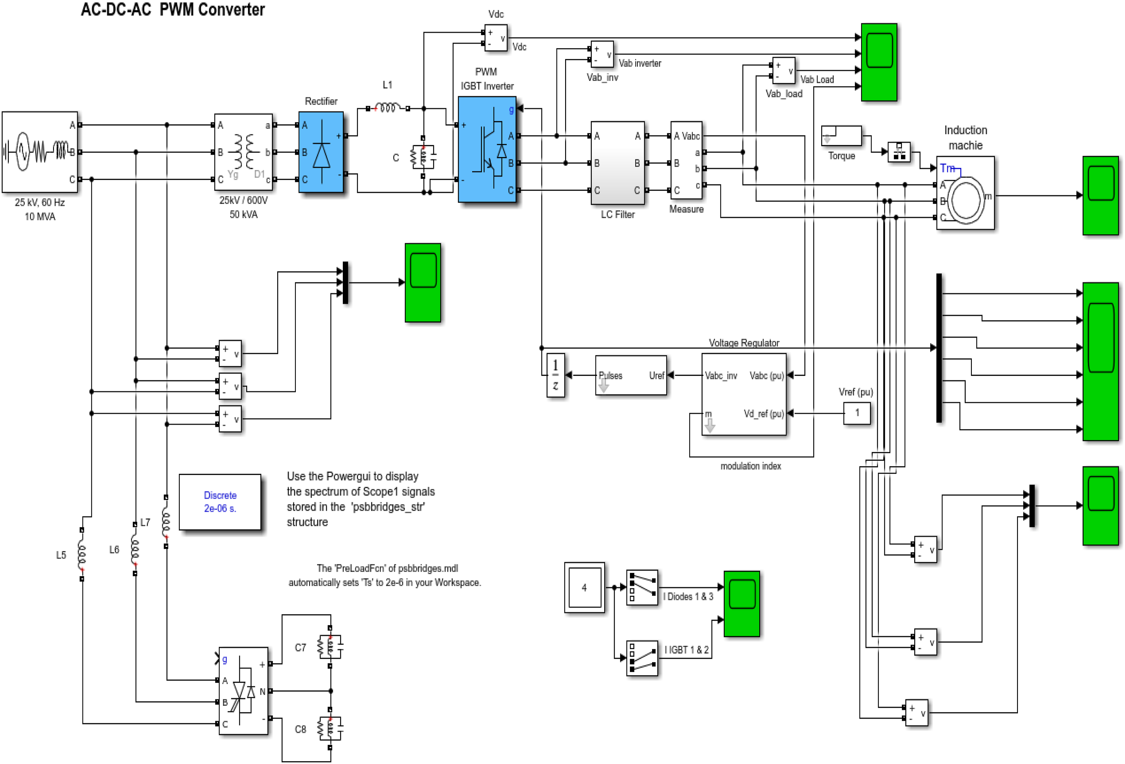
A power supply use APF diagram of the train power system
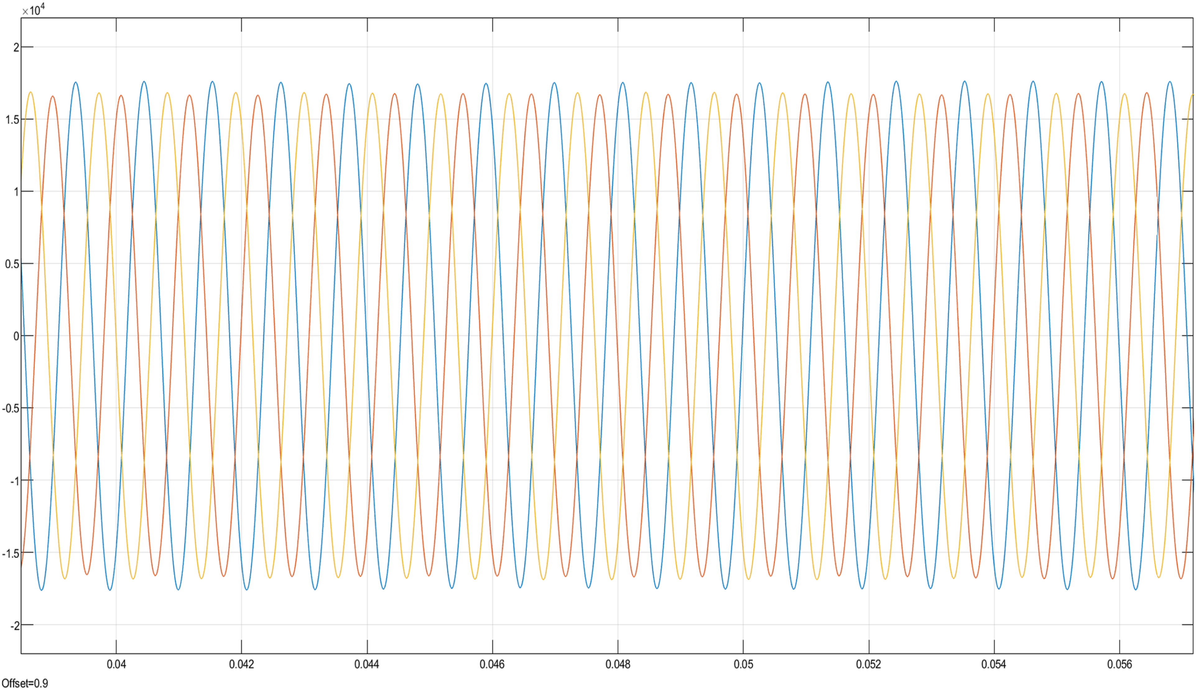
The power system use APF filter circuit: a. Assuming that is added APF to the power system, we have designed the power supply diagram of the train power system (as shown in Figure 22). b. It can be seen from scope 1 that the “modulation index” is stable and Vdc is stable and the harmonic current is not climbs upwards. c. It can be seen from scope 4 that the stator and rotor harmonics of the induction motor are small and table. d. The power circuit without harmonics after rectification is shown in scope5, and this circuit will shorten the life of the motor if it is supplied to the three-phase induction motor (as shown in Figure 23).
11
e. The application range of train DC is DC 750 v ∼ 850 v. It can be seen from Figure 18 that after filtering by APF, the DC power is stronger (almost DC 850 v) and the waveform is more complete (in a straight line). (as shown in Figure 24)
12
A power supply use APF diagram of the train power system. Three-phase power current without harmonics by APF. High-voltage of power circuit without harmonics from −850 v to 850 v after rectification.
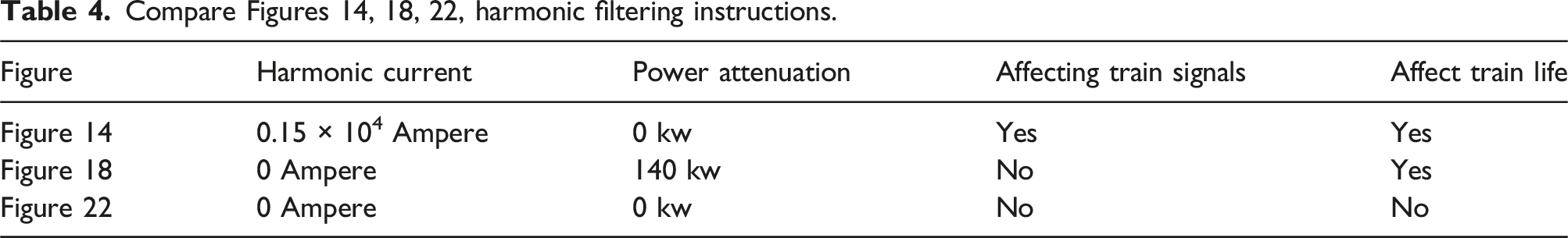
Description of this section
Compare Figures 14, 18, 22, harmonic filtering instructions.
Conclusion
In this study, the range of harmonics to be considered is 22KV ∼ 161KV. On the BSS primary or secondary side, the main consideration is to move the harmonics of motor control to the power system bus to enhance power output and avoid power compensation. The high-voltage diode rectifier controls the harmonic distortion within 5% and meets the requirements of the 519-2014-IEEE, It can be seen from Figure 23 that after APF filtering, almost no harmonics can be seen in the voltage output, After being rectified by the rectifier, the voltage is stably maintained between −850V and 850 V (DC) from Figure 24 which is a major contribution to the shortened life of MRT vehicles, which is the biggest contribution of this study. 13
Although this study uses semiconductor active components as materials to replace RLC or IGBT components, it is known that the heat resistance and service life of semiconductors are not longer than those of RLC or IGBT components, and in the event of failure, the entire set of components needs to be replaced, and a single component cannot be replaced. The operating costs are higher.
In the future, we will continue to study whether in addition to using two high-pass filters in parallel to filter waves, RLC or IGBT components can be integrated into three-phase circuits to reduce the volume of circuit production and reduce production costs.
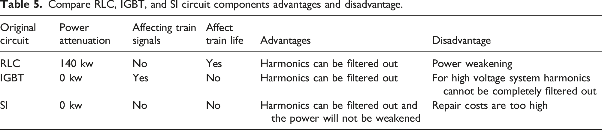
Compare RLC, IGBT, and SI circuit components advantages and disadvantage.
Footnotes
Declaration of conflicting interests
The author(s) declared no potential conflicts of interest with respect to the research, authorship, and/or publication of this article.
Funding
The author(s) received no financial support for the research, authorship, and/or publication of this article.