
Abstract
The article identifies some of the forces acting on hydraulic valves used in the civil and military vehicles. Particular attention was paid to the single-stage electrically controlled “on/off” hydraulic directional control valve. Special attention was focused on vibrations of hydraulic directional valve four ways, three positions (4/3) controlled by typical solenoids. Military vehicles can be a source of vibrations in low and high range of frequency. The spectrum of vibrations frequency is wide in this case. The value of the natural frequency of vibrations of the hydraulic directional control valve spool, whose body was affected by mechanical vibrations, was estimated. The paper shows that the natural vibrations of the directional control valve spool can coincide with the frequency of external vibrations acting on the valve from the ground. The mathematical description takes into account that when the spool is overdriven, the oscillating movement of the directional control valve spool is described by a model that takes into account the nonlinearity resulting from the fact that the spool is in the extreme position—it is a poor nonlinear mechanical system. The results of theoretical considerations were confronted with the results of experimental research. In addition, the presented modified model was used to assess the impact of the capacitance change on the value of the amplitude of pressure pulsations caused by the vibrations of the directional control valve spool.
Introduction
Despite the growing competition from electric and pneumatic drives, hydraulic systems are still widely used. They can be found mainly in technological and mobile machines,
1
ships,
2
and aircraft.
3
They are also widely used in military vehicles, mainly due to the possibility of transferring high power.
4
Their use in military applications is also determined by precision, durability, and reliability.5,6 Hydraulic systems of military devices and vehicles can be successfully operated in difficult environmental conditions.
7
Hydraulic components and systems are used in armored combat earth moving machines. The tasks of these machines operating in difficult environmental conditions are eliminating enemy obstacles, creating and maintaining supply routes for combat units, and creating combat positions. Hydraulic systems are also used in high-mobility vehicles for rescue tasks that involve recovering damaged heavy vehicles. High traction power is obtained in this type of vehicle thanks to the use of high-pressure hydraulic systems. The precision of motion achievable in hydraulic systems8,9 makes them used in systems for loading heavy weapons on various devices and vehicles (some examples with functionality are show in Figure 1). However, machines and devices with hydraulic systems are the source and receiver of vibrations, in which frequencies range from a low of a few Hz to a high of kHz. Examples hydraulic power drive use in military vehicle.
A working machine may generate vibrations, for example, from unbalanced rotating parts and vibrations of a working internal combustion engine.
10
On the other hand, a mobile machine moving on an uneven ground is a vibration receiver.11,12 In both cases, the vibrations are transmitted to the frame of the machine or vehicle and then to all equipment elements, including hydraulic elements. The machine operator is also subjected to mechanical vibrations.
13
For a tank, vertical vibrations in the plane of the driver’s seat and during movement in the field are in the frequency range of 4–8 Hz, and the average amplitude of these vibrations is about 7 m/s2, and the maximum amplitude is as much as 122 m/s2.
14
Civilian vehicles can be a source of vibrations with a wide vibration frequency range. According to literature research studies,15–17 in machines and devices operating in real conditions, among a wide spectrum of vibration frequencies, there are also mechanical vibrations with frequencies of several tens of Hertz.
18
This was confirmed by our experimental research (Figure 2). The average 1/3 octave spectrum of vibration of the frame of the construction loader Ł-220, manufactured by Bumar-Fadroma. Spectrum limited to 80 Hz.
Mechanical vibrations of the Ł-220 construction loader were identified, with particular emphasis on frequencies below 100 Hz.
19
Figure 3(a) shows a hydraulic power pack with a hydraulic directional control valve mounted on the plate. Measurements of vibration of the hydraulic supply unit plate are shown in Figure 3(b) as an amplitude–frequency spectrum in steady-state operation. View of the test of hydraulic power pack with control valve: (a) hydraulic power unit with an integrated directional control valve; (b) vibration spectrum of the hydraulic power unit tank plate.
The dominant frequency in the spectrum (Figure 3(b)) results from the relationship

The tested power supply was equipped with a PNZ-25 multi-piston pump driven at n = 1500 r/min and with z = 7 pistons, that is, according to the relation (1) f 1 = 175 Hz.
Also, other mobile vehicles are vibration generators acting on the elements of the hydraulic system. The car body as a non-deformable body on springs is characterized by vibrations in the range of 2–5 Hz and with amplitudes of 78.5 m/s2, while the body as a deformable system is characterized by vibrations in the frequency range of 60–120 Hz and with an amplitude of 1 g. 20 Horizontal vibrations of railway wagons caused by their joining are in the range of 6–9 Hz, and the amplitude is even over 140 m/s2, while vertical vibrations resulting from the impact of wagon wheels on the rail joints are in the frequency range of 8–30 Hz and the amplitude exceeds 20 m/s2. 21 Even greater excitations act on the elements of the hydraulic system of sea-going ships because they are subjected to vibrations with frequencies up to about 12 Hz, but with significant amplitudes of even over 1500 m/s2. 22 In typical previous applications, hydraulic valves are mounted directly to the frame or other structural elements of the machine, transferring vibration energy to the bodies of hydraulic valves without dissipation. If the vibration frequencies of the valve body and the natural frequencies of the associated valve control element (the clone and spool) are similar, mechanical resonance of the control element occurs. The natural frequencies of single-stage hydraulic valves (relief valves, directional control valves) are usually below 100 Hz.
Theoretical description of the on/off single-stage directional control valve in the overdriven state
As the introduction mentions, the frequency range of vibrations acting on hydraulic valves is wide. In the frequency spectrum, there are many components with different frequencies. These are not only successive harmonics of the fundamental component of the spectrum, but there are vibration components whose frequencies are unrelated because their causes are different. Therefore, the excitation signal in the form of vibrations acting on the valve body (especially directional control valve) can be represented as a sum of sines with different amplitudes and frequencies


Equation (3) presents a decomposition approximating the function w(t), where w 01 —the amplitude of the first component of the vibration spectrum with the fundamental frequency f 01 ; w 02 —the frequency of the first component of the vibration spectrum with the fundamental frequency f 02 ; w 03 —the amplitude of the first component of the vibration spectrum with the fundamental frequency f 03 ; and i—spectrum component number.
In the analyses, a simplified model of external mechanical vibrations was adopted, taking into account the first component of the sum appearing in equation (2) in the following form

The mathematical description of the oscillating movement of the valve spool starts with the balance of forces acting on the valve spool. Figure 4 shows a schematic of the directional control valve spool inside the single-stage four ways three positions directional control valve body, and the forces acting on it are marked. The spool is driven by external on/off solenoid force. Forces balance on the spool of the single-stage directional valve whose body vibrates: 1—electromagnet, 2—valve body, 3—spool moved to its extreme position: Fb—inertia force, Fs—springs force, Fd—hydrodynamic force, FM—electromagnet force, Ft—friction force.
Before proceeding with the mathematical description of the vibrating hydraulic directional control valve, the following detailed simplifying assumptions were adopted
23
: • The effect of pressure pulsation due to pump efficiency pulsation is neglected; • The valve body and the spool are non-deformable; in addition, the valve is non-positively mounted to the ground; • Due to the fact that the oil mass associated with the moving slider is small, the oil mass was omitted from the considerations; • A description of the system by means of lumped parameters on the points of the system was adopted, which involves the use of ordinary differential equations; • Hydraulic conduits are characterized by active resistance, inertia, and capacitance concentrated at the points of the considered system; • Pressure drop in hydraulic lines have been omitted; • The hydraulic oil does not change its viscosity and bulk modulus; • There is no cavitation of the working medium; • The external gear pump is driven at a constant speed, regardless of load fluctuations.
Due to the specific of the construction of the directional control valve (especially the spool), the transverse forces are omitted, and the analysis concerns the longitudinal forces acting on the spool of the vibrating directional control valve. The longitudinal (axial) force needed to override the spool should be greater than the sum of the other forces acting on the spool: the inertia force of the spool, the friction force between the spool and the single-stage four ways three positions directional control valve body, the force from the centering springs, and the hydrodynamic force related to the change of momentum of the liquid stream flowing through the slot the directional control valve throttle formed between the slider piston and the directional control valve body. The inertia force F
b
can be described by relationship

In addition, 1/3 of the mass of the springs centering the slider in the neutral position is included in the weight of the slider.
The Coulomb friction can be neglected in the conditions of hydrodynamic lubrication between the spool and the directional control valve body. The fluid friction model can describe good lubricating conditions prevailing in the sliding pair
24

The spool is affected by hydrostatic forces from the liquid that flows in the gaps between the spool and the directional control valve body. The pressure difference causes the liquid flow. However, these forces can be neglected because the faces of the spool pistons are equal.
Considering the forces acting on the slider, the hydrodynamic force cannot be omitted, the value of which, in the case of high flow rates of liquid through the spool, may exceed the value of the control force coming from the electromagnet coil. The force associated with the change in momentum of the fluid stream flowing through the throttling gap of the valve acts on the spool and on the fluid.
25
The hydrodynamic force, which has a constant and a variable component, is described by the relation24,26

The variable component of the hydrodynamic force is important for unsteady flow and results from the need to accelerate the liquid column. The hydrodynamic force (after omitting the component for unsteady flow in quasi-steady conditions) can be finally written
24


The geometry of the single-stage four ways three positions directional control valve is shown in Figure 5. The geometry of the body-spool system of the single-stage four ways three positions directional control valve.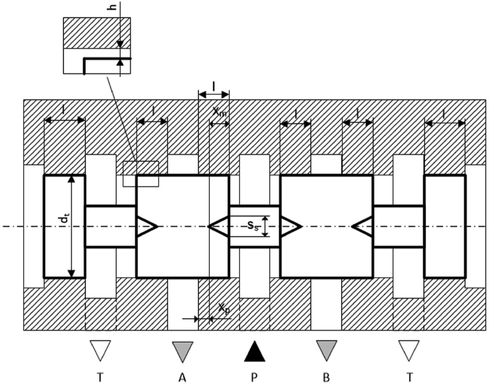
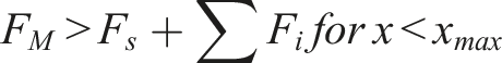
Of the forces acting on the directional control valve spool, the centering forces generated by the pair of springs are the largest. They ensure that the spool returns to the neutral position when the control force from the electromagnet ceases to operate. For the spool to overdrive, the following condition must be met by the directional control valve

Finally, an equation can be written that is the sum of the forces acting on the slider at steady state

The specific of the construction of the single-stage four ways three positions directional control valve and the method of its control show that after overriding the directional control valve, its spool is in an extreme position. On the one hand, it rests against the directional control valve body; on the other hand, it is acted on by the electromagnet armature - Figure 4. Then the paths of transmission of the external mechanical vibrations to the spool are different and depend on the direction of movement of the spool and the way it contacts the valve body. Once the vibrations of the valve body are transmitted to the spool by frictional forces in the spool pair and forces from the spring (
Thus, the mathematical model given by equation (11) can be written in a modified form using Heaviside’s step function (H)

Taking into account that the directional control valve body performs a vibrating movement described by the function given by equation (4), one can finally write the form of the equation describing the vibrations of the spool, taking into account the angle α between the direction of vibrations of the spool and the vibrations of the directional control valve body

The next equations supplementing the model are the flow rate balance equations for the hydraulic system in which the directional control valve works, Figure 6. The diagram of the hydraulic system with a vibrating on/off type directional control valve: 1—a displacement pump; 2—a relief valve; 3—the tested 4/3 directional control valve; 4—a vibrating simulator table; 5—a pressure sensor; 6—an adjustable throttle valve.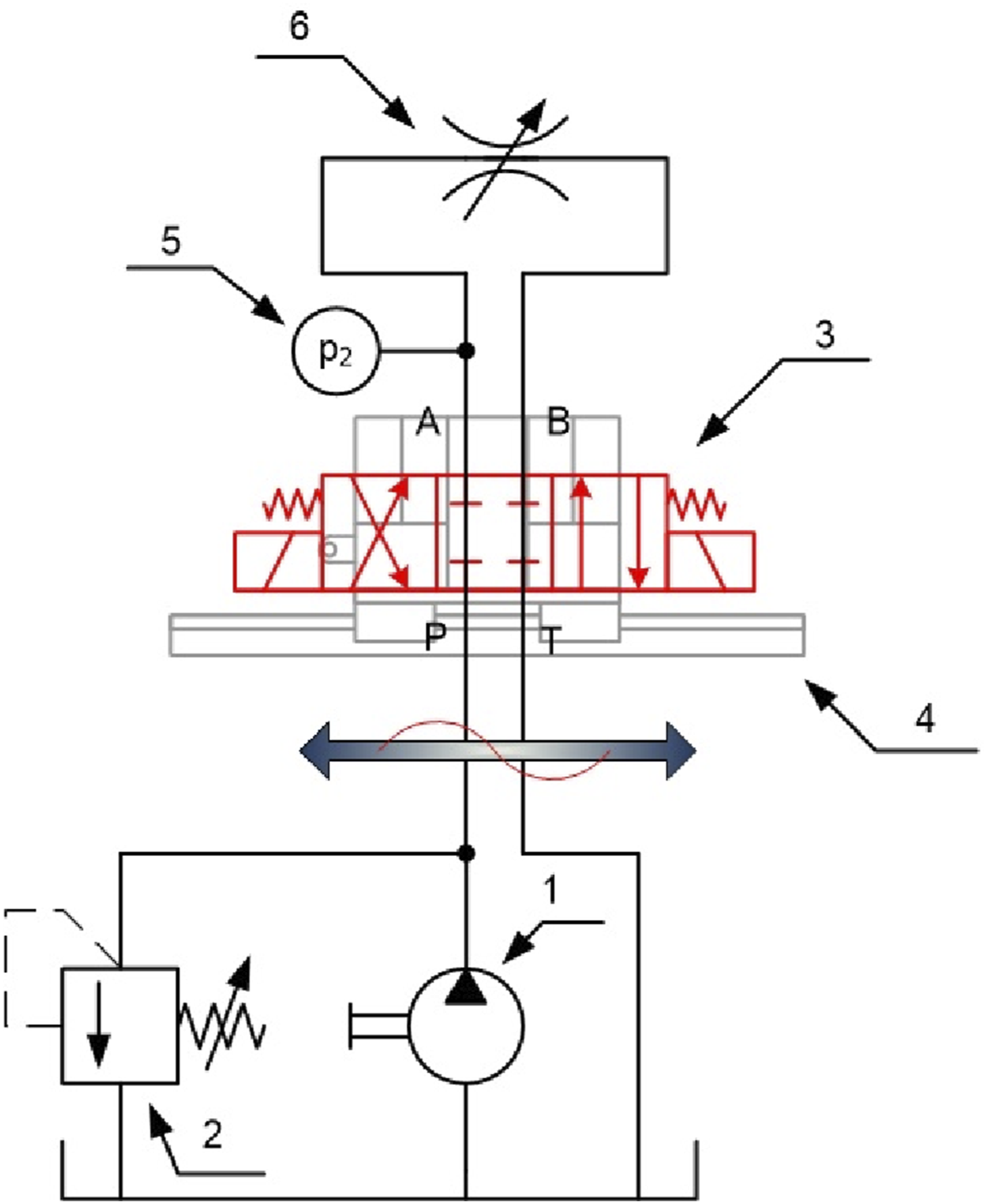
The flow balance equations, using the flow continuity principle, can be written as follows


Equations (13)–(15) form a system of equations which, after parameterization, can be solved numerically and time courses of spool displacement x, pressure p 1 in front of the vibrating directional control valve, and pressure p 2 behind the vibrating directional control valve can be determined.
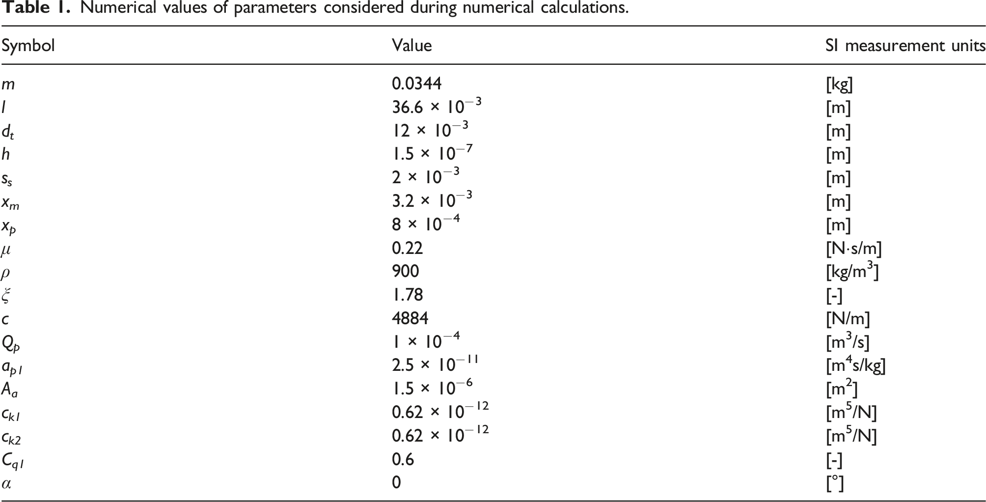
Numerical values of parameters considered during numerical calculations.
The external kinematic forcing is described by a harmonic function of the form given by equation (2). For the frequency f = 30 Hz: w
0
(30) = 0.14 × 10⁻³ m; for f = 40 Hz: w
0
(40) = 0.1 × 10⁻³ m; for f = 50 Hz: w
0
(50) = 0.11 × 10⁻³ m; for f = 60 Hz: w
0
(60) = 0.22 × 10⁻³ m. The solution is conveniently presented in the form of an amplitude–frequency spectrum of pressure pulsations at p
2
(shown in Figure 6) – presented in Figure 7. The amplitude–frequency spectrum of pressure pulsation (average pressure is 4 MPa) in a hydraulic system with a vibrating directional control valve with a frequency of: (a) 30 Hz; (b) 40 Hz; (c) 50 Hz; (d) 60 Hz.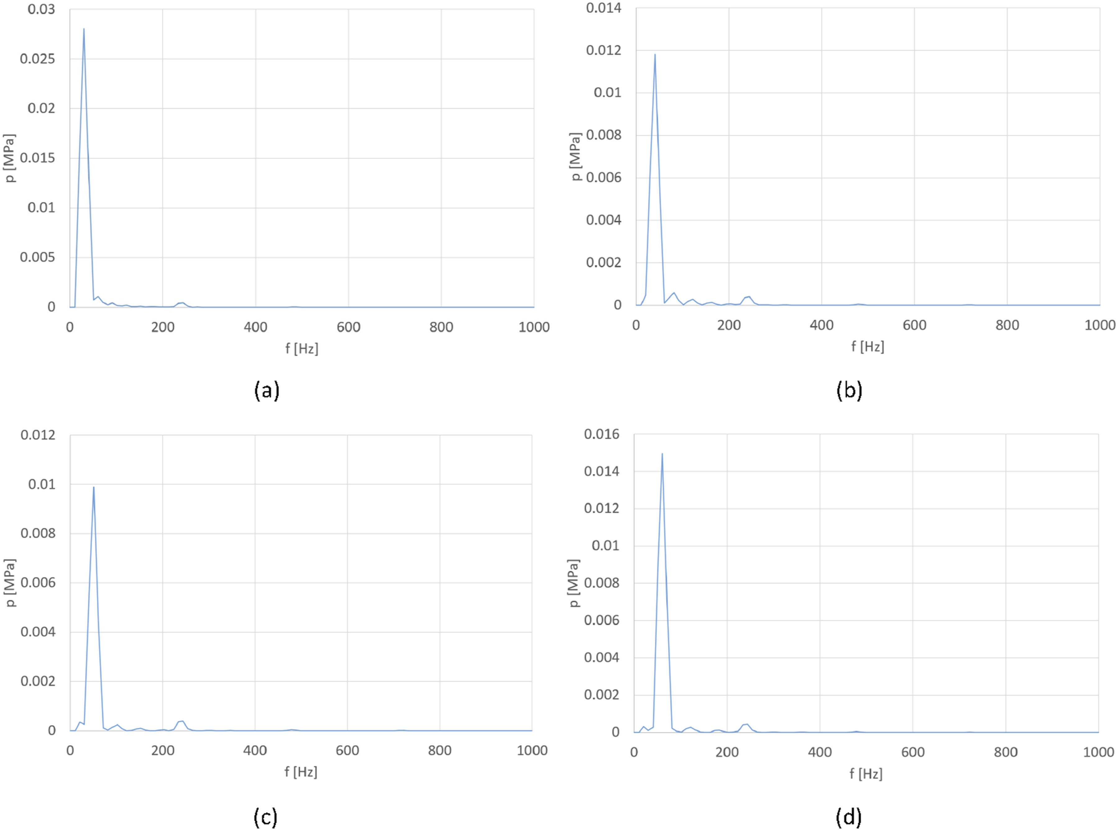
In Figure 7, the appearance of a harmonic component of the spectrum caused by forced vibration of the valve body can be observed. The frequency of this pulsation corresponds to the vibration frequency of the valve body.
Experimental studies of the influence of vibrations on the spectrum of pressure pulsations
In order to verify the correctness of the obtained simulation results, experimental tests were performed. A reciprocating hydraulic simulator was used to generate the vibrations acting on the valve. The main elements of the simulator were a hydraulic power pack with a gear pump, a servo valve, an actuator, a table with a holder in which the hydraulic directional control valve was mounted and a servo valve control system with specialized software. The simulator made it possible to generate mechanical vibrations with frequencies below 100 Hz. The tested directional control valve and simulator are shown in Figure 8. The test stand during testing of the influence of vibrations on the spectrum of pressure pulsations.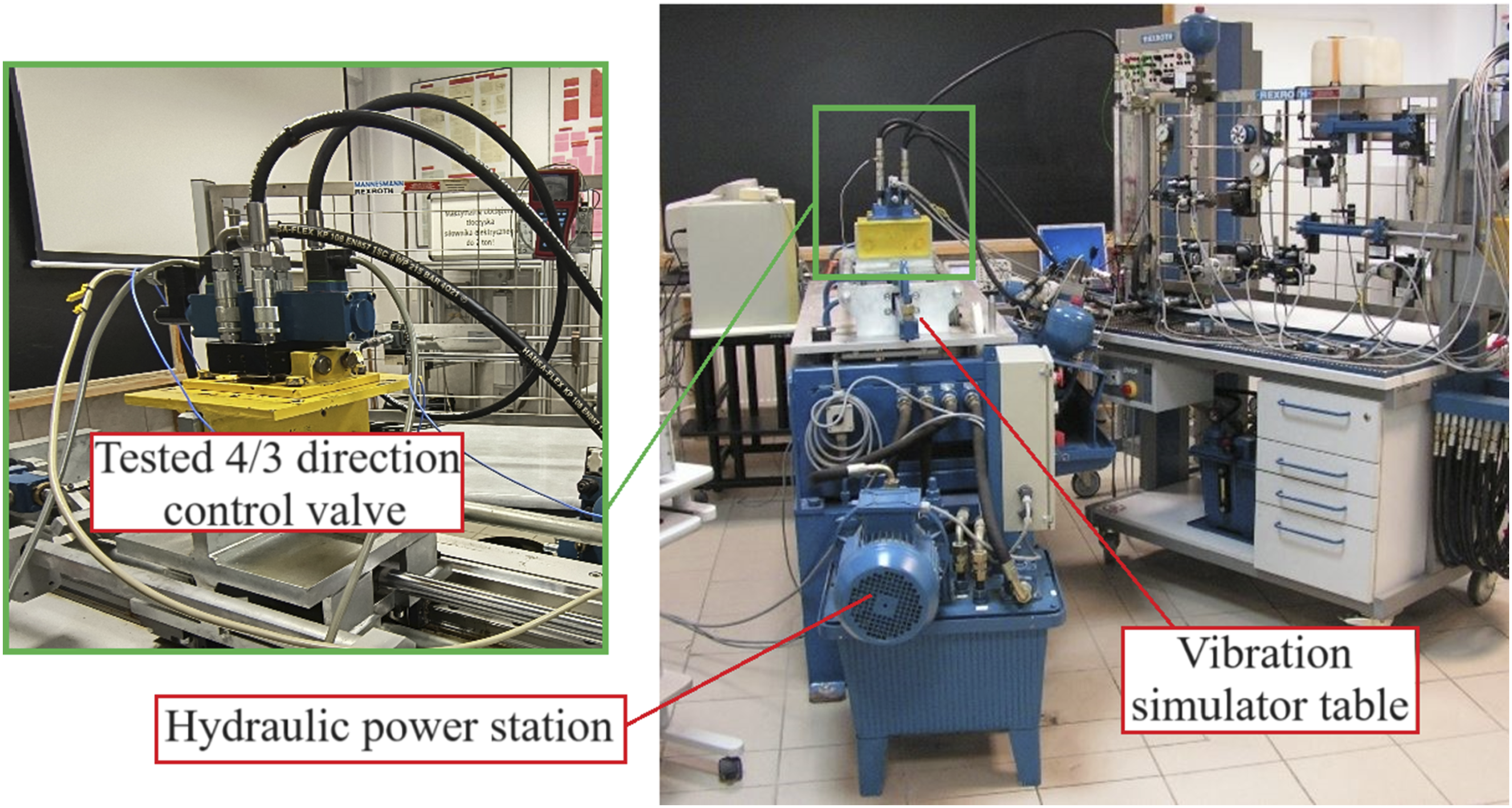
The tested directional control valve operated in a hydraulic system, the diagram of which is shown in Figure 6. During the tests, the directional control valve coil was supplied with 24 V DC, which caused the directional control valve slider to occupy an extreme position. Tests were carried out in which the vibrations acting on the valve body were the same as the direction of movement of the spool, so the angle α was assumed to be 0. During the tests, the following values were recorded: vibrations of the simulator table (a single-axis accelerometer), vibrations of the directional control valve body (a single-axis accelerometer), pressure pulsation at point p
2
(show in diagram Figure 6) (a piezoelectric miniature pressure sensor), the mean pressure in the system (a manometer). Figure 9 shows a schematic representation of the vibration and pressure pulsation measurement paths. Diagram on measurement circuits for mechanical vibrations acceleration and pressure pulsation: TO – tested object (directional control valve), AC1–356A02 Piezotronics accelerometer measuring the vibration of directional control valve body, PC1–ICP 105C23 Piezotronics pressure sensor measuring pressure pulsation in hydraulic system, SC—multichannel signal conditioner, DO – multichannel digital oscilloscope Tektronix TDS 224, PC—personal computer.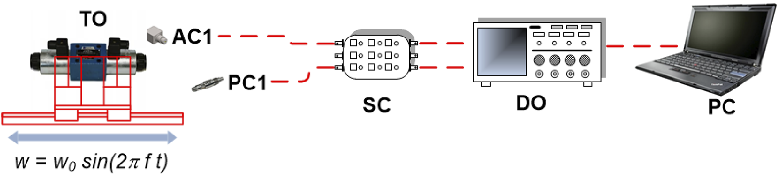
In Figure 10 shows spectra of pressure pulsations in a system with a vibrating directional control valve. Figure 10 additionally shows the value of the p
m
amplitude of the pressure pulsation obtained from the numerical considerations. The amplitude–frequency spectrum of pressure pulsation (average pressure is 4 MPa) in a hydraulic system with a vibrating directional control valve with a frequency of: (a) 30 Hz; (b) 40 Hz; (c) 50 Hz; (d) 60 Hz.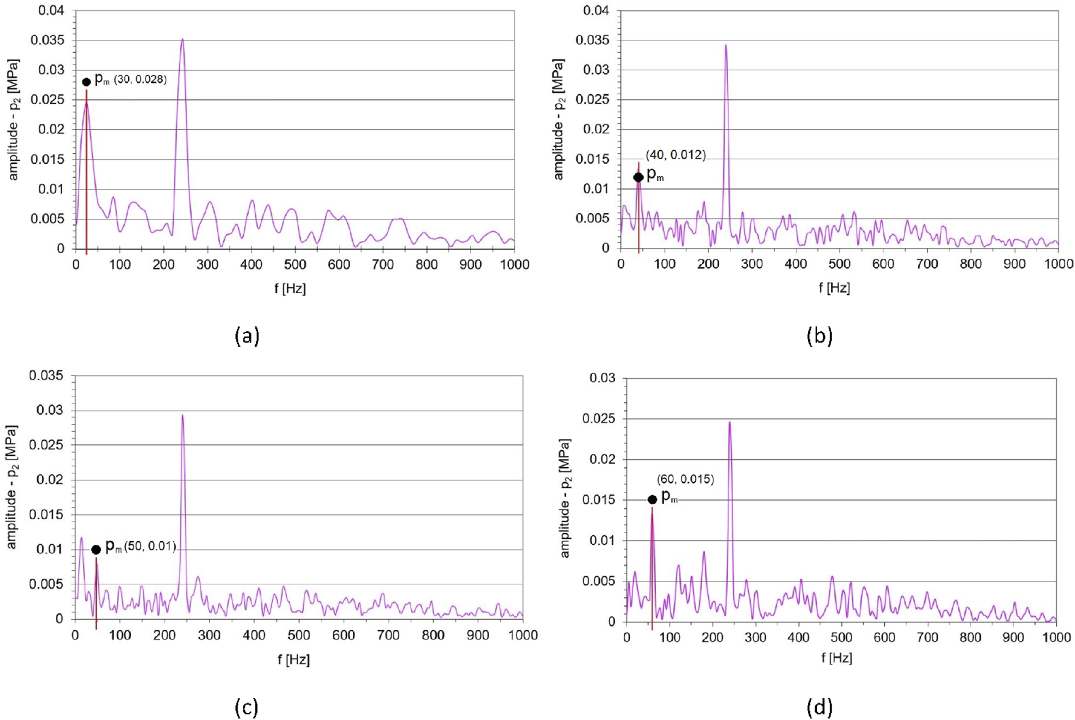
The spectra of pressure pulsations presented in Figure 10 show the spectrum component corresponding to the frequency of vibrations of the directional control valve body. In addition, a component with a frequency of 242 Hz can be noticed. The pulsation of pressure with such a frequency is caused by the pulsation of the pump’s efficiency supplying the tested directional control valve’s hydraulic system.


Uncertainties of measuring devices.

As measurement uncertainty for each device is different, the acceleration and pressure are a function of three variables. The total measurement uncertainty can be presented as follows

The relative uncertainty δa and δp will be described by equation

For the measuring apparatus used for the experiment, relative uncertainty of acceleration and pressure are equal to 5% and 4.9%, respectively.
Summary and comparison of pressure pulsation amplitudes for analyzed forcing frequencies.
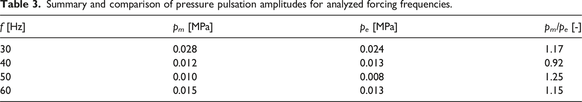
A comparison of the values of the pressure pulsation amplitudes contained in Table 3 shows that the differences between the values obtained by numerical simulations and by experimental testing are no greater than 25%. Furthermore, the largest differences are observed around the resonance frequency of the directional control valve spool, that is, around 50 Hz.
Evaluation of the impact of capacitance changes on the amplitude of pressure pulsations
The presented modified model of the vibrating directional control valve may be useful for assessing the influence of the system capacitance change on the pressure pulsation amplitude value caused by the directional control valve spool’s vibrating movement. Changing the system’s capacitance can be done in various ways, including by changing the susceptibility of the hydraulic pipes. The value used in the modeling (c k = 0.62 × 10⁻¹² m5/N) was adopted as the reference capacitance value. The change in capacitance was analyzed to the value of c 2k = 2·c k and c 3k = 0.5·c k .
In Figure 11 shows the effect of the capacitance change—the change in the value of the pressure pulsation amplitude caused by external mechanical vibrations. Effect of changing the system capacitance on the amplitude value of the harmonic component of the pressure pulsation for the valve body vibration frequency (f): (a) 30 Hz; (b) 40 Hz; (c) 50 Hz; (d) 60 Hz.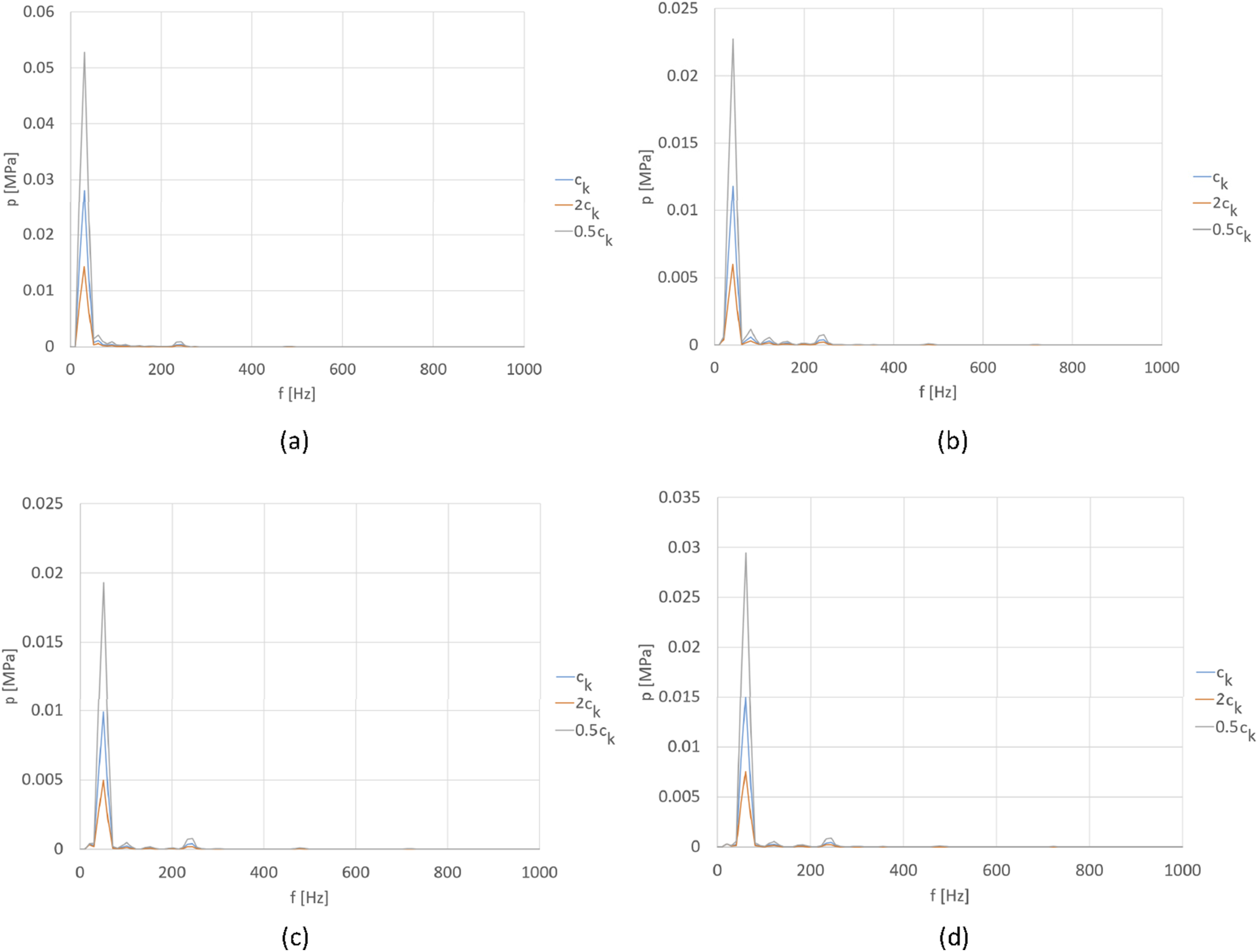
The spectra presented in Figure 11 indicate that by changing the capacitance of the hydraulic system, the value of the pressure pulsation amplitude can be influenced. It is observed that the reduction in the amplitude of the pressure pulsation for the selected frequency is due to an increase in the value of the capacitance. Reducing the capacitance increases the amplitude of the pressure pulsations. However, it should be noted that the increase in capacitance causes a decrease in the natural frequency of the hydraulic receiver, and the hydraulic system becomes “spongy.”
Discussion
On the basis of the presented results of analytical, simulation, and experimental considerations, the coincidence of external mechanical vibrations and changes in the pressure pulsation spectrum of a hydraulic system was indicated. This coincidence is relatively rarely indicated in the literature, and classical models of hydraulic valves do not take into account the occurrence of external mechanical vibrations. The mathematical model of the oscillating motion of the directional control valve spool presented in the paper takes into account external mechanical oscillations recorded as harmonic kinematic forcing. The oscillating movement of the slider causes additional harmonics to appear in the pressure pulsation spectrum. In the pressure pulsation spectrum, harmonic components can additionally be observed which originate from the pulsation of the displacement pump output. These components usually have higher frequencies. These harmonic components were not considered in the paper. In addition, the value of the pressure pulsation amplitudes is influenced by resonance phenomena in the hydraulic lines, which were also not considered in the paper. However, the proposed mathematical description can also be used to evaluate the effect of changing capacitance on pressure pulsation amplitudes. From the simulation plots provided, it can be seen that an increase in capacitance causes a decrease in pressure pulsation amplitudes. A change in capacitance can be obtained, for example, by changing the geometry of the hydraulic pipes, changing the working fluid, changing the equivalent bulk modulus or adding a hydro-accumulator. A change in capacitance also occurs as a result of a change in the volume of gas contained in the hydraulic oil. 27 An increase in the volume of gas contained in the hydraulic oil results in a decrease in bulk modulus and an increase in capacitance. 28 However, it is difficult to determine the exact gas content of the hydraulic oil under real conditions. Therefore, an equivalent bulk modulus is determined, which is a measure of the deformability of the system (oil and other deformable elements of the hydraulic system—mainly the flexible hoses).
Conclusions
The paper focuses on the problem of the effects of external mechanical vibrations acting on a single-stage hydraulic directional control valve controlled by “on/off” electromagnets. The case in which the spool of the directional control valve is switched to the extreme position by the electromagnet jumper was considered. The mathematical description of the vibrating movement of the directional control valve spool was modified, taking into account the kinematic excitation and the angle between the direction of this excitation and the direction of movement of the spool in the vibrating directional control valve body. Due to damping in the circumferential slots of the directional control valve and centering springs, the vibrating body induces the slider to vibrate. This causes a periodically variable value of the surface area of the choke gap formed by the slider and the directional control valve body. This means periodically variable throttling of the flowing liquid, which creates additional components in the pressure pulsation spectrum with frequencies equal to the frequencies of the vibrating valve body. The spool of the directional control valve can be treated as a single-mass system, and for such a system, the value of natural vibration frequency can be determined. Thus, the greatest impact of external mechanical vibrations will be for the frequency of these vibrations close to the spool’s natural frequency and the spool’s direction of movement in the valve body. As indicated in the paper, it is possible to influence the pressure pulsation amplitude’s value by changing the system’s capacitance value.
Footnotes
Declaration of conflicting interests
The author(s) declared no potential conflicts of interest with respect to the research, authorship, and/or publication of this article.
Funding
The author(s) received no financial support for the research, authorship, and/or publication of this article.