
Abstract
As friction is inherently nonlinear, simulating its dynamics in a system is never an easy process. The study suggests a novel friction model that mimics the stiction friction model using sigmoid and exponential functions. The friction force value at 0.01 m/s, or just 1% of the whole velocity range, is precisely provided by the suggested model. The model is found to be more appropriate for linearizing the friction force and is less complex than the comparable friction model that is currently available in literature. The accuracy of computer simulation in proposed friction modeling is contingent upon the value of the sigmoid index. The sigmoid index value of n = 5000 validates the accuracy of the modeling. The simulation results produced by the current LuGre friction model are used to validate the suggested model responses. To comprehend the qualitative and quantitative impact of system factors on its stick-slip behavior under friction, additional interventions are made to the suggested model. It is discovered that the damping ratio (ζ) has the least effect on sticking time, and the static friction to kinetic friction ratio (
Introduction
Currently, modeling is being used more and more to effectively characterize specific systems under friction. 1 The modeling of friction attracted the research community to adopt it for effective control by knowing system dynamics under friction. 2 This explores the need to create potent and applicable product models. Being nonlinear in nature, friction influences the dynamics of mechanical systems. All mechanical systems experience friction, which is a significant source of power loss, vibrations caused by friction, positioning errors, stick-slip, etc. 3 Therefore, in all simulations and analyses, it is crucial to accurately describe and forecast friction phenomena.4,5 It is always a challenging task to model the friction as a continuous function so that it can be used directly for the computer simulation. 6 Many models to understand the dynamics have been proposed in the literature; however, because of the nonlinearities involved, the models cannot be immediately applied to analysis, and solving differential equations becomes more complex. When it comes to design and development, friction is a worry, and accurate and efficient systems are made possible by properly modeling it.7,8 Both the macroscopic and microscopic behavior of asperities affect friction, and friction models should be able to handle pertinent similarities with less complexity. 9 Models are static without frictional memories and dynamic with friction memories. 10 Several Static models have been proposed in literature. 11 The Stribeck model 12 can also be considered to belong to the set of models. In Coulomb friction model there is infinite value of friction force at zero crossing. 13 Karnopp 14 presented a solution to the issue at the zero crossing. He avoided the switching between differential equation for sticking and sliding. A more general model 15 has considered practically all static friction phenomena, including stiction, coulomb, viscous, and Stribeck friction. The contact asperities always have limited stiffness by virtue of which small linear displacement takes place under the application of force in static region known as presliding displacement or Dahl effect. 16
The motion of a spring pendulum with two degrees of freedom that is harmonically damped on an elliptic trajectory is studied dynamically. The compliance of presliding displacement mitigates the sharp nonlinearity of friction at zero velocity. Presliding displacement only happens when applied force is lower than static friction. 17 The delayed response of the friction force to a change in velocity is known as frictional lag. It affects the system dynamics very significantly and causes a higher friction force for increasing velocity. 18 Stick-slip is described as the sequential arrest of motion between two surfaces where sequentially sticking followed slipping of surfaces. The motion is governed by friction at two different phases of at motion and arrest it happens at low velocities.19,20 Stick-slip creates serious nuisance and tends to malfunction of the system especially in control applications. The foundation for dynamic friction models was established by the previously mentioned dynamic friction phenomena. A few dynamic friction models, beginning with the Dahl model, have been proposed recently. 21 The control community has put forth a few friction models and sought to gain additional understanding of the dynamic model.22–25 These models nowadays are used extensively to simulate system dynamics. Almost all the friction phenomena are reported by LuGre friction model. 22 Dahl transformed the stress-strain curve to displacement curve. The random behavior of friction has a direct relationship with the random distribution of asperities, and this became the starting point for the bristle by Haessig et al. 23 The viscous friction model results from the lubrication of contacts in the majority of engineering applications. Harnoy and Friedland have presented a model of using hydrodynamics.
26 The research stated that the eccentricity of bearing is very important in deciding the friction force for lubricated surfaces. Bliman-Sorine friction model 24 is inspired by the Dahl model and differentiated the fast Dahl model and slow Dahl Model to explain the stiction. It has been shown by a comparative study27,28 that the LuGre model is beneficial since it includes almost all the friction phenomena except hysteresis which later taken care of Leuven model. 29 Dupont et al. 30 also criticized the LuGre model by correlating the drift phenomenon with characterizing the applied force by small vibrations. A new friction model by parallelization of original LuGre model has been incepted and it has been given a name M-LuGre model. 31 Alice Berardo and Nicola M. Pugno 32 proposed a friction model correlating friction of structures by hierarchical surfaces. They considered the surfaces with 1D and 2D roughness and concluded that the frictional behavior of rubbing surfaces depends on wear and the direction of sliding. Rilian Shao et al. 33 proposed a model for rubber on rigid surface. To determine if systems with rubbing surfaces work as intended, proper friction modeling is essential. 34 One of the key phenomena in control applications is stick-slip motion. 35 To determine the instability speed and critical stick-slip speed, this process is examined in a number of experimental studies and analyses. 36 Therefore, stick-slip behavior should be examined in detail. The degree to which stick-slip behavior is impacted by changes in steady-state friction with increasing velocity depends on how rigid the system is. 37 Systems with low velocities and high velocities should handle stick-slip behavior differently. 38 The change from stick-slip to slip motion occurs at a specific driving velocity and friction. 39 By adjusting a piston’s rotational velocity, stick-slip can be avoided. 40 The stick-slip can be eliminated from the system at a greater level of driving velocities. 41 The history of motion and velocity feedback work together to govern the stick-slip. 42 By carefully choosing the right mix of a linear controller and feedback-based compensating friction, stick-slip can be decreased. 43 Iron oxides migrate from the steel surface to the sealing surface, increasing the Fs/Fc ratio and extending the sticking period. 44 Selecting the appropriate damping coefficient for a system will eliminate stick-slip. 45 Nonlinear 2D and 3D systems’ modeling is a complex process that requires accurate friction dynamics description.46,47 Thus, accurate mathematical modeling that guarantees a sufficient degree of dynamic stability is essential for regulated dynamic behavior of the systems.48,49
Many of the friction models proposed in literature are discontinuous and need piece wise integration which is objectionable in control applications. The convention numerical methods applicable to linear system would not be suitable for the dynamics of a system with friction. Hence efforts should be made to establish a smooth relationship between friction force and velocity. The aim of the present work is to make a linear stiction friction model that can circumvent the nonlinearity at the velocity reversal viz. zero velocity crossing. To capture the system science under friction, a new stiction friction modeling with the aid of sigmoid and exponential function is studied in this article. The results of simulation utilizing the stiction model, which is based on sigmoid and exponential functions, are consistent with those of other comparable models in literature. 50 The response from the LuGre model is used to validate the results from the sigmoid and exponential functions for a particular spring-mass-damper system.
The objective of present work is: a. To simulate the friction caused by stiction using sigmoid and logarithmic functions as a continuous function of velocity. b. To investigate the qualitative and quantitative effects of the influencing factors on the stick-slip induced vibration.
The originality of this work is found in its goals, which are distinctive. The model’s processing treats each parameter individually to account for how it affects stick-slip. The novelty of the work is the faster dynamic responses in computer simulation and the correlation between the sticking time and other influencing parameters.
Mathematical modeling of stiction friction
For researchers, simulating friction in dynamic systems has always been a difficult issue. Nonlinearities resulting from the direction of the friction force changing at the time of velocity switching are present in both the classical Coulomb model and the stiction model. The conventional approaches applied to linear systems cannot be used to analyze dynamic systems and control systems, which are defined by discontinuous friction force. The optimum approach for such a system is to use numerical approaches with computer-assisted iterative calculation. As a result, the stiction model is represented in the current study using a combination of the sigmoid function and the exponential function, respectively. Jitendra yadav et al. 28 have proposed the modeling of classical Coulomb model with the help of sigmoid function. The present work is the extension of the work.
The two main operating regimes covered by friction models are static friction at stagnation and Coulomb friction during motion. Surfaces in motion produce kinetic force or Coulomb friction, which is always smaller than the friction produced by surfaces at rest. Starting the relative motion between the surfaces from a still state requires an external force greater than the force of stiction. Kinetic or Coulomb friction, which persists between the surfaces during motion and causes it to be intermittent, causes stick-slip motion. Equation (1) also describes the velocity and the external force (

The external force determines the friction force for zero crossing. Since there are many values of friction force ranging between – Diagrammatic representation of stiction model.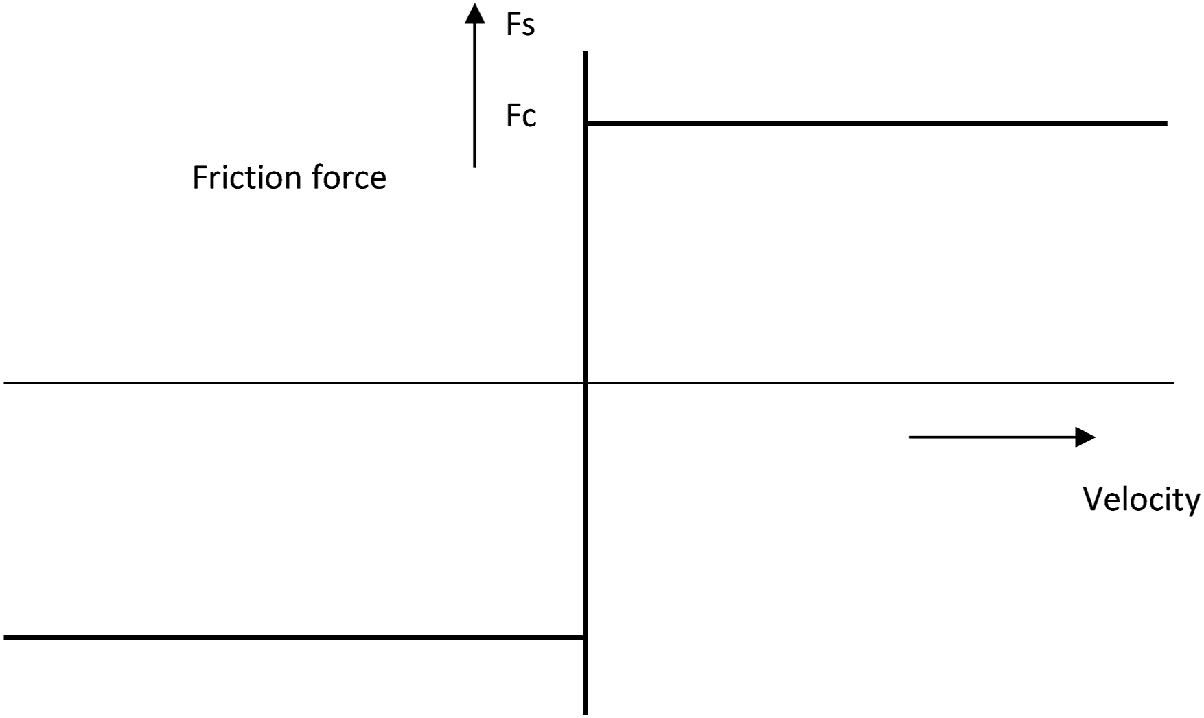
The terminologies used in this context are static friction (

Diagrammatic representation of the friction force in equation (2) is shown in Figure 2. For this the equation, parameters taken are m = 1 kg, Sigmoid + exponential function-based friction model.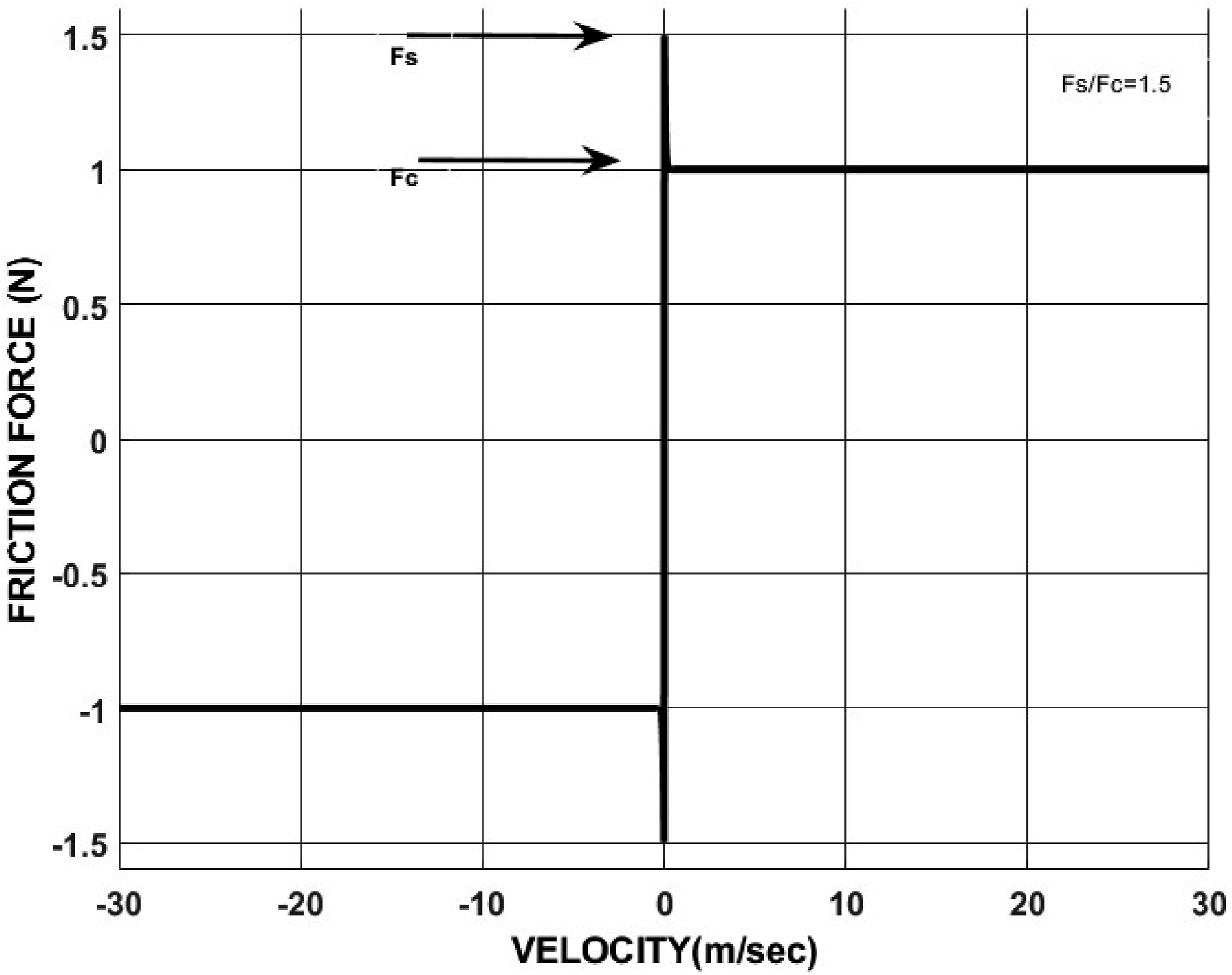
However, this representation is confined to a specific velocity range considering the velocity reversal into account, and the range can be stretched to any value without any modification in computer programming. With the value of index n = 5000, the curves are comparable with stiction model, and it can be directly used for computer simulation as the representation of stiction model. This makes possible the continuous integration of the entire range of solutions. The proposed stiction model curves give exact friction force value at velocity 0.01 m/s which is 1 % of entire range of velocity. By increasing the value of sigmoid index ever better approximation can be obtained, but at the cost of computational time. The modeling is simple in approach and the desired value of Variation of Fs/Fc with constant “a.”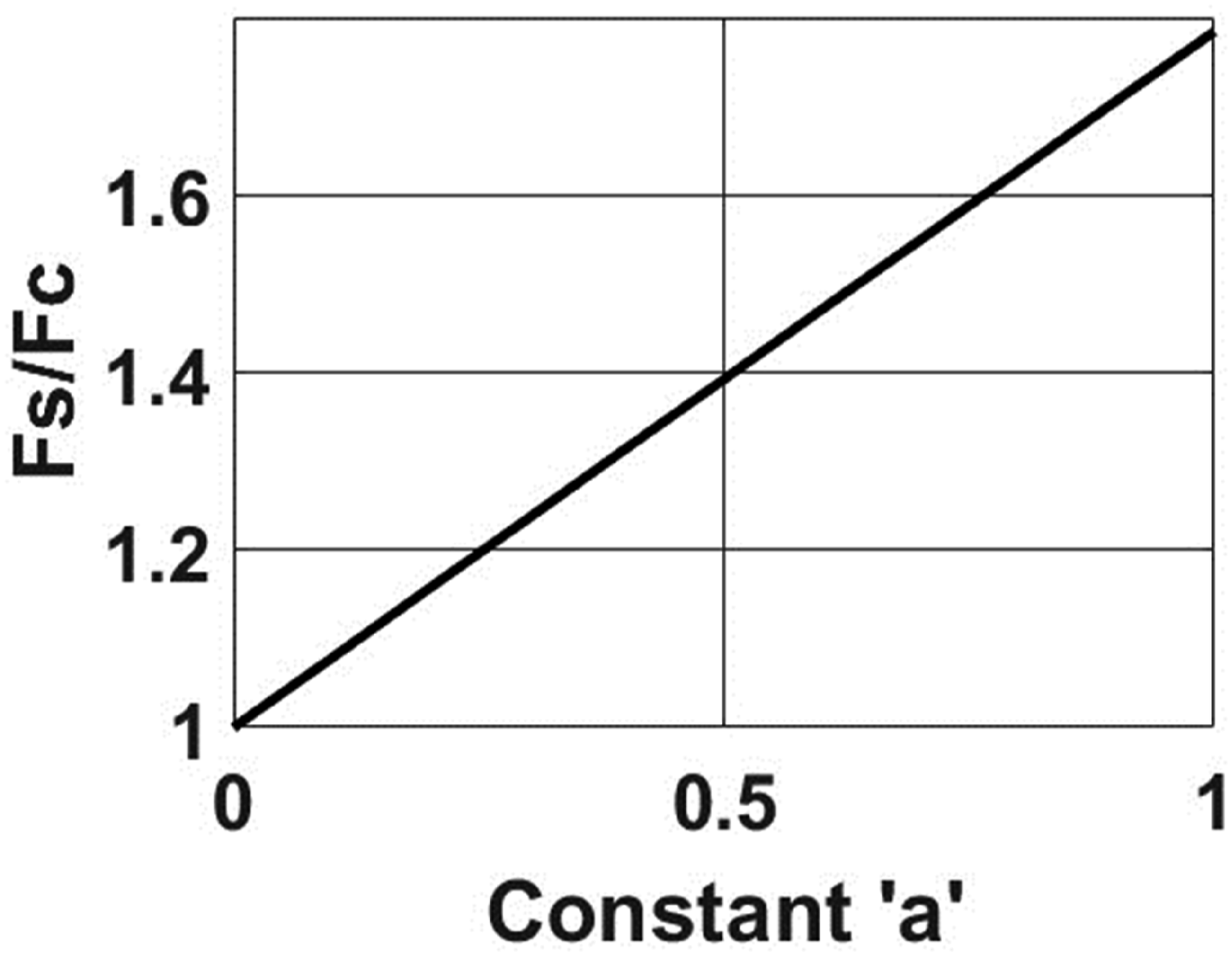
The exponential index “p” controls the shape of portion of the curve between
The model is simple and has lesser parameters to be controlled and solely captures the stiction model. It is a new approach and earlier no research work is found in the literature to capture the stiction model to have an insight of stick-slip induced vibrations. However, the model is limited to stiction friction only hence applicable to only dry friction condition. Incorporation of hysteresis effects is the potential area of improvement.
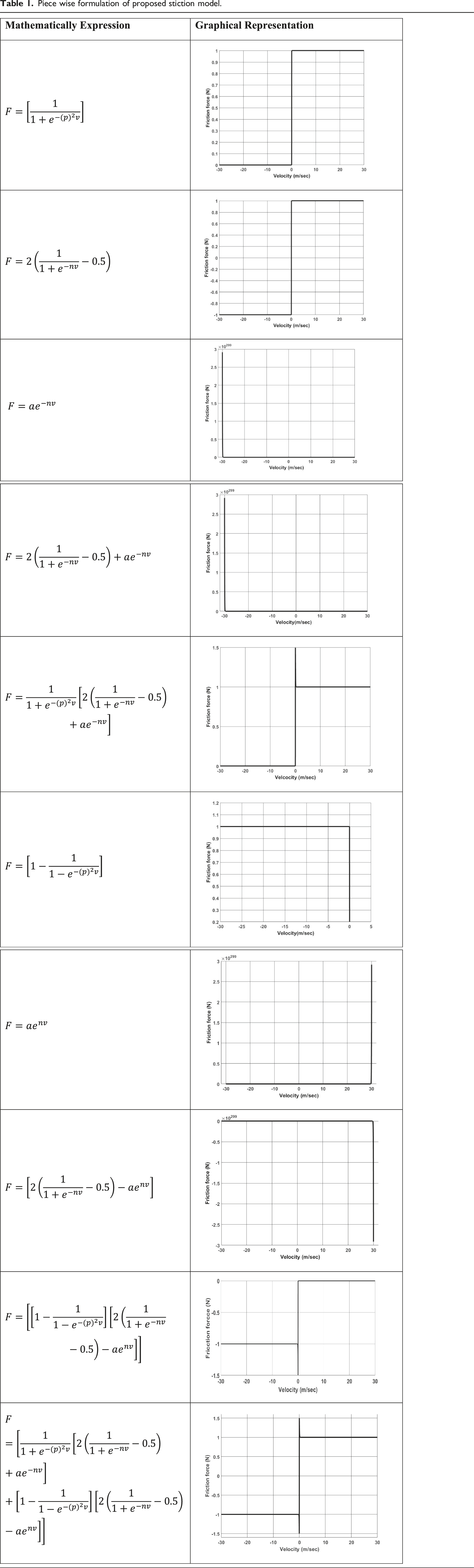
Explanation of piece wise formulation of the proposed stiction model
Piece wise formulation of proposed stiction model.
System modeling
The two major causes of stick-slip vibration are the inertial mass and the stiffness present in the system. To understand the system response of the proposed model and to validate the responses, a system as shown in Figure 4 has been taken comprising a spring-mass-damper that is driven over a rough surface at a constant speed. The mathematical representation defining the motion is depicted by equation (3) on the basis of absolute motion of the mass. Spring-mass-damper system.
Results and verification
Sample result
The issue is expressed formally as a second-order nonlinear differential equation that is not amenable to an accurate solution. For this reason, certain techniques like the Runge-Kutta formula must be applied to solve the equation. These techniques take a lot of time and effort. In other words, computer simulation solves the problem. It is suggested that ordinary differential equations be used for simulation. A computer solver is proposed to solve mathematical equations. To ensure accuracy, this solver employs automatic step-size control. Fixed step integration is not used. The solver interpolates its own solution as effectively as possible without sacrificing the precision of the solution to gather the answer at the required location. The Runge-Kutta formula provides the explicit foundation of this function. The formulation is the primary distinction between implicit and explicit integration techniques. Explicit systems define the current states by drawing on the past. Implicit schemes, on the other hand, define the present states based on both past and present states. As an explicit solver, the Runge-Kutta technique was used due to its correctness and efficiency. The tool used for numerically solving ordinary differential equations is MATLAB ode45 function. It belongs to the ODE suite, which contains various additional solvers such as ode23, ode113, and more. Nevertheless, one of the most widely used and adaptable solvers is ode45.
The system dynamics of the selected system as in Figure 4 are obtained by solving the governing equation (3), by using the proposed stiction model which is based on sigmoid and exponential function by computer simulation. The sample result in terms of response of the system in form of displacement, velocity and friction force v/s time plots is shown in Figure 5. The responses capture the facets of system dynamics under stiction friction viz. the stick-slip motion, which is attributed by freezing time (time taken to start the motion), sticking time (arresting of mass over the surface), velocity peak, and frequency. These findings will enable the engineers to select and optimize the influencing parameters at the design stage itself. Response of the system under the proposed modeling of friction for m = 1 kg, k = 2 N/m, 
Validation of proposed stiction friction model by results of the LuGre model
The complete LuGre model of dynamic friction is described mathematically by equation (4) to equation (7).
2


Therefore,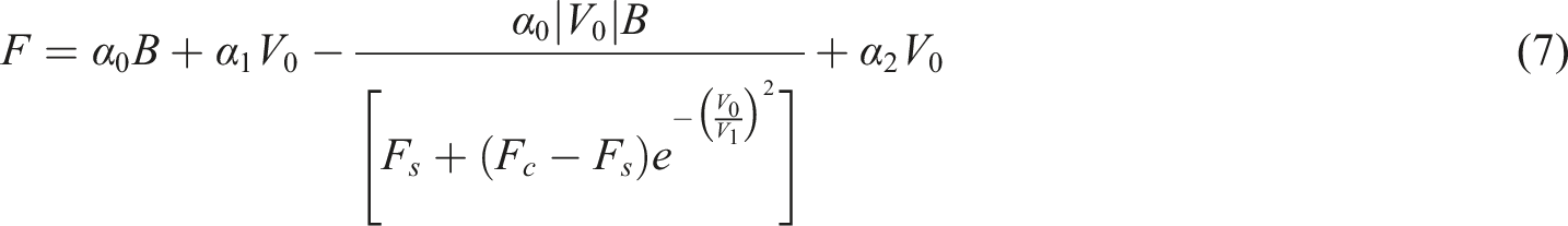
where,
B stands for lateral bristle displacement,
The LuGre model is a well-developed dynamic friction model and captures almost all the friction phenomena, that is, presliding displacement, break away forces, stick-slip, and Stribeck effect and only lacks in explaining the hysteresis effect. The model itself consists of damping in terms of the parameters
Parameters for sample results for the LuGre model.
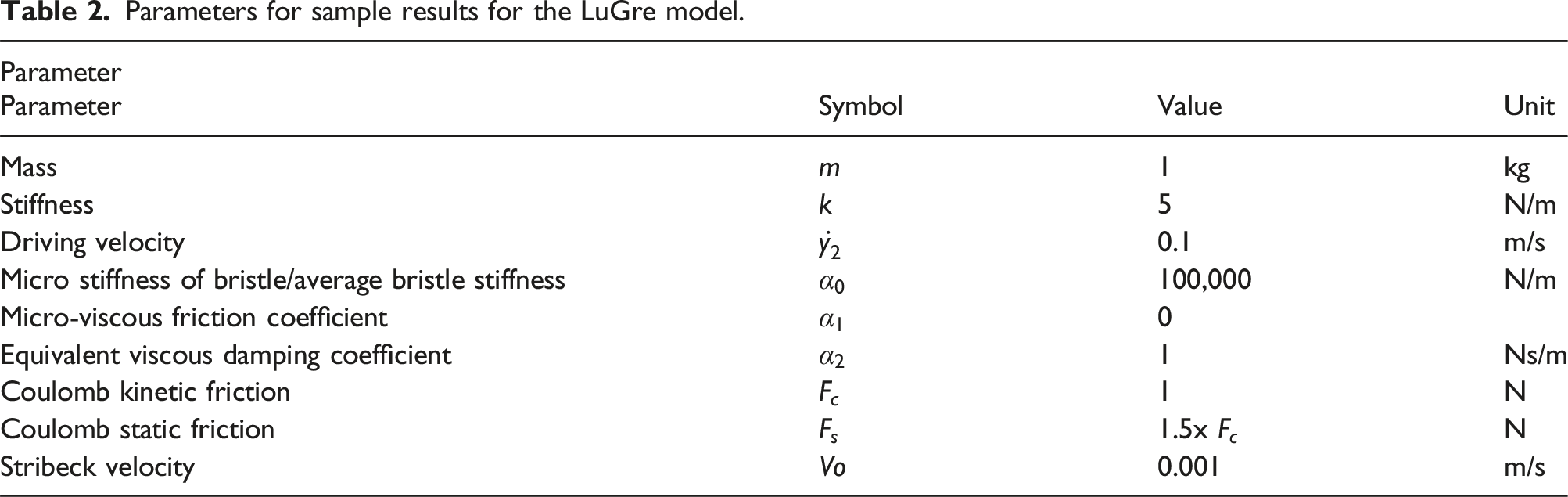
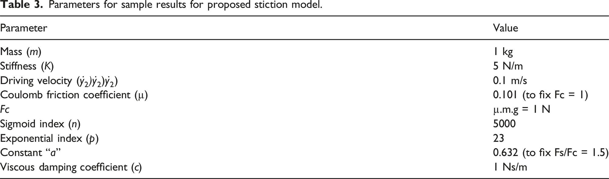
Figure 6 shows the comparison of results for the proposed model and the LuGre model. The system’s reaction to the proposed stiction model is obtained by computer simulation by solving the governing equation (3). The system and model attributes are shown in Table 3. Displacement and velocity v/s time plot. Parameters for sample results for proposed stiction model.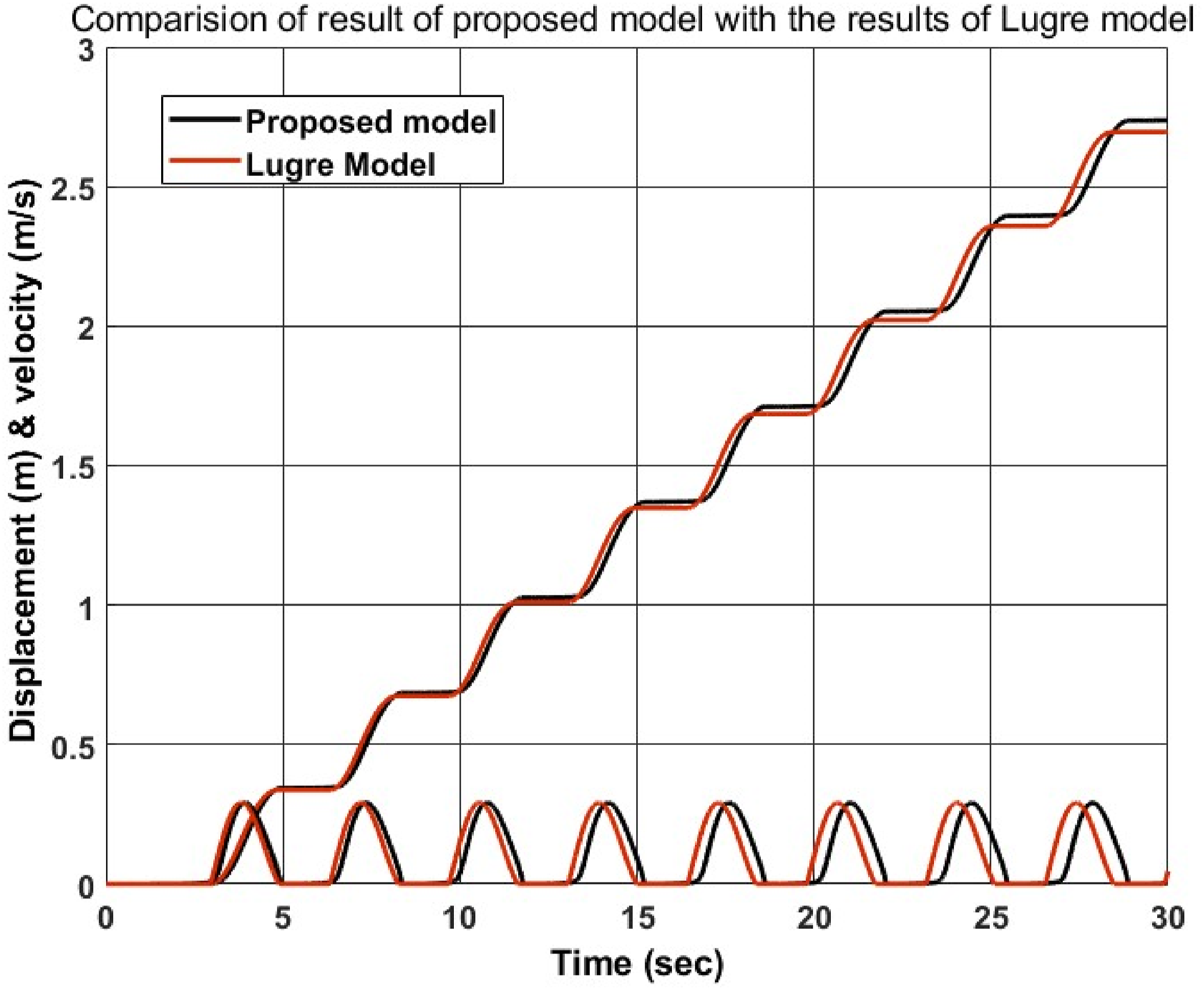
From Figure 6, it can be concluded that that the results of proposed stiction model are completely consistent with the findings of the LuGre model for the same system parameters and model parameters.
The LuGre model considered the viscous damping integral with friction force in for of
The above comparison is made to confirm the trends of the responses of proposed stiction model to validate it. As a result, the proposed model presented here is verified, and its use in simulation is justifiable.
Error analysis.
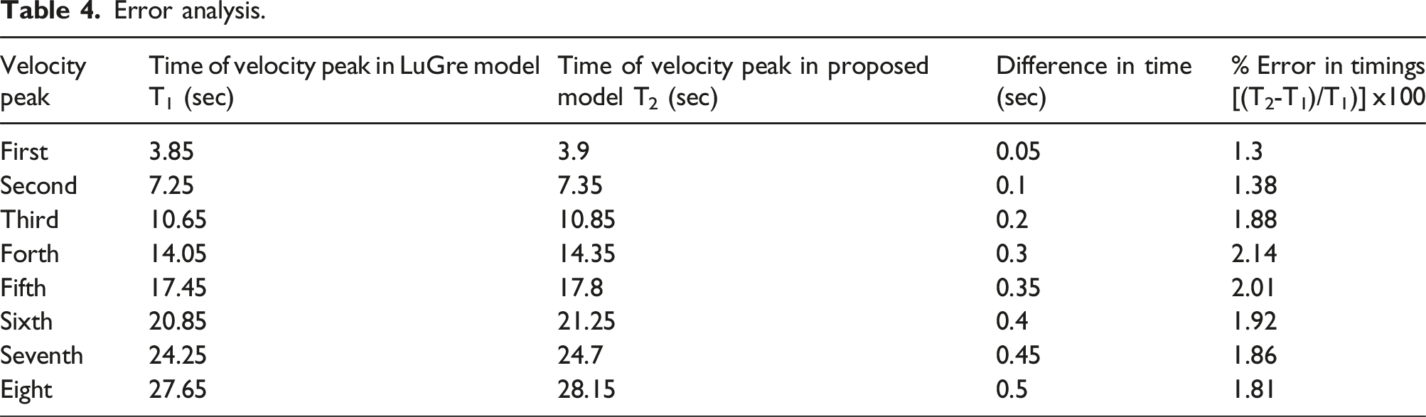
The table shows that the error percentage is consistently less than 5%, confirming the suggested model’s compatibility. By using the pattern of T1, T2, and the difference between these two, one can quickly compute the error for longer run times and confirm that the error percentage will always be less than 5%. However, real testing for various application situations or settings is required in order to evaluate the suggested model’s performance quantitatively to that of existing models.
Correlation for sticking time
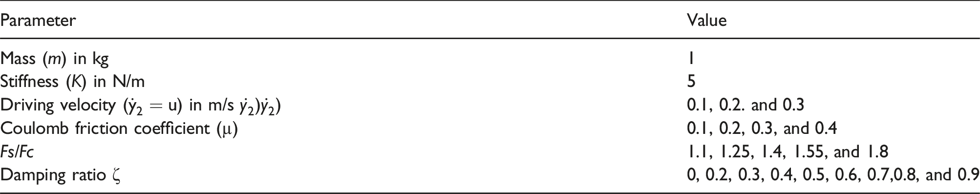
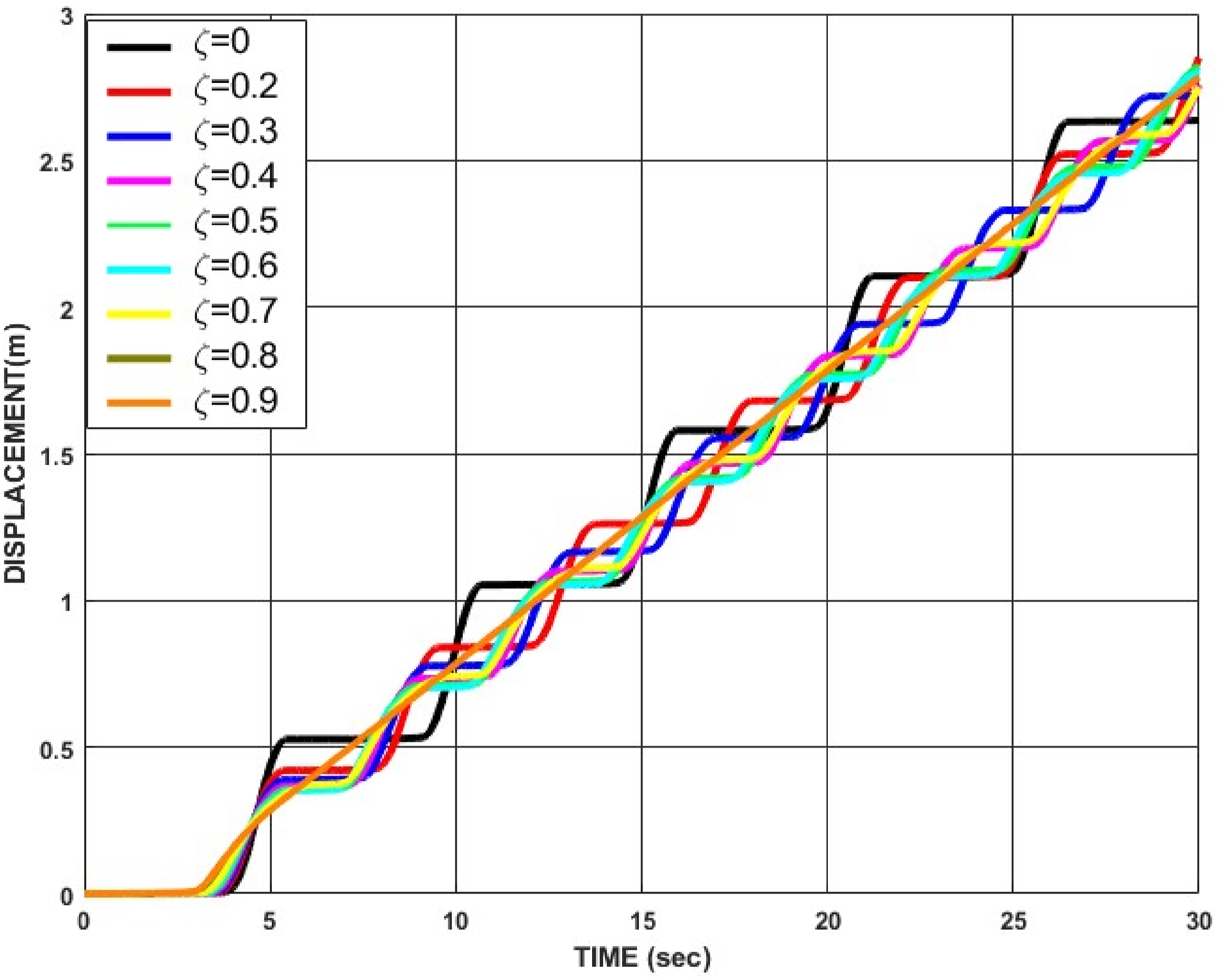
Displacement v/s time plot for different values of damping ratio for proposed stiction model for u = 0.1 m/s, Fs/Fc = 1.55, and µ = 0.1.
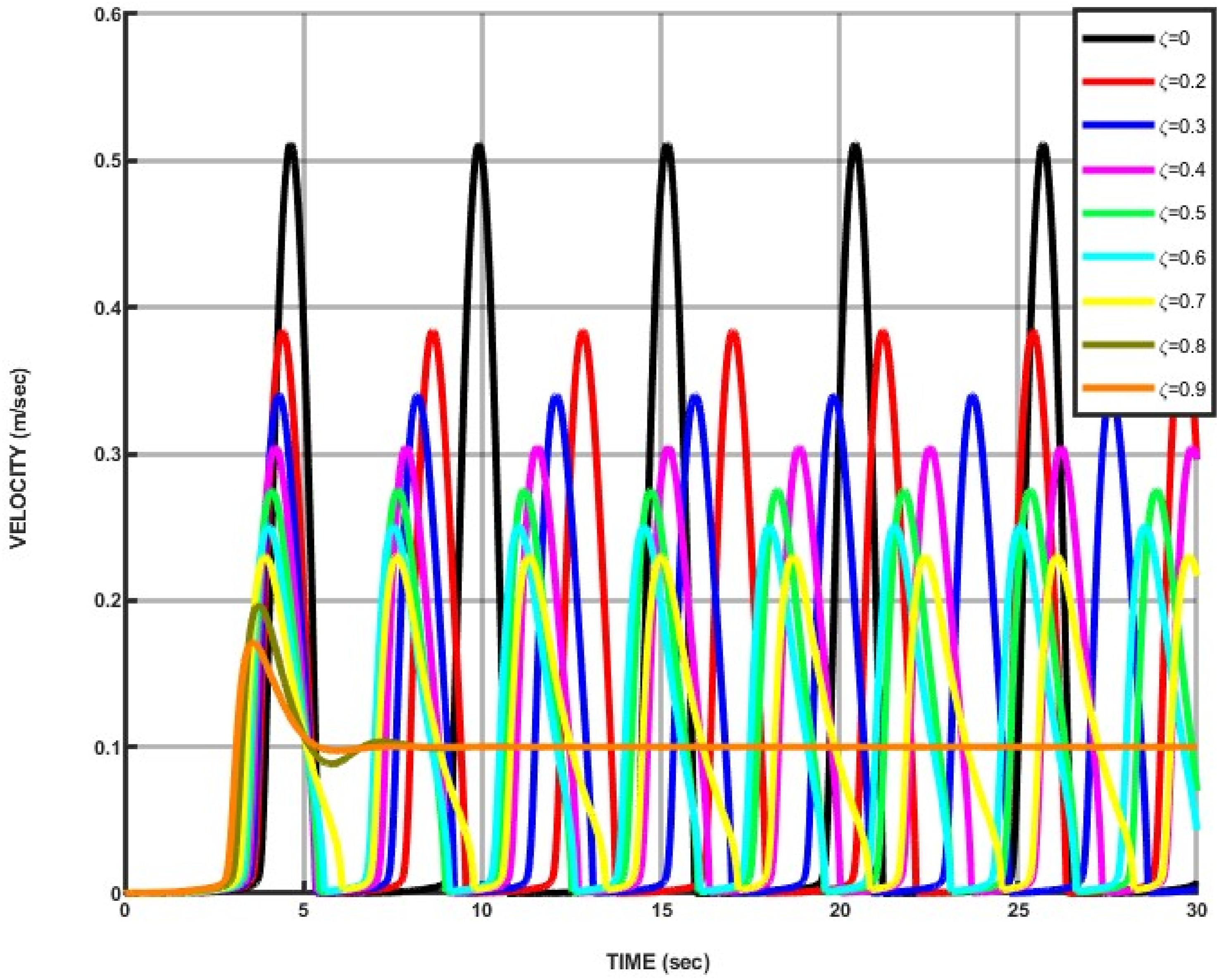
Velocity v/s time plot for different values of damping ratio for proposed stiction model for u = 0.1 m/s, Fs/Fc = 1.55, and µ = 0.1.
Sticking time for various values of damping ratio for Fs/Fc = 1.8, u = 0.1 m/sec, and µ = 0.1.
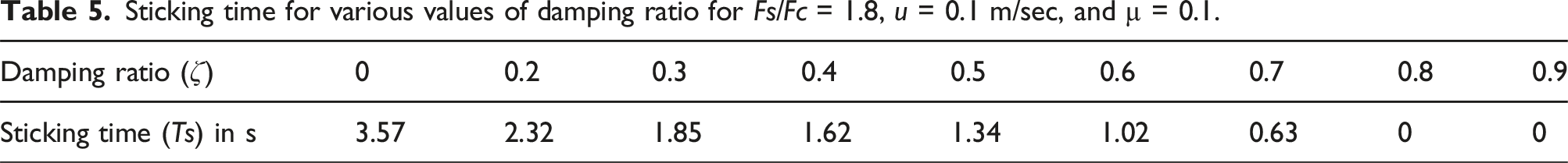
From the results, it has been concluded that the sticking time (
It can be observed that the coefficient of friction (µ) and the static to kinetic friction ratio ( a) Surface abrasion can be reduced by smoothing down the surfaces. b) By using the right materials in the right combinations between the rubbing surfaces, the static friction to kinetic friction ratio ( c) The system should be built to operate at a faster speed. d) Use of the system’s suitable damping.
It is also clear from the equation that
Conclusions
The goal of this work is to create a new friction model. The discontinuities at the velocity reversals that the classical Coulomb friction model and its derivatives encounter can be eliminated by using sigmoid function and exponential function-based modeling of friction. The value of sigmoid index n = 5000 is decisive in getting the exact Fs/Fc ratio and exact friction force value at velocity 0.01 m/s which is 1 % of entire range of velocity. The suggested model has been validated through past literature by comparing it with the existing LuGre model. The proposed friction models have got many merits over the LuGre friction model such as having fewer parameters, less computational time ensuring effective and prompt control, and flexibility of treating parameters at individual levels. The model can treat individual influencing parameters to eliminate and control the sticking time thus the stick-slip induced vibration. It is found that Fs/Fc ratio has the highest positive impact on sticking time with a power of 4.76 and driving velocity has a worst influence on sticking time with a power of −1.69. The extension of work is to generalize the stick-slip behavior by considering the range of mass and stiffness of the systems and practical use of the model for real time scenarios.
Footnotes
Author contributions
Conceptualization: JY, RK, AK, BG, LR, and SS; methodology: JY, RK, AK, BG, LR, and SS; formal analysis: JY, RK, AK, BG, LR, and SS; investigation: JY, RK, AK, BG, LR, and SS; writing—original draft preparation: JY, RK, AK, BG, LR, and SS; writing—review and editing: SS, KS, RK, SR, and KR; supervision: SS, KS, RK, SR, and KR; project administration: SS, KS, RK, SR, and KR; and funding acquisition: SS, KS, RK, SR, and KR. All authors have read and agreed to the published version of the manuscript.
Declaration of conflicting interests
The author(s) declared no potential conflicts of interest with respect to the research, authorship, and/or publication of this article.
Funding
The author(s) received no financial support for the research, authorship, and/or publication of this article.
Consent to publish
All authors have read and approved this manuscript.
Data availability statement
My manuscript has no associate data.