
Abstract
Considering the intricate design of the conventional inerter structures, the compressive-torsional coupling effects of chiral metamaterial are used to achieve the torsional movement alongside linear movement, forming a simplified inerter mechanism. This simplified design is then integrated with the nonlinear energy sink (NES). In this study, a novel NES with the chiral metamaterial inerter structure is suggested to mitigate vibrations in the cantilever beam system. The introduction includes both the piecewise linear beam, providing nonlinear stiffness, and the chiral metamaterial inerter structure. These components are combined to form the piecewise nonlinear NES with inerter (PNESI) structure. Subsequently, the PNESI structure is integrated with the cantilever beam system, and a corresponding dynamic model is formulated to evaluate its vibration mitigation capabilities. The theoretical results are verified through experiments. The findings indicate that under steady-state vibration conditions, PNESI achieves peak vibration reductions of 88.6% in simulations and 62.7% in experiments for the cantilever beam system.
Keywords
Introduction
A dynamic vibration absorber (DVA) is an additional mass structure coupled to a primary system with the aim of mitigating undesired vibrations.1,2 It is widely employed in aviation, automotive, and railway engineering for its straightforward design and dependable performance.3,4 The exploration of DVAs has progressed for over a century since Frahm’s initial proposal of a DVA without damping, resulting in the development of numerous highly efficient devices.5–7 However, compared to DVAs, NES demonstrates superior attenuation and absorption of vibration energy within the vibration system.8,9
NESs, passive vibration control devices, are pivotal in attenuating vibrations within mechanical systems. 10 By incorporating nonlinear elements, NESs generate nonlinear restoring forces, effectively absorbing and dissipating the energy of the primary system, thus mitigating undesirable vibrations. Significant research efforts have focused on the design and enhancement of NES, spanning a wide array of types including track NES,11,12 magnet NES, 13 vibro-impact type NES,14,15 non-smooth stiffness NES,16–18 lever type NES,19–21 and others. Among the various forms, the 2DOF NES has garnered significant attention and research owing to its dynamic complexity and the potential for extensive vibration suppression. Grinberg et al. 22 evaluated the vibration suppression capabilities of the 2DOF NES and discovered that the inclusion of additional degree of freedom substantially expands the range of amplitude reduction.
In recent years, inerter-based devices have gained increasing popularity for effectively mitigating undesirable vibrations in both machinery and structural systems.23–26 The concept of “inertial capacity” is initially introduced by Smith, 27 who highlighted its potential application in vibration suppression. Inertial capacity technology enables the reduction of the overall mass of the NES, resulting in a more lightweight design structure. Shen et al. 28 introduced an innovative fluid inertial capacity device, which exhibited remarkable capabilities in reducing vibrations. Brzeski et al. 29 achieved adjustability in the mass damper through the application of inertial capacity technology, and the performance of the adjustable mass damper is verified. Barredo et al. 30 present a pioneering DVA that utilizes negative-stiffness inerter structure, which demonstrated a high degree of effectiveness in suppressing vibration. The inerter can supply inertial properties significantly greater than its own mass, thus reducing the required system mass. However, traditional inertial capacity technologies are characterized by complex structures, large sizes, and challenging assembly processes. Chen et al. 31 propose an inerter structure that incorporates the intricate movement of a plunger within a cylinder, which in turn drives the flywheel through the frame, pinions, and gears. The inerter structure designed by Hu et al. 32 comprises two main components: main body of the flywheel and the lower part of the collar. In Refs,33–35 the proposed inerter structure is relatively complex, highlighting the need for attention to simplifying inerter in design considerations.
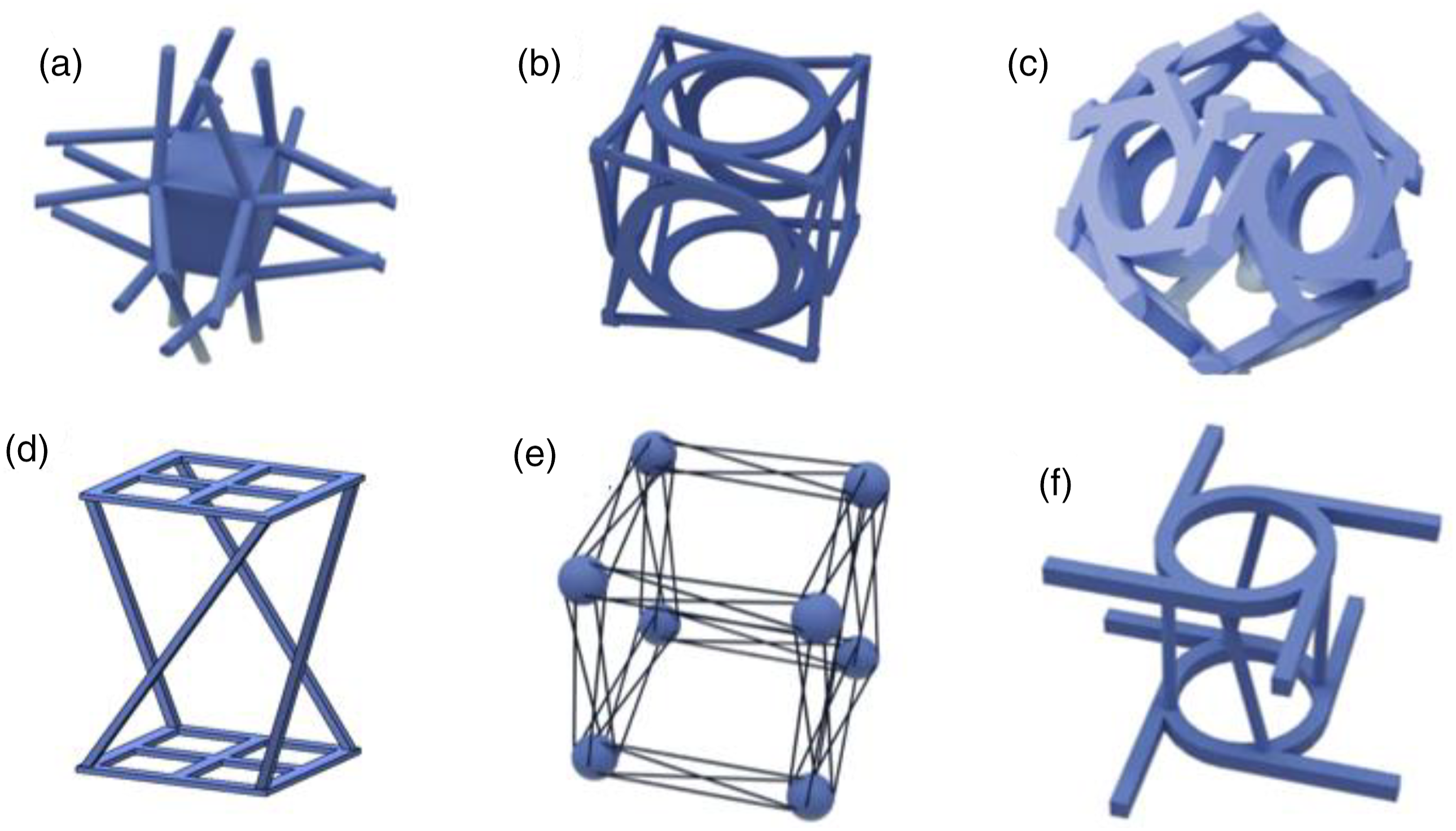
Metamaterials are constructed using multiple unit cells arranged periodically, with the overall structural properties being governed by the properties of these unit cells.36–40 These properties can include negative stiffness,41,42 negative or zero Poisson’s ratio,43,44 compressive-torsional coupling effects,45–49 and others. Chiral metamaterials with compressive-torsional coupling effects, which possess a versatile nature due to their straightforward structure and customizable dimensions, open up a new way for the systematic design of metamaterials. Figure 1 provides an overview of various designs for these chiral metamaterial unit cells. Moreover, the integration of chirality into mechanical metamaterials represents a significant advancement in engineering design, with its further application lying in the transformation into nonlinear multi-resonator metastructures.
50
French team has proposed a 3D compressive-torsional coupling metamaterial, that comprises numerous cubic unit cells, each of which exhibits a distortion exceeding 2°per unit of axial strain.45,46 Wang et al.
47
applied chiral metamaterials to a section of the robotic arm, effectively managing torsional stresses from both tension and compression. Lin et al.
49
established a constitutive model based on the Cosserat rod theory, facilitating the connection of stiffness parameters from lattice columns of any dimension to the unit cells. When combined, the mass-enhancing effect of the inerter and the compressive-torsional coupling effects of chiral metamaterials yield a noteworthy enhancement. Designs of innovative chiral metamaterials unit cell: (a) cubic-symmetry chiral metamaterial,
38
(b) chiral tetragonal mechanical metamaterial,
51
(c) noncubic crystal symmetry chiral metamaterial, (d) chiral metamaterial lattice columns,
49
(e) cubic chiral metamaterial lattice,
52
(f) anti-tetra-chiral metamaterial.
53
The previous research demonstrated that augmenting the mass of the NES contributes to improved vibration mitigation. However, inerter possess the capability to provide significant inertia with relatively small mass. Leveraging this characteristic of the inerter, this paper introduces a novel nonlinear energy sink with inerter structure, integrating the inerter mechanism using chiral metamaterial. This innovative approach allows for effective vibration suppression while maintaining a compact and efficient structural design. This paper is organized as follows: Sect. 2 describes the structure and mechanism of PNESI, and the PNESI-cantilever beam system dynamic model is established in Sect. 3. An optimization and some simulations of the PNESI-cantilever beam system on the vibrations are presented in Sect. 4. Sect. 5 comprises an experimental verification, and the concluding section provides key insights and conclusions.
Design of PNESI
Structure of PNESI
The schematic diagram of the PNESI-cantilever beam system is depicted in Figure 2, where PNESI is attached to the cantilever beam system with lightweight connector. PNESI consists of a piecewise nonlinear NES and a chiral inerter component, jointly forming a 2DOF structure. The piecewise linear stiffness of PNESI is provided by piecewise linear composite beams. The chiral metamaterials, through the compressive-torsional coupling effects, induce both linear motion and torsional motion in the inerter mass block. This combined motion results in inerter amplification, significantly enhancing the overall structure mass. Schematic diagram of PNESI-cantilever beam system.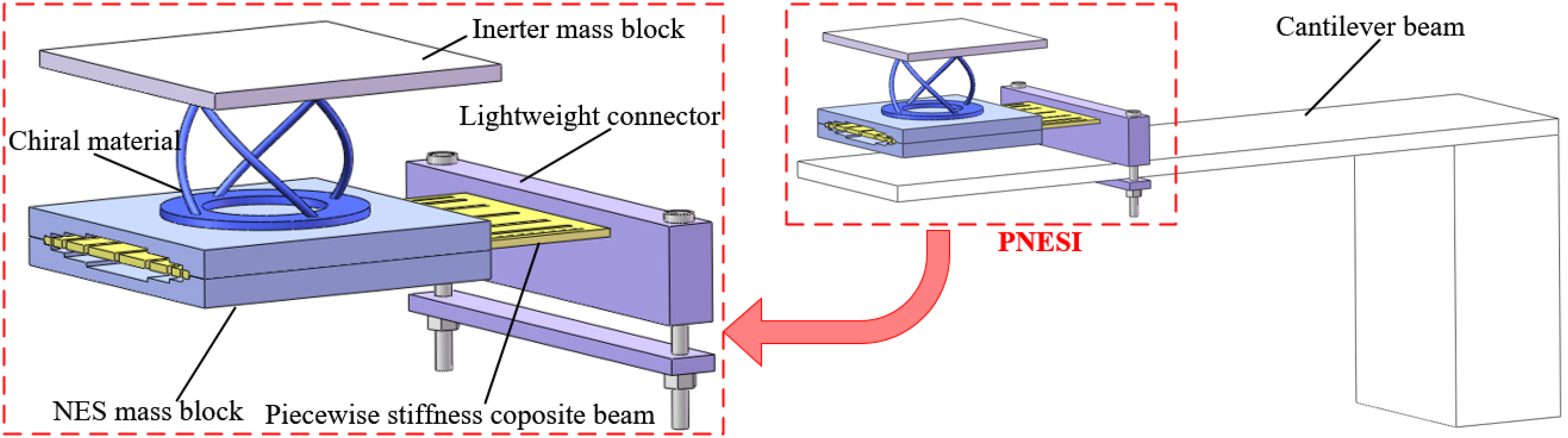
Inerter mechanism with chiral metamaterials
Chiral metamaterials exhibit a remarkable compressive-torsional coupling phenomenon, wherein the application of axial compression or stretching force results in torsional deformation within inclined rods, thereby engendering distinctive macroscopic behaviors. Figure 3(a) illustrates a typical chiral metamaterial structure, comprising two vibrator rings and four inclined rods. The vertical distance between the rings is denoted as h, while the unit cell features a circumcircle with radius r. The inclined rods, arranged in a chiral manner, are distributed along the circumference of the vibrator rings. It is noteworthy that the vibrating ring can adopt alternative configurations, including discs or plate structures, offering flexibility tailored to specific requirements. The circular cross-section diameter of the inclined rods is represented by d, while the inclination angle Chiral metamaterial unit cell: (a) configuration, (b) different directions.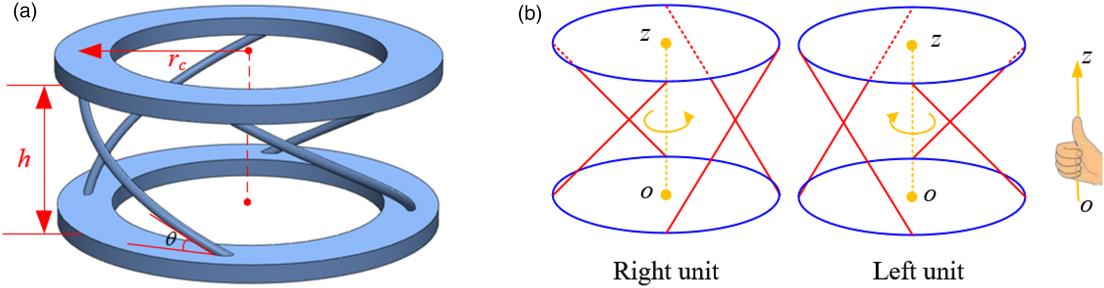
For a comprehensive understanding of the compressive-torsional coupling effects within the chiral metamaterials, a theoretical analysis is performed on the twist deformation exhibited by the kth unit cell under z-axial loading conditions. Figure 4 illustrates the simplified theoretical model of the structure, which highlights the displacement in the y-direction, denoted as y
k
, can be written as Geometrical relationship.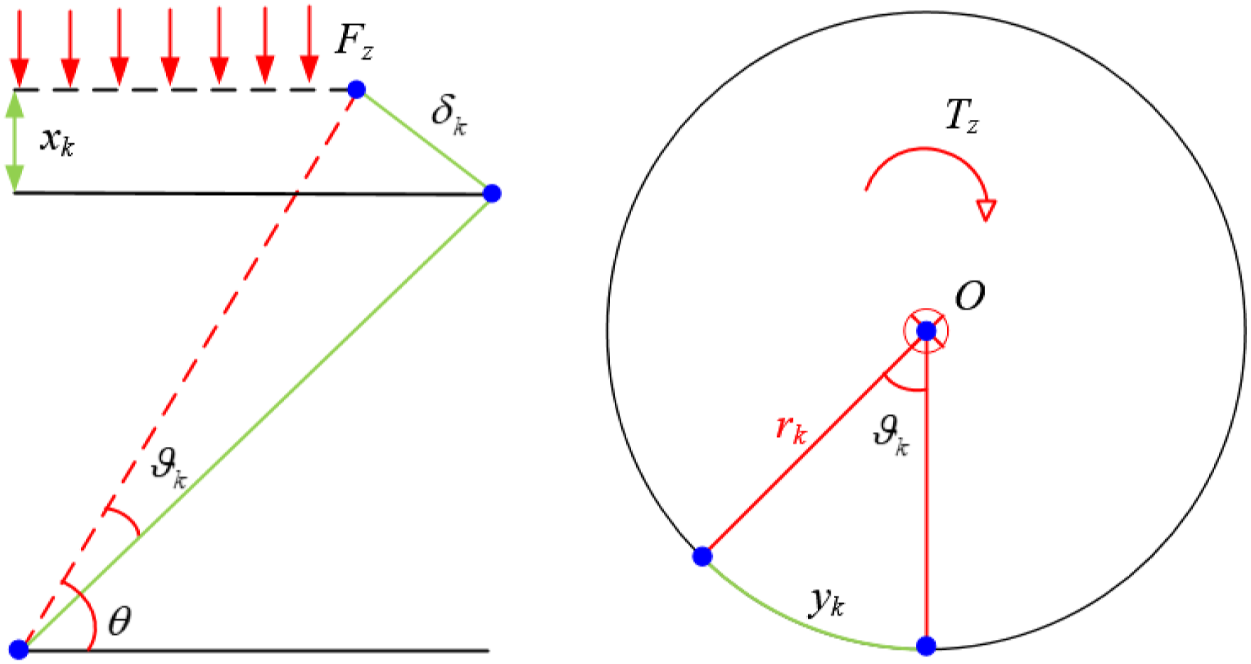

The axial displacement x
k
and the rotational displacement

Considering the coupled axial and torsional motion, as indicated by equation (2), the deflection can be expressed as

Assuming small deformations, the bending stiffness
54
of the inclined rod is calculated as

The dynamic model of the inerter mechanism is depicted in Figure 5. This structural configuration undergoes simultaneous axial and rotational motion, with both behaviors dependent on the displacement of the inerter’s terminals. Consequently, it can be assessed as a semi-definite system, analyzed independently without consideration of any connections to the ground. Dynamic modal of the PNESI.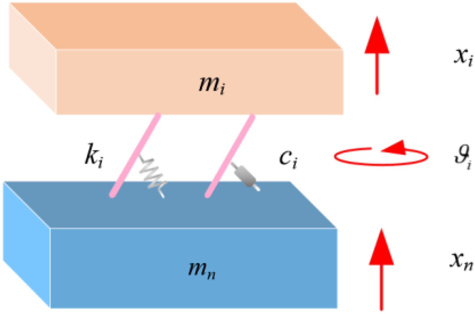
Piecewise linear stiffness beams
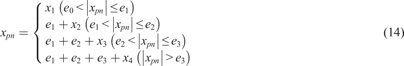
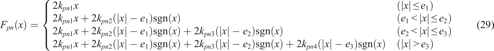
Conventional NES devices, featuring cubic nonlinear stiffness, are designed to absorb energy from external vibration sources. The incorporation of the cubic stiffness term induces a pronounced nonlinear effect, facilitating effective energy dissipation within the system. To simplify the analysis of the nonlinear structure, the approach of fitting cubic nonlinear stiffness by utilizing piecewise linear stiffness has been proposed, which is more practical for engineering purposes.21,55 The force-displacement relationship in the dimensionless representation of cubic stiffness can be written as Structure of piecewise nonlinear composite beam: (a) geometric parameter, (b) clearance, (c) force and displacement curves.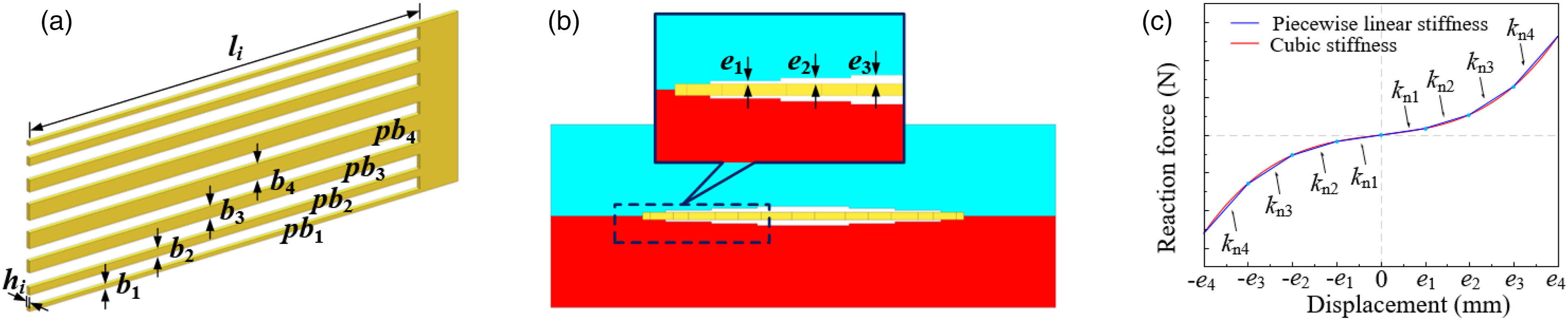


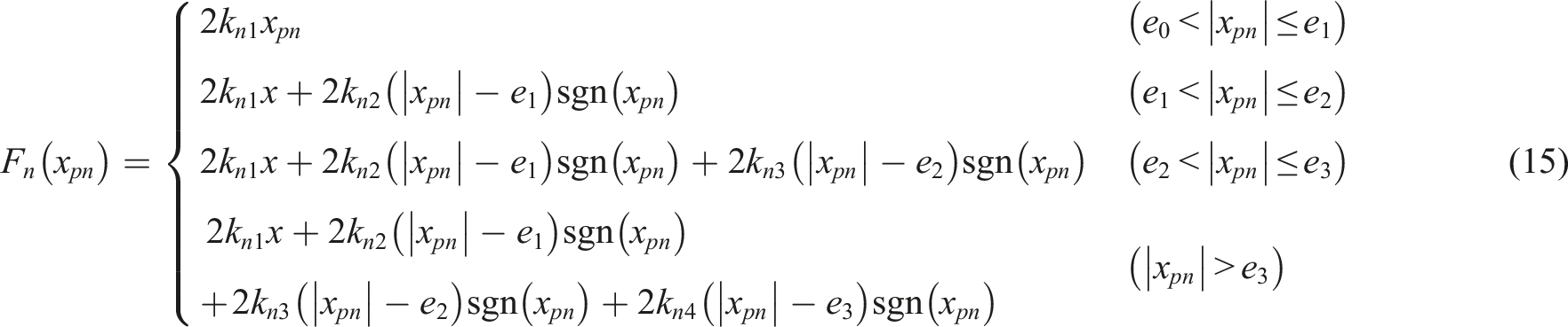
As illustrated in Figure 6(b), three different clearances (e1, e2, and e3) exist between the piecewise nonlinear composite beam and NES mass block. With increasing vibration amplitude, the piecewise nonlinear beams with different clearances progressively come into contact with the mass block, leading to an increase in the stiffness of the NES. The conventional NES exhibits nonlinear stiffness following a cubic relation, a piecewise linear stiffness representation k ni is employed to approximate the cubic nonlinear stiffness. The force and displacement curves of both piecewise linear stiffness and cubic stiffness are depicted in Figure 6(c). It is observed that the relationship between force and displacement of piecewise linear stiffness, after fitting, closely aligns with that of cubic stiffness. Both methods serve the same function in providing nonlinear stiffness to the NES.57,58
Modeling and analysis of PNESI cantilever coupling system
Model analysis
As illustrated in Figure 7, the integration of the PNESI into the cantilever beam establishes the PNESI-cantilever coupling system. The theoretical model of the cantilever beam is based on the Euler–Bernoulli beam theory, with the dynamic response determined by given geometric parameters, including the width Schematic diagram of the PNESI-cantilever system.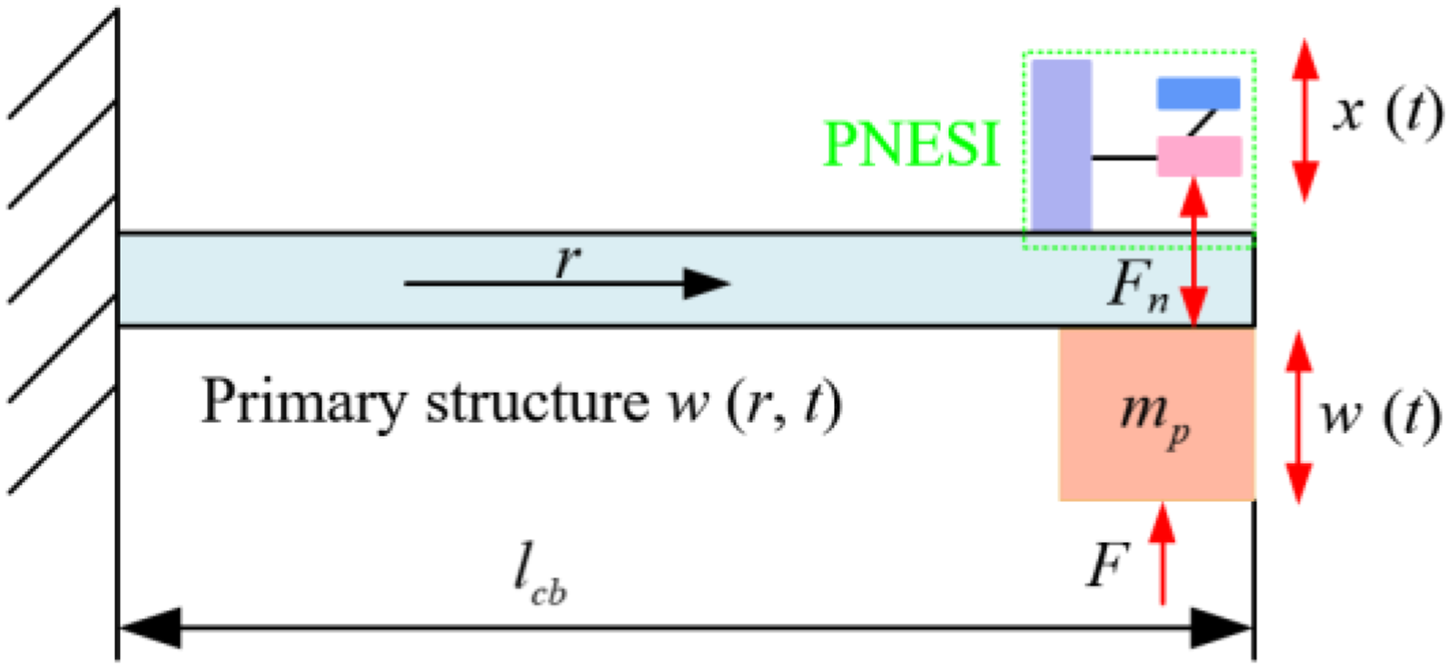
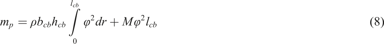
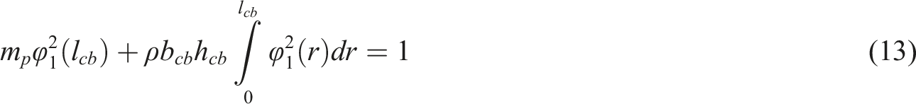
The lumped mass is attached to the end of the cantilever beam, and the modal shape is written as

The


The mode shape coefficients
Assume that
The nonlinear reaction force Fn is generated and can be expressed as
The damping characteristics of the piecewise nonlinear beam vary with changes in the clearances between the beam and the NES mass block. This damping property can be described as piecewise linear damping, with a specific expression as

The inerter structure exhibits two planar degrees of freedom, namely the translation

Referring to Figure 4, and ignoring the chiral metamaterial mass while assuming that each inclined rod adheres to Hooke’s law, the kinetic and potential energies of the inerter can be formulated as


According to the equation (18), the effective axial stiffness of the inerter can be determined as

PNESI-cantilever beam system dynamic model
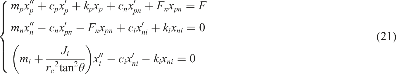
Figure 8 depicts the equivalent model of the PNESI-cantilever beam coupling system. In this configuration, the combined system comprises the equivalent cantilever beam system and the 2-DOF PNESI system, forming a 3-DOF system. It is assumed that the cantilever beam undergoes continuous harmonic excitation, the dynamic equations governing the PNESI-cantilever beam system can be expressed as Dynamic modal of the PNESI-cantilever beam system.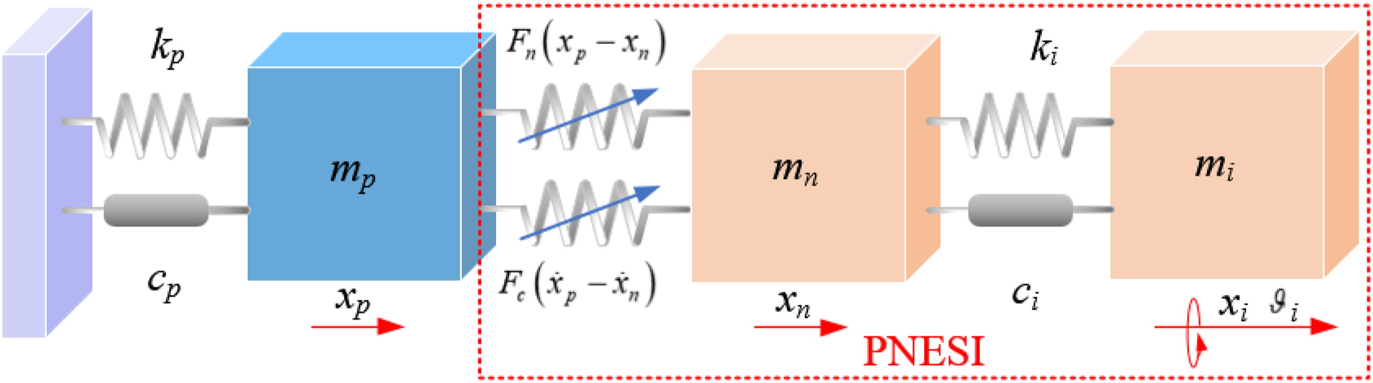
The damping of the primary system and the inertia are expressed as

To facilitate a fair comparison and eliminate the influence of overall mass increase on the vibration suppression in the cantilever beam system resulting from the addition of PNESI, the governing equation for a locked PNESI (where the PNESI contributes to dynamics solely through its mass) attached to the primary system is provided as

Steady-state response analysis
A set of parameters optimizing the PNESI is determined for effective vibration suppression capabilities. Subsequently, these optimized parameters are employed to investigate the influence of the PNESI structure on steady-state vibration mitigation of the cantilever beam system. Furthermore, the impact of different variations in the parameters on the vibration suppression performance of the PNESI structure is explored.
Parameters of the PNESI cantilever beam.
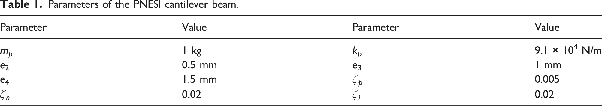
The fourth-order Runge–Kutta method is employed to solve the ordinary differential equation (Eq.(21)), facilitating the numerical solution of the PNESI-cantilever beam system in both the time domain and frequency response. Concerning the given geometric parameters, the 1st order natural frequency of the primary system is determined to be 48.8 Hz. Consequently, the sweep frequency range is set from 10 Hz to 80 Hz. To ensure accuracy in calculations, the initial 2000 data points are excluded during the analysis of the response results.
Vibration suppression capabilities
Under steady-state vibration conditions, assuming the PNESI-cantilever system is initially in a stationary state and subjected to an excitation force, the numerical simulation is initialized with the following initial conditions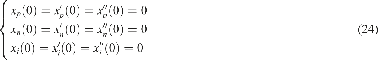
The PNESI parameters are optimized using a GA comprising a population size of 50 individuals and a maximum of 30 iterations. The crossover probability is set to 0.8, while the mutation probability is 0.01. The primary objective of this optimization process is amplitude minimization. Therefore, a single-objective optimization strategy, governed by equation (21) is proposed, which is 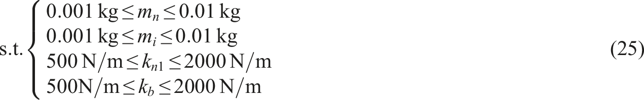
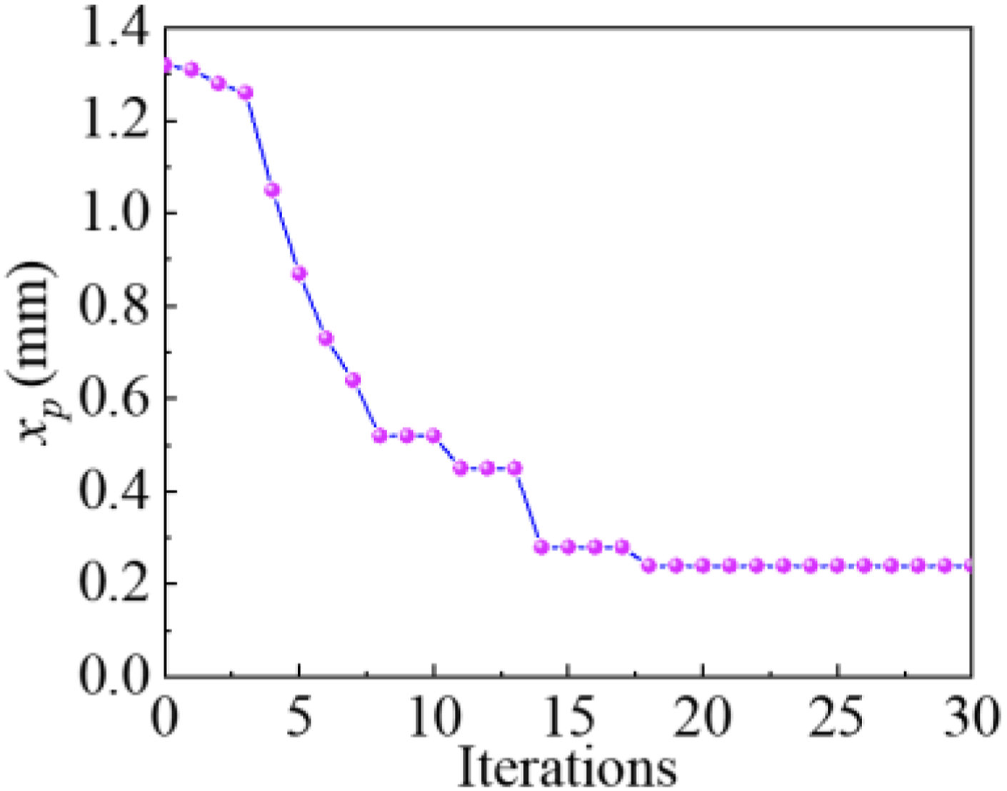
The optimization process of PNESI under steady-state conditions is shown in Figure 9. Subsequently, the optimization results are PNESI optimization iterative.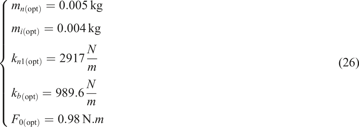
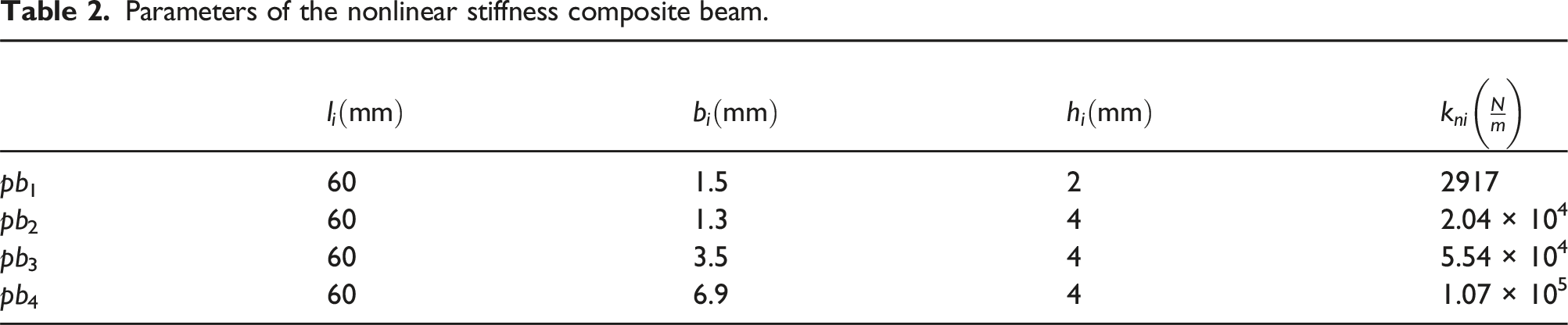
Parameters of the nonlinear stiffness composite beam.
Using optimized parameters, a thorough analysis is conducted on the steady-state vibration of the PNESI-cantilever system. The investigation focused on the vibration suppression performance of both the integrated locked PNESI and activated PNESI. The maximum percentage reduction in resonance amplitude after incorporating PNESI is denoted as 
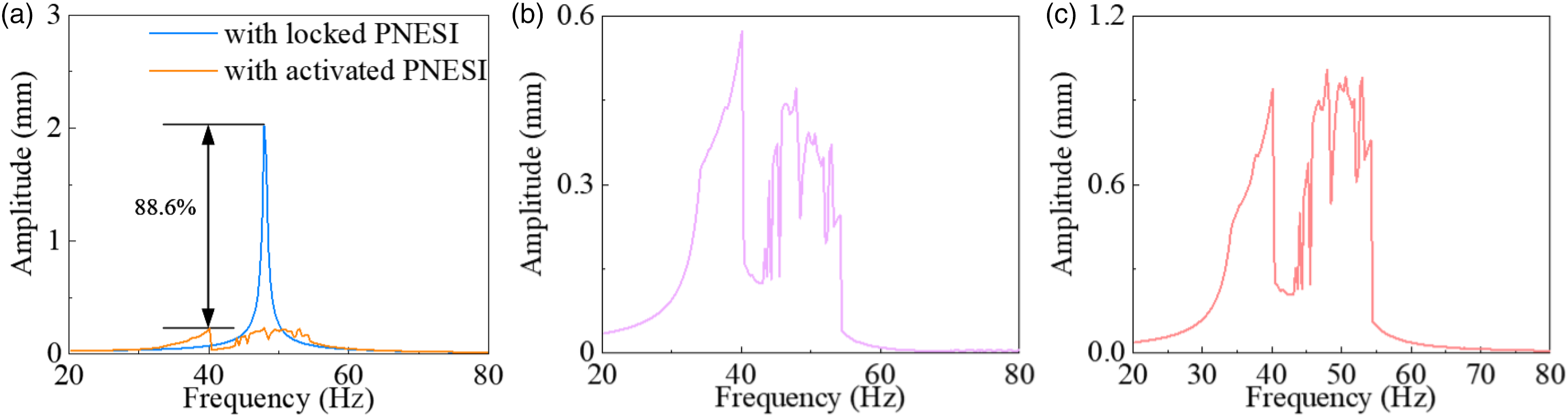
The amplitude frequency curve of the PNESI-cantilever beam coupling system is depicted in Figure 10. As illustrated in Figure 10(a), the locked NESI-cantilever system undergoes forced vibration when subjected to periodic excitation. The results demonstrate a pronounced resonance peak in the cantilever system, with an estimated critical speed of approximately 48 Hz. At resonance, the amplitude of locked PNESI-cantilever system x
p
, reaches a peak of 2.02 mm. However, the introduction of activated PNESI result in a significant reduction in vibrations, as evidenced by the decreased x
p
value of 0.24 mm. This significant reduction demonstrates the remarkable vibration suppression capabilities of PNESI, achieving an 88.6% reduction in vibration. Furthermore, in Figures 10(b) and (c), the maximum values of x
n
and x
i
are measured at 0.57 mm and 1.01 mm, respectively. These results demonstrate the energy transfer from the cantilever beam to the PNESI, affirming its capability to efficiently absorb energy and mitigate vibrations. PNESI-cantilever system amplitude frequency response curves: (a) x
p
, (b) x
n
, (c) x
i
.
Further evidence of the efficiency of PNESI in mitigating vibration is revealed in Figure 11(a), where the locked NESI-cantilever beam system demonstrates periodic motion, contrasted with the activated PNESI-cantilever beam system exhibiting nonlinear beat vibrations. PNESI-cantilever system time history curves: (a) x
p
, (b) x
n
, (c) x
i
.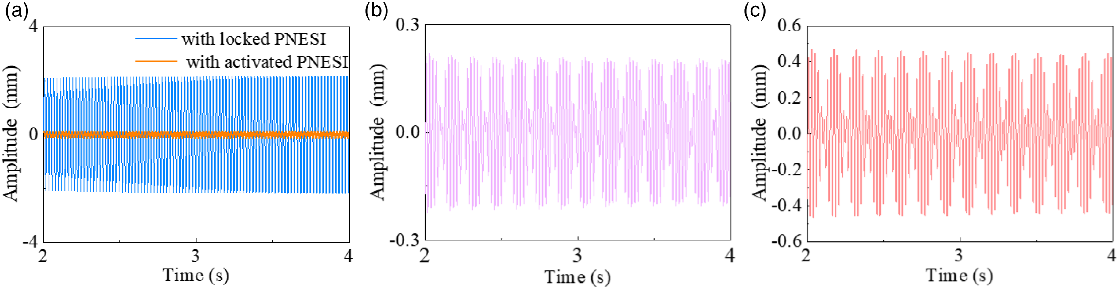
Notably, the coupling system demonstrates a modulated response at 48 Hz, indicative of quasi-periodic behavior, which enhances overall effectiveness of PNESI in vibration suppression.
Parameter analysis
Firstly, an analysis is conducted to investigate the influence of various parameters on the inertance b and equivalent stiffness k i of the inerter structure. Referring to Eq. (17), b is influenced by the diameter of the inerter mass a, the radius r and the initial angle θ of the chiral metamaterial. On the other hand, k i is influenced by the cross-sectional diameter d, length l of the inclined rod and initial angle for the chiral metamaterial.
Figures 12(a) and (b) present the influence of parameter variations on both the inertance b and equivalent stiffness k
i
of the inerter structure, respectively. Notably, chiral materials offer a broad range of the inertance and stiffness values, enabling a more precise match to the parameters required for vibration suppression in diverse primary systems. Figure 12(c) illustrates the influence of variations in θ on the inertance and equivalent stiffness of the inerter structure. As θ increases, both the inertance and equivalent stiffness decrease. Effect of size parameter of chiral metamaterial: (a) effect of the b, (b) effect of the k
i
, and (c) effect of the θ.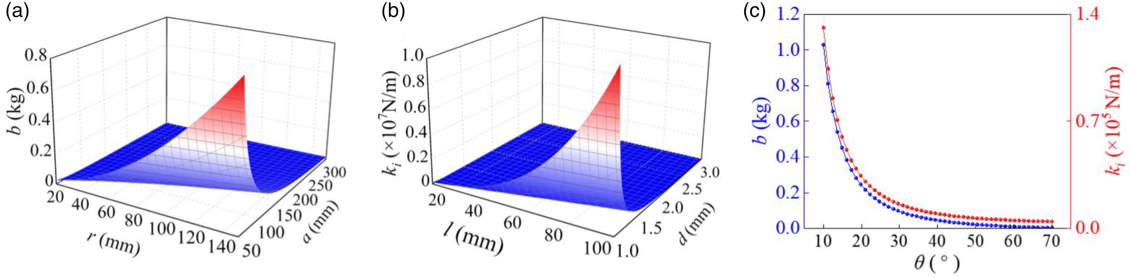
Then, an analysis is conducted to investigate the effect of various parameters of PNESI on its vibration suppression capabilities. These parameters including NES mass m
n
, NES 1st linear stiffness kn1, inerter equivalent mass m
eq
, inerter equivalent stiffness k
i
. It is worth noting that m
eq
incorporates both the inerter mass m
i
and inertance b. Given the relationship b = 16.3 m
i
. the primarily focus of m
eq
revolves around the variation of m
i
. The results of this analysis are presented in Figures 13–16. Steady-state vibrations on change of m
n
: (a) x
p
, (b) x
n
, (c) x
i
. Steady-state vibrations on change of m
i
: (a) x
p
, (b) x
n
, (c) x
i
. Steady-state vibrations on change of kn1: (a) x
p
, (b) x
n
, (c) x
i
. Steady-state vibrations on change of k
i
: (a) x
p
, (b) x
n
, (c) x
i
.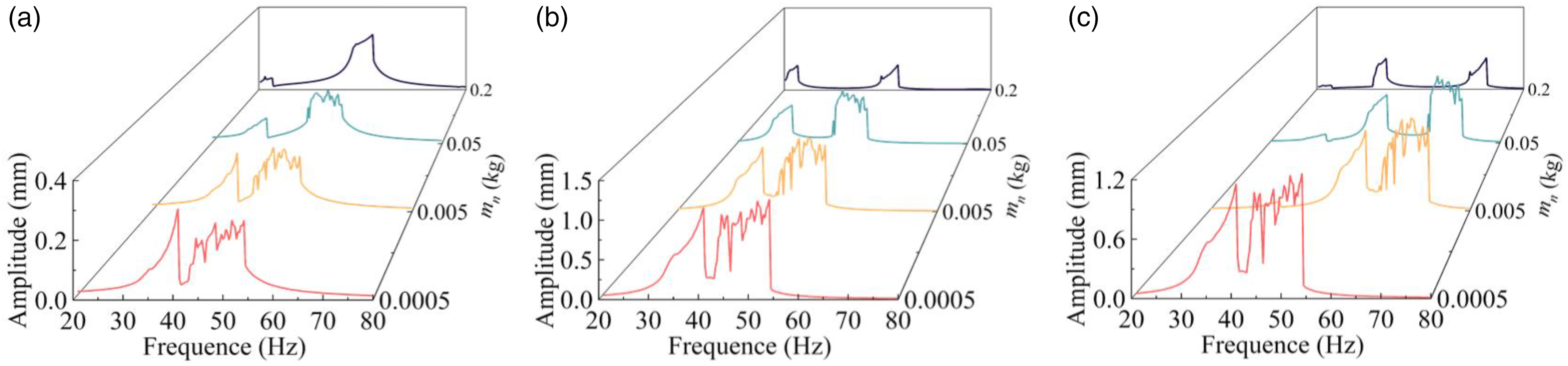
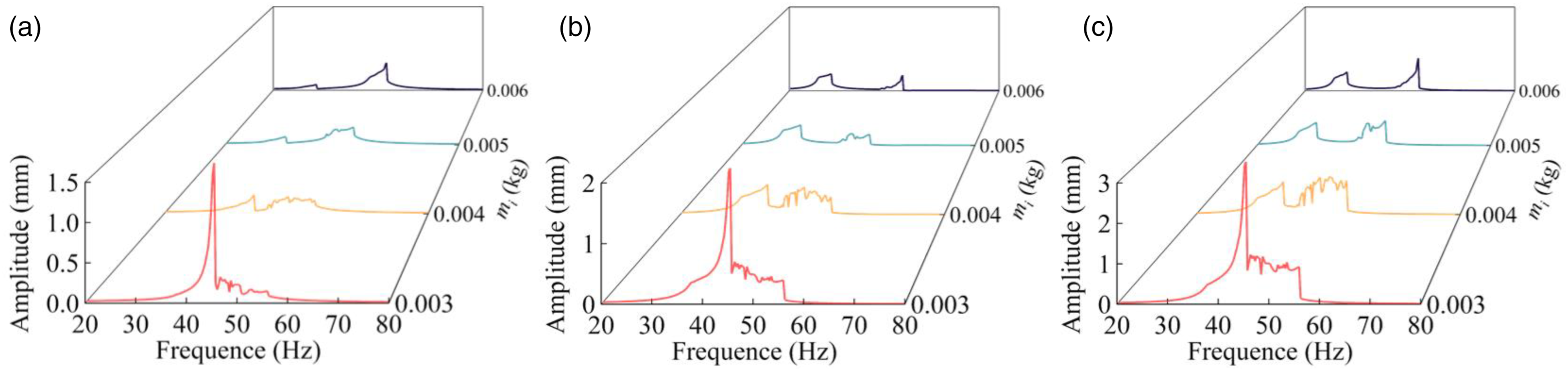
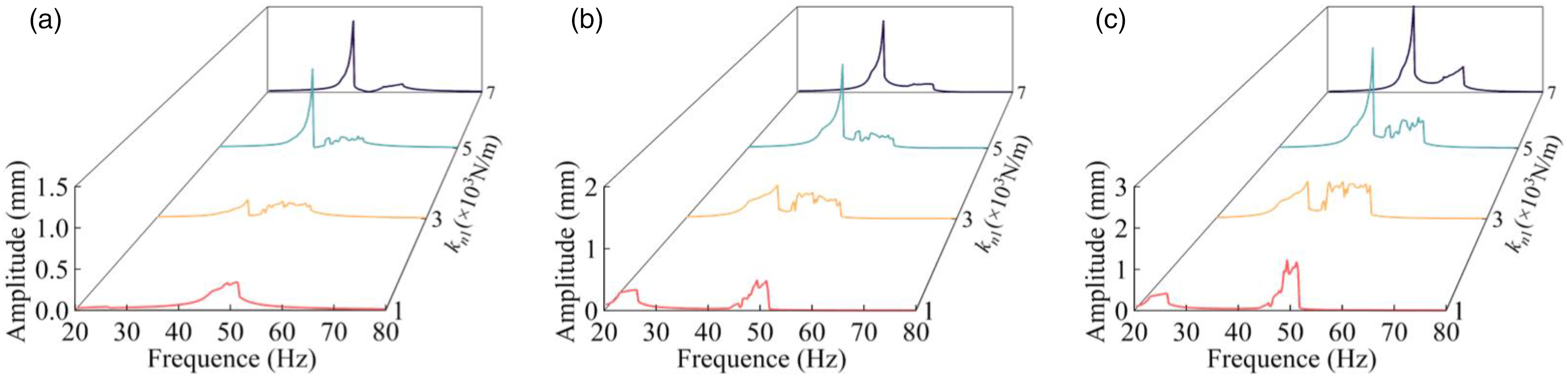
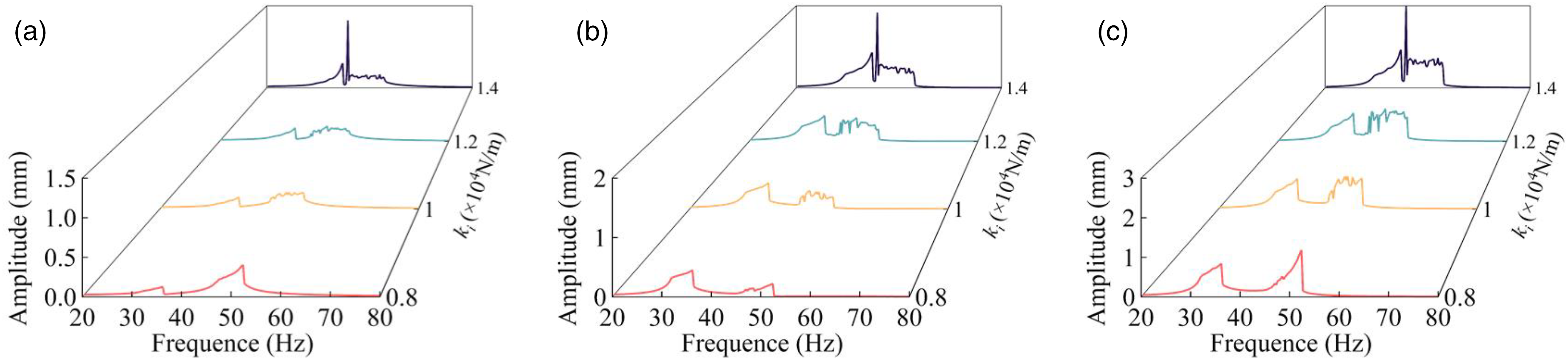
Figure 13 exhibits the influence of NES mass m n on the amplitude frequency response of the coupling system. It is observed that the optimal additional mass for the coupling system corresponds to m n = 0.005 kg. When m n is decreased to 0.0005 kg, the cantilever beam vibration amplitude x p surpasses that observed for m n = 0.005 kg. As m n continues to increase, the x p also increases, while the nonlinear characteristics of the coupling system become less pronounced. Interestingly, even at m n = 0.0005, PNESI maintains commendable vibration suppression capability, indicating the significant role played by the inerter structure in suppressing vibrations on the cantilever beam.
Figure 14 illustrates the influence of the inerter mass m i in the PNESI-cantilever system. When m i = 0.003 kg, the equivalent mass is insufficient to engage the NES effectively, resulting in a response curve resembling that of a system without NES. Consequently, the vibration suppression capabilities of PNESI are negated. In contrast, when m i = 0.004, the coupling system attains optimal vibration suppression performance. However, as m i surpasses this value, the nonlinear characteristics of the coupling system gradually diminish, and the response amplitude increases progressively.
In Figure 15, the influence of the 1st linear stiffness kn1 on the stead-state vibrations amplitude is depicted. As kn1 increase, the amplitude of coupling system initially decreases, followed by a subsequent increase. However, when kn1 reaches 5000 N/m, the PNESI structure gradually loses its capability to effectively suppress vibrations. At kn1 = 1000 N/m, the structure exhibits an effective vibration suppression range from 44 Hz to 54 Hz. Similarly, at kn1 = 3000 N/m, the effective vibration suppression range expands to 38 Hz to 57 Hz. These findings suggest that an appropriate 1st linear stiffness can enhance the nonlinear characteristics of the structure, thereby broadening the frequency range over which vibration suppression is effective. Comparable trends are observed in the behavior of the inerter equivalent stiffness, as illustrated in Figure 16.
Comparison analysis
To demonstrate the efficacy of the PNESI, a comparison is conducted between the PNESI and conventional NES. Notably, to ensure equitable comparison, the cubic stiffness characteristic of the conventional NES is substituted with piecewise linear stiffness. Consequently, this section compares and analyzes the vibration reduction capabilities of the PNESI and the piecewise nonlinear NES (essentially the PNESI without the inerter structure). The piecewise nonlinear NES is assembled into the cantilever beam, with its dynamic model depicted in Figure 17. The dynamic model of the piecewise nonlinear NES-cantilever beam system.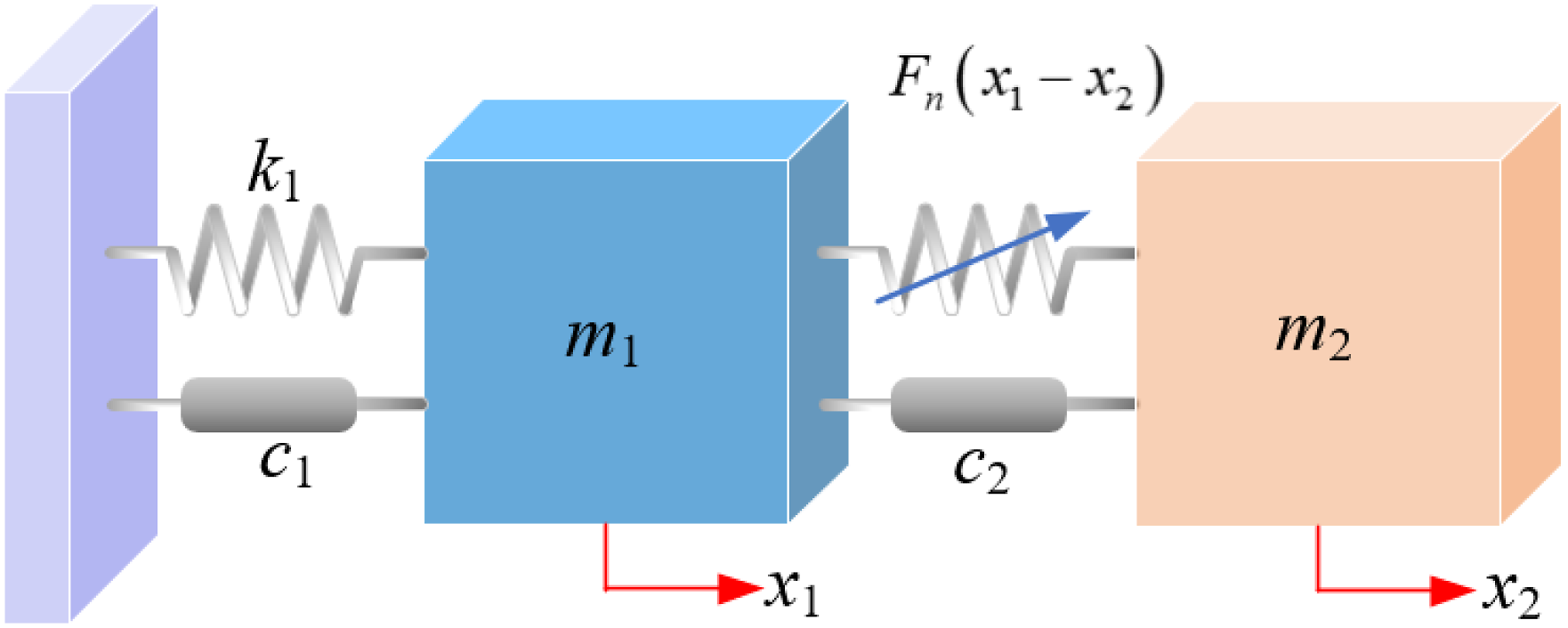
According to Newton’s second law, the dynamic equation of the piecewise nonlinear NES-cantilever beam system is established as
Firstly, the mass of the piecewise nonlinear NES is set to equal to the combined mass of the NES and the inerter component of the PNESI, resulting in a mass of 0.009 kg. Additionally, the relevant parameters of the piecewise linear stiffness are set to be consistent with those of PNESI. This adjustment ensures equivalent mass and stiffness characteristics between the two systems, facilitating a reliable and meaningful comparison. An appropriate excitation force amplitude of
In Figure 18, the amplitude frequency response curve of PNESI is compared with that of the corresponding piecewise nonlinear NES. Upon integrating the piecewise nonlinear NES into the primary system, there is no significant alteration observed in the amplitude of the primary system’s vibrations. This indicates that given the same mass configuration, the piecewise nonlinear NES does not exhibit any discernible vibration mitigation effect on the primary system. In contrast, the performance of PNESI in attenuating vibrations is notable and remarkable. Comparison of steady-state vibration between piecewise nonlinear NES and PNESI.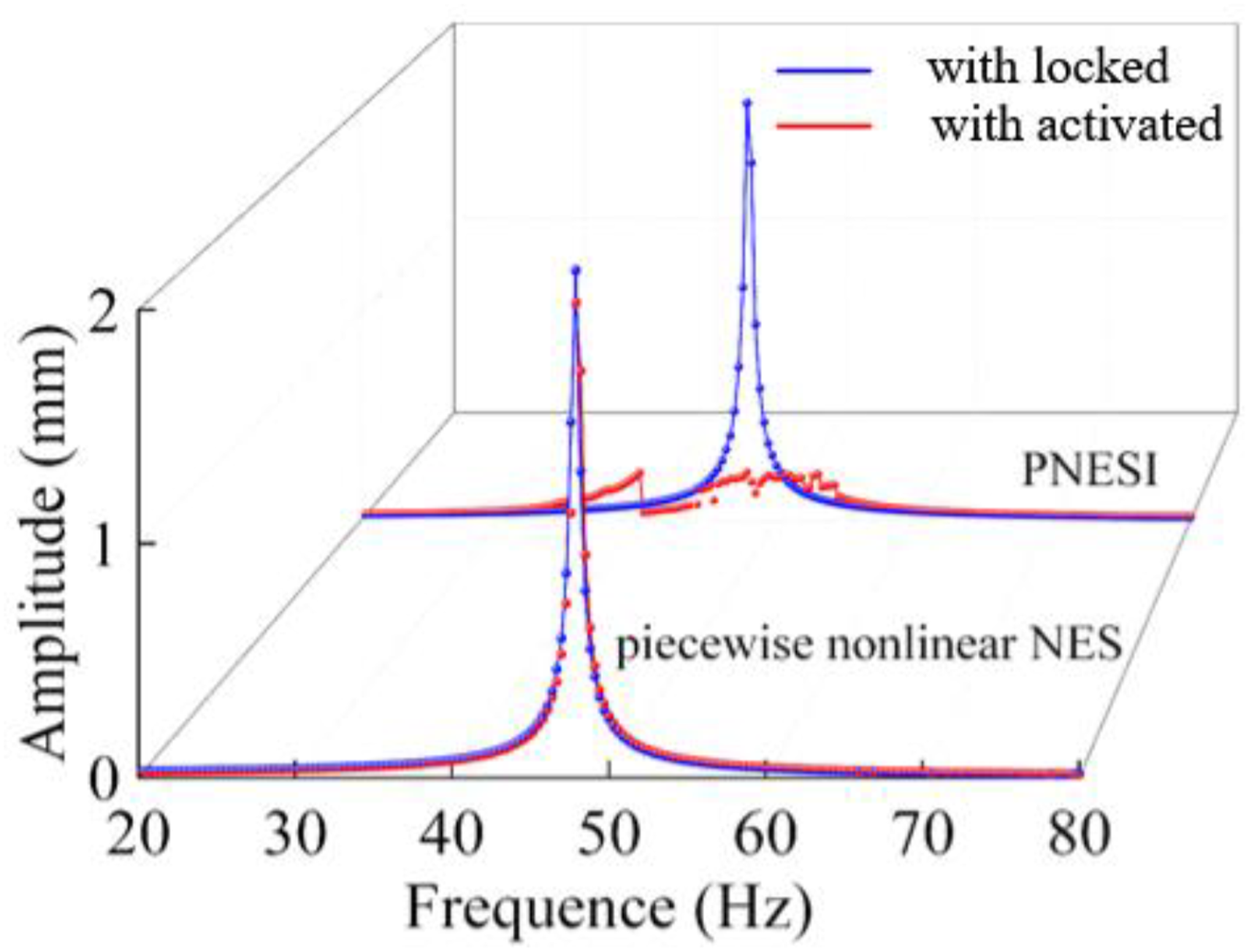
Subsequently, a genetic algorithm is employed to optimize the piecewise nonlinear NES, resulting in a satisfactory solution. The optimization process decreases the amplitude A
d
from 0.8 mm to 0.4 mm, as depicted in Figure 19. The optimal parameters, derived from the convergence results, are determined to be m2 = 0.05 kg, kpn1 = 208 N/m. Utilizing these optimized parameters, a simulation analysis is conducted to evaluate the vibration suppression of the piecewise nonlinear NES-cantilever beam system under steady-state excitation. Piecewise nonlinear NES optimization iterative.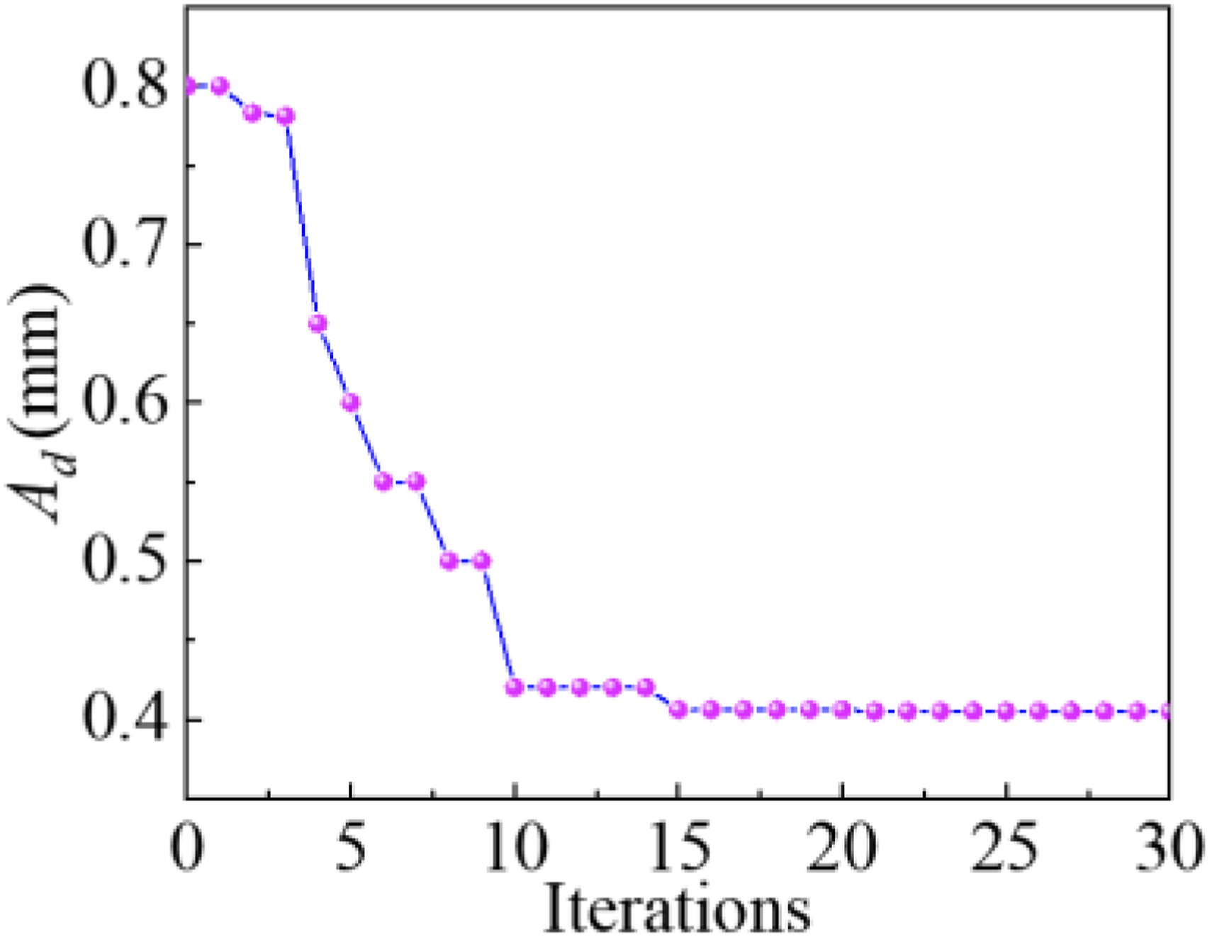
The amplitude-frequency response curve of both the piecewise linear NES and PNESI are illustrated in Figure 20. Upon conducting parameter optimization, it is evident that the vibration suppression percentage achieved by the piecewise nonlinear NES is 79.4 %, which is lower than the 88.6 % achieved by PNESI. Additionally, it is observed that the vibration mitigation range of the piecewise nonlinear NES is comparatively smaller. Comparison between optimize piecewise nonlinear NES and PNESI.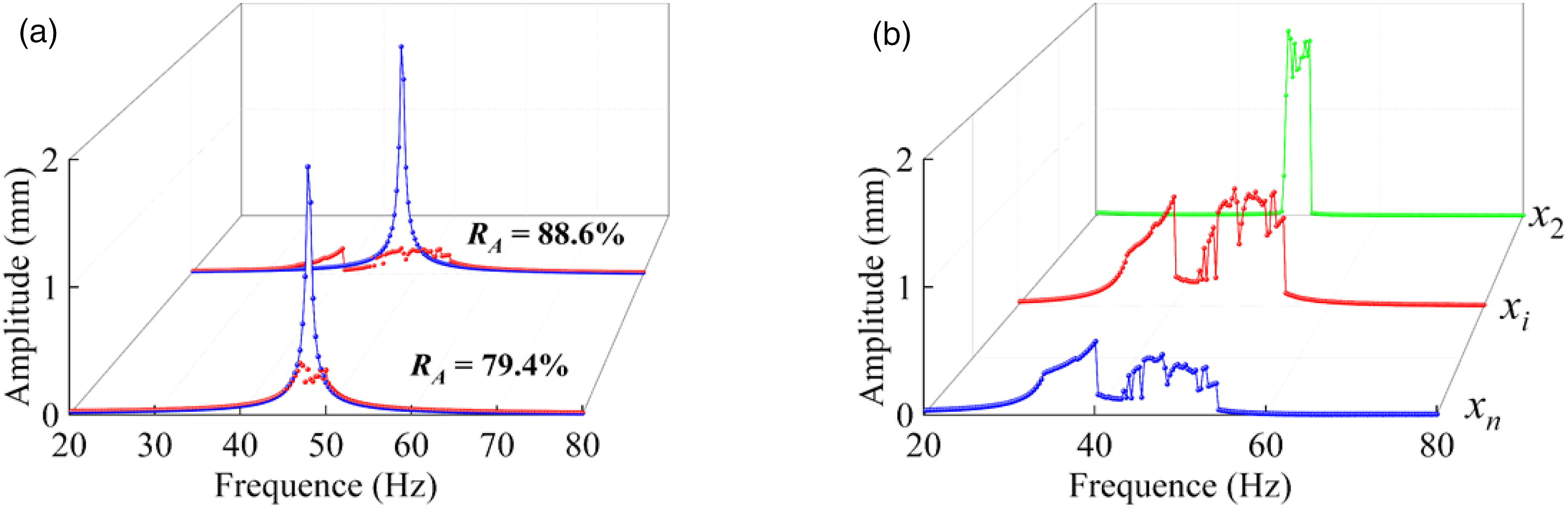
Comparison of two groups of different conditions reveals that, under identical mass conditions to PNESI, the piecewise linear NES exhibits no inhibitory effect on the cantilever beam system due to its lack of the mass amplification effect of inerter structures. However, even after parameter optimization for the piecewise linear NES, its vibration reduction capability remains lower than that of PNESI. It is noteworthy that the mass of the piecewise linear NES after parameter optimization is significantly greater than that of PNESI. These findings further demonstrate the superior vibration suppression performance and mass amplification capability of PNESI.
Experimental validation
Experimental devices
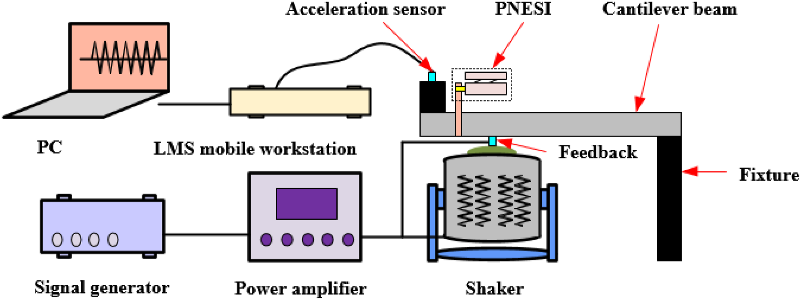
As illustrated in Figure 21(a), the experimental device for the PNESI-cantilever beam system has been constructed. The PNESI is connected to the cantilever beam via lightweight connectors, whose structure is depicted in Figure 21(b). In this setup, the pb1 section of the piecewise linear composite beam is fixed with the NES mass block, while the other sections of the beams exhibit varying clearances with the NES mass block. And the experimental flow chart is described in Figure 22, where the harmonic signal from the shaker, connected to the cantilever beam, is generated by the signal generator and amplified through the power amplifier. Acceleration sensors (type and sensitivity: CA-YD185, 0.48 mV/m·s−2) are mounted on the primary system, and the vibration response signals are collected and analyzed using the LMS SCADAS system. PNESI cantilever beam system experimental device: (a) experimental system, (b) detail diagram of PNESI. Experimental flow chart.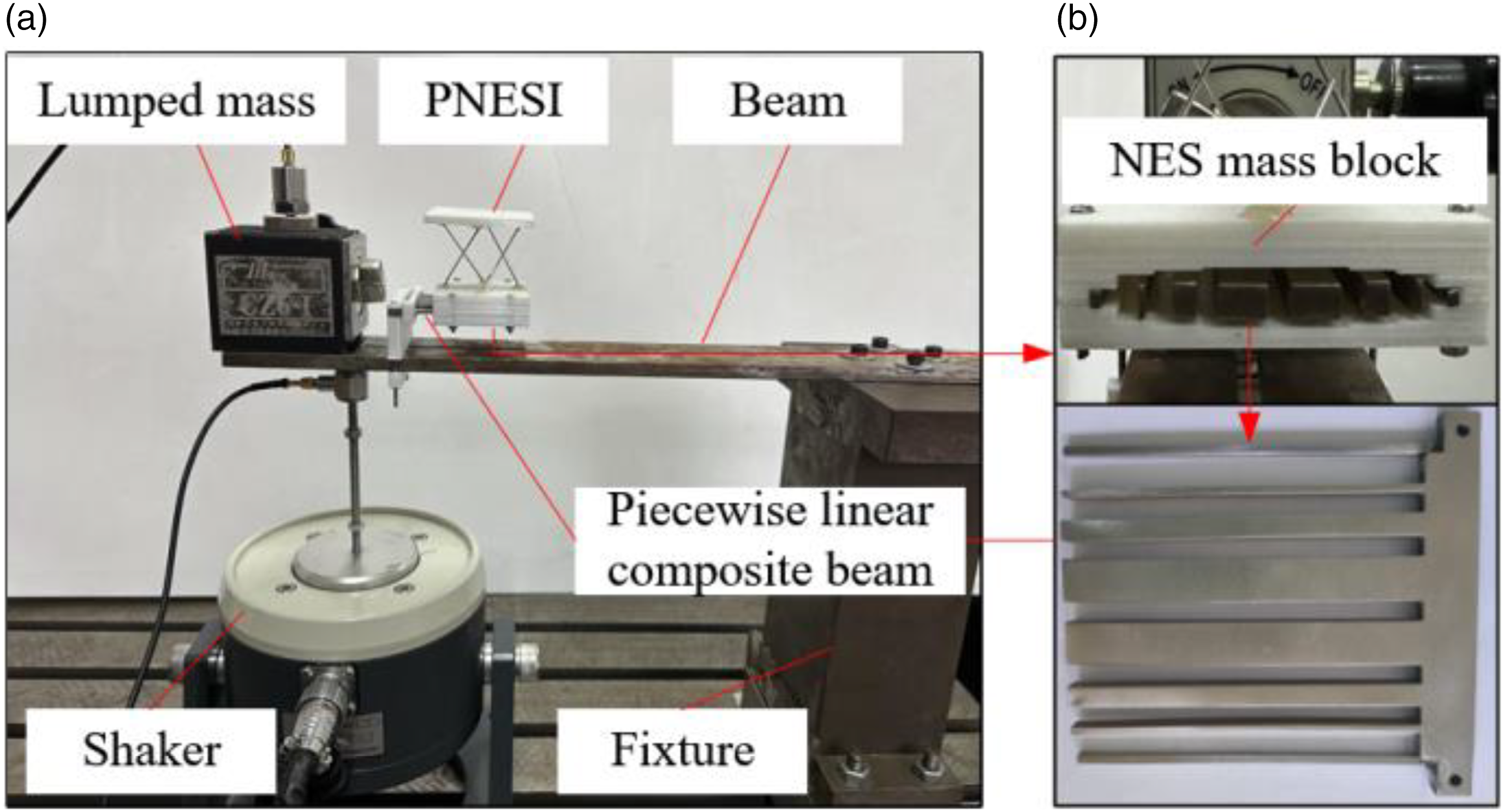
Experimental results
Frequency sweep measurement
The frequency sweep of the PNESI-cantilever beam system is conducted within a range of 1-80 Hz, with a sweeping rate of 1.5 Hz/s. The time history response curve is illustrated in Figure 23. The blue line exhibits significant vibration fluctuations in the time interval between 35s and 40s, representing the vibration response of the cantilever beam system with the locked PNESI in Figure 23(a). After being equipped with PNESI, the vibration response of the cantilever beam system experiences a substantial attenuation, which is described by red line in Figure 23(b). This observation demonstrates the efficacy of PNESI in mitigating the vibration response of the cantilever beam system. Primary system frequency domain curves: (a) with locked PNESI, (b) with activated PNESI.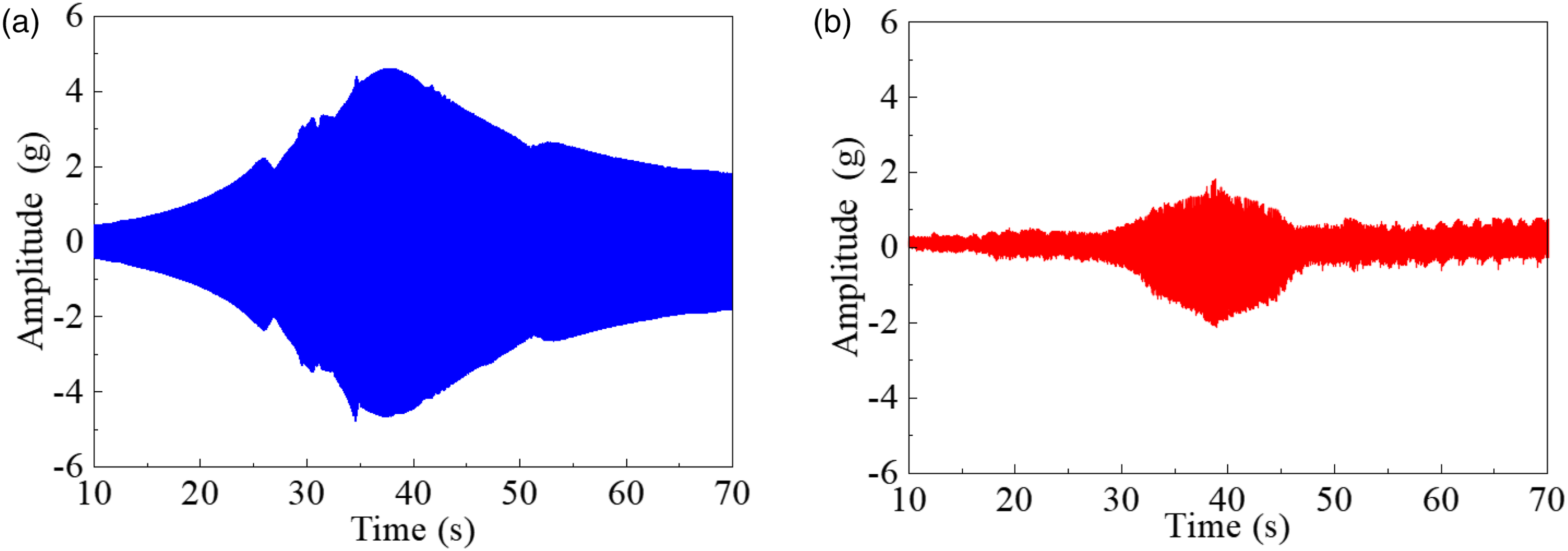
The time history curve depicted in Figure 23 along with the corresponding excitation force, undergo Fourier transformation to yield the amplitude-frequency response curve as presented in Figure 24. The peak of the blue curve occurs at 48.1 Hz. Subsequently, upon the addition of PNESI, a notable mitigation in the peak of the 1st-order vibration responses is observed. At 48.1 Hz, the amplitude reaches its maximum value at 1.1 g. With the addition of PNESI, depicted by the red line, the response amplitude rapidly decreases, and the maximum amplitude of the primary system is reduced to 0.41 g. This indicates that PNESI achieves a vibration mitigation of approximately 62.7% at the peak amplitude of the cantilever beam system. The vibration responses amplitude of the cantilever beam.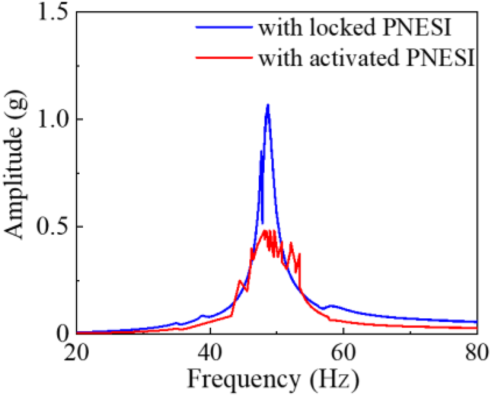
Figure 24 corresponds to the amplitude-frequency response curve described in Figure 10(a) of Section 4.1. It is observed that both the numerical simulations and experimental results reveal a first-order resonance frequency band centered around 48 Hz, with vibration suppression percentages of 88.6% and 62.7%, respectively. These findings affirm the effectiveness of PNESI. However, uncontrollable factors encountered during the experimental process, such as measurement errors, contribute to the observed disparities in vibration suppression percentages between the simulation and experimental results.
Constant frequency measurement
The constant frequency measurement test, conducted at 48.1 Hz, which falls within the 1st-order critical speed resonant region of the cantilever beam, yielded significant effects. Figure 25(a) illustrates the vibration response of the primary system equipped with the locked PNESI at 48.1 Hz. As depicted in Figure 25(b), the addition of activated PNESI to the cantilever beam result in a rapid reduction in the amplitude of displacement fluctuation. This research demonstrates the excellent vibration mitigation capabilities of the PNESI, even under constant frequency conditions, further validating its effectiveness in controlling vibrations in the cantilever beam system. Time history curve at 48.1 Hz: (a) with locked PNESI, (b) with activated PNESI.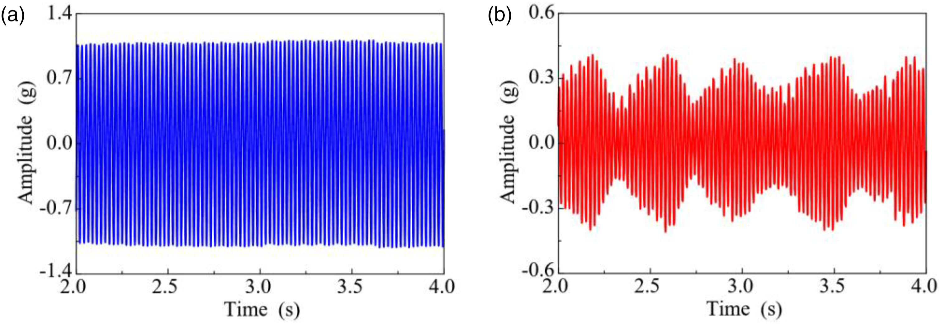
Figure 25 corresponds to the time history curve depicted in Figure 11(a) in Section 4.1. Both numerical simulations and experimental results indicate that the amplitude fluctuation of the cantilever beam system is significantly reduced upon the integration of the activated PNESI, exhibiting beat vibration characteristics.
Drawing from the preceding deliberations, it is concluded that the primary findings obtained from numerical analysis are in agreement with the experimental tests. Consequently, PNESI proves to be an effective vibration mitigation technique for cantilever beam systems.
Conclusions
To address the complexity associated with traditional inerter structures, a simple and lightweight PNESI structure is designed. This design leverages the compressive-torsional coupling characteristics of chiral metamaterials to achieve inerter amplification, which has been successfully applied for vibration suppression in cantilever beam systems. The key research findings are summarized as follows. (1) The compressive-torsional coupling characteristics of chiral materials facilitate stroke amplification, enabling the realization of a simple and reliable inerter mechanism through reasonable utilization. Furthermore, the inerter amplification factor can be effectively modulated by adjusting the size parameters of the chiral materials. (2) Upon the integration of PNESI, a notable reduction is observed in the resonance peak within the primary system, while the amplitude of the anti-resonance point almost disappears. This observed behavior underscores the effectiveness of PNESI in mitigating vibrations within the primary system. (3) The introduction of inerter structure in PNESI can greatly reduce its required mass. Conversely, under equivalent mass conditions, the piecewise nonlinear NES lacks inhibition capabilities in the cantilever beam system due to the absence of the mass amplification effect conferred by the inerter structure. Additionally, increasing the mass of the piecewise nonlinear NES fails to achieve the same vibration mitigation performance as PNESI.
Footnotes
Acknowledgments
The authors would like to gratefully acknowledge the National Natural Science Foundation of China (Grant No.52075084) and the Fundamental Research Funds for the Central Universities (Grant No. N2303005) for the financial support for this study.
Declaration of conflicting interests
The author(s) declared no potential conflicts of interest with respect to the research, authorship, and/or publication of this article.
Funding
The author(s) disclosed receipt of the following financial support for the research, authorship, and/or publication of this article: This work was supported by the National Natural Science Foundation of China (Grant No.52075084) and the Fundamental Research Funds for the Central Universities (Grant No. N2303005) for the financial support for this study.