
Abstract
We present the governing equation and study vibrations of multiple crack beams undergoing large deflections subject to transverse loads. First, the primary motion equation is derived using Hamilton’s principle applied to energy functions accounting for cracks. Then we derive a normalized equation governing the vibration of the extensible cracked beam. Single and multiple crack beam examples are considered and analyzed numerically to verify the validity of the derived equations. We propose a modified cracked extensible beam model accounting for the axial force by considering the reduced cross-sectional area. It is expressed by a new reduction parameter. Using the proposed model, we numerically investigate how the cracked extensible beam’s natural frequencies change depending on various model parameters.
Keywords
Introduction
The main goal of this study is to present the governing equations for an
Research on cracked beams has gained considerable attention over the past 20 years from researchers and engineers in the fields of architecture, civil, and mechanical engineering. It focuses on mathematical models, natural frequencies, dynamic analyses, inverse problems and so on.3–6 However, predicting the location and depth of cracks in beams with multiple cracks remains a challenging task. For the identification and estimation of physical parameters, understanding and gaining insights into the dynamic characteristics through direct analysis of the beam is important. 7
Recently8–10 we developed a rigorous mathematical model for extensible beams and derived the existence of their weak (variational) solutions. In this paper, we use finite-dimensional approximations using eigenfunctions (mode shape functions) and investigate the dynamic behavior of the beam under various conditions. A reduction area ratio is introduced to reflect the axial force reduced by cracks, representing the original cross-sectional area’s effective area. Moreover, we use mode shape functions satisfying the patching conditions at the crack point and the Galerkin approximations method for the governing equation.
Now we present the governing equation for cracked extensible beams, leaving details and notations to subsequent sections and the original papers.8,9
Let the cracked beam be positioned over interval Ω = (0, L) at time t ∈ (0, T). Function y = y (x, t) is its deflection at x ∈ Ω, at t > 0. Let
The patching conditions at a crack point x
i
are described by

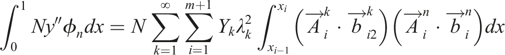
Then the “classical” governing equation for the multi-cracked extensible beam is shown to be

We start with a literature review in the following section. Then we proceed with several sections containing a concise outline of the derivation of the governing equation (1.2). A framework for describing cracked beams, as well as the representation of the cracks by massless springs is presented in Cracked beam and flexibilities. Hilbert spaces H and V containing functions suitable for representing cracked beams are introduced in Variational setting. This section also introduces the critically important operator
The existence of the associated eigenfunctions is discussed in Eigenvalues and eigenfunctions. A method for their evaluation is described together with an example. The governing equation is derived in Equation of motion using the Extended Hamilton’s Principle. Eigenfunction expansions of the solutions are discussed in Eigenfunction expansion of governing equations.
Applications and numerical results contains the major portion of our numerical studies. We consider single and multi-crack extensible beam examples, and validate the presented beam model. In the section, example in Ref. 2 is adopted to estimate the validation of the presented extensible beam equations and the dynamic behavior of the cracked beam. Also, we investigate the change in frequency according to the crack parameters and basis. For the validation of the proposed model, firstly, the linear eigenvalues and corresponding eigenfunctions are compared with the existing literature (Free undamped extensible beam with a single crack). Next, the characteristics of frequency changes for the extensible beam are compared based on the amount of deflection, changes in frequency due to increasing load (Forced undamped extensible beam with a single crack), and frequency changes considering the aspect ratio (Free undamped extensible beam with five cracks). Finally, changes due to the increase in the number of cracks, changes in crack location, and reduction in aspect ratio are observed (Extensible beam with multiple cracks) to examine whether the proposed mathematical model reflects all the required characteristics for an extensible beam with cracks.
Literature review
Generally, there are two theories: the Euler–Bernoulli beam (
An early EB beam theory for beams with cracks is found in Ref. 12. The equations are derived using Hu–Washizu’s variational method. In this process, the stress and strain were assumed to be functions accounting for the cracks, and the governing equation was reduced to a one-dimensional problem.
On the other hand, Ostachowicz and Krawczuk 13 obtained the natural frequency of the cracked beam more easily by deriving an equivalent stiffness or flexibility of the crack point according to the crack depth. Based on their research, Rizos et al. 14 approached the inverse problem by dividing the beam at the point of the crack and applying continuity conditions at the crack.
Following this, many researchers have obtained solutions for cases with multiple cracks by using the determinant of equations derived from crack conditions and boundary conditions. In particular, Shifrin and Ruotolo 15 proposed a method to reduce the order of the determinant and the speed of solving the problem. Khiem and Lien 16 introduced the transfer matrix method. Lin et al. 17 found the eigen-solutions of transverse vibration through patching conditions at the crack point. After that, many studies appeared that dealt with cracks by replacing them with torsional springs. In addition, Caddemi and his colleagues,7,18 have contributed a great deal to the basis of mathematical and engineering theories for expressing this closed-form solution of the multi-crack beam. In Ref. 18, the authors demonstrated mathematically a mechanical justification for modeling an open crack for EB beam under bending deformation as a massless rotational spring.
Recently, frequency studies considering the initial stress, 19 the axial-bending modal coupling20,21 have appeared. An identification of multi-cracks based on the method in Ref. 15 has also been conducted in Refs. 22 and 23. Research on cracked rods subjected to axial vibrations was conducted in Refs. 24 and 25. Research on the direct analysis or inverse problems of cracked beams, based on closed-form solutions, 6 continues with a growing interest in axial deformation and vibration. However, this research was mostly about EB beam based on small strain, but not on large deformation. In Refs. 7 and 18, the mathematical modeling considers an exact closed-form solution, focused mainly on the EB beam.
The transverse motion of a cracked beam under large deflection has to reflect the axial deformation. Thus, it is necessary to derive a mathematical model that considers the influence of the axial force due to the deflection at cracks. In case of intact beam, Woinowsky and Krieger first considered beams subject to axial force in Ref. 26. The force in Ref. 26 consisted of the initial stress and the axial elongation caused by the deflection. In Ball’s paper, 1 this beam was referred to as an extensible beam, and the research dealt with the initial-boundary problem for the beam. The asymptotic stability problem for the beam employing a topological method was considered in Ref. 27. Equation accounting for viscous effects was also derived in Ref. 27. This model is just one example of a more general form considered in Ref. 28. It is still an interesting research subject.
Research on cracked EB beams considering axial force can be found in Refs. 29 and 19. Here, they consider the case where the axial force has a constant value, thus it is focusing only on the initial force of the extensible beam. However, in an extensible beam, both ends are fixed, and changes in axial elongation due to deflection are also considered. Such beams differ from the models in Refs. 29 and 19 and the models dealing with longitudinal vibration in Refs. 24 and 25. Besides, deriving equations considering axial vibration is not entirely suitable for the vibration of extensible beams subjected only to transverse loads.
It is noted in Ref. 29 that while the natural frequency of a typical cracked EB beam, generally, decreases compared to that of an intact EB beam, it increases with tension in the axial force and decreases with compression. In the case of an extensible beam without an initial force, tension arises only from the deflection. Hence, the frequency of a cracked extensible beam increases with the rise in deflection compared to a cracked EB beam. However, since the presence of cracks decreases the frequency, in reality, the frequency of a cracked extensible beam is reduced compared to that of an intact extensible beam. Also, since models replacing cracks with rotational springs do not consider the axial deformation energy caused by cracks, 9 the frequency will also decrease proportionally to the area lost due to the cracks. Therefore, there is a need for the mathematical modeling of an extensible beam with multiple cracks that can account for these dynamic characteristics.
Cracked beams and flexibilities
We review the extensible beam equation with cracks following. 8 The beam is initially assumed to be positioned along a straight line under the load-free state.
Let the cracked beam be positioned over interval Ω = (0, L) at time t ∈ (0, T). Function y = y (x, t) is the deflection at x ∈ Ω, at t > 0. Let
Let there be m cracks along the length of the beam, located at 0 < x1 < … < x
m
< L. This partition of Ω is associated with m + 1 sub-intervals l
i
= (xi−1, x
i
), i = 1, …, m + 1, where x0 = 0 and xm+1 = L. The crack at x
i
is modeled by a mass-less spring with flexibility θ
i
, as shown in Figure 1. Cracked beam and its representation by spring model: (A) Beam with two cracks; (B) Cracked beam model with mass-less springs.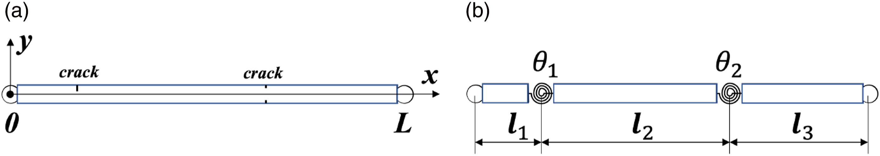
In Figure 1, the patching conditions
17
at a crack point x
i
are described by

In the case of the rectangular cross-section shown in Figure 2, the flexibility can be defined as θ
i
= HC(μ
i
), where C (μ
i
) is a dimensionless local compliance function. Open crack types and crack parameter μ.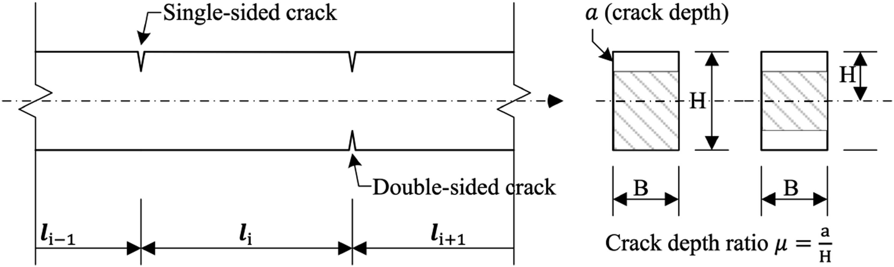
If the crack is double-sided, then the expression for the compliance function C(μ) is

If the crack is single-sided, then

Variational setting
In this Section, we define the Hilbert space V of functions that are suitable to represent cracked beam shapes following.
8
The crucial concept here is the operator
Since it is more convenient to do the theoretical deliberations in non-dimensional variables, we will assume that this is done as indicated. Such a change of variables (using the same symbols to simplify the notation) is accomplished by defining the t-scale variable ω0 and the radius of gyration r by
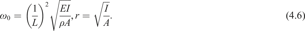
Then the variables are changed using

Let H be the Hilbert space

Let the inner product and the norm in L2 (l
i
) be denoted by (⋅,⋅)
i
and |⋅|
i
correspondingly. The inner product and the norm in H are defined by

Consider the Sobolev space H2 (a, b) on a bounded interval
The linear space is defined as

We interpret u ∈ V as a continuous function on [0,1], such that u (0) = u (1) = 0, with u′ ∈ L2 (0, 1), that is,
Define the inner product on V by

The corresponding norm in V is

Define the operator Recall, that a linear operator A: V → V′ is called coercive, if there exists c > 0, such that

[Ref. 8, Lemma 4.2] Let The main result about
[Ref. 8, Theorem 4.3] Let the domain of (i) If (ii) Let f ∈ H, then equation
Eigenvalues and eigenfunctions
The operator
We summarize these results in the following lemma.
Let (i) There exists an increasing sequence of its real positive eigenvalues (ii) The corresponding eigenfunctions (iii) The eigenfunctions φ
k
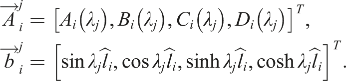
satisfy (iv) The set Two methods for the computation of the eigenvalues are discussed in Ref. 8. One is the Modified Shifrin Method. The other, less efficient, but more straightforward, is the Transition Matrices Method described below. Let us consider the eigenvalue problem Using the patching conditions and the boundary conditions we can obtain recursive equations for The corresponding eigenfunctions are expressed by The eigenfunctions ϕ
j
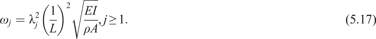
will be used as the mode shape functions of the cracked beam model, as well as for exact closed-form expressions. See Refs. 8 and 9 for the existence, uniqueness, and other mathematical results for the eigenvalues and the eigenfunctions. Relating the eigenvalues λ
j
to physical variables we determine that the natural EB beam frequencies are given by Consider an example of a cracked EB beam of length L = π, the cross-sectional height H = 0.2, with the hinged-type boundary conditions. Crack locations are x
i
= {0.1, 0.2, 0.5, 0.7}L, and the depths are a
i
= {0.5, 0.3, 0.4, 0.3}H. The corresponding flexibilities θ
i
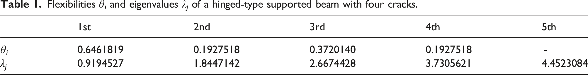
are computed using (3.5). The flexibilities and the first five eigenvalues of the beam are shown in Table 1. The eigenfunctions corresponding to λ
j
are shown in Figure 3. Here the eigenfunctions are normalized in such a way that the maximum of each eigenfunction ϕ
j
is equal to 1.


Flexibilities θ i and eigenvalues λ j of a hinged-type supported beam with four cracks.
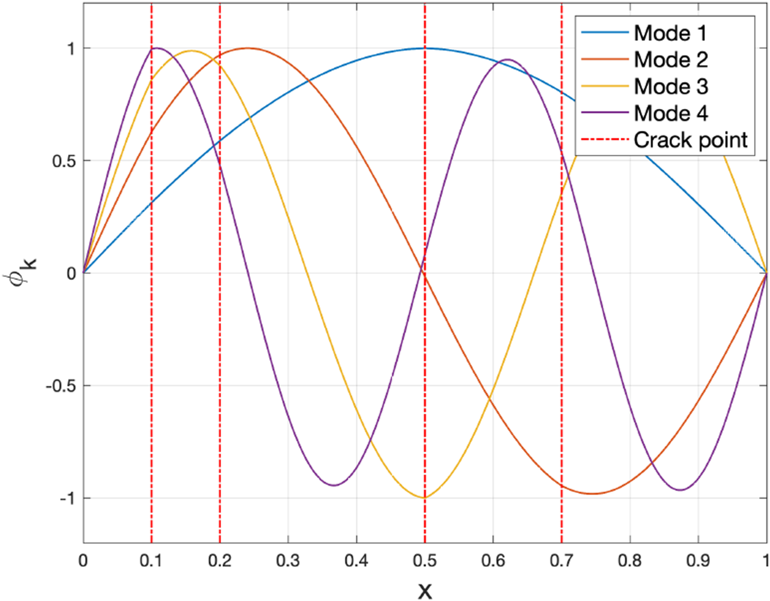
Eigenfunctions ϕ j (j = 1, …, 4) of the hinged-type supported beam with four cracks.
Equations of motion
In this section, we give a brief outline for the derivation of the governing equation (1.2). Full details can be found in our paper. 9
The motion of a classical EB beam with or without cracks is mainly dependent on its bending, while the influence of the axial force is negligible. However, this influence cannot be ignored for an extensible beam (arch), since a large deflection causes an axial force. Accordingly, the potential energy for a cracked extensible beam has two components: U = U b + U a . Here U b is the bending potential energy, and U a is the potential energy due to the axial force N.
To derive the governing equations for beams and arches, we use the Extended Hamilton’s Principle, which accommodates non-conservative forces. The Principle states that the motion y = y (x, t) of the system gives a stationary value to the action of the system, that is, to the integral
Thus, (6.18) becomes
The traditional way of expressing the fact that the motion of the system gives a stationary value to the functional I defined in (6.19), is to say that its variation δI = 0. This can be accomplished as follows.
Given a suitably chosen function η, the directional derivative I′(y; η) is defined by
Functional I has a stationary value at y, which means that all such directional derivatives are equal to zero. Doing so, we arrive at the following main result
[Ref. 9, Theorem 6.1]. Equation Here ∂U
b
:V → V′, and To transition from a variational formulation to a classical one, we have to assume a better regularity of the subdifferential arguments. Basically, we require that function y has a sufficient smoothness to allow for one or more integration by parts. Several such examples are given in Section 8 of Ref. 9. In particular, in the case of a cracked extendable beam (arch), equation (6.21) takes the following “classical” non-dimensional form see [Ref. 9, equation (8.8)]. This equation is also referred to as describing the weak arch damping motion. The quotes are used to note that (6.22) contains delta functions. Transitioning back to physical variables gives equation (1.2) The deflection y leads to axial elongation, and the tensile force S1 is generated by it. Note that S1 is not accounting for the axial force at the cracks. It is basically derived by the assumption that the stress caused by the elongation is uniformly distributed in the cross-section. Since the stress by the elongation is concentrated near the crack location,
12
the tensile force will be reduced in proportion to the cross-sectional area reduced by the crack. So, to account for the cracks, we introduce a reduction ratio α, and the axial force N is defined as Concerning the boundary conditions, we consider them to be either of the hinged (pinned) type In this paper, we will work with equations (6.22) and (6.28). The initial axial force will be assumed to be zero, that is, we let β = 0. In particular, if α = 1, then (6.28) becomes Binici
29
introduced a method for determining natural frequencies and mode shapes accounting for the axial force. However, they dealt only with the case of the initial force S0 in (6.25). In Ref. 29, the natural frequency is decreased when the axial force is compressive and it is increased when the force is tensile. In fact, the frequency of a cracked EB beam is smaller than that of the intact EB beam when the axial force is not introduced. However, the frequency of the cracked beam with the tensile force (β > 0) may be higher than that of the intact beam as shown in Figure 4. Also, it depends on the magnitude of the tensile force. Furthermore, the axial force is changed under large deflection. Here we investigate the case of β = 0 and α ≠ 0, which is different than in Ref. 10, because the axial force is not assumed to be constant. The expectation is that the natural frequency increases when so does the deflection y, because the force N contains only a tensile force due to the deflection.


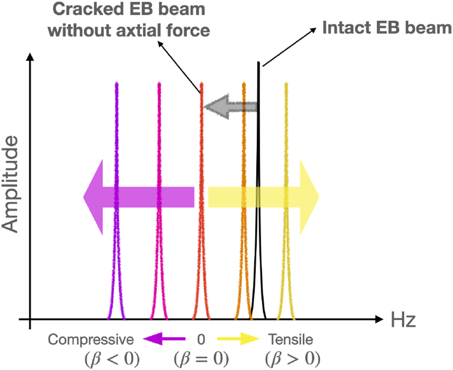
Frequency of cracked EB beam as a function of the initial axial force β.
Eigenfunction expansion of governing equations
In this section, we deal with the governing equation of a multi-crack extensible beam given in (6.22). Its eigenfunctions ϕ j are represented by (5.16). They satisfy the patching conditions (3.3), and the boundary conditions (6.26)–(6.27).
Assume that the solution y and the load p in (6.22) can be expressed as
Here, the external force p (x, t), represented as a series function, consists of the eigenfunction ϕ j (x) and the coefficient p j (t). It represents the applied load as a linear combination based on the natural mode functions. In this study, we address equations derived by decomposing the applied forces into mode-based loads in order to predict the changes in natural frequencies and dynamic responses of the cracked extensible beam.
Following Eigenvalues and eigenfunctions, we have
Let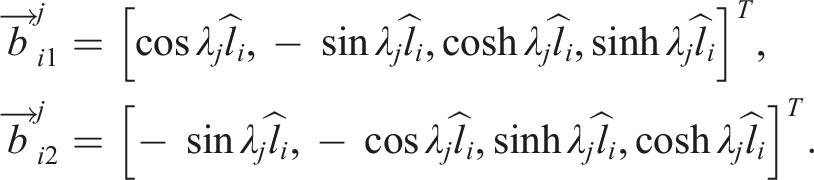
Then, we get
Since the eigenfunctions ϕ
j
are orthogonal, the inner product of ϕ
j
and ϕ
k
is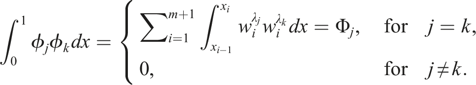
Substitute the series for y and p into (6.22) and take the inner product of (6.22) with ϕ
n
to get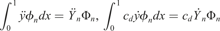
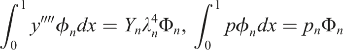

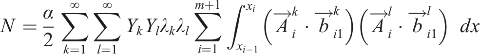
Using these inner product terms, we find the governing equations

Applications and numerical results
In this section, we consider examples of an extensible beam with cracks using (7.33), and investigate the dynamic characteristics of the beam depending on the initial condition and the external force. In the case of the EB beam with cracks, the natural frequency of the beam can be calculated by (5.17) (see the eigenvalue problem in Eigenvalues and eigenfunctions).
The influence of the axial force due to the deflection leads to the nonlinear governing equations as shown in (7.33). Therefore, the vibration of the nonlinear system is different from the linear system, and it depends on the initial conditions and the external force.
In this section, we will investigate these differences using numerical examples for single-crack beams, five-crack beams, and other multi-crack beams. We evaluate the displacement response, axial force, and the natural frequencies depending on changes in the crack parameters and other conditions. Here all the examples are for undamped systems, and the frequency responses are obtained using the Fast Fourier Transform (FFT).
Free undamped extensible beam with a single crack
Consider the single cracked model with the simple support introduced in Ref. 2. Material properties are the elastic modulus E = 2.0 × 10¹¹ N/m2, and the density ρ = 7, 800 kg/m3. Geometric parameters are the beam length L = 20m, the cross-sectional height and the width H = B = 0.2 m, the crack location l1 = 0.4 L, and the depth is a = 0.5H. Here, p k = 0, and (3.5) is adopted for the crack compliance function.
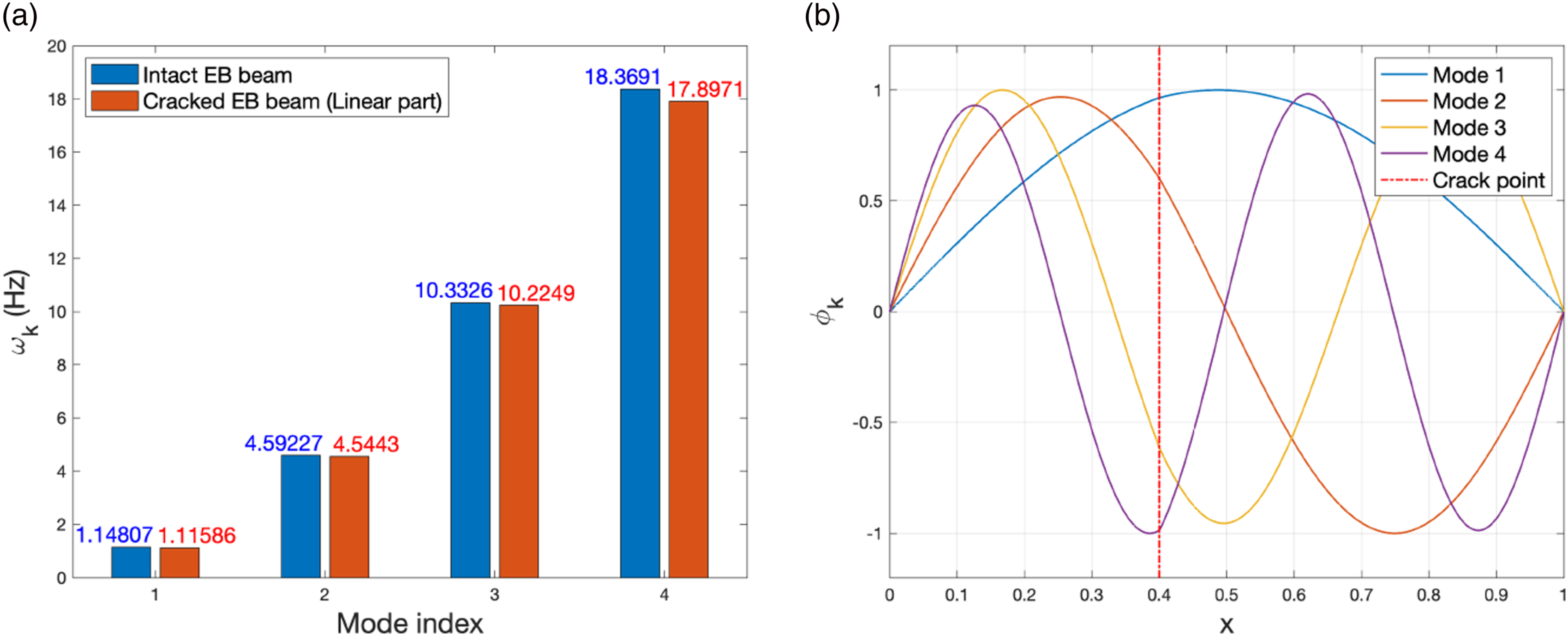
From the eigenvalue problem of the target model, we can calculate the natural frequencies ω
k
and draw the mode shapes ϕ
k
corresponding to the eigenvalues as shown in Figure 5. Four mode shapes and the crack point are presented. They are normalized so that the maximum value of |ϕ
k
| equals 1. The results for natural frequencies and modes are consistent with those in Ref. 2. Natural frequencies ω
k
and eigenfunctions ϕ
k
of a single-crack beam (linear system, k = 1, …, 4). (A) ω
k
, (B) ϕ
k
.
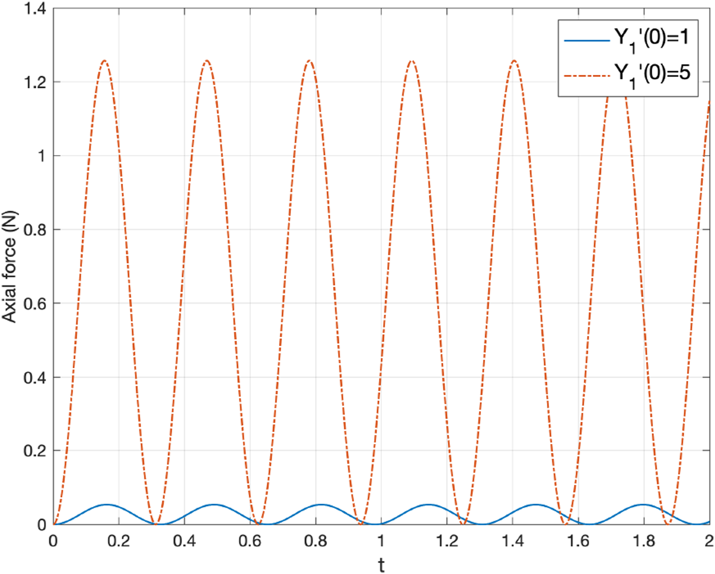
Now consider the first mode ϕ1 with different initial velocities
Displacement Y1 is shown in Figure 6, where Figure 6(A) is for Displacement Y1 of a single-crack extensible beam (Y1(0) = p1(0) = 0). (A) 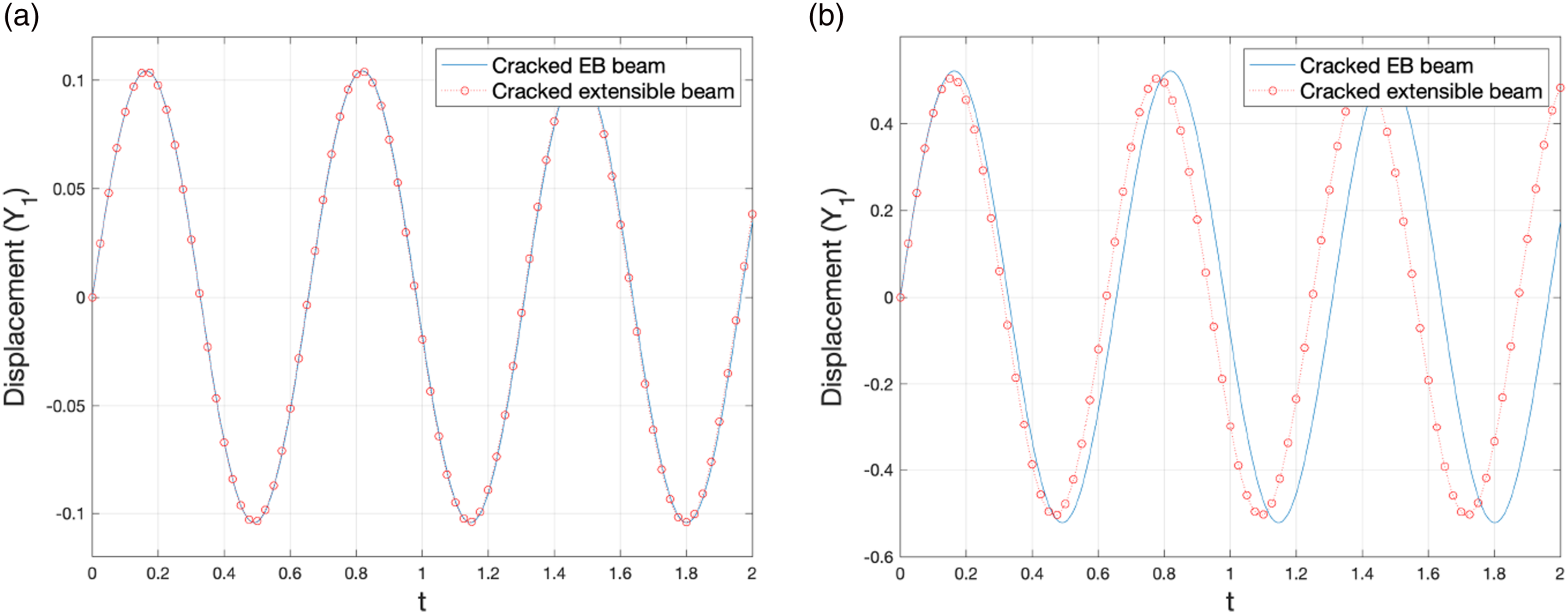
This aspect can be more easily understood by looking at the change in the axial force N, as shown in Figure 7. The axial force depends on the deflection, and the effect of the axial strain energy caused by the vertical deflection is well reflected in shortening the oscillation period. Figure 8 shows that the difference between the magnitudes and the periods of the two axial forces is very significant. Axial force N in a single-crack extensible beam (Y1(0) = p1(0) = 0). (A) Axial forces N in a single-crack extensible beam with Y1(0) = p1(0) = 0 for two different initial conditions: 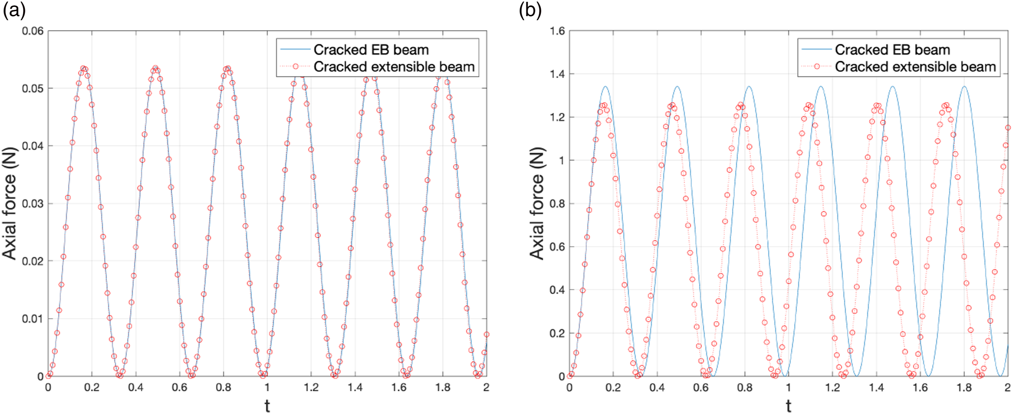
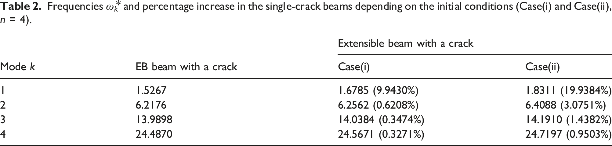
Now let us consider the higher order mode functions with the following initial conditions. • Case(i) Y
k
(0) = p
k
(0) = 0, • Case(ii) Y
k
(0) = p
k
(0) = 0,
where n is the number of mode shape functions used in the analysis.
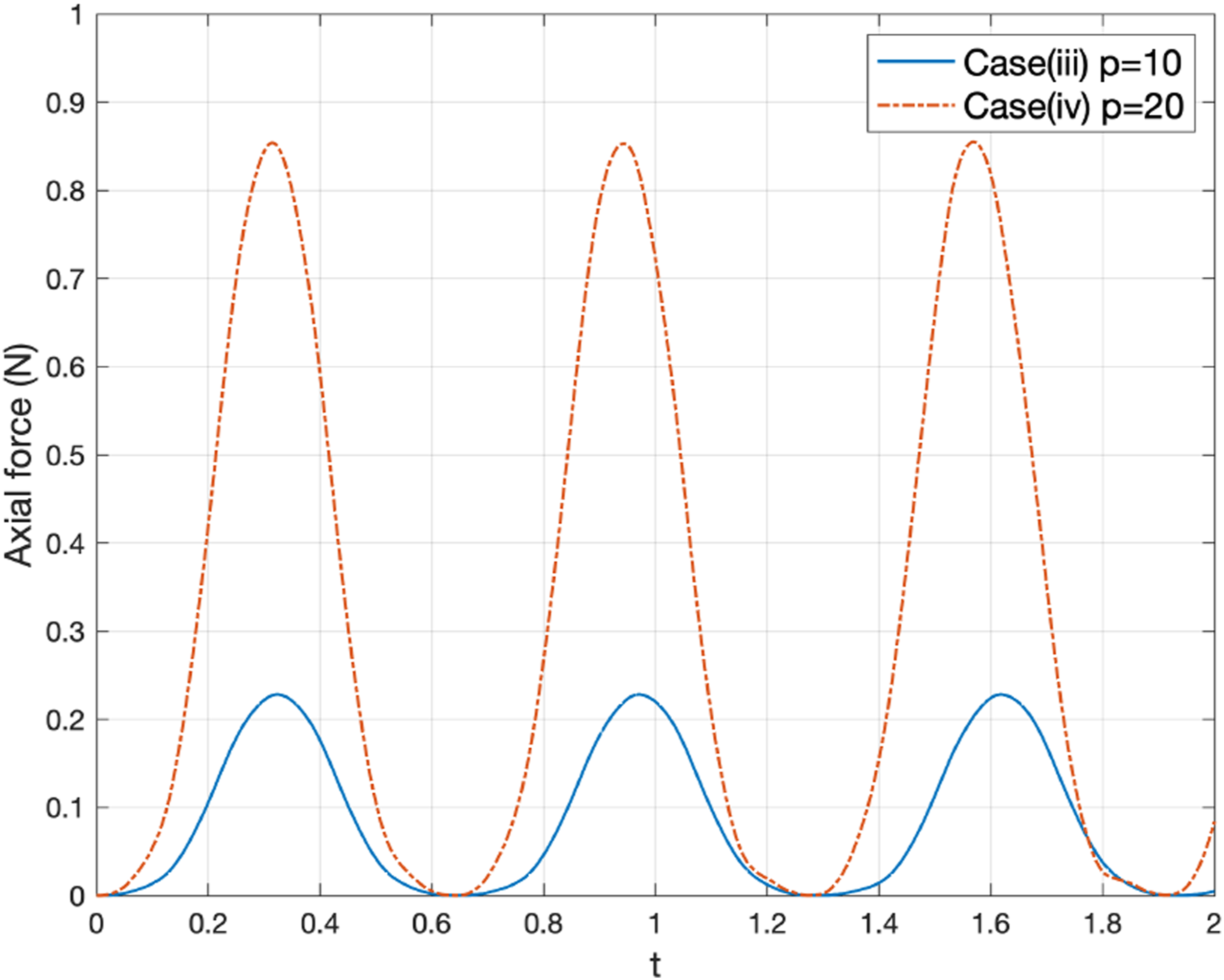
In Case(i) and n = 4, the analysis results are as shown in Figure 9. The displacement and the axial force are presented in Figure 9(A) and (B). Observe the complicated shape of the axial force, and that it is mainly influenced by the first mode. Displacement 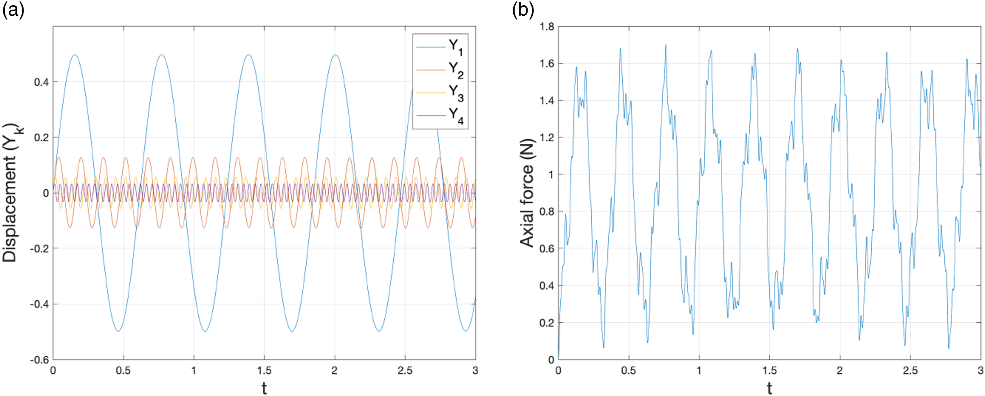
For a comparison with Case(i), Case(ii) is considered under the same conditions, except that the conditions Displacement 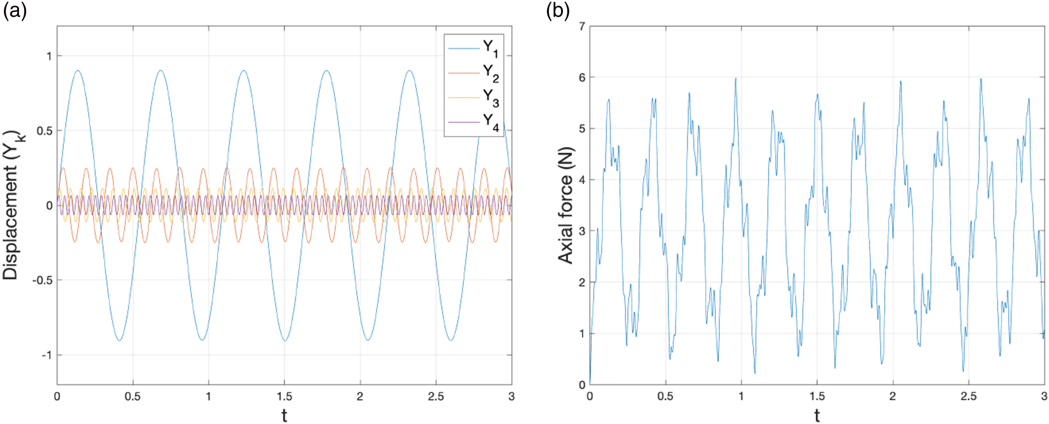
The effects of the change in the axial force on the natural frequencies of a cracked beam are shown in Figure 11. In it the normalized frequencies Frequencies 
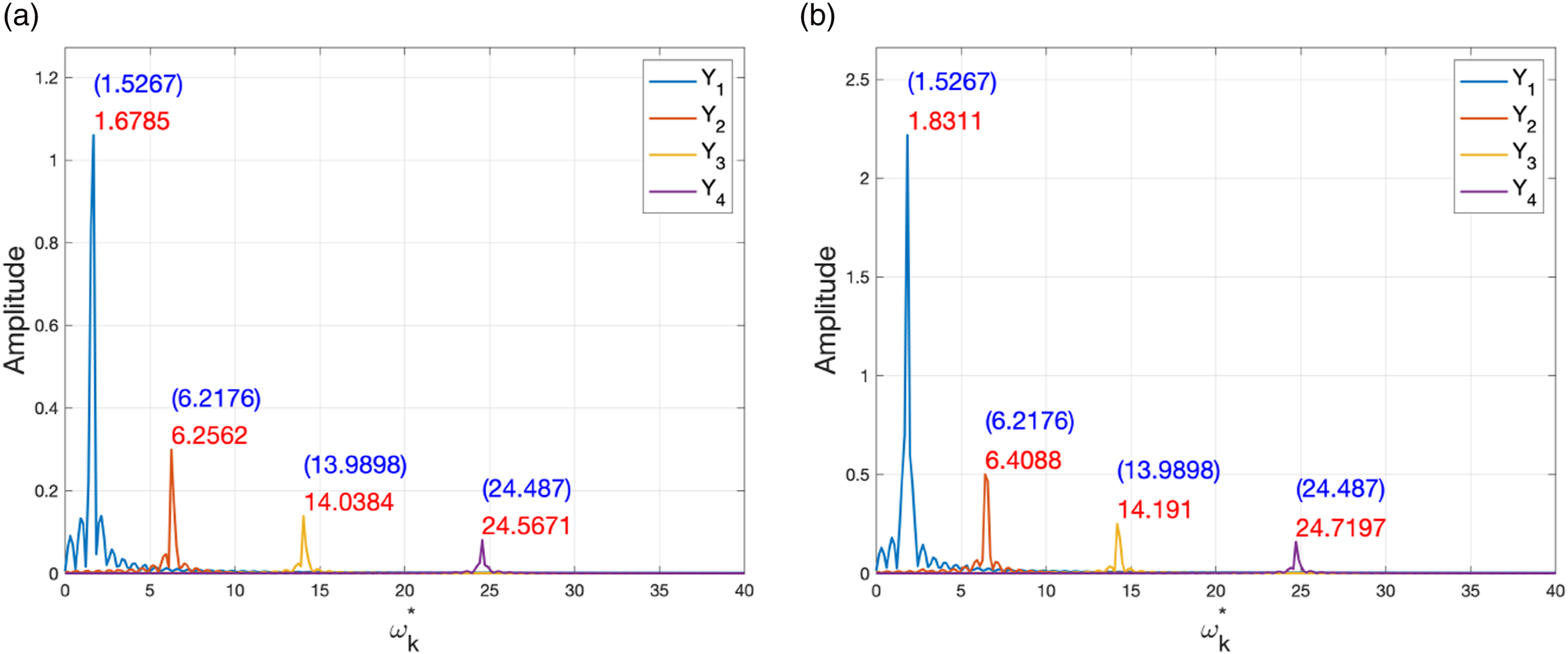
Figure 11 shows that the extensible beam has higher frequencies than the EB beam in both cases. However, the differences are more pronounced in Case(ii) than in Case(i). To be clear, the frequencies depend on the magnitude of the transverse deflections.
Frequencies
Forced undamped extensible beam with a single crack
Consider two cases for a cracked extensible beam with the external force p
k
. Geometric, material, and boundary conditions are same as in Example 8.1. The cases are • Case(iii) • Case(iv)
where n = 4 is the same as in the previous examples. Let α = 1.0.
The displacement and the axial force for Case(iii) are shown in Figure 12. Note that max |Y1| > 0.2, and the influence of other modes is small. In this case, the axial force N satisfies the nonlinear system for the extensible beam. However, it is similar to the result for the linear system (EB beam), because the influence of the deflection by the external force p
k
is small. Displacement 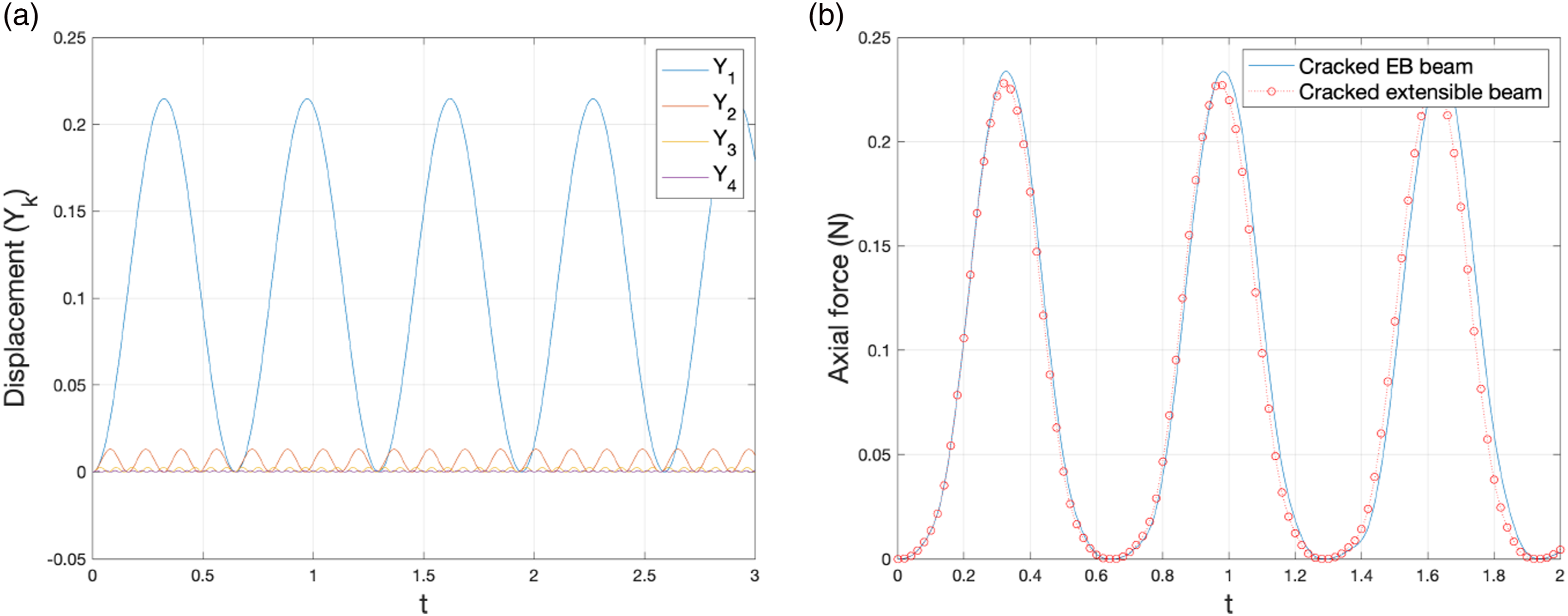
In order to show the effect of the external force, we analyze the cracked beam of Case(iv), and let p
k
be twice that of the previous case. The displacement is also approximately doubled to a value of over 0.4. Now we can observe the difference between the linear and nonlinear cases resulting from changing the axial force (see Figure 13). It shows that the larger is the deflection caused by the external force p
k
, the larger is the change in the axial force N. The magnitude of the axial force is about four times bigger as shown in Figure 14. Displacement Axial forces N in the single-crack extensible beam with external force. Cases (iii) and (iv), n = 4.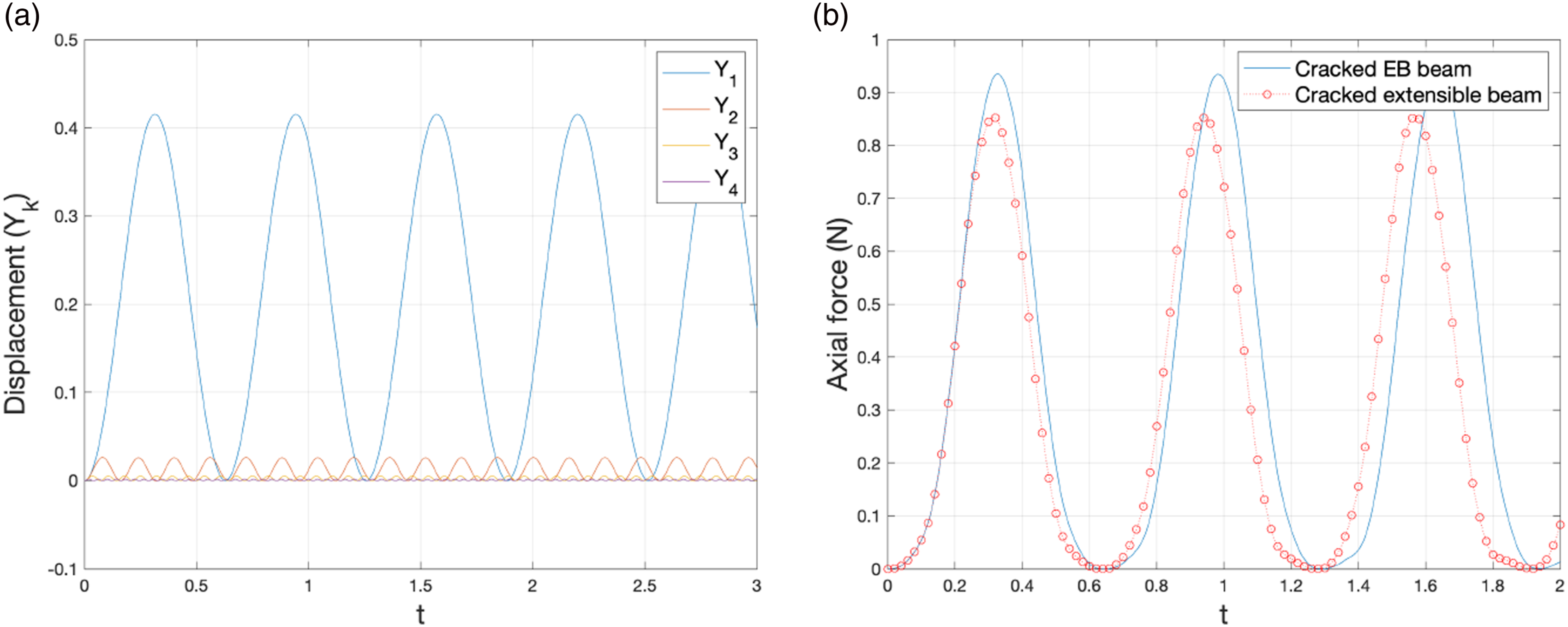
The corresponding frequencies are shown in Figure 15. In order to compare the cracked EB beam with the cracked extensible beam, the frequencies Frequencies Frequencies 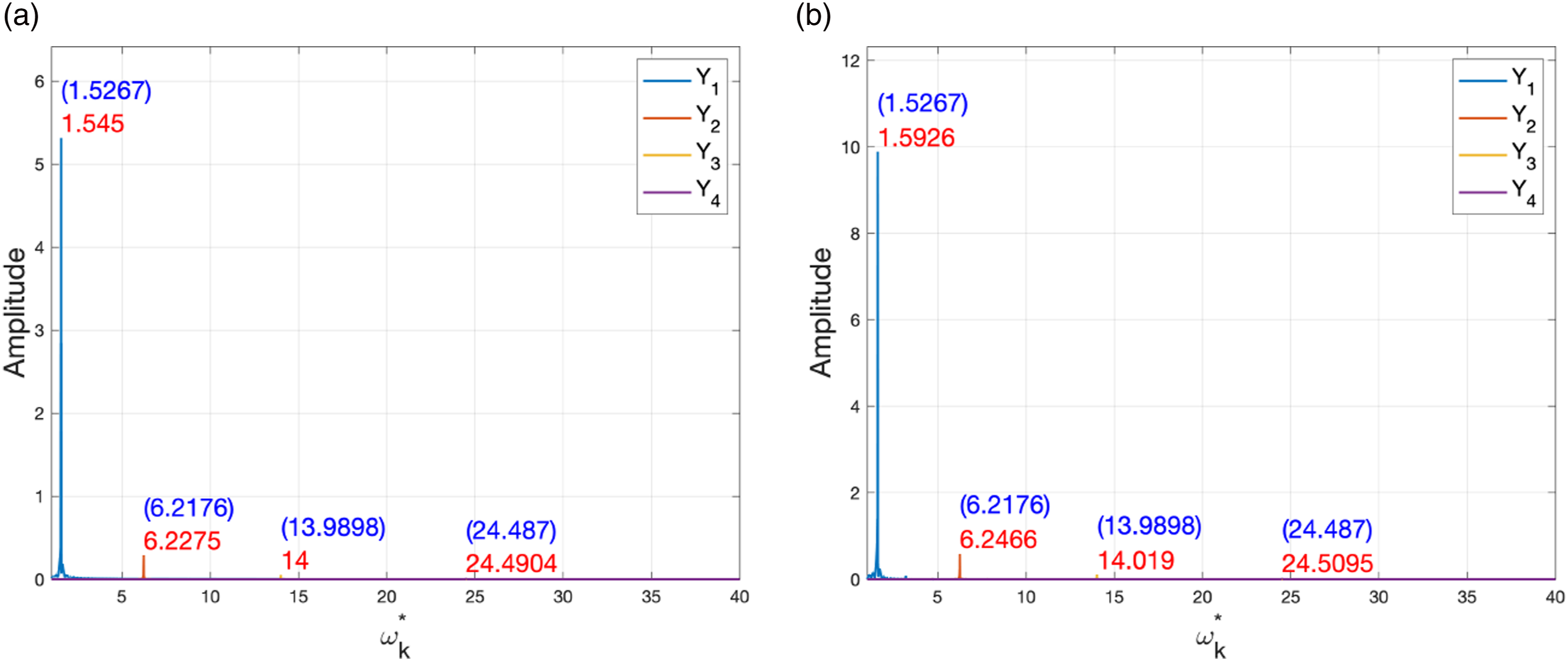
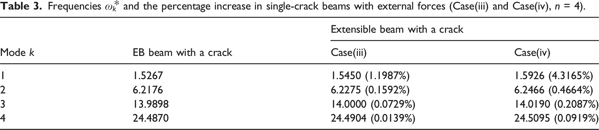
The frequency of the first mode in the extensible beam model is increased (as compared with the EB beam) by about 1.2% in Case(iii), and by 4.3% in Case(iv). However, for other modes, the effect is not so significant, because the maximal displacement of the first mode is larger than that of the other modes. That is, the same reason as in the previous frequency comparison. Doubling the external force between Case(iii) and Case(iv), the frequency of the first mode is nearly quadrupled, but not for other modes. As can be seen from these results, the relationship between the transverse load and the axial force due to the transverse displacement is not linear.
Free undamped extensible beam with five cracks
In this example, we compare results for the hinged and clamped boundary conditions (see (6.26) and (6.27)). The single-crack example in Free undamped extensible beam with a single crack was focused on the effects on the deflection according to the initial conditions, that is, the initial velocity and the external force, but in this example, we consider two different boundary conditions, while keeping the other parameters the same.
Deflections of the beam with the hinged support at both ends are generally larger than for the beam with clamped boundary under the same conditions. We will demonstrate the validity of the proposed equations with the cracked beam example by obtaining these results.
The settings are as follows: the beam has five cracks located at x i = {0.1, 0.15, 0.2, 0.5, 0.6}L. The cracks depth ratios are μ = {0.5, 0.3, 0.3, 0.5, 0.3}. Material and geometric properties are the same as in the single-crack example, that is, E = 2.0 × 10¹¹ N/m2, ρ = 7, 800 kg/m3, L = 20m, H = B = 0.2 m, and α = 1.0.
In Figure 16, we show the first four mode shape functions. Figure 16(A) is for the hinged support, and Figure 16(B) is for the clamped one. The crack points are also presented in the figures. The mode shape functions are normalized to have max |ϕ
i
| = 1. Mode shapes (eigenfunctions) ϕ
k
of a five-crack extensible beam, k = 1, …, 4. (A) Hinged (B) Clamped.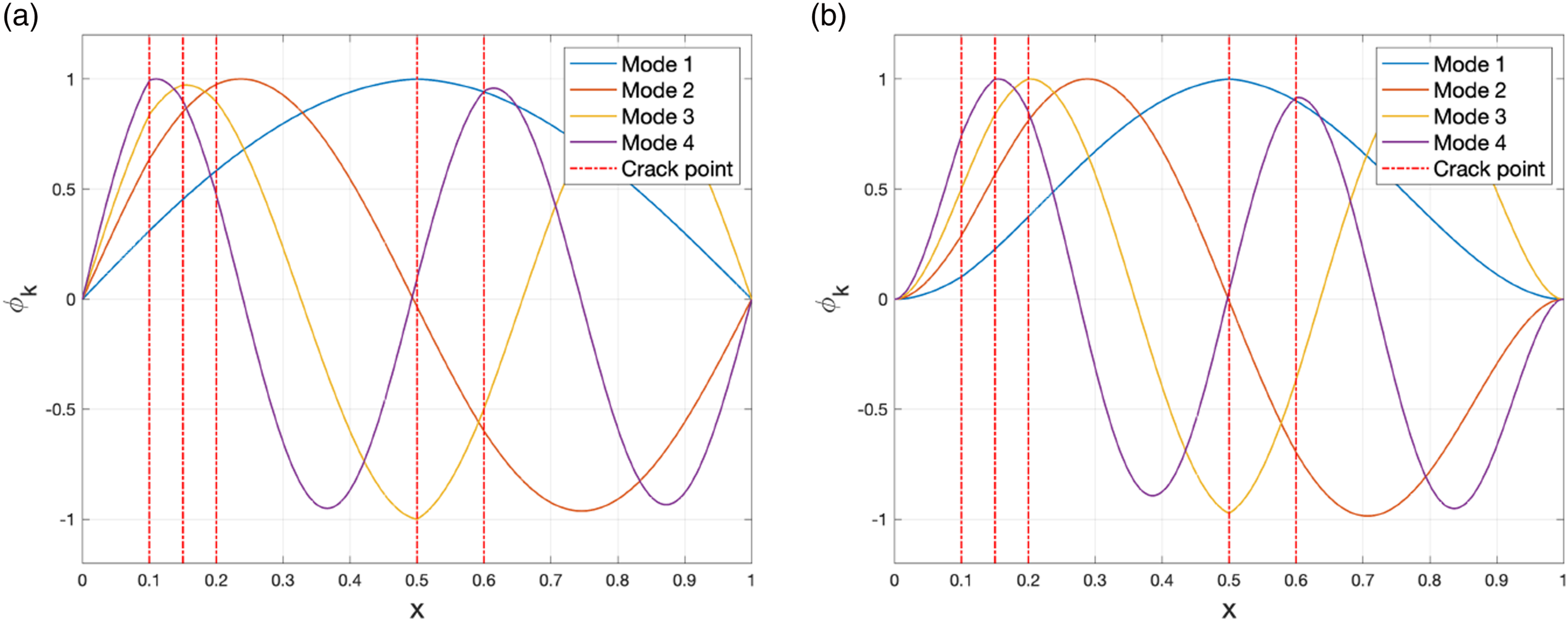
The notable difference between 16(A) and 16(B) is in the boundary conditions. Let us examine the first crack point for the hinged model. The fourth mode shape function has a visible slope discontinuity at this point. Of course, this effect is also present in other modes, but to a much smaller degree. The slope discontinuity is also somewhat visible for the first and the third mode functions at the forth crack point x4 = 0.5 L.
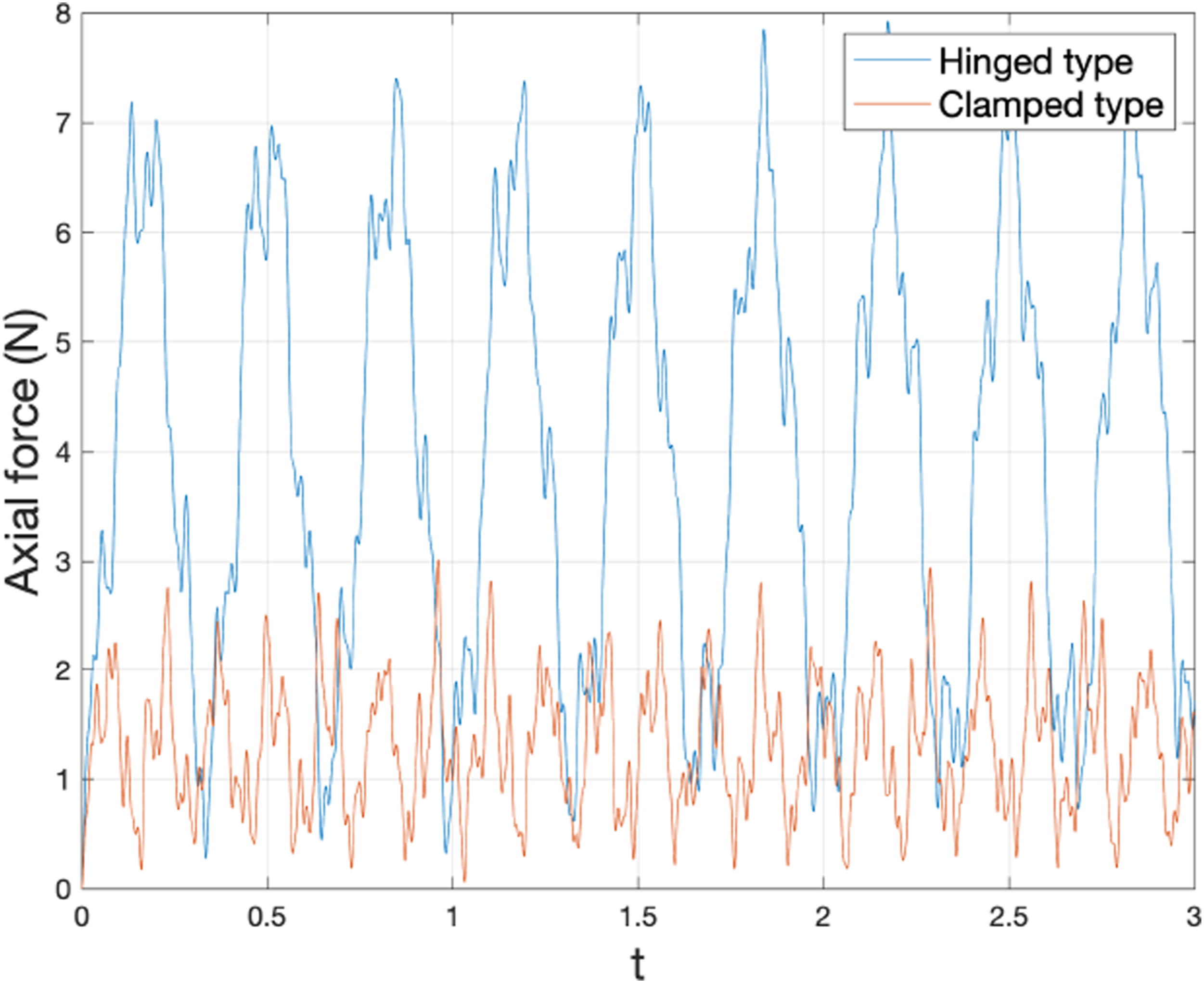
The displacements for the hinged and the clamped boundary conditions are shown in Figure 17. Here the initial conditions are the same as in Case(ii) of the single-crack example. As it was mentioned, the maximum |Y
k
| for the hinged case is larger than the one for the clamped case. This is shown in Figure 17. We observe the corresponding change in the axial force, as shown in Figure 18. That is, in the hinged case, the axial force N is larger than the one in the clamped case. Displacements Axial force N in a five-crack extensible beam (Case(ii), n = 4).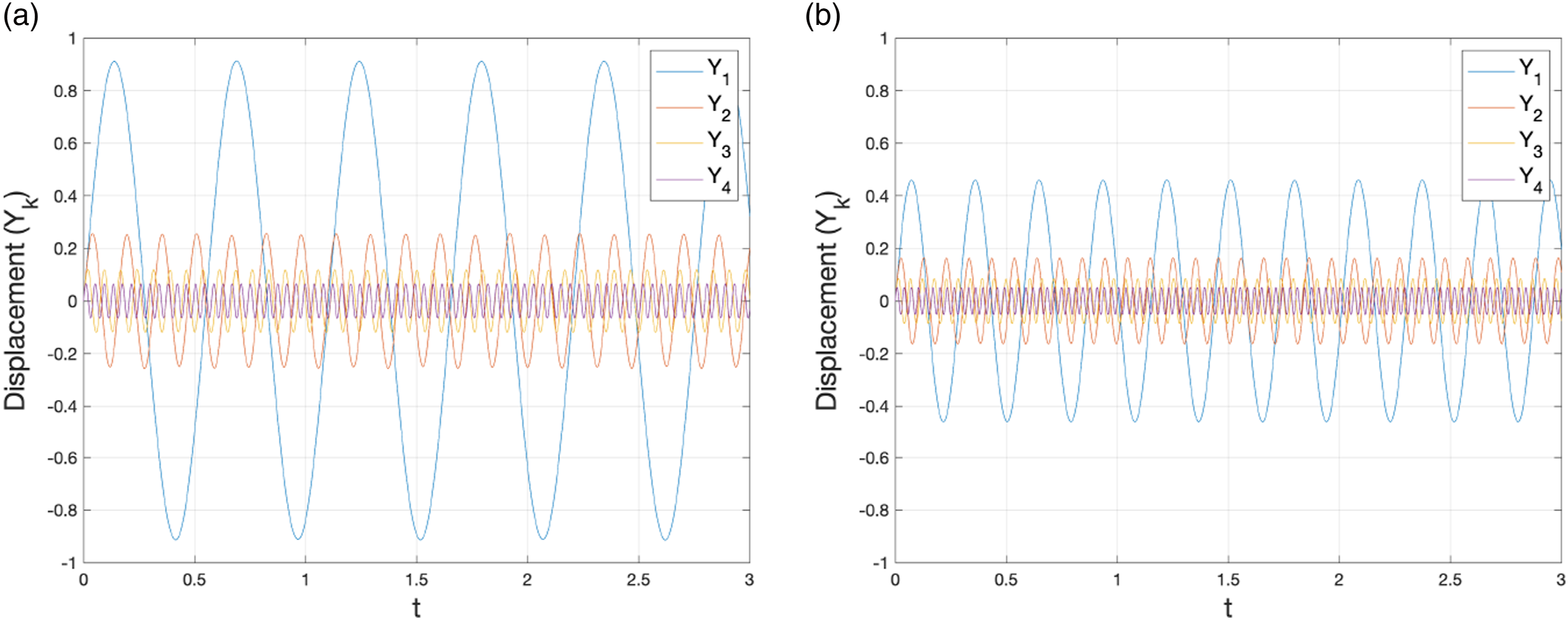
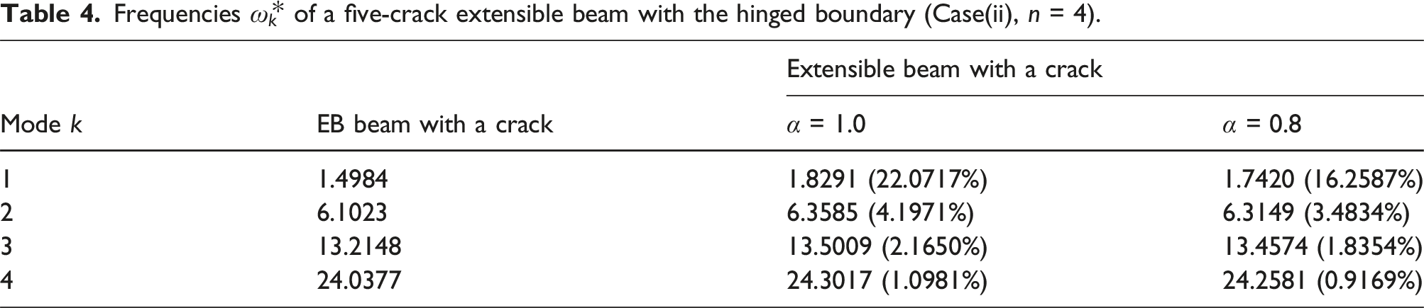
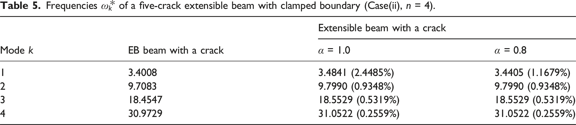
Furthermore, we compare the frequencies Frequencies 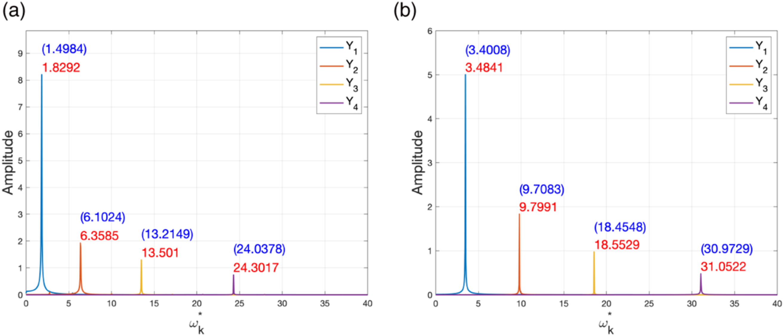
The result shows that the corresponding frequencies of the cracked extensible beam are higher than that of the cracked EB beam for both boundary conditions. Also, the frequencies for the hinged boundary case are lower than that of the clamped boundary case. This is also true in all the previous examples.
Frequencies
Frequencies
Extensible beam with multiple cracks
In this subsection, we consider the first mode shape and its vibration of an extensible beam with cracks. Its material and geometric properties are the same as in the single-crack example. The beam has the hinged-type boundary conditions.
We investigate the dependency of the beam frequencies on the crack position x c , its depth ratio h c = μ, and the reduction ration α. The axial force N is as in (6.25). Observing the vibration of the first mode of the beam we find its frequency ranges.
Figure 20 shows the first mode frequency First mode frequency 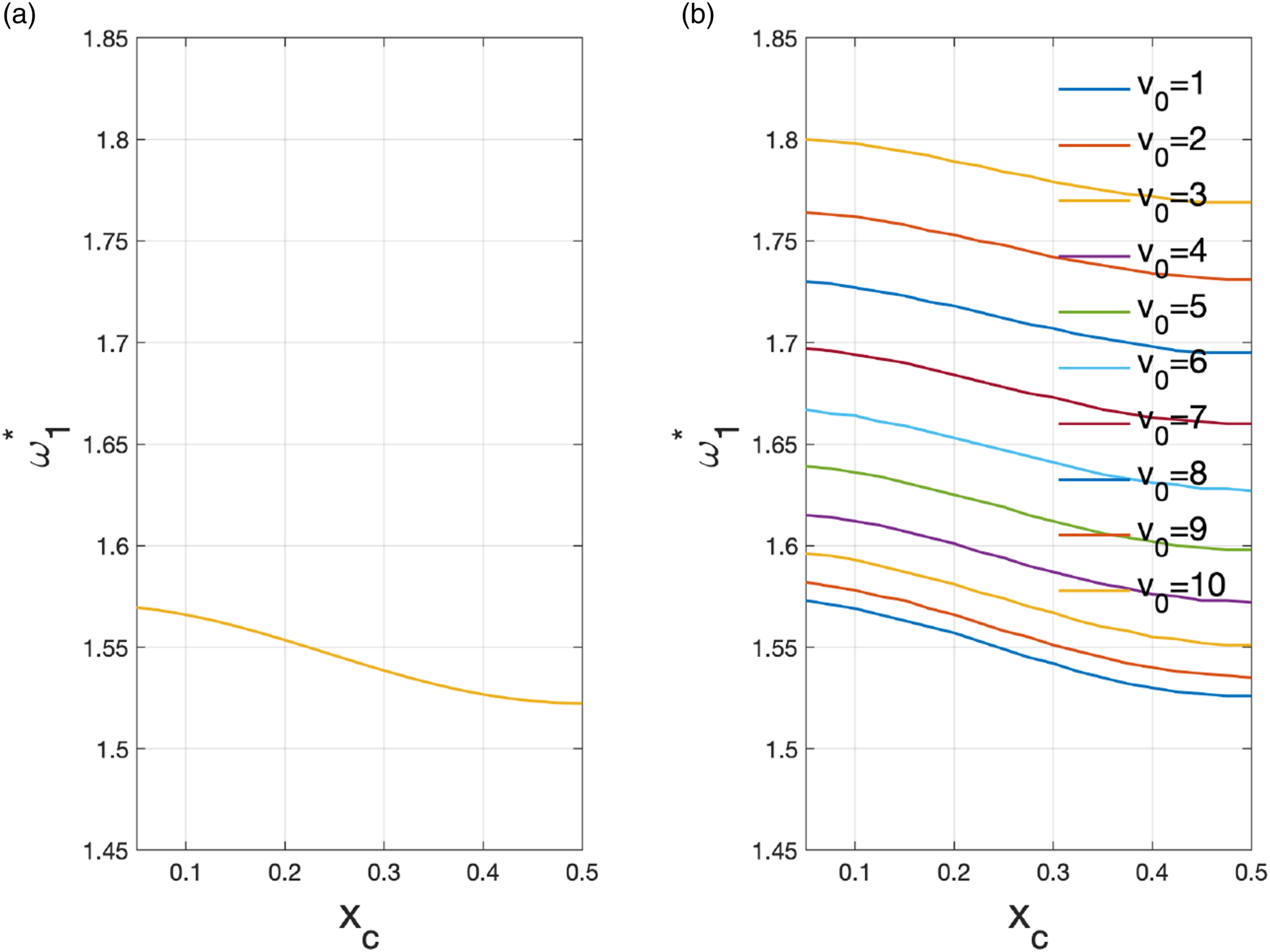
Figure 21 shows the first mode frequency First mode frequency 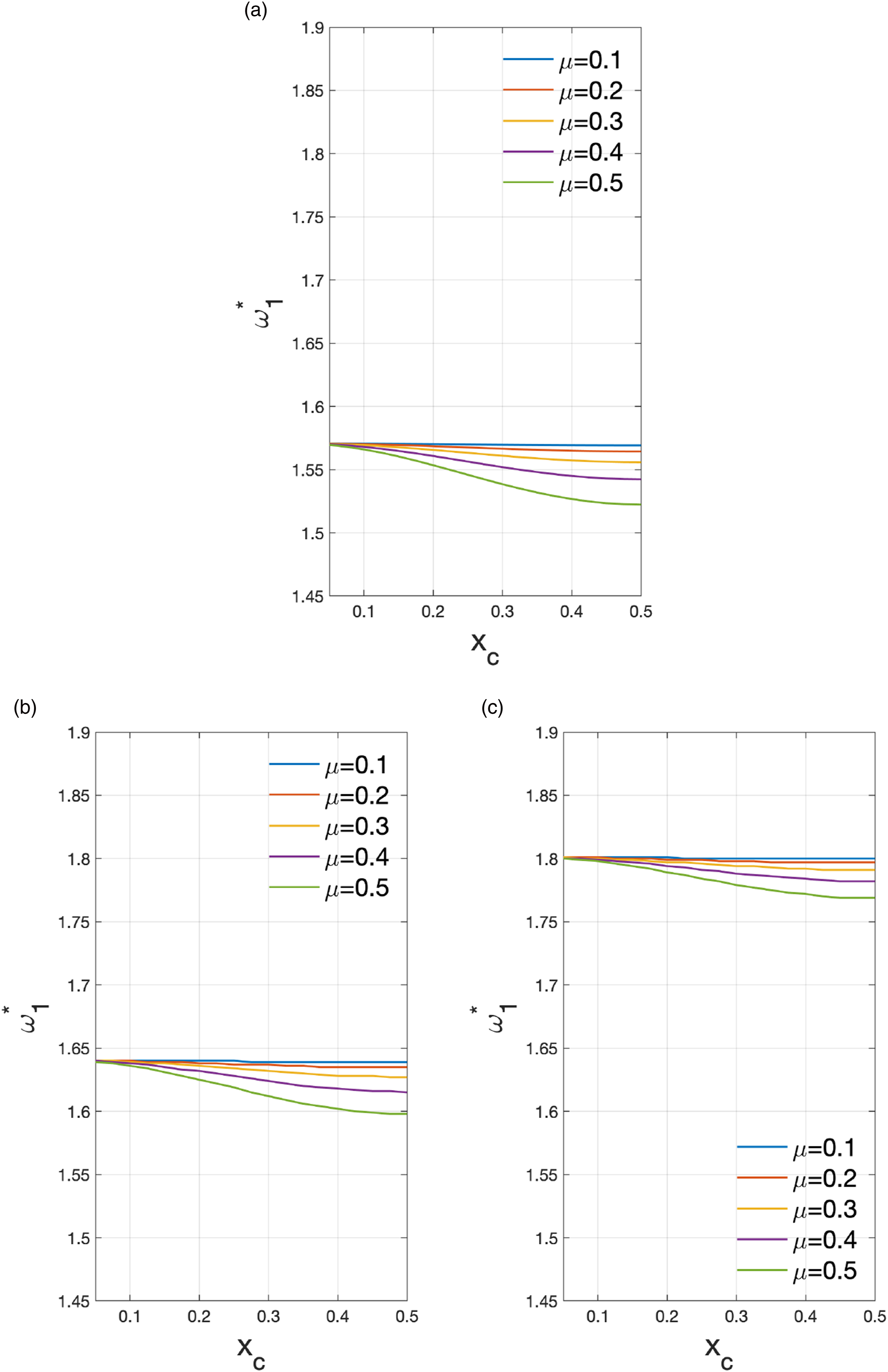
Now we compare a cracked beam with the corresponding intact beam. Figure 5(A) shows that the natural frequencies ω
j
of the cracked beam are smaller than for the intact one. Figure 20 shows that the frequency
Thus, the frequency is changed by the tensile force due to deflection in either case where the beam is cracked or not. Figure 22 shows that if the beam is subject to the axial force, then its frequency approaches the one for the EB beam when α = 0, and the extensible beam when α = 1. Also, from Figure 21, we can see that cracked beam’s frequency is smaller than the one for the intact beam. The frequency comparison for EB beam and extensible beam with tensile axial force. (A) μ = 0.3, (B) μ = 0.5.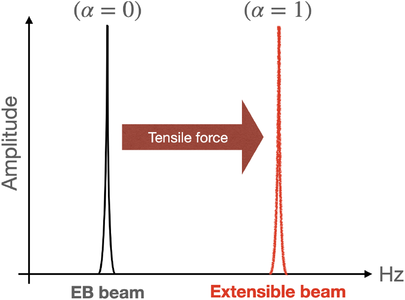
If a beam is in the state where the axial force’s influence cannot be ignored, then we need to do a different comparison. So, let the frequencies of the linear (EB beam) and nonlinear model (extensible beam) without the cracks be
The comparison results for the cracked beam are in Figures 23 and 24, for v0 = 5 and v0 = 10, respectively. We used the depth ratio μ = 0.3 for (A), and μ = 0.5 for (B) in the figures. We can see that the frequency of the cracked beam is smaller than the one for the intact beams, whether it is an EB beam or an extensible beam. Also, the frequency of the extensible beam is higher than the one of the EB beams because the axial force N (due to deflection) has a positive value, recall (6.29) in Equations of motion. Frequency ratios Frequency ratios 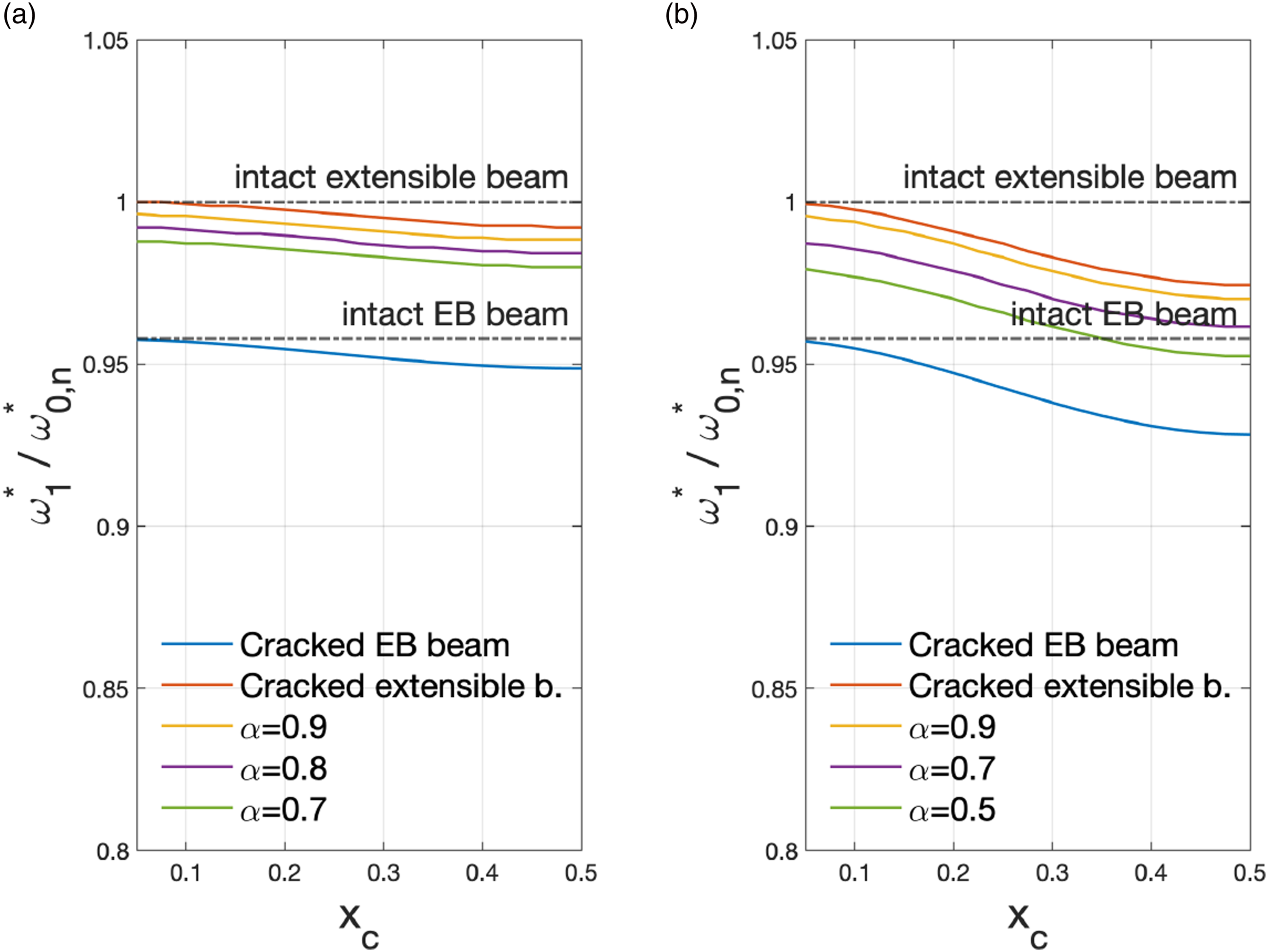
Now we investigate the influence of the area reduction ratio α using Figures 23 and 24. Suppose that α < 1.0, that is, the effective cross-sectional area due to cracks is smaller than A. Then the frequency of the cracked extensible beam is smaller than the one of the intact beam. The frequencies have a hierarchical decreasing pattern, as shown in the figures. It seems to be
The frequency of the cracked extensible beam is shown in Figure 25. It is determined by the axial force N due to deflection, and α which depends on crack parameters. The frequency for such a beam is smaller than that for the intact extensible beam. Also, it shows that it is bigger than when the axial force is absent. Figure 23(B) shows that if the deflection is small and the crack is deeper, then the frequency can be smaller than that for the intact EB beam. Note that the frequency depends on the crack parameters. Comparison of frequencies between intact beam and cracked beam, accounting for the axial force and α.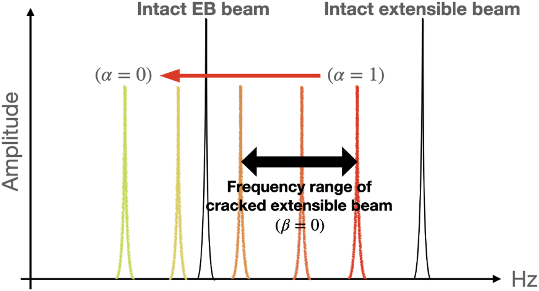
Finally, in Figures 26–28, we study the effect of the number of cracks m (crack number), and the crack depth ratio μ on the beam frequency. The figures were made for the [0, 0.5] depth ratio range, and [0,20] crack number range. In the figures, Frequencies Frequency ratios Frequency ratios 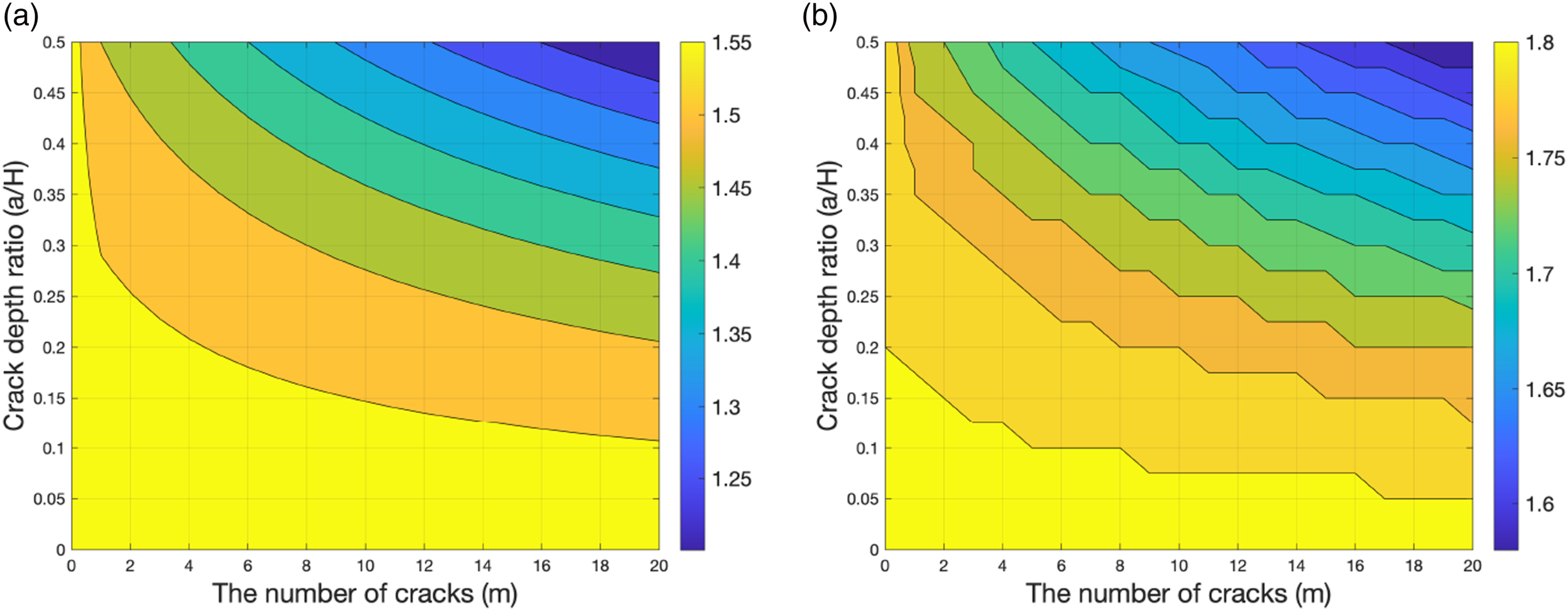
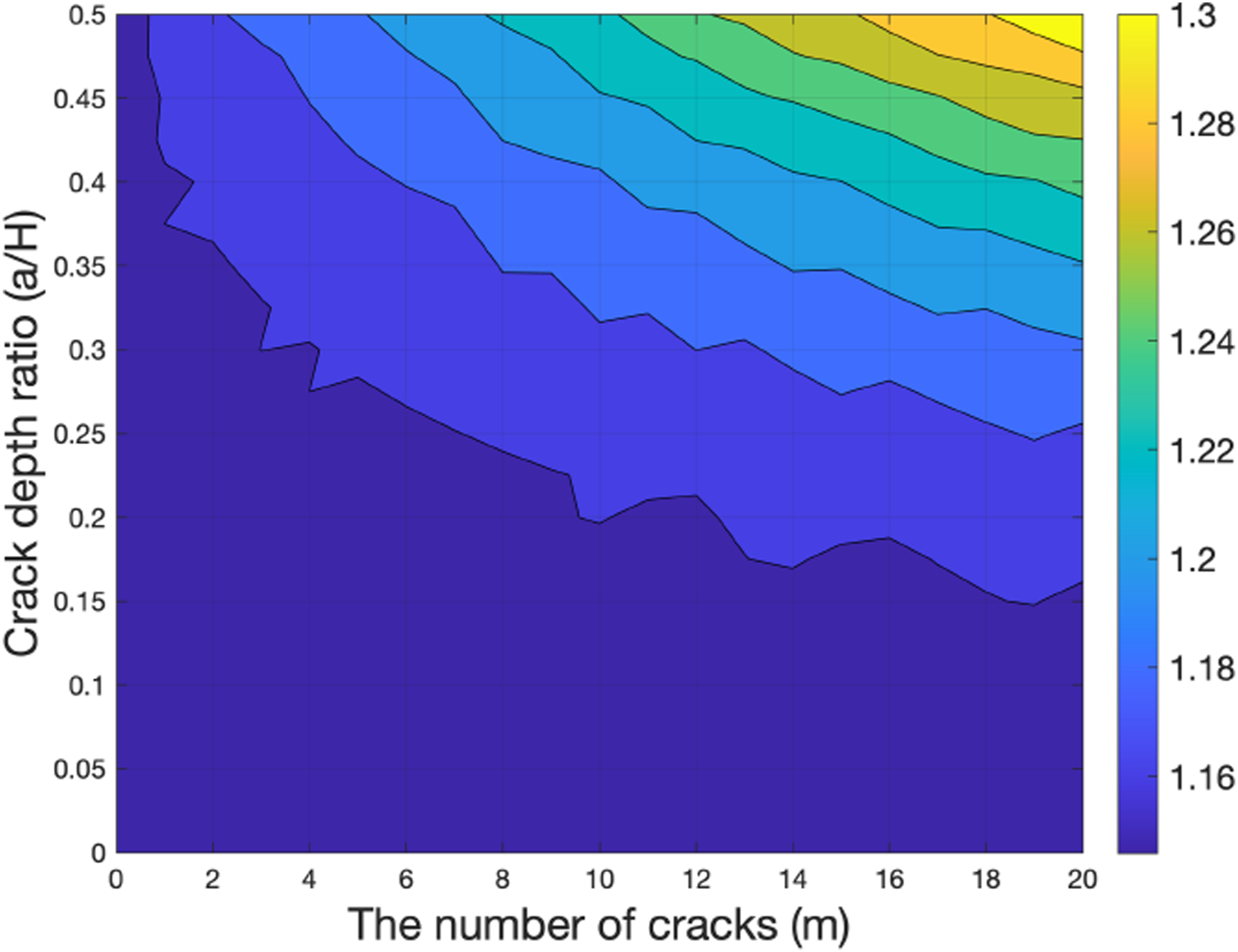
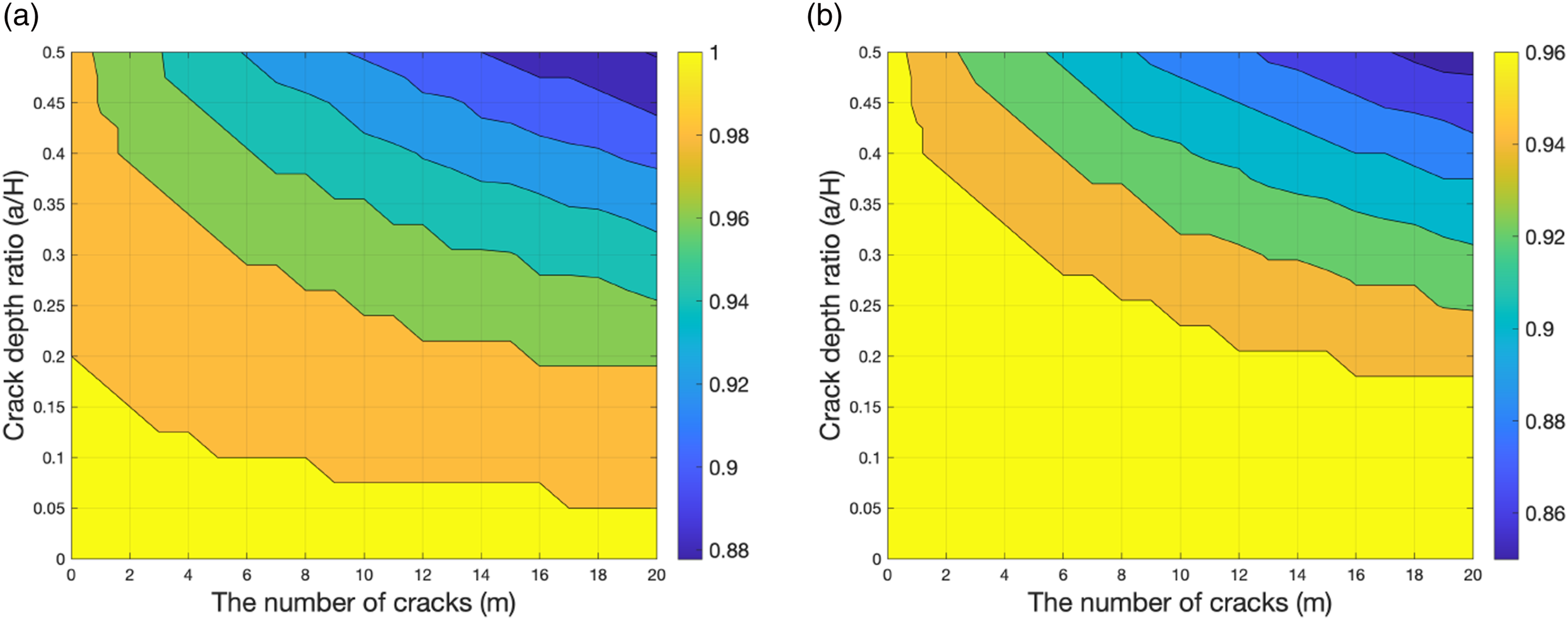
Figure 26 shows that the frequencies decrease with the increase in m and μ. Both the EB beam (Figure 26(A)) and the extensible beam (Figure 26(B)) show the same pattern. In the given parameter range,
From the Figure 27, the ratios of
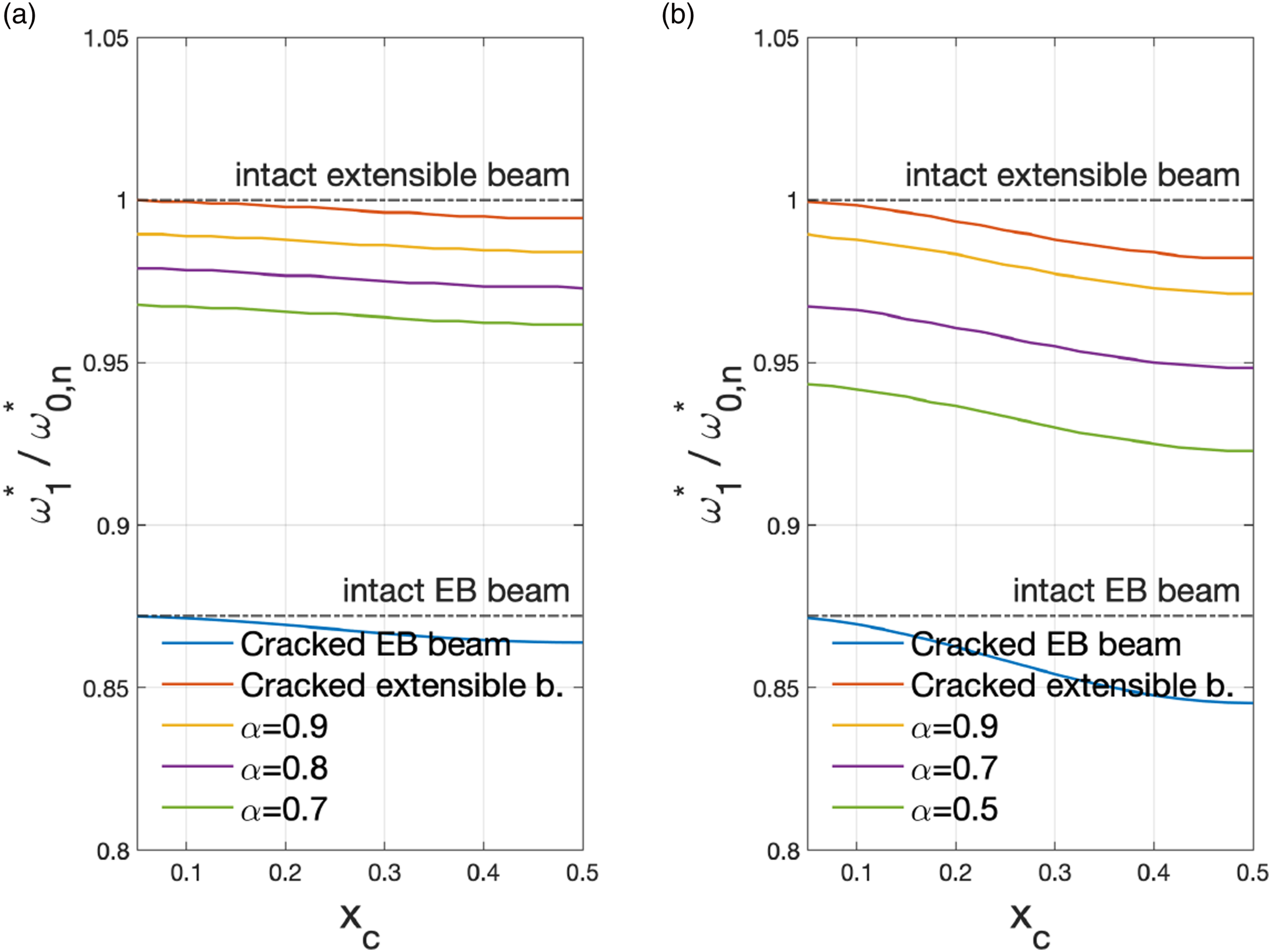
Figure 28 shows the comparison of a cracked and an intact extensible beam. Here α = 1.0 in Figure 28(A), and α = 0.8 in Figure 28(B). The frequency ratios are in the range of 0.877 − 1.0 as shown in Figure 28(A). If α = 0.8, then the range is 0.85 − 0.977, as shown in Figure 28(B). In both cases, the frequency
Conclusions
Investigation of a long-span beam (shallow arch) has to account for the effects of its large deflections. It manifests itself as an axial force term appearing in the governing equation. In such situations, we refer to the beam as an extensible beam. When the beam has multiple cracks, it is not easy to derive and solve equations for it’s the vibration. In this paper, we propose a modified cracked extensible beam considering the reduced cross-sectional area factor. We study its vibration characteristics in single and multiple crack examples. Primarily, to verify the validity of the derived equations, we numerically investigate how the cracked extensible beam’s natural frequencies change depending on various model parameters.
The results show that an extensible beam with cracks has higher frequencies than the classical EB beam with cracks. If the axial force is tensile, then the effect of the axial strain energy caused by the vertical deflection is well reflected in shortening the oscillation period. This aspect is observed in the case of higher initial velocity and external force, since the conditions lead to higher deflection, which results in larger tensile axial force. The beam with hinges (at both ends) has higher frequencies than that for the clamped boundary, because of the magnitude of axial force due to the deflection.
Furthermore, an extensible beam with cracks has smaller frequencies, than the corresponding intact extensible beam. Also, it has smaller frequencies than that of the intact one when the reduction parameter is considered. This happens because the reduced area of the crack causes the corresponding reduction in the axial force. That is, the frequencies decrease with the decrease in the reduction parameter.
In some cases, the extensible beam with cracks has smaller frequencies than in the intact EB beam. This happens when the deflection is slight, and there are many deep cracks (see Figure 23(B)). That is, the frequencies have a hierarchical decreasing pattern in accordance with the reduction parameter, and the frequency range is, generally, between the frequency of the intact EB beam and the cracked extensible beam. However, there are exceptions in the case of small vibrations and deep cracks.
Finally, from the results in the first mode examples, the frequencies of the extensible beam decrease with the increase in crack number and depth. They decrease as the crack point moves closer to the center of the beam. Also, the frequency ratio between the extensible and EB beams increases as the crack number and depth increase.
In summary, the multi-cracked extensible beam model proposed in this study shows an increase in axial force and frequency with an increase in deflection. However, compared to an intact extensible beam, cracks lead to a decrease in frequency, similar to how cracks reduce the frequency in the EB beam. The pattern of changes due to the location and size of cracks is similar in both the extensible beam and the EB beam, but the frequency range is higher for the extensible beam due to the tension generated by deflection. Nonetheless, the frequency of an extensible beam with cracks can approach the values of an intact EB beam model if the crack depth is significant.
These results demonstrate that the proposed multi-cracked extensible beam adequately represents all the dynamic characteristics mentioned in the introduction and is reasonable from an engineering perspective. Besides, the presented mathematical model can predict the effects of deflection by monitoring the axial force of the beam and apply the results of dynamic analysis to identify a crack depth. And, the inverse problem using the area ratio parameters by cracks can also be utilized to predict the size of cracks. Cases involving initial axial forces, which were not covered in this study, could display more complex behaviors since deflection does not consistently result in tension; this is intended for future research.
Footnotes
Declaration of conflicting interests
The author(s) declared no potential conflicts of interest with respect to the research, authorship, and/or publication of this article.
Funding
The author(s) disclosed receipt of the following financial support for the research, authorship, and/or publication of this article: This research was supported by Basic Science Research Program through the National Research Foundation of Korea (NRF) funded by the Ministry of Education (RS-2023-00248809), and this paper was supported by Education and Research promotion program of the KOREATECH in 2024.