
Abstract
The longitudinal fluctuating forces of a propeller are a major cause of sound radiation of an underwater vehicle in the low frequency range. A hydraulic leveraged dynamic anti-resonance vibration isolator (HLVI) is proposed to attenuate the longitudinal vibration of a shaft system transmitted to the hull. The semi-analytical model of the shafting system with and without the isolator is set up by employing the frequency response synthesis method, in which the elasticity of the foundation is taken into consideration. Compared to the traditional isolation scheme and DVA, the proposed control scheme will not change the longitudinal effective stiffness and needs a small mass to attenuate the longitudinal vibration of the shafting system. A parametric study was conducted to investigate the key parameters of the isolator and their impact on its isolation performance. An experimental apparatus is set up to validate the isolation scheme. The acceleration frequency response results of the shafting system under axial excitation with both the frequency sweep method and discrete sinusoidal frequencies are presented and discussed. The results indicate that the proposed method is capable of attenuating the corresponding longitudinal vibration of the shafting system.
Keywords
Introduction
In the low-frequency range, the propeller is a key source of noise, accounting for approximately 60% of the acoustic energy in the radiated sound spectrum. 1 The longitudinal vibration transmission paths have been calculated, and the results indicate that the vibrational energy is mainly transmitted through the thrust bearing. 2 Therefore, impeding the axial vibration transmitted from the thrust bearing to the foundation is a popular method to suppress the axial vibration.
To investigate the vibration characteristics of the propeller-shafting system and analyze the vibration isolation performance of the vibration control methods, an accurate dynamic model of the propulsion shafting system is needed. Currently, most modeling methods are analytical/semianalytical methods,3–6 numerical methods,1,7,8 experimental methods 9 or their combinations.10,11 Experimental methods are usually costly and time-consuming. Semi-analytical and numerical methods can usually simulate complex models and provide accurate results. The FRF-based synthesis method 12 is a type of semi-analytical method. In this method, the real structure can be divided into several subsystems, and each subsystem can be analyzed using a different method, such as FEM for complex subsystems and analytical methods for simple subsystems. The dynamic characteristics of the whole system can then be obtained by synthesizing the FRFs of each subsystem. Therefore, frequency response synthesis was utilized in this paper to develop a shafting model.
Considerable efforts have been devoted to isolating the longitudinal vibration along the transmission path. Owing to the stability of the passive control method, it is widely used. Goodwin
13
designed a resonance changer (RC) and arranged it between the thrust bearing and foundation to suppress the longitudinal vibration transmission from the shaft to the hull of the underwater vehicle induced by the propeller’s axial fluctuating force. Song et al.
14
proposed an integrated isolation device composed of a periodic structure and a dynamic vibration absorber, which was then arrange it between the thrust bearing and foundation to attenuate the axial force transmitted from the propeller to the foundation. But this control scheme will decrease the equivalent longitudinal stiffness of the shafting system which may reduce the propulsion efficiency of the shafting system. Li et al.
15
employed an isolator, which can be simplified as a spring, and inserted it in the intermediate of the shaft to reduce the axial fluctuating force transmitted to the foundation of the shafting system. Obviously, this control scheme requires remanufacturing the shaft. Stosiak et al.
16
used an elastic cushion and install the DCV on it to reduce the vibration of the casing and the spool. Huang et al.
17
designed a thrust bearing integrated with disc springs to impede the axial vibration of the shafting system transmitted to the foundation excited by the axial force of the propeller. This will also reduce the equivalent longitudinal stiffness of the thrust bearing system. To attenuate the longitudinal vibration of the shafting system, the dynamic vibration absorber (DVA) is a commonly used device. This has been verified in Huang et al.
18
that to suppress the first longitudinal vibration of the shafting system with a traditional vibration absorber requires a 20% mass ratio to obtain a relatively good isolation performance. Therefore, for the low-frequency range vibration control, it is desirable to reduce the oscillating masses in dynamic vibration absorbers (DVAs) for vibration control. Many studies have been performed on this topic, yielding absorbers such as KDamper19–23 and Inerter.23–26 KDamper is a DVA with a negative stiffness element. Huang et al.
18
studied a DVA with negative stiffness to suppress axial vibration transmission from the marine shafting system to its foundation. The results show that the vibration control effects of KDamper are superior to those of the traditional DVA. However, the negative stiffness element usually needs to preload the beam, plate or disc spring to a certain value, which is difficult to adjust in practice. Inerter is a one-port, two-terminal device, and its force at each end is proportional to the relative acceleration of its terminals. The primary constraint of the inerter lies in the intricate and sophisticated mechanical design configurations required for its implementation. In order to reduce the mass required for the isolator, another method is proposed to generate the anti-resonance frequency, known as the inertial coupling method. Flannelly called this system as the dynamic anti-resonance vibration isolator (DAVI). Anti-resonance happens when the inertial force produced by the lever mass counteracts the spring force. Due to the introduction of the lever, the inertial mass generated by the isolator mass will greatly increase the effective mass of the system, therefore, the isolator can be used in the low frequency range with a small mass. Liu et al.
27
used the DAVI to control the longitudinal vibration transmission from the propeller to its foundation. The results show that the DAVI offers a better isolation performance than the traditional RC. In practice, the mechanical lever amplification system will occupy too much space; therefore, the hydraulic lever type is more popular in engineering. Liu et al.
28
designed a hydraulic leveraged vibration isolator (HLVI) its simplified schematic is shown in Figure 1. To illustrate the isolation mechanism of the isolator, the authors of this paper proposed a new mathematical model to predict the isolation performance of the isolator. In which it can be seen that when the HLVI is under the base excitation, there are two peaks and an anti-resonance peak in its acceleration transmissibility response curve. The two peaks represent the in-phase vibration of the primary mass and inertial mass, and the out-of-phase vibration of the primary mass and inertial mass, respectively. The anti-resonance peak corresponds to the resonance of the inertial mass. This indicates that at the anti-resonance peak the vibration energy is been absorbed by the inertial mass. Schematic of the HLVI.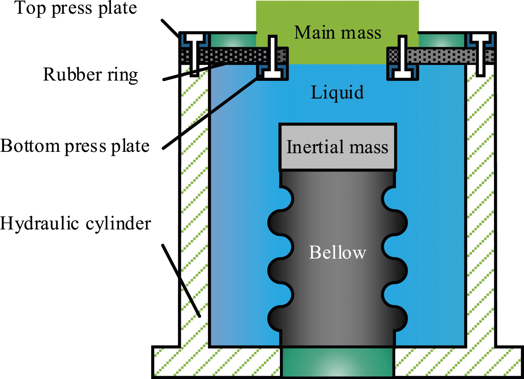
This paper aims to introduce the HLVI to suppress the longitudinal vibration of the shafting system caused by the axial force of the propeller. The paper is organized as follows: First, presents the dynamic model of the shafting system with the HLVI. Second, the numerical and experimental investigation of the proposed control scheme is shown, and the feasibility of the control strategy is discussed. Finally, the concluding remarks are given.
Dynamic model
Dynamic modeling of the isolator
Figure 2 shows the lumped parameter model of the HLVI, this is discussed in more detail in,
28
for simplicity, the viscous damping is neglected in the figure. M, mis represent the main mass and the inertial mass of the isolator, and k1, k2, k3 denote the main stiffness, volumetric stiffness and the bellow stiffness. x1, x2, x3, x4 are the displacements of the main mass, pivot point 2 of the inertial mass and foundation, respectively. Different from the model given in ref,
28
the elasticity of the foundation is taken into consideration. Lumped parameter model of the HLVI.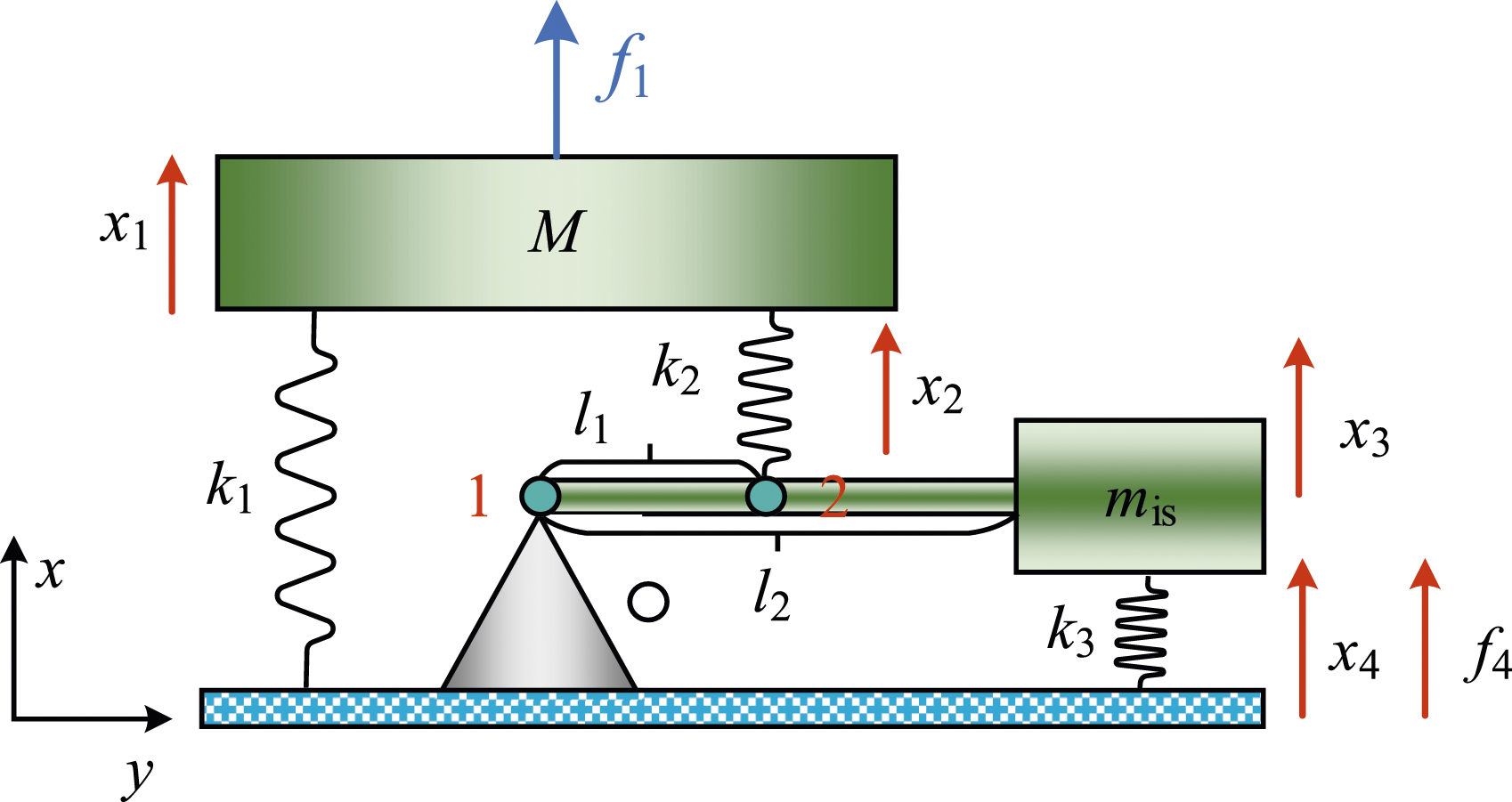
For the main mass M its dynamic equation can be given as

For the lever, according to the force and moment balance acting on it

Assuming the lever is rigid, massless, and the amplitude of vibration is small then the following relationship can be obtained

Substituting this relationship into equation (2), then the f4 can be obtained as

By assuming the displacements and the forces acting on the isolator are x
i
= X
i
eiωt, f
i
= F
i
eiωt (i = 1, 2, 3), X
i
and F
i
are amplitude of displacement response and excitation force, ω is the corresponding circular frequency. Then F4 and the dynamic stiffness of the isolator can be obtained as


Finally, the force transmissibility of the isolator can be written as

According to equation (5) the relationship between the inertial mass and the isolation frequency can be written as

Modeling of the shafting system with the isolator
As mentioned, a hydraulic leveraged anti-resonance vibration isolator is proposed to control the axial vibration of the propeller-shafting system, which is shown in Figure 3. As shown in the figure, the shaft comprises a tail shaft and main shaft. Due to only the low frequency vibration being considered, the tail shaft can be treated as a lumped mass and denoted by m, it connects to the bed frame and the main shaft with two springs, which are represented by k
a
and k
t
, respectively. Point 1, 2, 3 represents the ground point, the excitation point of the tail shaft, the junction point between the tail shaft and the main shaft. The main shaft is treated as a uniform rod with length ls, cross-sectional area As, Young’s modulus Es, and density ρs, where lse represents the distance between point 3 and the thrust bearing. Because only the axial vibration is considered in this paper, only the thrust bearing is given, which is simplified as a mass-spring system, and its mass and stiffness are, respectively, denoted by mb and kb. The HLVI is shown as a lumped parameter model, which is described in the dynamic modeling of the isolator part. The foundation and the bed frame are treated as an impedance boundary condition. f
t
, f
h
and f
f
are the axial fluctuating forces on the tail shaft, the isolator and the foundation, respectively, and the corresponding displacements are denoted as x
t
, x
h
and x
f
, which are not shown in the figure for the sake of clarity. Schematic diagram of the scaled shaft-foundation system.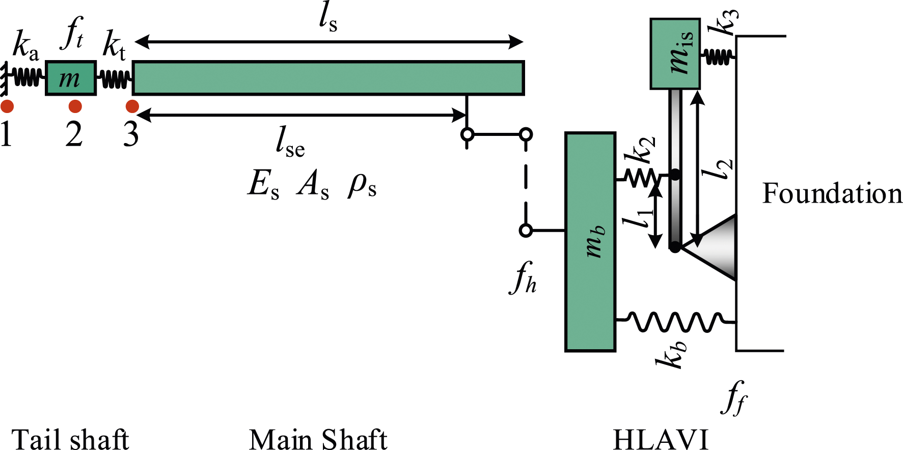
Using the four-pole parameter method, the force and velocity relationship between point 1 and point 3, then the origin mobility of point 3 can be obtained as

Assuming

The governing longitudinal vibration equation of the main shaft can be written as
29

To solve the homogeneous problem, the separation of variables of equation (11) is assumed
18

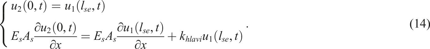
For the left boundary condition using the displacement continuity condition at point 3

For the discontinuity point, considering the compatibility conditions at the interface point for the displacement and force, the following formula can be deduced
Substituting equation (12) into equation (14) yields


The right boundary condition can be given as

Substituting equation (12) into equation (17) it becomes

Combining equations (13) and (18), the integral constants for the first part of the main shaft can be expressed as

Then the integral constants of the second part of the main shaft can be determined by using equation (15). Thus, the frequency response function of the main shaft can be written as

Numerical and experimental investigation
Parametric study
A parametric study is carried out to investigate the influence of the k1, k2, k3 and α on the force transmissibility of the shafting system under axial force excitation. Based on the force transmissibility equation shown in equation (7), the following expressions are introduced to normalize the equation

Then the equation (7) can be rewritten as
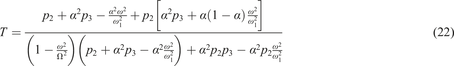
Firstly, the influence of k1 on the force transmissibility is investigated, with the range of variation of k1 set as [1 × 10⁵, 1 × 10⁶] with a step of 1 × 10⁴. Additionally, α = 3, p2 = 1, p3 = 0.1, mis = 0.6 kg, M = 10. It should be noted that the specific values of these parameters do not affect the results of the parameter analysis. This point will not be reiterated later in the text. The force transmissibility of the isolator is shown in Figure 4. It can be observed that the two resonant peaks and the anti-resonant peak dependent on k1. The frequencies corresponding to these three peaks will increase with an increase in k1. The isolation bandwidth will also increase with the increase of k1. Therefore, to obtain better isolation performance, k1 should be as large as possible. However, according to the configuration of the control scheme given in this paper, k1 represents the stiffness of the oil film of the thrust bearing, so this value can be considered as given. Comparison of force transmissibility for different k1.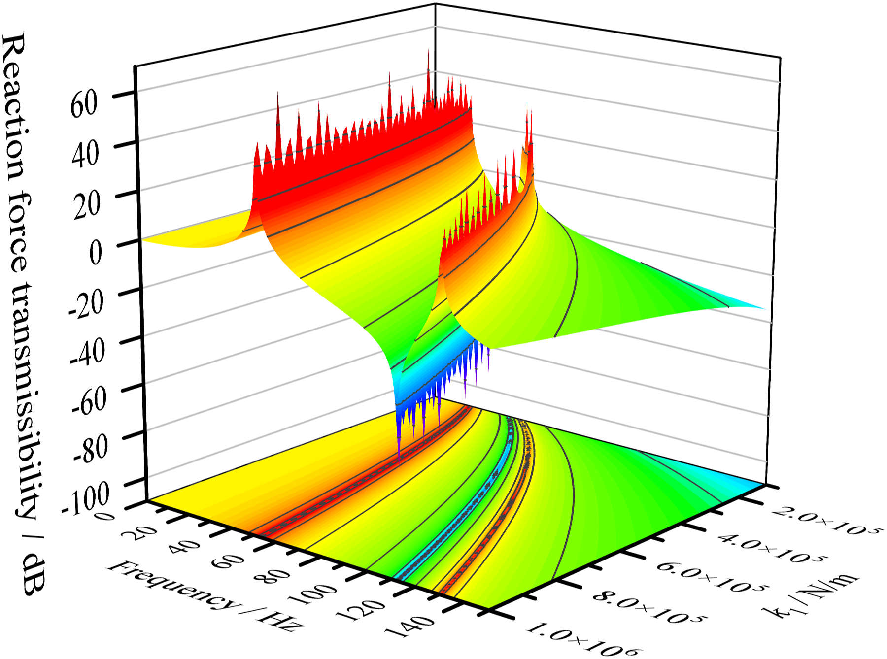
Secondly, a parametric study is conducted on p2, which is set as [0.1, 1] with a step of 0.02, k1 = 9 × 10⁵ N/m. The values of α, p3, mis and M remain the same as before. The force transmissibility of the isolator is shown in Figure 5. It can be seen that the first resonant peak is basically independent on p2. This indicates that the first mode of the isolator is independent of k2. Meanwhile, the second resonant peak and the anti-resonant peak gradually increase with an increase in p2. When p2 is smaller than 0.2, the anti-resonant peak disappears. Therefore, selecting a larger p2 is reasonable to achieve better isolation performance. Comparison of force transmissibility for different p2.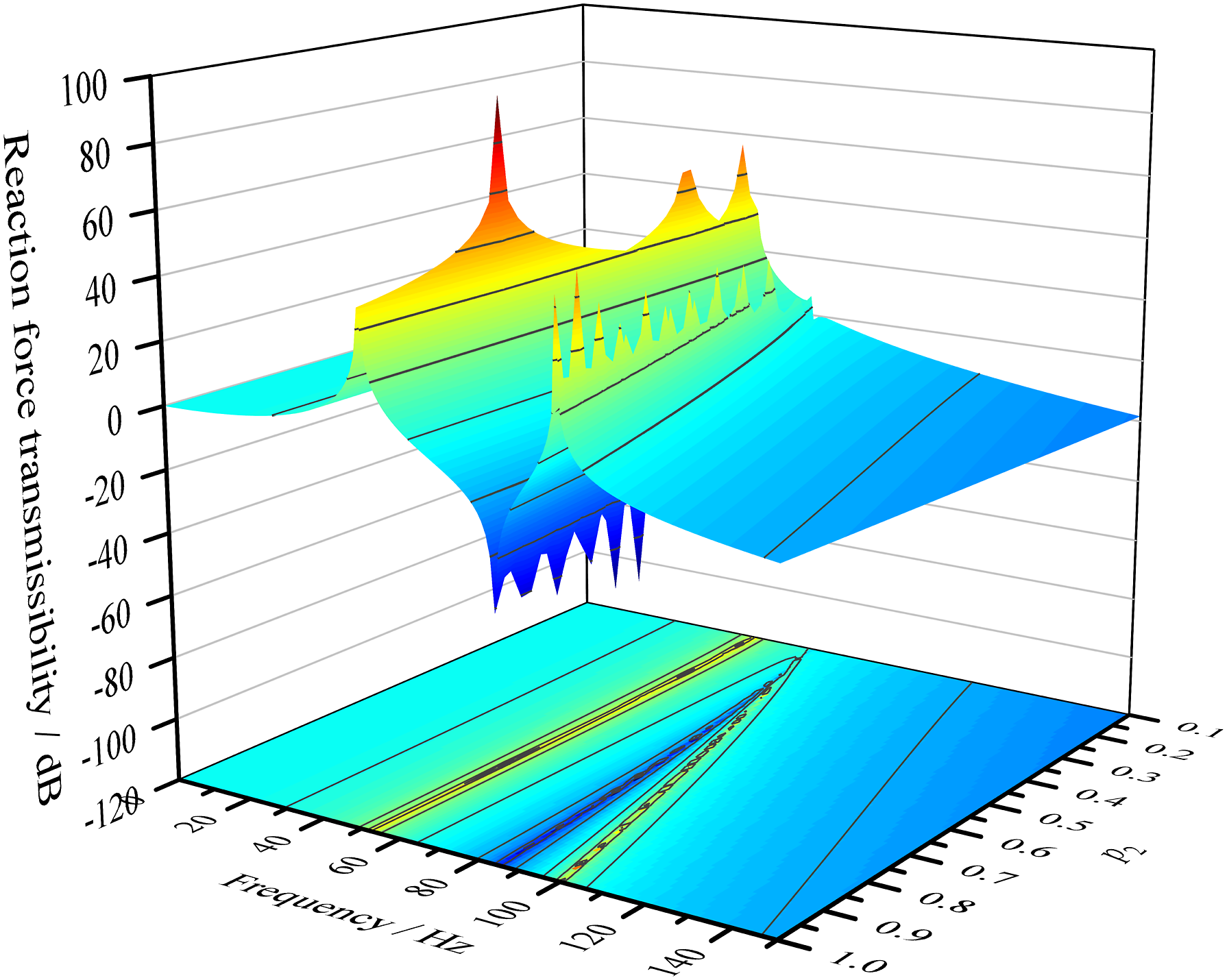
Then the influence of p3 on the force transmissibility of the isolator is investigated, and its value is set as [0.1, 1] with a step of 0.1. The other parameters are given as follows: α = 3, k1 = 9 × 10⁵ N/m, p2 = 1, mis = 0.6 kg, M = 10 kg. The force transmissibility of the isolator is presented in Figure 6. It is observed from Figure 6 that as p3 increases, the first resonant peak increases and then basically remains unchanged. Comparison of force transmissibility for different p3.
However, p3 has a great influence on the other resonant peak and the anti-resonant peak. When p3 is about 0.3, the anti-resonant peak and the second resonant peak coincide with each other, indicating that the isolator has no isolation effect. Therefore, in reality, it is better to select a smaller p3 to achieve a low frequency isolation effect.
Finally, the influence of the lever ratio α on the force transmissibility is studied. Figure 7 illustrates that the first resonant peak is basically independent of α. While the second resonant peak and the anti-resonant peak decrease with the increase of α, when the α reaches a certain value, these two peaks basically remain unchanged. This indicates that the larger the lever ratio, the smaller the isolation bandwidth will be. Therefore, it is desirable to select a relatively small lever ratio to achieve better isolation performance. Comparison of force transmissibility for different α.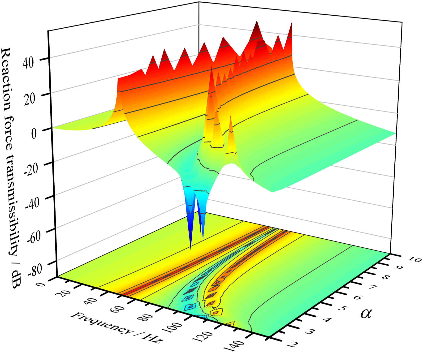
Force transmissibility
First, the longitudinal vibration properties of the scaled shaft must be clarified. The scaled shafting system in this paper consists mainly of three parts: (1) the scaled shaft with its foundation; (2) the excitation part; and (3) the common infrastructure.
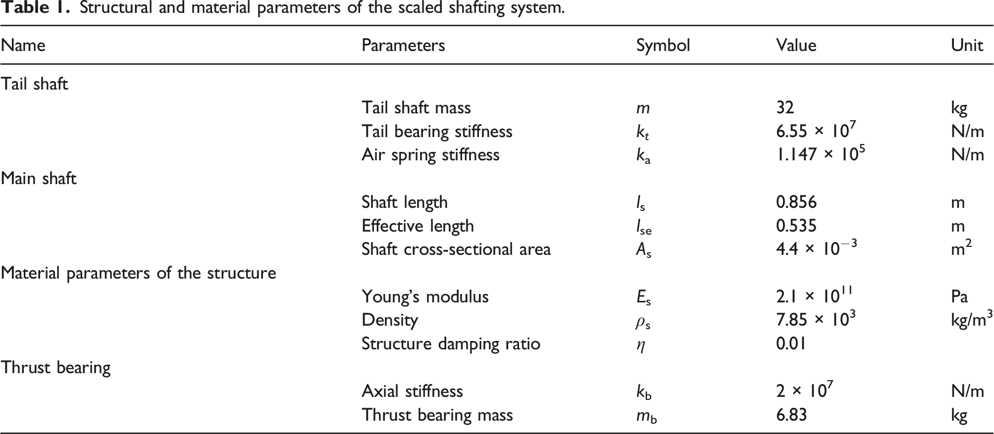
Structural and material parameters of the scaled shafting system.
The elasticity of the foundation is considered by using the FEA in this paper. Substituting the elastic characteristic into equations (4) and (7), the longitudinal force transmissibility of the shaft can be obtained as shown in Figure 4. There are two resonance frequencies within the considered frequency range, which are approximately 65 Hz and 86 Hz. The main motion of the first mode is that of the foundation in phase with the motion of the shaft. The second mode is an antiphase motion between the shaft and the foundation. According to the working principle of the isolator, the second mode is selected as the isolation frequency. As shown in Figure 3, the isolator is installed in parallel with the thrust bearing. To avoid affecting the equivalent stiffness of the thrust bearing, the stiffness of the isolator is assumed to be much smaller than the stiffness of the thrust bearing. The main stiffness of the isolator can be assumed as 1 × 10⁶ N/m. Based on the parametric study illustrated in Figure 5, it can be concluded that a larger p2 can achieve a better isolation performance. Therefore, p2 is set to 0.8, corresponding to k2 = 8 × 10⁵ N/m. Similarly, based on the results in Figures 6 and 7, p3 and α are assumed to be 0.05 and 3, respectively, corresponding to k3 = 5 × 10⁴ N/m. Based on the parameters given above, the inertial mass of the isolator can be obtained as approximately 0.5 kg using equation (8).
In order to comparison, the isolation performance of the Resonance Changer (RC), which has been widely studied for suppressing the longitudinal vibration of the shafting system, the configuration of the RC in the shafting system is kept the same as that in the reference. According to the parameters of the shaft and the isolation frequency, the parameters of the RC are kr = 2 × 10⁷ N/m, mr = 68.5 kg. Then, the reaction force transmissibility of the scaled shafting system with the HLVI and RC can be calculated, as shown in Figure 8. The figure indicates that both isolators can effectively suppress axial vibration at the target frequency. However, the control scheme with the RC greatly reduces the first natural frequency of the shaft, which may reduce the propulsion efficiency of the shafting system. In contrast, the control scheme with HLVI doesn’t have that problem, as the frequency and amplitude of the first peak are slightly decreased. The reason for this is that after the HLVA is installed, the effective mass of the system is increased. The additional inertial mass needed for the HLVA, which is about 0.6 kg, is much smaller than that of the RC, which is about 68.5 kg. Therefore, generally, the control scheme proposed in this paper is superior to the control scheme with RC. Reaction force transmissibility from tail shaft to the foundation by the semi-analytical model.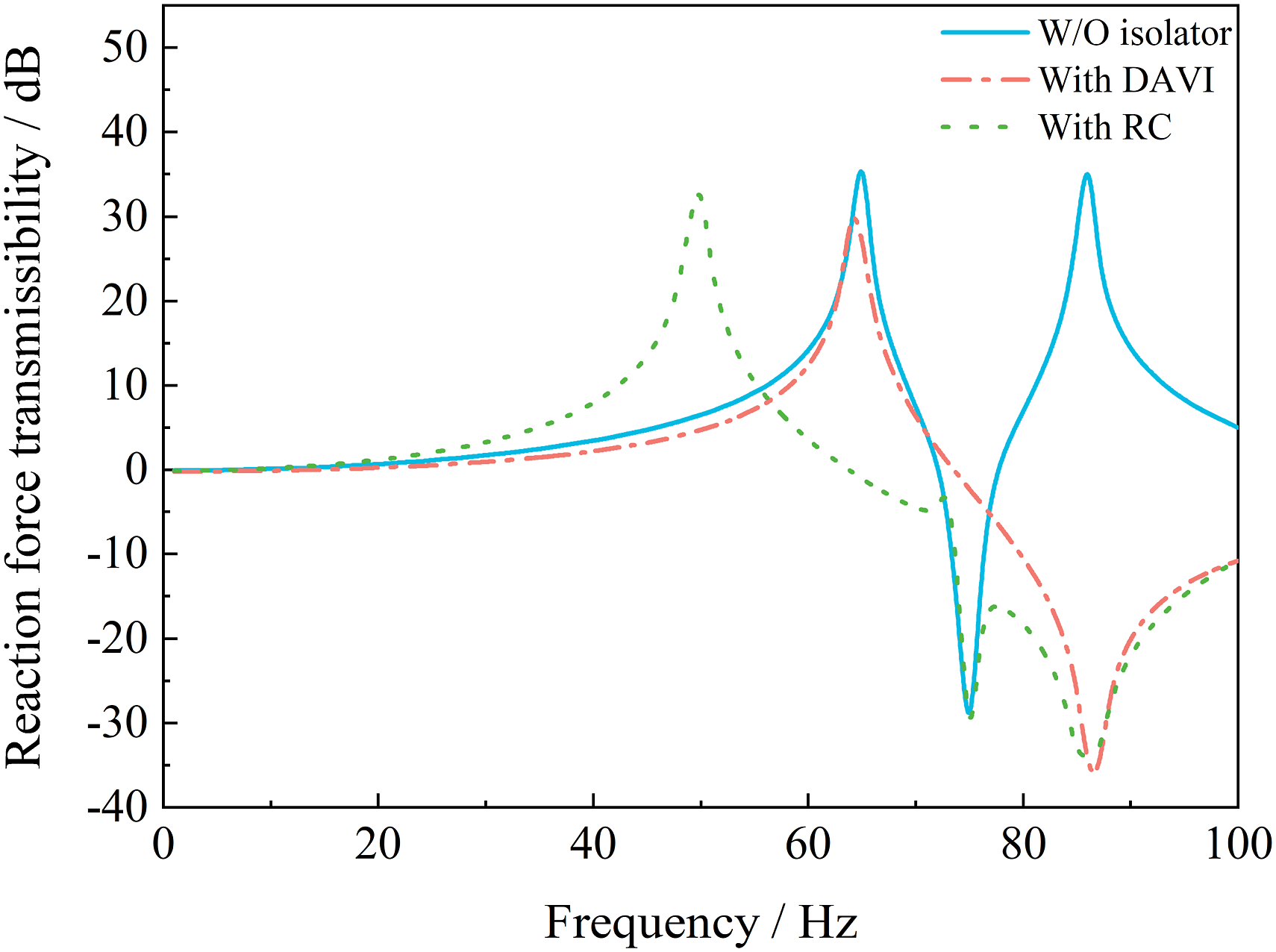
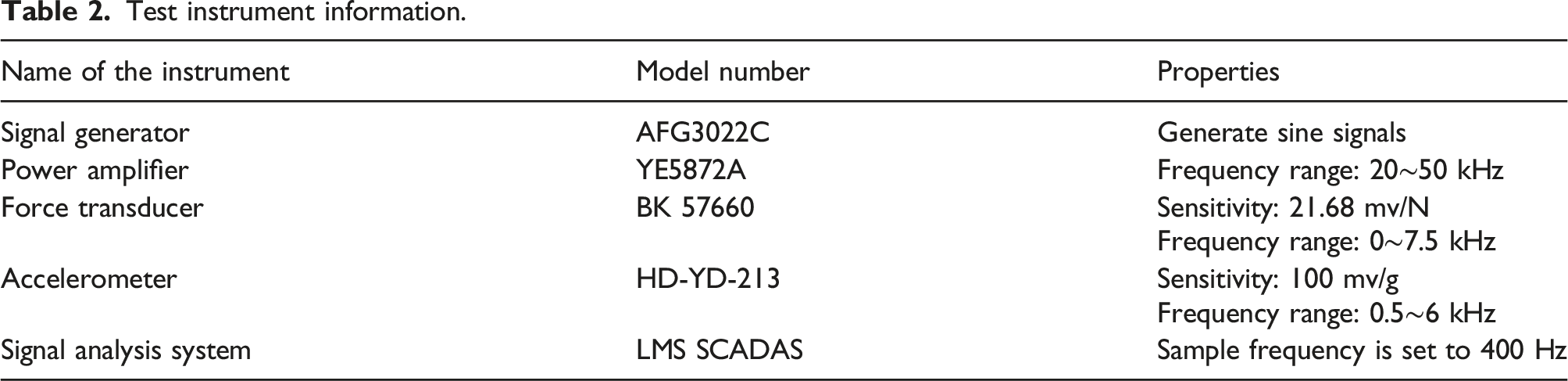
In order to validate the results given in the Figure 8, an experimental apparatus has been setup as shown in Figure 9. The parameters of the setup are listed in Table 1. The spectral testing method was used to determine the longitudinal vibration characteristics of the scaled shafting system. A force transducer is arranged between the tail shaft and the exciter. Nine three-direction accelerometers are pasted on the scaled shaft, and they are used to obtain the x direction acceleration response of the shaft under axial excitation. The no. 1 and no. 8 accelerometers are used to measure the axial acceleration response of the shaft. The no. 9 accelerometer is used to test the axial acceleration of the tail shaft. The foundation’s axial acceleration is measured using accelerometers ranging from no. 2 to no. 7. LMS SCADAS is used to obtain and postprocess the corresponding dynamic signal, and the force signal is used as the reference signal. The detailed information for the main instruments is tabulated in Table 2. The signal generator provides the desired axial sine excitation in the frequency range of 5–100 Hz. Then the acceleration frequency responses are shown in Figure 10. Using the modal synthesis method embedded in the LMS the longitudinal modal of the shaft can be identified as 76.1 Hz and 81.1 Hz. Then 81.1 Hz is selected as the isolation frequency. Schematic diagram of longitudinal vibration testing by using the spectral testing method. Test instrument information. Acceleration frequency response of the scaled shafting system.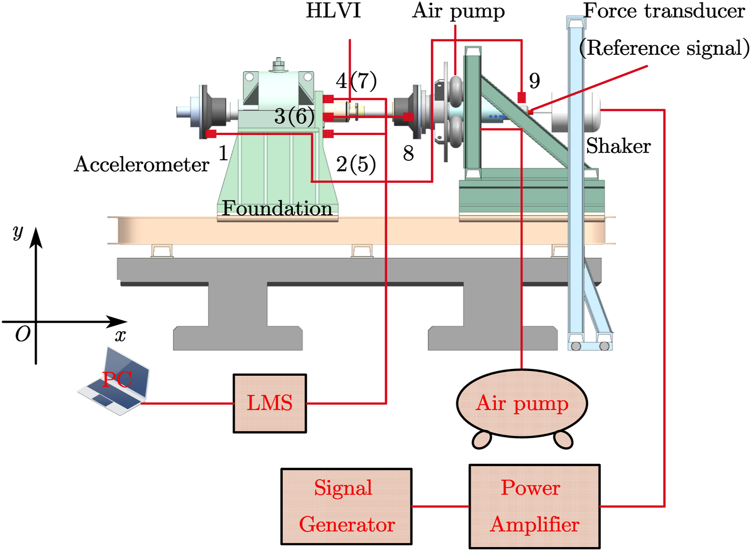
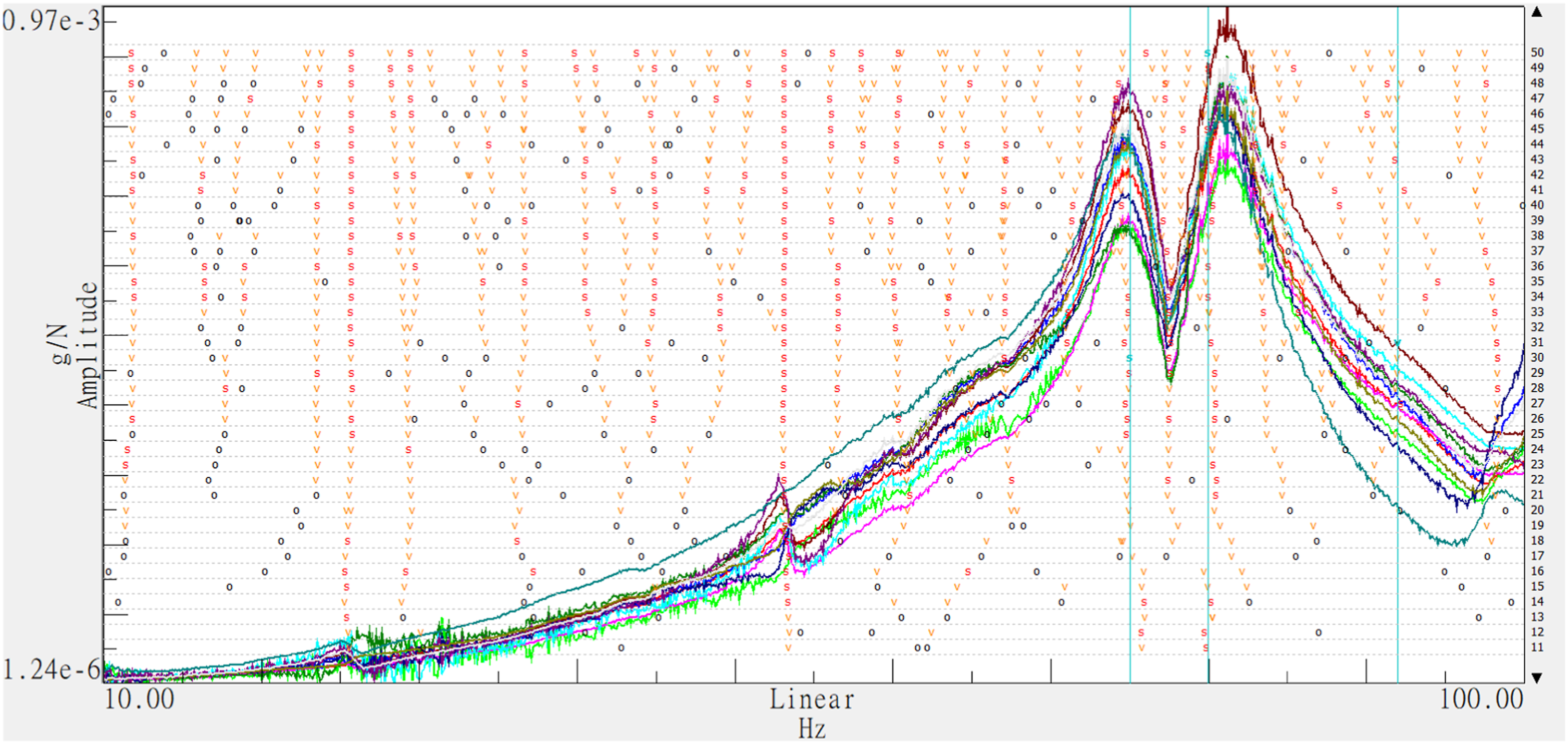
Compared to the theoretical results given in Figure 8. The relative errors for the natural frequencies are 17% and 6%, respectively: that is, the first natural frequency has a relatively larger error. According to the motion of vibration, this may be because there is no connection between the base and the ground, making the elasticity of the foundation difficult to simulate.
Experimental study
Dynamic characteristics of the isolators
The physical parameters of the rubber ring and bellow.
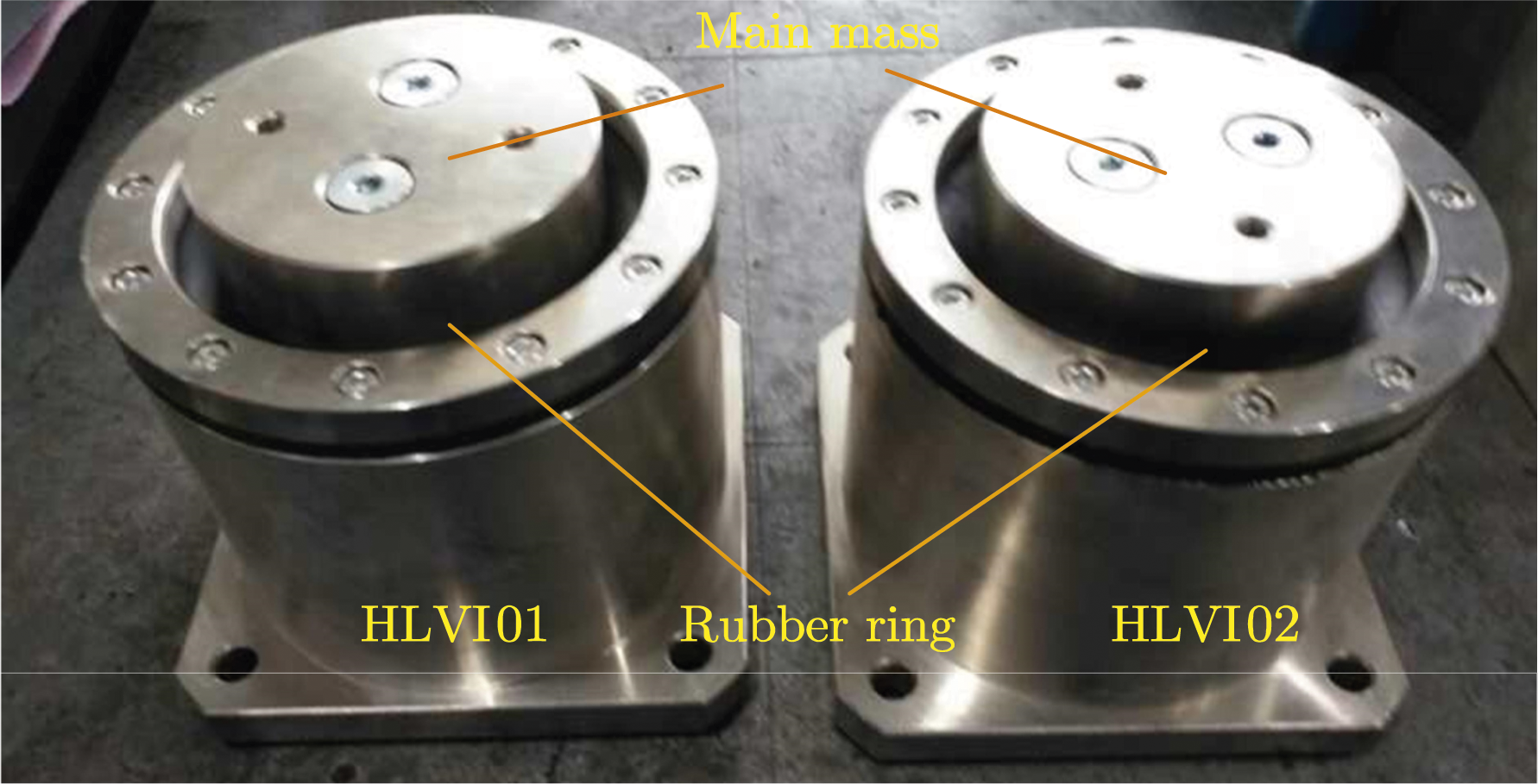
Prototype of the HLVI.
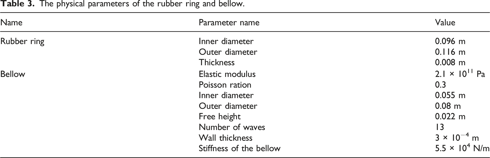
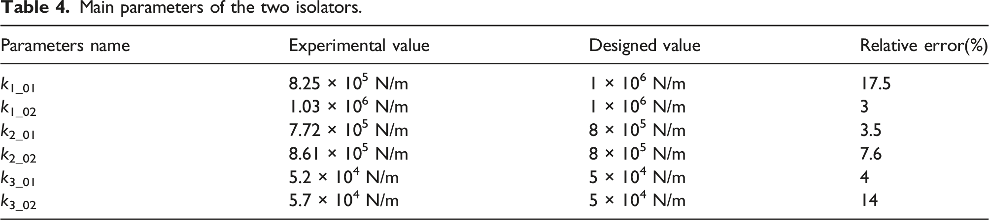
The dynamic characteristics of the two isolators are tested first. The results are shown in Figure 12. An electromagnetic vibration shaker (V8-640 LDS, England) was used to obtain the acceleration transmissibility shown in Figures 12(a) and (b) when the isolators were not filled with fluid. According to their natural frequency and the main mass of the isolators, their dynamic stiffness can be obtained. The stiffness of the bellows was tested by the MTS system (MTS system corporation, 14,000 Technology Dr, Eden Prairie, USA), and using its data acquisition system, the relationship between the force and the displacement was obtained as shown in Figures 12(c) and (d). Figures 12(e) and (f) depict the volumetric stiffness of the two isolators when filled with water. The main parameters of the isolators are summarized in Table 4. The first subscript of the letter has the same meaning as shown in Figure 3, whereas the second subscript represents the isolator’s number. It can also be observed from the table that due to the manufacturing error, the maximum relative error of the dynamic stiffness of HLVI01 reaches 17.6%, while the other relative error is within 10%. However, according to the isolation scheme, the dynamic stiffness of the isolator is mainly dependent on the thrust bearing, so the relative error of the dynamic stiffness has little effect on the isolation frequency. Therefore, the designed isolators can be used with confidence. Experimental value of the two isolators. Main parameters of the two isolators.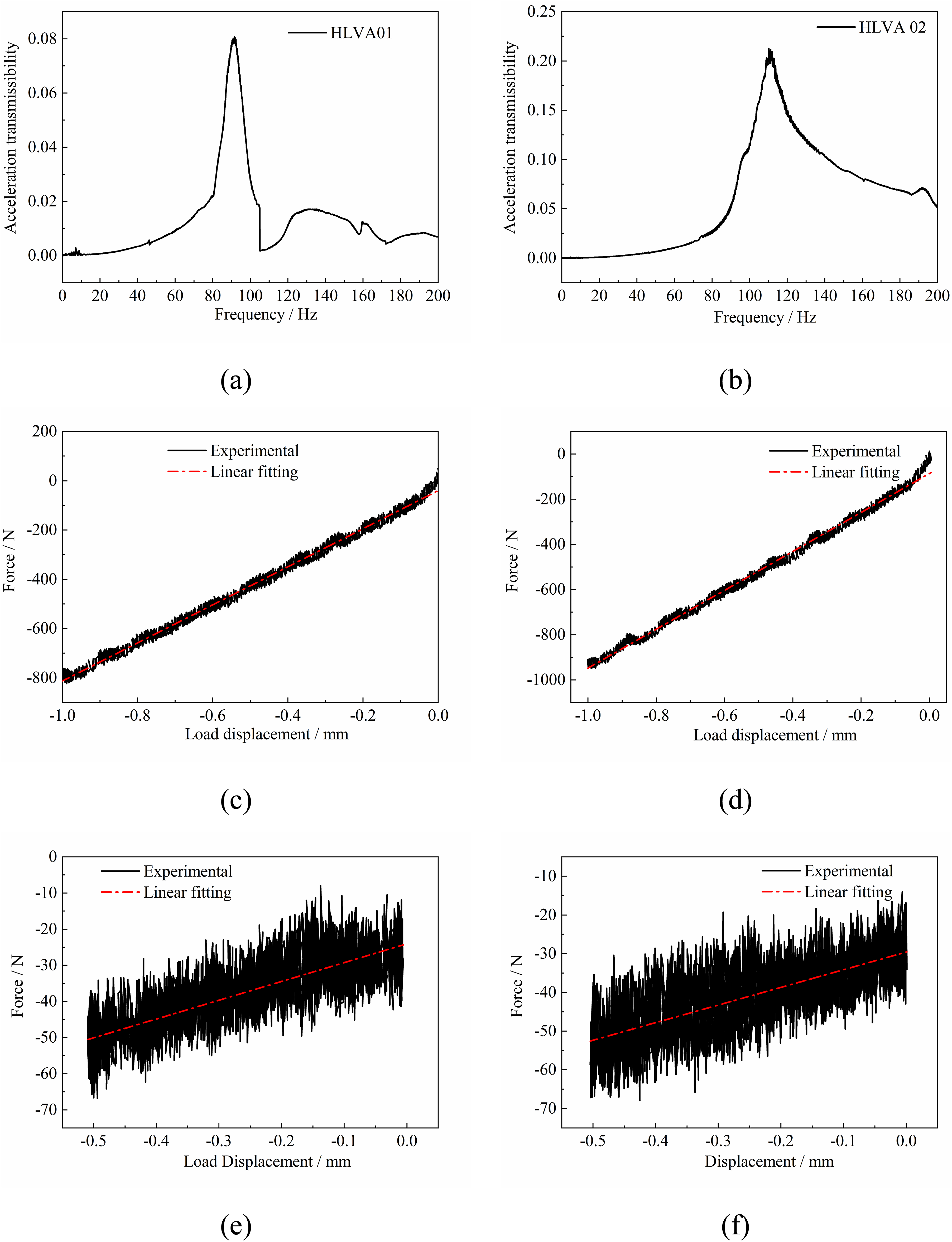
Isolation performance of the HLVI
The acceleration frequency responses of the foundation are used as the criterion to validate the isolation performance of the HLVI with respect to the scaled shafting system. As mentioned, two HLVIs are placed symmetrically on the two sides of the scaled shafting system, as shown in Figure 13. At the same time, two accelerometers are added to obtain the acceleration response of the inertial masses when the shaft is under axial excitation: they are numbered 10 and 11 as presented in Figure 13. The other accelerometers and apparatuses given in Figure 9 are not shown in this figure for the sake of brevity. The layout of the isolators.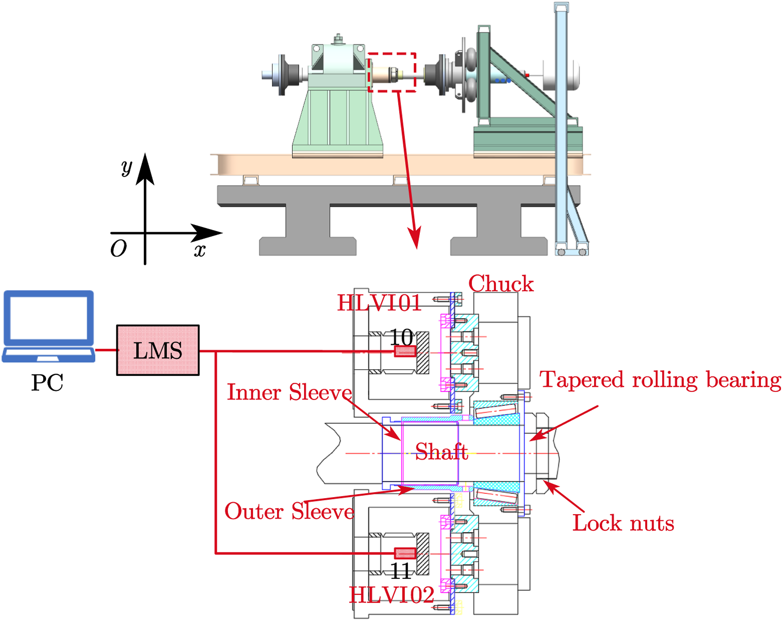
The righthand regions of the HLVIs are connected to the shaft through a chuck and a taper roller bearing, and the lefthand regions of the isolators are mounted on the foundation of the shafting system through bolts. The position of the chuck on the shaft can be adjusted by the lock nut and the sleeve. In the low frequency range, because the wavelength of the vibration is much larger than the size of the shafting system, the HLVI is oriented in parallel with the oil stiffness of the foundation. Therefore, the schematic diagram given in Figure 13 is equivalent to the control scheme given in Figure 3. The corresponding photographs of the experimental system are shown in Figure 14. Experiment setup for evaluating vibration isolation of the HLVI to the scaled shafting system.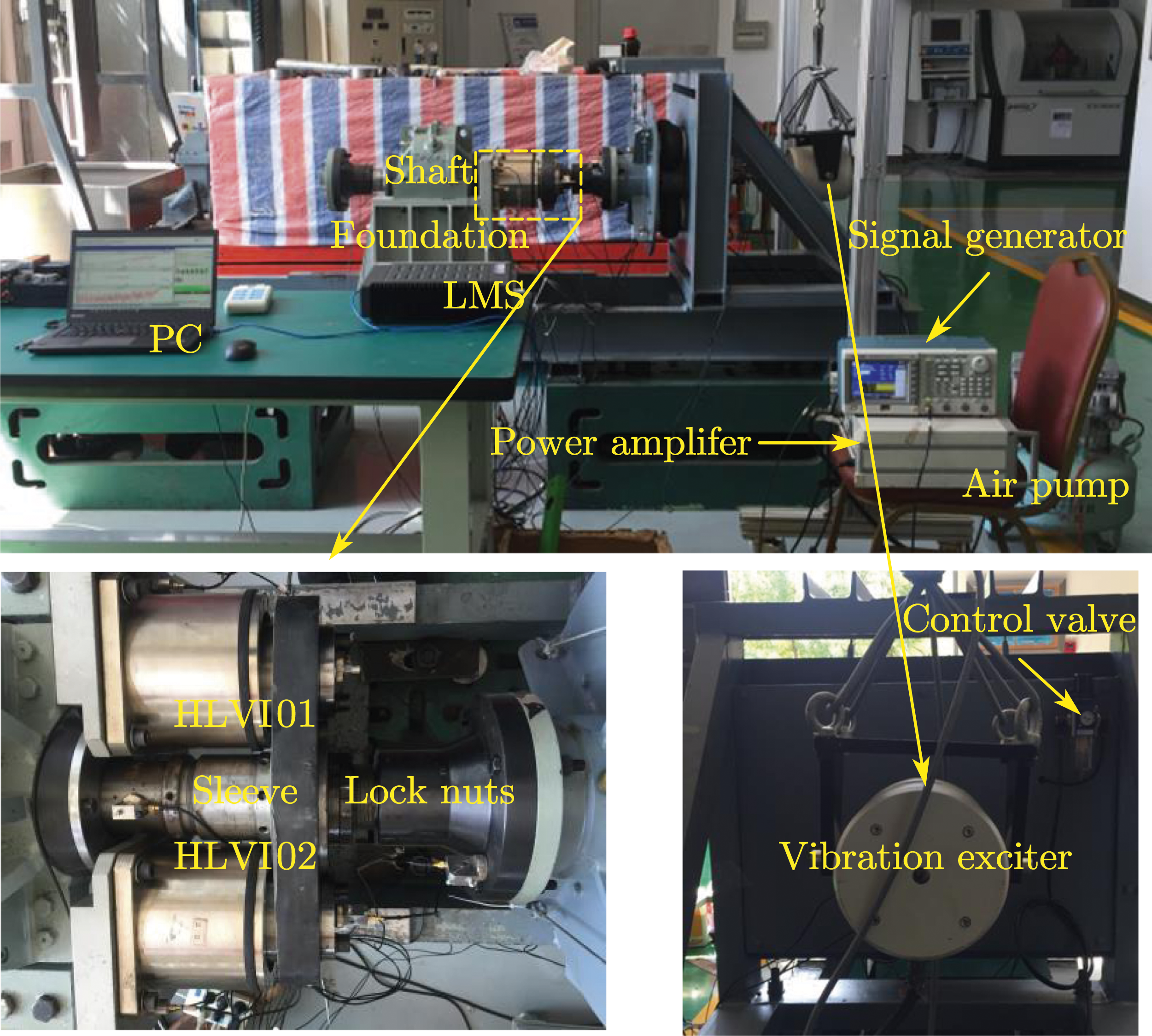
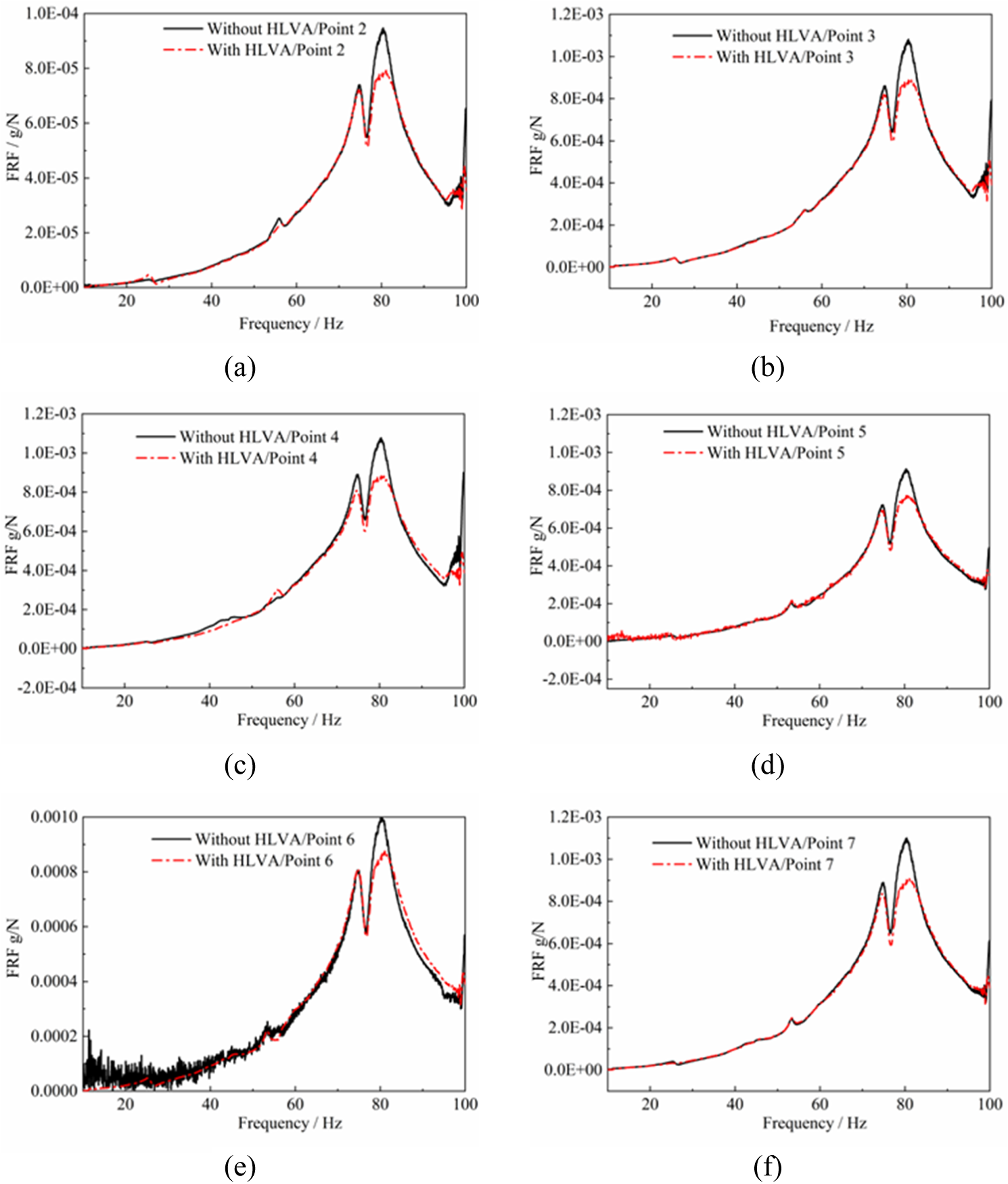
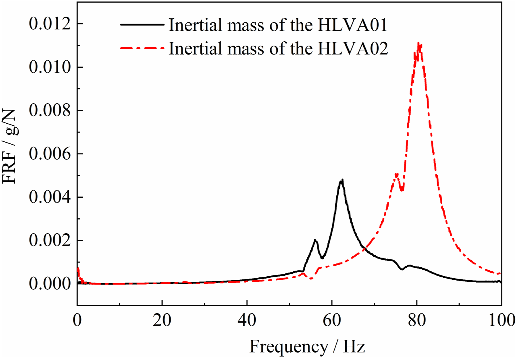
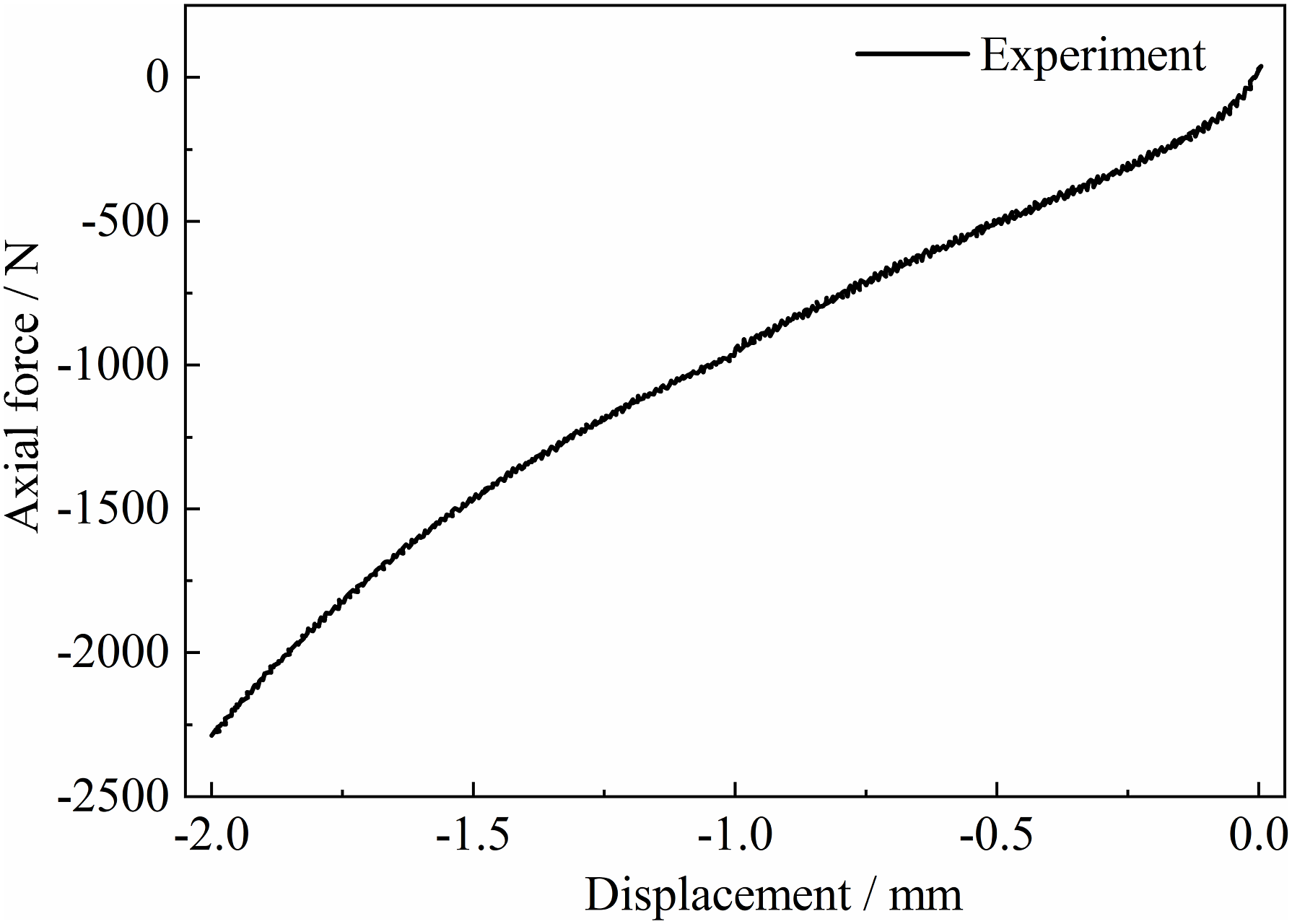
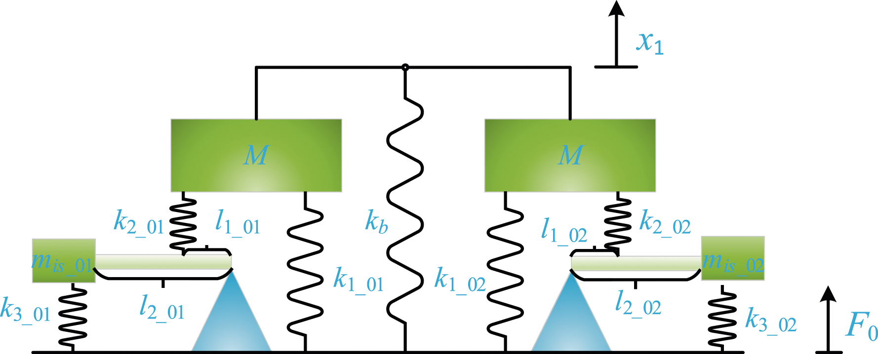
According to the input driving signal, the electromagnetic shaker provides the desired axial excitation in the frequency range of 10–100 Hz, and the excitation amplitude can be adjusted by the driving signal voltage. A sinusoidal sweeping signal is used. The acceleration frequency responses of the foundation when the HLVI is filled with and without water can be measured as shown in Figure 15. This indicates that when the HLVIs are filled with water, the amplitude of the acceleration frequency response of the foundation is decreased by approximately 1.75 dB at the designed frequency. This value is much smaller than the theoretical attenuation quantity given in Figure 8. To explore the reasons for this, the acceleration frequency responses of the inertial masses are measured, and the results are presented in Figure 16, indicating that the amplitude of the inertial mass of the acceleration frequency response of HLVI01 is at (80.5, 0.011), and that of the other one is at (62.1, 0.005). This means that at the designed isolation frequency, the amplitude of the acceleration response of the inertial mass of HLVI01 is magnified, while that of HLVI02 is not. Therefore, HLVI01 works as desired, while HLVI02 does not. This will significantly reduce the isolator’s vibration isolation capability. However, in Figure 15 at the isolation frequency, the obvious anti-resonance point is not observed. This is mainly due to the damping of the system. The reason why the two isolators do not function simultaneously is that their precompressions are different. By comparing the heights of the two isolators, it can be found that HLVI02 is 0.4 mm taller than HLVI01. This leads to the fact that after preloading, the compression amount of HLVI02 is approximately 1.4 mm and that of HLVI01 is approximately 1 mm. As a result, the two isolators are in different mechanical states. The volumetric stiffness of HLVI02 was then tested, and the result is depicted in Figure 17, indicating that the volumetric stiffness of HLVI02 is nonlinear. The volumetric stiffness can be calculated using the slope at 1.4 mm, which is approximately 1.3 × 10⁶ N/m. The other parameters of the isolators are the same as given in Table 4. Because the parameters of the two isolators are totally different, the dynamics of the thrust bearing need to be reformulated. The new model of the thrust bearing is shown in Figure 18. The amplitude of the force transmitted to the foundation F0 can be deduced using the same procedure given in 2.2 Vibration responses of the scaled shafting system: (a)–(f) depict acceleration frequency responses measured at points 2–7. Acceleration frequency responses of the inertial mass measured at point 10 and point 11. Axial force versus displacement of the HLVI02. Lumped model of the thrust bearing of the experimental test rig.
Using equation (23) and substituting the parameters into it, the isolation frequencies can be obtained as 61.4 Hz and 79.2 Hz, quite near 62.1 Hz and 80.5 Hz. The results also show that if the parameters of the two isolators differ, the isolation frequency will be inconsistent.
The acceleration responses above were obtained by the sweeping method. The excitation time was relatively short, and steady responses of the vibration may not have been achieved. The discrete sinusoidal excitation test was conducted with the excitation frequency range set to 70–85 Hz, close to the isolation frequency, with a step length of 0.2 Hz. The excitation time was set to 40 s for each discrete frequency. The amplitudes of the acceleration responses of the accelerometers were acquired when the responses achieved stability. The spectrum was calculated using FFT (Fast Fourier Transform), and the force signal was set as the reference. The sampling frequency used to perform FFT was 512 Hz. Because the acceleration response of each point on the foundation is basically the same, only the response of point 3 is presented in Figure 19. It is found that under this condition, the bandwidth of the isolation is approximately 7 Hz. The first resonance frequency of the system is basically the same as before. The maximum attenuation of approximately 1.75 dB of the acceleration frequency response occurs at approximately 80.4 Hz, which is consistent with the results obtained by the sweeping method. Experimental results of the acceleration frequency responses of the scaled shaft under longitudinal discrete sinusoidal excitation.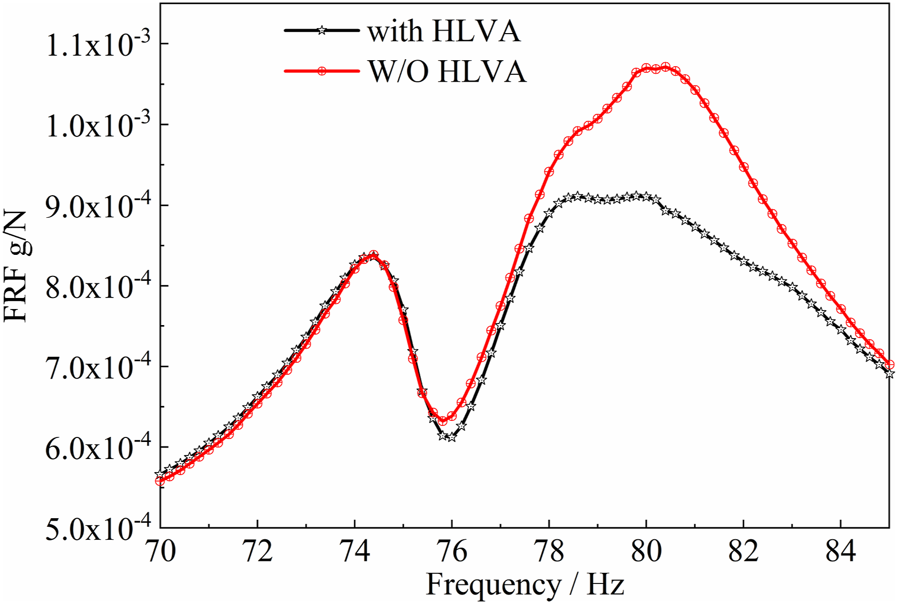
Generally, HLVI can suppress the longitudinal vibration of the shafting system induced by axial excitation with a mass ratio of approximately 1.5%.
Conclusion
A new longitudinal vibration control method using HLVI for the shafting system is proposed. The dynamic model of the scaled shafting system is formulated using the frequency response synthesis method. The effects of parameters on force transmissibility are investigated further in parametric studies. Experimentation with the shafting system with HLVI is conducted in this paper. The following remarks may be drawn from the analysis: (1) a parametric study finds that, to achieve a better isolation performance, the stiffness ratio p2 of the isolator should be designed to be larger, while the stiffness ratio p3 and lever ratio α should be designed to be smaller; (2) the working principle of the HLVI is similar to DVA with amplification abilities; at the isolation frequency, the energy of the isolated object is transferred to the inertial mass of the isolator; (3) the HLVI can effectively attenuate the axial vibration of the shafting system; in this paper, two HLVIs are used to isolate the vibration of the system, but only one functions, and the experimental results show that it can mitigate approximately 1.75 dB of the longitudinal vibration with a mass ratio of 1.5% and a 7 Hz bandwidth; (4) if multiple isolators are used, their parameters should be as consistent as possible; otherwise, the isolation frequency will be different; (5) the volumetric stiffness of the HLVI is nonlinear when the compression exceeds a certain value.
Footnotes
Declaration of conflicting interests
The author(s) declared no potential conflicts of interest with respect to the research, authorship, and/or publication of this article.
Funding
The author(s) disclosed receipt of the following financial support for the research, authorship, and/or publication of this article: This work is supported by National Natural Science Foundation of China (Grant No. 52105091, No. 12272094), State Key Discipline Laboratory of Noise and Vibration Control of Ship Equipment in Shanghai Jiaotong University under (Grant No. VSN202103), Fujian Provincial Natural Science Foundation (Grant No. 2021J05115), National Key Laboratory on Ship Vibration and Noise (Grant No. 6142204230403).