
Abstract
In this paper, an enhanced integral force feedback controller is proposed for implementing active damping. Compared with the classical integral force feedback, the pure integrator is replaced with a combination of a first-order low-pass filter and a proportional term. The control performance of the proposed controller is examined on a single-degree-of-freedom host system. In order to better understand the physics behind, a full equivalent mechanical model is derived. It is found that the first-order low-pass filter is mechanically equivalent to a spring and a damper connected in parallel. The proportional term mechanically represents a spring which is connected in series with the inherent actuator spring. The optimal control parameters are numerically obtained with the ℋ∞ optimisation criterion. The analysis shows that the optimal feedback gain can be practically taken the same as that of the classical integral force feedback controller in the sense that the difference between the resultant control performance is negligible. The numerical study is also experimentally validated. The obtained results are found to correspond well with the theoretical developments.
Introduction
From the standpoint of energy conservation as well as ultra-high performance, there is a prevailing inclination towards lightweight structures and integrated designs in contemporary technological and industrial developments.1,2 However, lightweight materials are more prone to vibrations, which may cause many issues including impairment of the precision instruments and equipment, decreased accuracy in mechanical processing, detrimental effect on comfort, and even structural fatigue damage. Therefore, vibration reduction techniques should be considered during the design phase. Typical solutions such as damping and isolation are often found. 3 Vibration isolation is to limit the propagation of disturbances to sensitive parts of the systems such that these key parts are less influenced.4,5 It is often used for the cases where excessive response of the sensitive systems to the external excitations is concerned, but yield limited control effectiveness for mitigating the structural resonance peaks of the sensitive systems themselves.
In such scenarios, vibration damping should be implemented. Damping can be achieved passively, with viscoelastic materials, viscous fluids or eddy-currents, or by transferring kinetic energy to tuned mass dampers (TMDs). 6 A TMD typically comprises a mass block, spring, and energy dissipation damping system as an auxiliary device. 7 The damping effectiveness is known to ultimately depend on the weight of its proof mass, where better control performance comes with a heavier proof mass. However, the added mass may be penalising in lightweight applications. Piezoelectrical material thus becomes more attractive for implementing vibration damping. The mechanism is to bond piezoelectrical material, which is shunted with electrical networks, to the structures. When they deform, vibration energy is transformed into electrical energy and dissipated in electrical networks, or stored (energy harvesting). Piezoelectric transducers are also found to be equipped with switched electrical networks, which can be then featured as semi-passive dampers.8,9
When high performance is needed, active damping can be used, which involves a set of sensors (strain, acceleration, velocity, and force), a set of actuators (force, inertial, and strain), and a control algorithm (feedback or feedforward). By active damping, the primary objective is to relocate the negative real parts of the closed-loop system poles such that the peak response of the system is suppressed. This strategy often requires relatively little control effort since only the control loop gain around the resonance frequency needs to be considered. Active damping can be implemented, for example, by directly feeding back velocity signals, or passing displacement signals through a second-order filter, or integrating acceleration signals, to drive control actuators.10–13 However, in practice, flexibilities between actuators and sensors may introduce unwanted phase delays, which would limit the achieved damping performance. 14
Integral force feedback (IFF) may exhibit advantages in this regard as collocated control plants (zeros and poles are interlacing) are more easily achieved with IFF control. 3 By collocation, it means that each phase lag induced by the poles will be compensated by the phase lead of the same amount introduced by the adjacent zeros. One important design concern with an IFF control system is how to calculate the optimal feedback gain. Two kinds of optimisation criterion, the maximum damping criterion and the ℋ∞ optimisation criterion, were adopted for designing an IFF controller.15,16 The optimal feedback gain obtained with the maximum damping criterion is sought to obtain the most achievable damping for one specified structural mode, while that with the ℋ∞ optimisation criterion is set to minimise the maximum steady state response of the structure. In order to further improve the control performance, several modified IFF controllers were proposed, where the single integrator is superimposed with a second-order integrator or fully replaced by a resonator.17–19 However, more control parameters need to be configured which may jeopardise the robustness of the control system.
The focus of this study is thus to develop a modified force feedback controller which allows to further boost the control performance, but with less control parameters to be optimised. The proposed controller is built upon our previous developments.16,18 A proportional term is added to the original controller which allows to adjust the effective stiffness of the actuator as in.20,21 On top of this, a simple first-order low-pass filter is used to replace the pure integrator in the original controller which helps limit the saturation problems for example caused by the low-frequency drift of the instrument in practical applications. The ℋ∞ optimisation criterion is utilised to examine the influence of the cut-off frequency of the first-order low-pass filter on the control performance. The mechanical equivalence of the components in the proposed controller is also derived in order to better understand the physics behind. Experimental validations are provided which verify the theoretical analysis. The principle contributions are as follows: (a) the development of the equivalent mechanical models which enables a straightforward interpretation of the physics behind the proposed controller, (b) the investigation of the influence of the cut-off frequency of the first-order low-pass filter on the control performance, and (c) the experimental validation of the theoretical analysis.
The paper is structured into four sections. In the second section, the mathematical models are presented, based on which the optimal feedback gains for implementing the controller are derived. In the third section, experimental results are presented for the validation of the numerical study. The conclusions are drawn in the last section.
Mathematical modelling and parameter optimisation
Mathematical modelling
The system under investigation is shown in Figure 1(a). It represents an undamped single-degree-of-freedom (SDOF) system which is equipped with a massless actuator whose stiffness is denoted by (a) The schematics of the system under investigation and (b) the equivalent mechanical model.
The governing equations of the coupled system can be written as:


The proposed controller

Transforming equation (3) into Laplace domain, one obtains:

In order to better understand the physics behind the proposed controller, the pure mechanical presentation of the coupled system, that is, the mechanical system coupled with the electrical system is derived, which is shown in Figure 1(b). The proof is provided in Appendix A.
As can be also seen in Figure 1(b), the use of the first-order low-pass filter introduces a spring

When the gain
The corresponding equivalent damping coefficient

Note that the corner frequency related parameters
Compared with the classical integral force feedback controller as proposed in, 15 the pure integrator is now replaced by a first-order low-pass filter. In this way, the saturation problems due to the undesirable amplification of the control signal at low frequencies can be limited. The proportional term is introduced mainly to be able to tune the effective stiffness of the actuator as better control performance comes with a larger actuator stiffness.
Although the saturation problems can be suppressed by the proposed controller, the optical control gain g
s
needs to be revisited in the present of the corner frequency of the low-pass filter. Before proceeding with the optimisation, a more general formulation is implemented with the following parameters:
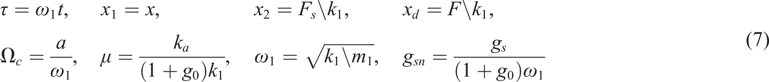
The system governing equations (1) and (2) are thus normalised:


Parameters optimisation
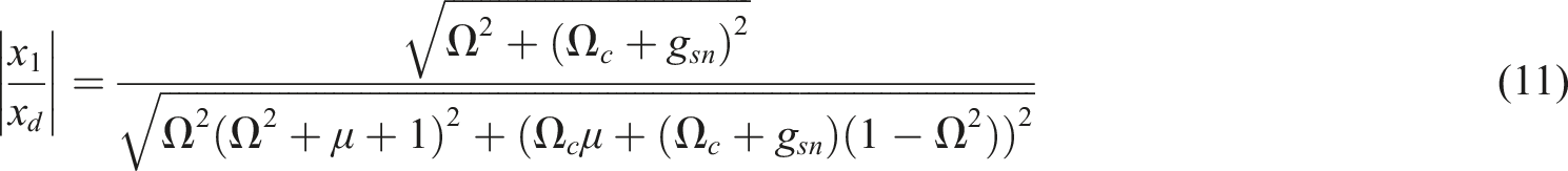
The ℋ∞ norm is employed to optimise the control parameters of the proposed controller. The magnitude of the normalised driving-point receptance
The normalised driving-point receptance of the primary structure can be derived according to equations (8) and (9):

The optimisation parameters could in principle be any of the three, that is,


The optimal gain The performance index against normalised frequency for different cut-off frequencies (left) and feedback gains (right) where the stiffness ratio 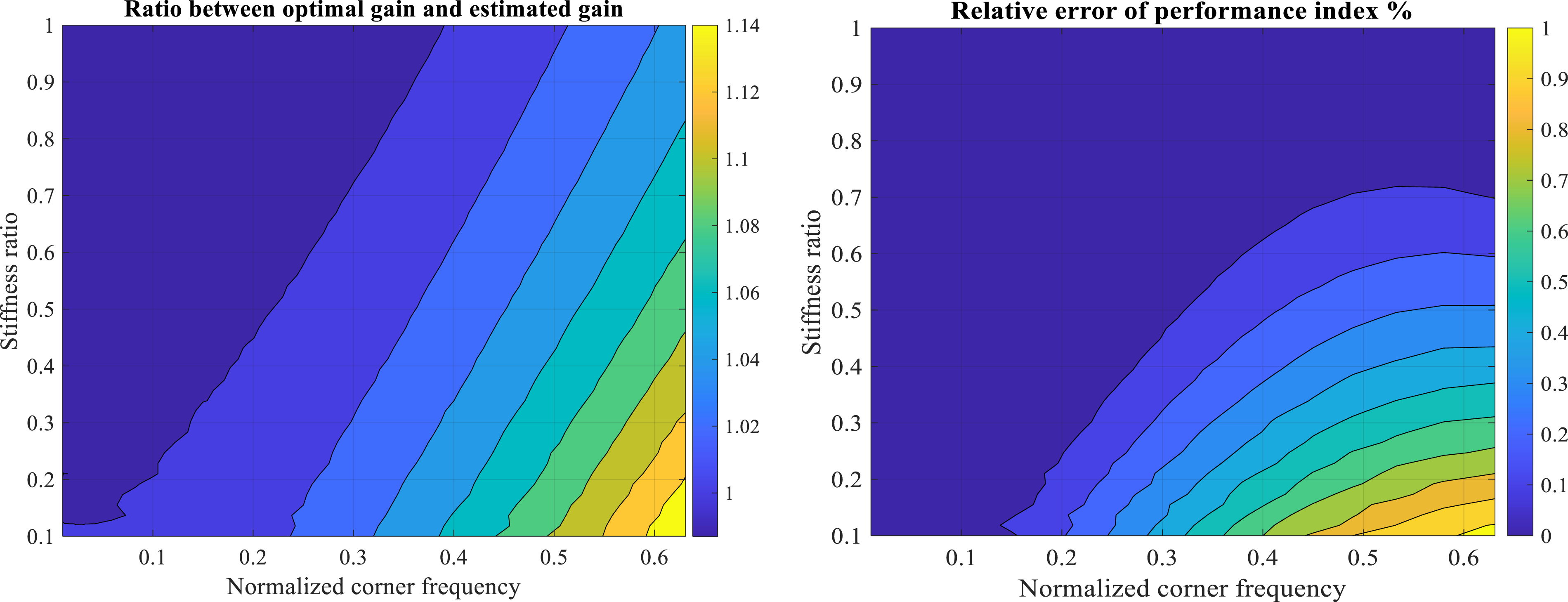
In order to better understand how the proportional gain

Note that there exists a pair of complex zeros and a pair of complex poles as in the case of classical integral force feedback control. The distance between the location of zeros and poles is often used as a performance index to characterise the control effectiveness. When the proposed controller is used, the stiffness ratio
Since the proposed active damping device can be fully represented by a mechanical network (given idealised force sensors and actuators are employed and

The phase margin is calculated as:

Figure 3 plots the phase margin of the coupled system against the stiffness ratio Phase margin of the coupled system when the optical settings are applied.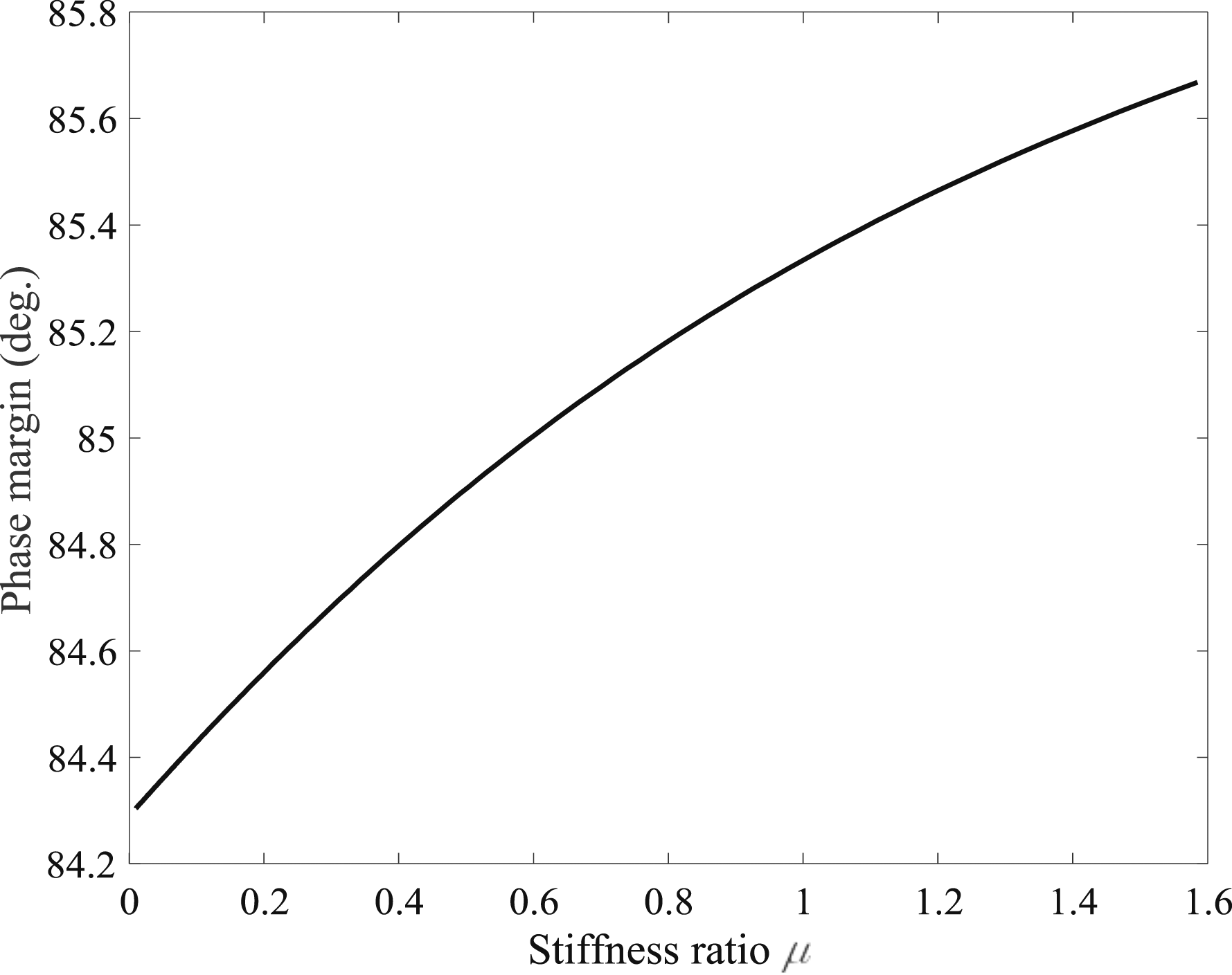
In practice, the proposed controller is implemented in a cascade way. The control plant The frequency response function of (a) the control plant, (b) the open-loop gain, and (c) magnitude of the performance index for different values of 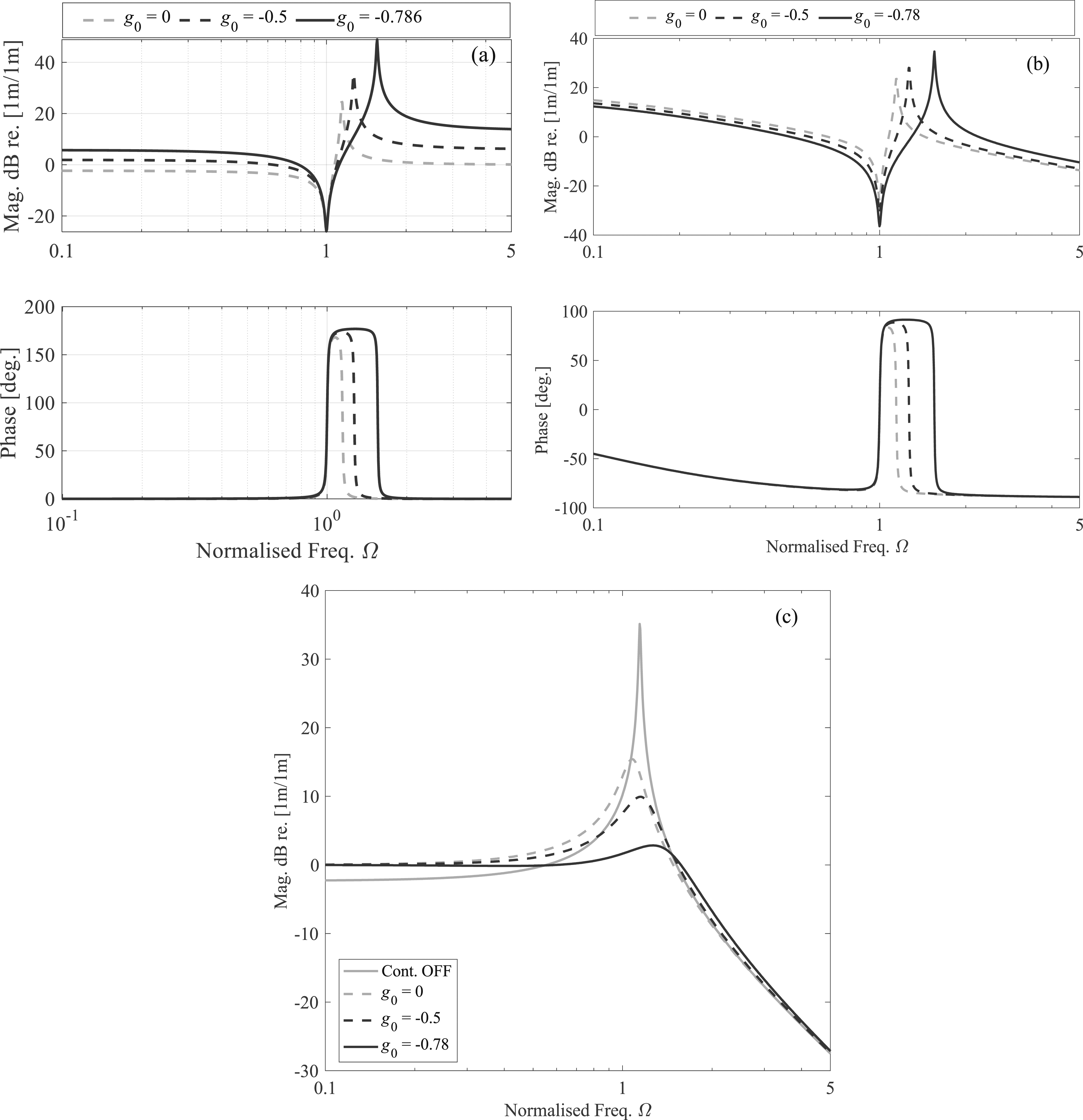
In practical applications, the effective stiffness ratio

In the following, the controller effectiveness of the proportional term is illustrated. Figure 4(a) compares the control plant of the considered system when the gain
In Ref. 21 a proportional controller is considered in order to boost the control performance of integral force feedback controllers. It is implemented as a feedforward term, while the proposed controller takes an opposite architecture where the proportional term is introduced in the feedback path. In order to compare the two controllers, the performance index introduced in this manuscript, that is, the magnitude of the normalised driving-point receptance
With the controller in Ref. 21 the performance index is written as:

Under the


The performance index decreases when the proportional gain
In order to better understand the physics behind, the normalised control plant associated with Ref. 21 is derived:

As can be seen, the zeros of the control plant move leftwards when the parameter
Figure 4(b) plots the open-loop gain of the system for the three values of
Figure 5 compares the resultant root loci of the system when applying different feedback gains of the proportional term. In consistence of the control plant as shown in Figure 4(a), the location of the poles moves away from that of the zeros when g0 approaches to −1. As such that the most achieved damping also increases with a decrease of g0 in the negative direction. When impulse excitations are concerned, it helps reduce the setting time of the transient response of the system. Note that the optimal gains for achieving the maximum damping and the minimal maximum steady state response of the structure are different as illustrated in Refs. 15,16. The root locus of the system for different g0.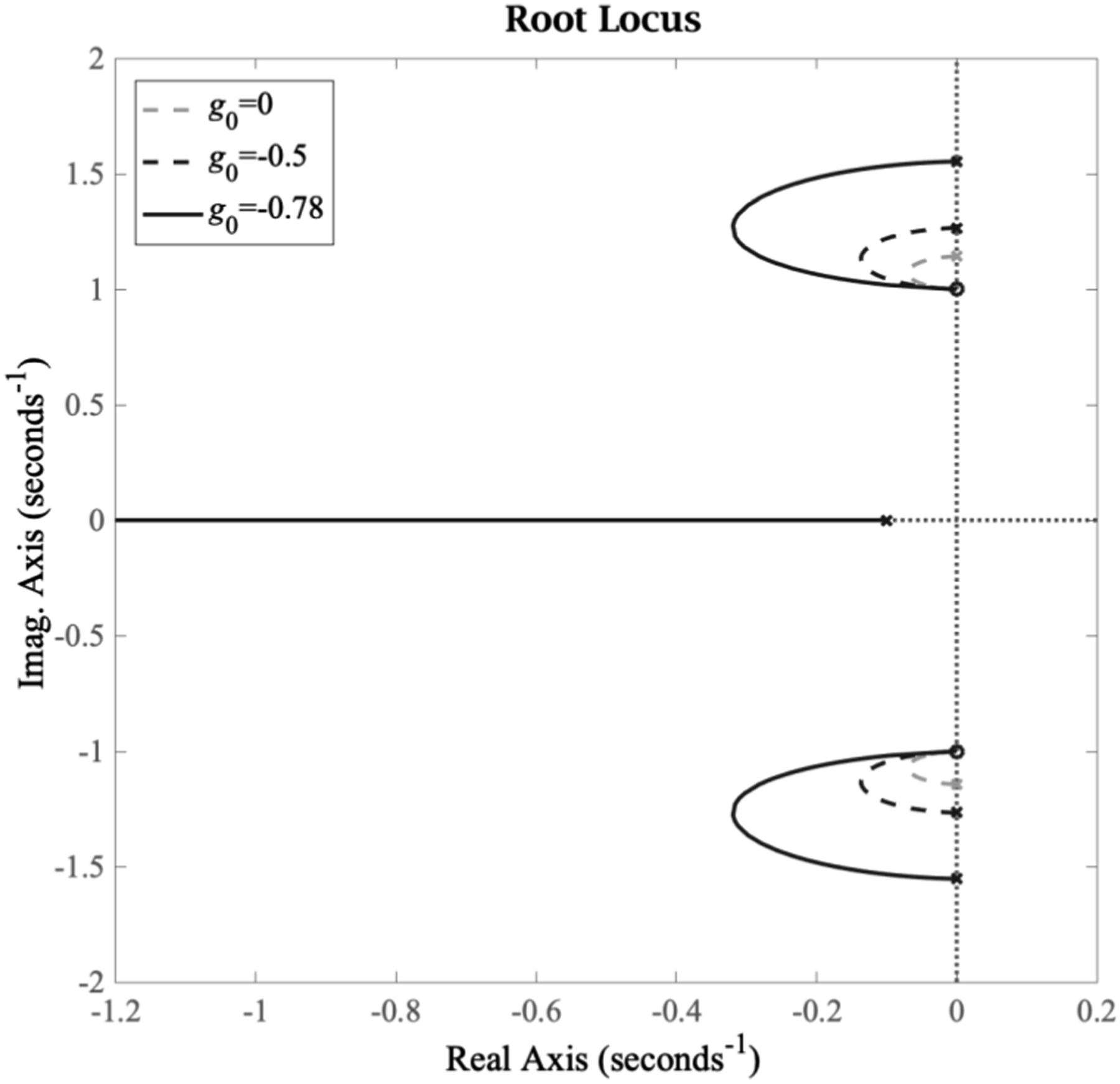
Experimental validation
Figure 6 shows the test bench used for experimental examination. The primary structure is a cantilever aluminium beam with the dimensions 45 cm*3 cm*0.3 cm (length*width*thickness). Two voice coil actuators (AVM24-10) are mounted at the free end of the cantilever beam. One of them is used to introduce the disturbance force and the other one is used to deliver the control force. According to the Lorentz law, the force delivered by an ideal voice coil actuator (its mass and damping are neglected) can be regulated by
3
: The experimental test set-up: (1) cantilever beam, (2) eddy-current sensor (ECL101), (3) force sensor (PCB 221B02), (4) voice coil actuator (AVM24-10), (5) MicroLabBox, (6) current amplifier (ADD-45N), and (7) ICP conditioner (PCB 482C05).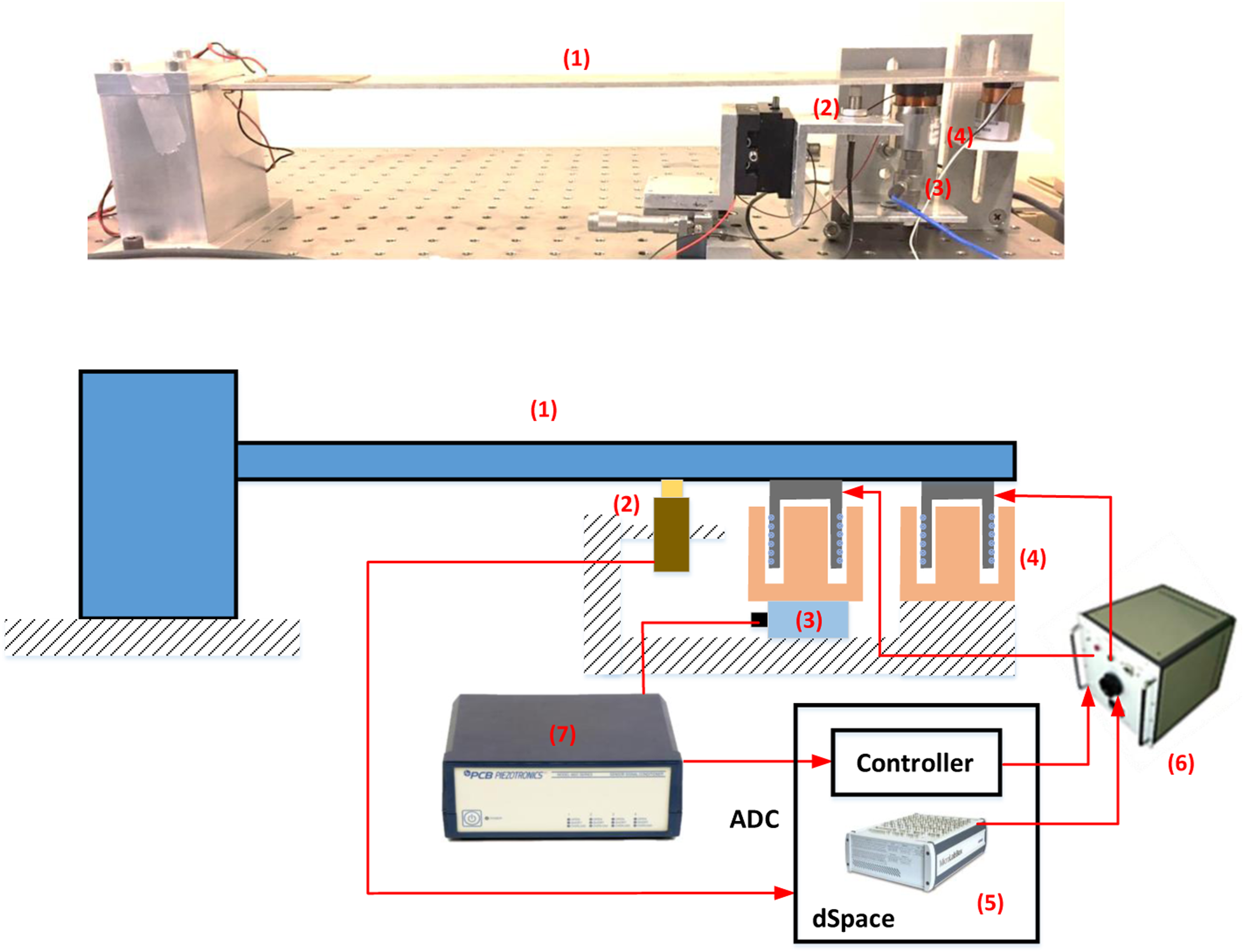

In the theoretical analysis, the transfer function between the displacement and the disturbance force was chosen as the performance index. Therefore, an eddy-current sensor (ECL101) was used to measure the tip displacement of the beam, which is installed close to the voice coil actuators. In this study, only the first bending mode of the beam is considered such that the single-mode beam can dynamically represent a linear SDOF system. The block diagram of the control scheme is depicted in Figure 7. Underneath the control actuator, a force sensor (PCB 221B02) is installed in order to measure the transmission force and provide the feedback signal. However, additional damping is induced by the voice coil actuators (the eddy-current effect and air viscous damping effect), which violates the low damping assumption of the primary structure. Thus, a negative damping control loop was implemented in order to eliminate the total inherent damping of the system. This was achieved by positively feeding the tip velocity signal back to drive the voice coil actuators. The velocity signal is obtained by passing the displacement signal measured by the eddy-current sensor through a first-order high-pass filter with a corner frequency of 500 Hz. The high-pass filter is used in order to avoid the over-injection of the sensor noise in the high-frequency range. The feedback gain of this negative damping loop is denoted as The configuration scheme of the experimental set-up.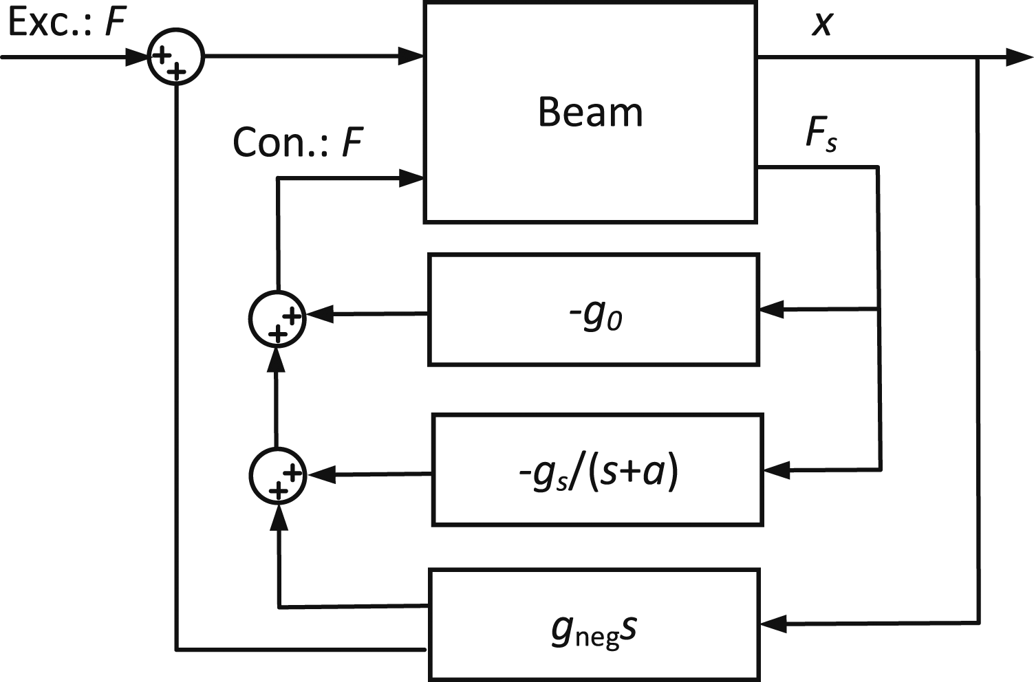
A dSpace MicroLabBox system was used both for the data acquisition and the control implementation. The control scheme was implemented in the Matlab Simulink environment and then downloaded to the processor unit of the MicroLabBox system. The control scheme was updated at a sampling frequency of 10 kHz, and the measured data were recorded at the same sampling frequency. A current amplifier (ADD-45N) was used to drive the voice coil actuators.
For the considered set-up or future applications, the optimal value of the control gain can be calculated with the knowledge of the effective stiffness ratio between the actuator and the host structure. Practically, the stiffness ratio can be directly estimated by performing a measurement of the control plant. Based on the measured control plant, the locations of the zeros and the poles as well as the DC gain can be extracted. Before further proceeding, one should also pay attenuation to the modal interactions between the targeted mode and the other adjacent modes. For the considered set-up, the first mode of the cantilever beam is chosen for the experimental validation. In such a case, the contributions from the higher modes can be characterised as a quasi-static gain,
24
which needs to be taken into account when estimating the effective stiffness ratio. More precisely, the DC gain defined as the response of the control plant at 0 Hz, that is,
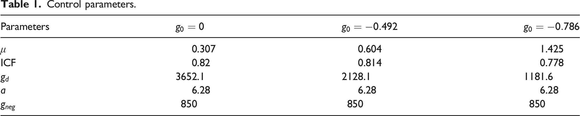
Finally, the identified stiffness ratio
The optimal control parameters for different values of
Figure 8(a) plots the frequency response of the control plant when The frequency response of (a) the control plant and (b) magnitude of the performance index for different values of Control parameters.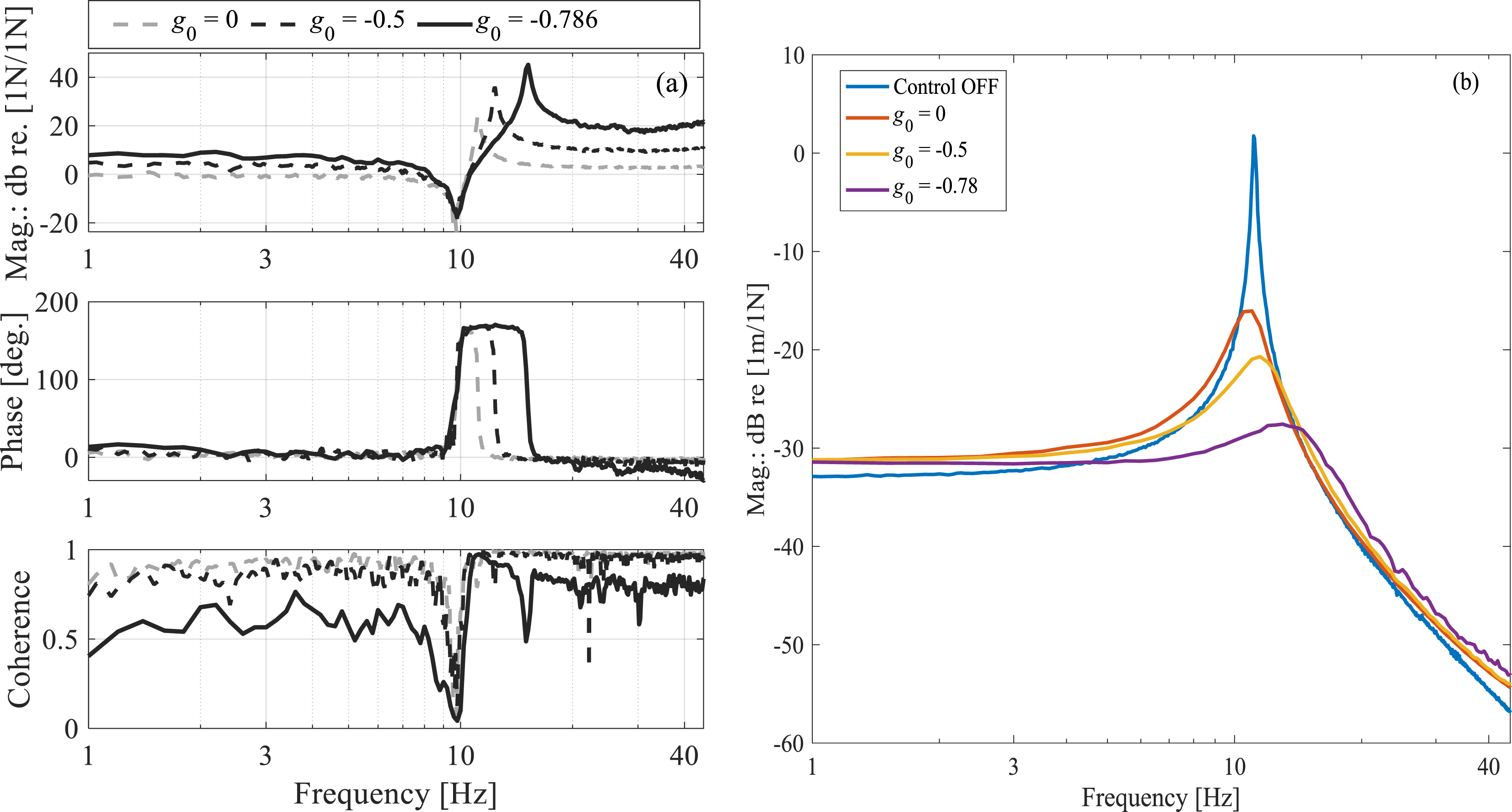
Conclusion
This paper discusses an enhanced integral force feedback controller which consists of a first-order low-pass filter and a proportional term. The physics behind is explicitly explained via an equivalent mechanical model. The first-order low-pass filter mimics the dynamic behaviour of a pure mechanical network which comprises a spring and a damper connected in parallel, while the proportional term plays the same role as a mechanical spring connected in series with the inherent actuator spring. The active damping is provided essentially by the first-order low-pass filter where the cut-off frequency is required to be smaller than the target frequency to be damped. By cascading the proportional controller, a relatively large stiffness ratio can be implemented given that the associated gain is properly tuned. Compared with the classical IFF controller, the proposed control can further improve the vibration mitigation performance and also suppress the low-frequency saturation induced by the integration operation. The numerical study, where the optimal feedback gain is calculated given a fixed pair of stiffness ratio and the cut-off frequency of the first-order low-pass filter, shows that the optimal feedback gain can be taken the same as that of the IFF controller in the sense the performance index is concerned. The obtained results were found to be in excellent agreement with the experimental tests. With these results, one can envision to develop a simple analogue electronic control system for a collocated actuator-force sensor pair such that the device would be compact enough for smart structure applications.
Footnotes
Acknowledgements
The financial supports from the Science Fund Program for Distinguished Young Scholars (RLZY20231001-10), Zhujiang Talent Plan (2021QN02Z097), the Specialized Fund for the Basic Research Operating Expenses Program of SYSU (23hytd004), and National Key R&D Program of China (Grant No. 2022YFC2204000) are gratefully acknowledged.
Declaration of conflicting interests
The author(s) declared no potential conflicts of interest with respect to the research, authorship, and/or publication of this article.
Funding
The author(s) disclosed receipt of the following financial support for the research, authorship, and/or publication of this article: This work was supported by the Zhujiang Talent Plan (2021QN02Z097), National Key R&D Program of China (2022YFC2204000), National Natural Science Foundation of China (RLZY20231001-10), and Specialized Fund for the Basic Research Operating Expenses Program of SYSU (23hytd004).
Appendix
In this appendix, it is to prove that the systems sketched in Figure 1(a) and (b) are dynamically equivalent.
(a) the sketch of the active system and (b) its mechanical representative.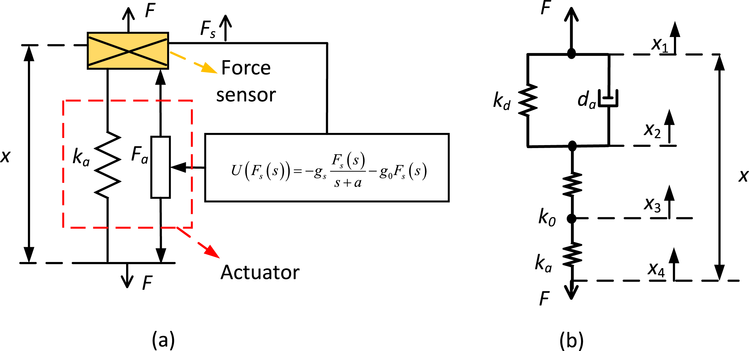
Figure A.1(b) depicts a pure mechanical system which consists of several springs and dashpots as well as an inerter. Under the excitation force denoted by
Expressing the relative motion in terms of the transmission force
According to the control law, the governing equations of the system shown in Figure A.1(a) can be expressed as:
Comparing equation (A.7) with equation (A.8) and one can find the equivalence between systems shown in Figure A.1(a) and (b). The feedback gains and their corresponding mechanical components are thus related by equation (A.9):