
Abstract
In this research, the effects of two different types of in-track countermeasures on ground-borne vibration from underground railways are investigated. First, the influence of new type of supports is investigated, in which the rotation of the rail is partially or fully restrained. Second, a different simple local resonator is considered consisting of masses on springs placed at fixed spacing between the supports. To investigate the effects of these countermeasures, a numerical model is developed consisting of two sub-models: the first sub-model is an excitation model in which the track is modelled as an infinite beam on discrete supports connected to rigid foundation, for the calculations of forces transmitted to tunnel bed. The beam is analysed under the action of a number of axle masses with harmonic excitation induced through relative displacement between the un-sprung axle mass and the beam using a pull-through roughness. This first sub-model employs the dynamic stiffness method to perform the calculation. The second sub-model accounts for a tunnel embedded in a half space and is used to calculate the responses in the free surface with the input forces taken from the first sub-model after transformation to the wavenumber domain. The second sub-model is based on the well-known Pipe in Pipe (PiP) model. The discontinuously-supported model used in this work is verified using a continuously supported model. The effects of the suggested countermeasures on vibration mitigation are explored via parametric analysis that shows the impact of the added rotational stiffness, resonators’ natural frequency and the resonators’ mass. The results show for the parameters considered that using the rotation restrained support can effectively reduce the ground-borne vibration levels by up to 20 dB for low frequencies. Furthermore, the use of local resonators can reduce the ground-borne vibration by 4–10 dB for frequencies in the range 20–200 Hz.
Keywords
Introduction
Ground-borne vibration propagates through the ground as a wave-form and can be transmitted into foundations of surrounding structures causing vibration of buildings. 1 Vibration of buildings can result in negative impact on residents and sensitive equipment.2–7 Vibration is perceived as ground-borne vibration in nearby buildings within the low frequency range of 1–80 Hz and as ground-borne noise within the range 1–250 Hz. 8
To reduce these undesired effects of underground trains, many researchers studied the ground-borne vibration mitigation countermeasures. For instance, Liu et al. 9 provided a list of design procedures for mitigating ground vibration caused by trains, which were assessed by metamaterials. Countermeasures can be introduced in the source, that is, the track, see 10–15 for example. They can be introduced in the transmission path, between the source and receiver, see 16–19 for example. Vibration countermeasures can also be introduced in the receiver, that is, the building, see 20 for example. More information about the countermeasures is presented in the next paragraphs.
One method to reduce ground-borne vibration at the source is by using floating slab tracks 10 in which the slab is supported by slab bearings. A number of researchers investigate the effectiveness of using floating slab tracks in reducing ground-borne vibration such as Cui et al. 11 who confirm that the use of floating slabs reduce the transmitted forces for excitation frequencies greater than 15 Hz. Alsharo et al. 12 state in their work that the use of softer railpads would reduce the vibration intensity on the free surface by about 10 dB for frequencies range of 40–200 Hz. Zeng et al. 13 demonstrate that the use of rubber composite sleepers and concrete sleepers can reduce ground-borne vibration peak acceleration by 38.35% to 66.23% and can lower vertical vibration by 63.12% to 96.09%. Wei Li et al. 14 proposed a shear-type multi-band tuned rail damper made up of internal mass bars wrapped inside rubber like materials which might enhance track decay rate (DR) at frequencies above 80 Hz with a maximum increment of 5 dB/m and 9.3 dB/m in vertical and lateral directions, respectively. Cui et al. 15 inserted locally resonant phononic crystals regularly into the concrete sleeper that caused a significant decrease in the vibration transmission at the locally resonant frequency up to 35 dB.
Investigating vibration countermeasures in the transmission path includes the work of Younesian et al. 16 who found that using multiple trenches reduce the amplitude of train-induced vibration by 6 to 13 dB. Ouakka et al. 17 suggest using seismic metamaterial to enhance the vibration attenuation levels of existing mitigation measures by around 10 dB. In Qu et al. work, 18 the insertion loss of vertical acceleration achieved 18.0 dB by applying an engineered metabarrier. Albino et al. 19 suggest applying ‘phononic’ crystal and metamaterial principles to vibration protection based on buried vertical structures placed in a periodic manner between the source and the receiver. Sadeghi et al. 20 explore the effect of injection of a continuous thin layer of soft materials into the soil under adjacent receivers.
Recent researches on ground-borne vibration put more focus on the effect of countermeasures to reduce ground-borne vibration 21 to avoid the issues of uncertainties associated with absolute predictions. 22 In this paper, the authors expanded their initial investigation 23 regarding two different types of in-track countermeasures: the rotational stiffness introduced with the usual vertical stiffness and a different simple local resonator. The present work carries out a parametric analysis that takes into account the additional rotational stiffness, the resonator’s natural frequency, and the resonator’s mass to investigate how the suggested countermeasures would influence ground-borne vibration from underground railways.
The idea of rotation restraint was inspired by the authors from the rail-web fastening system which provides a small rotational restraint compared to the conventional under-rail pad. The target of investigating such measure is to explore the potential of designing and developing a new type of rail support to reduce ground-borne vibration especially at the low frequency range, that is, below 80 Hz and around the track resonance frequency. The novelty of the current work lies on the development of numerical models and the investigation of these two countermeasures to reduce ground-borne vibration from underground railways.
The rest of this paper is presented as follows. In the second section all models used in this work are described. First, the dynamic stiffness method was implemented to model the dynamic excitation of a train with three coaches on the top of a track discretely supported by springs having a vertical stiffness only. The Pipe in Pipe model (PiP) is used later to calculate the response directly above the train in the free surface and a continuously supported excitation model is described in order to verify the discontinuously supported excitation model later. Then, another model based on the dynamic stiffness method is used to account for a beam discretely supported by supports having vertical stiffness and rotational stiffness together. Finally, a model with a simple local resonators used for vibration mitigation is illustrated which consist of periodically arranged local resonators simplified as vertical stiffness, viscous damper, and a mass. The results are shown and discussed in the third section, while the conclusion is given in the last section.
Models discerption
In this section ground-borne vibration from an underground railway tunnel has been simulated by using a complete model that accounts for the effect of the train, track, tunnel, soil, and their interaction. The model is then employed in order to investigate the ground-borne vibration mitigation by the introduction of the rotation restrained support and the local resonators. Also the vertical support model, that is, conventional model is modelled for comparison purposes in two ways to help with verification of models; once as discretely supported track and once as continuously supported track.
Vertical support model (discretely supported and continuously supported)
The model developed in this work, is illustrated in Figure 1, and consists of two sub-models; the excitation model in which the track is modelled as an infinite beam on discrete supports connected to rigid foundation, that is, tunnel bed using the dynamic stiffness method, to calculate the forces transmitted to tunnel bed. Later another sub-model accounted for a tunnel imbedded in a half space is used to calculate the responses in the free surface. For this purpose, the well-known Pipe-in-Pipe model that simulates a tunnel embedded in the ground is used.
8
Modelling underground rail track summary.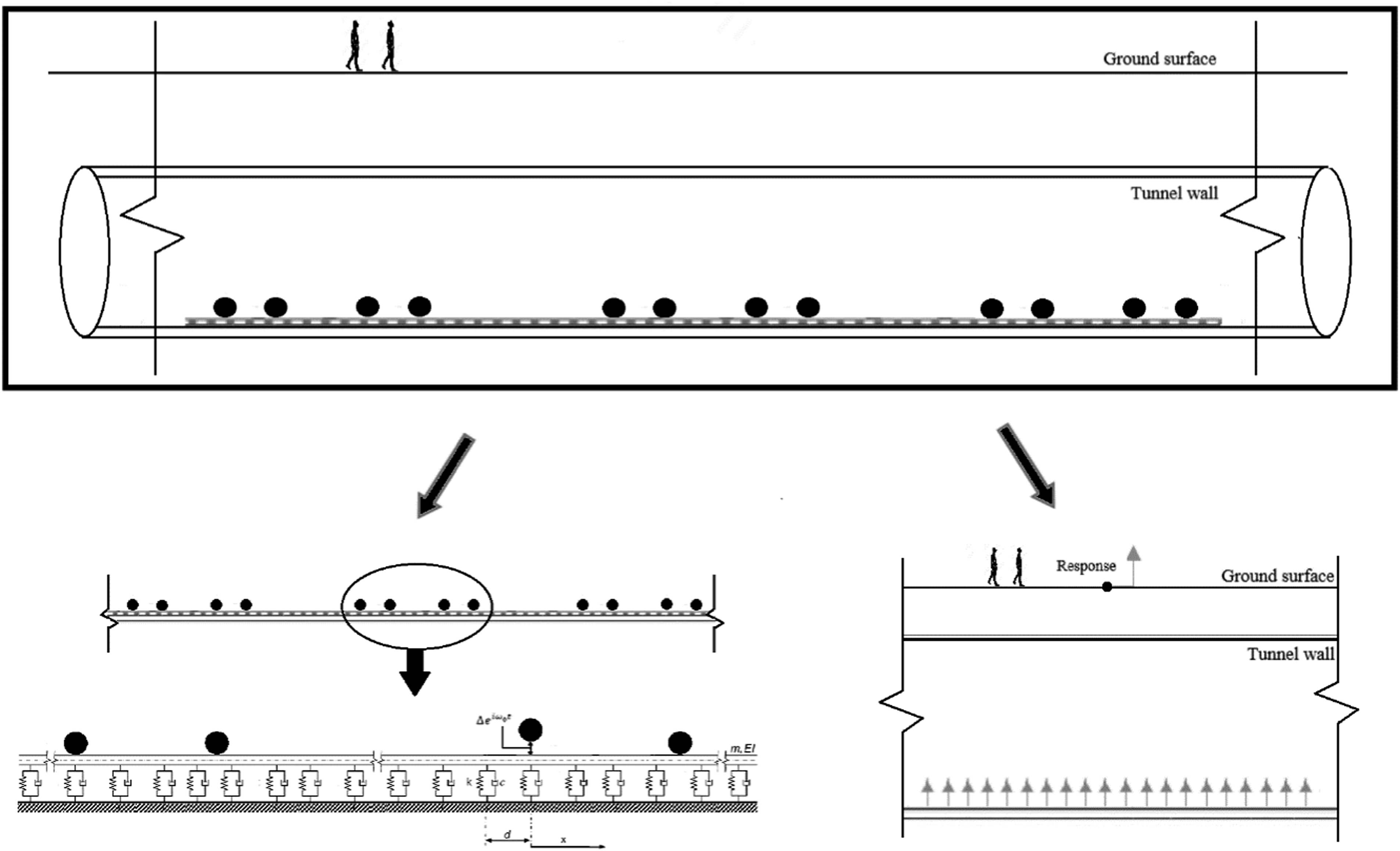
The discretely supported track model
In order to investigate the influence of adding in-track countermeasures on track’s dynamics, a frequency domain based model has been used where the rail was modelled as an Euler-Bernoulli beam, with mass per unit length m and bending stiffness for one rail EI. The rail is discretely supported on rail pads with spacing of d, and modelled as Kelvin-Voigt visco-elastic model. The rail beam is under the action of N axle masses Discretely supported model under the action of N axle masses with harmonic excitation induced through relative displacement 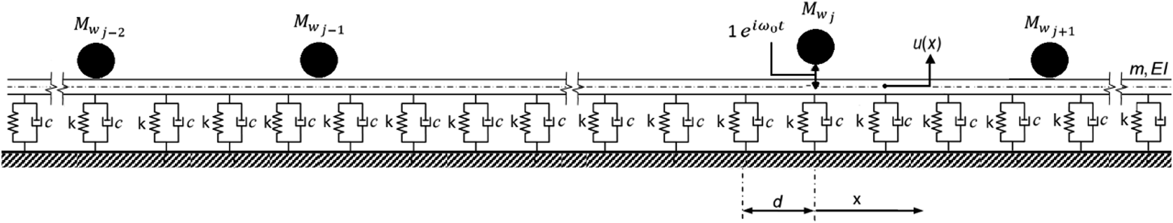
The dynamic stiffness of rail pads will be calculated as a function of the dynamic displacement in the frequency domain using equation (1).

As shown in Figure 3, the rail is discretized using two-nodded elements with L length and two degree of freedom for each node, that is, vertical translation and rotation. The beam is discretized for number of elements n = beam length/L such that the total number of nodes is n + 1 and the total number of degrees of freedom is 2 (n + 1). The rail beam discretisation and the ith element’s degrees of freedom.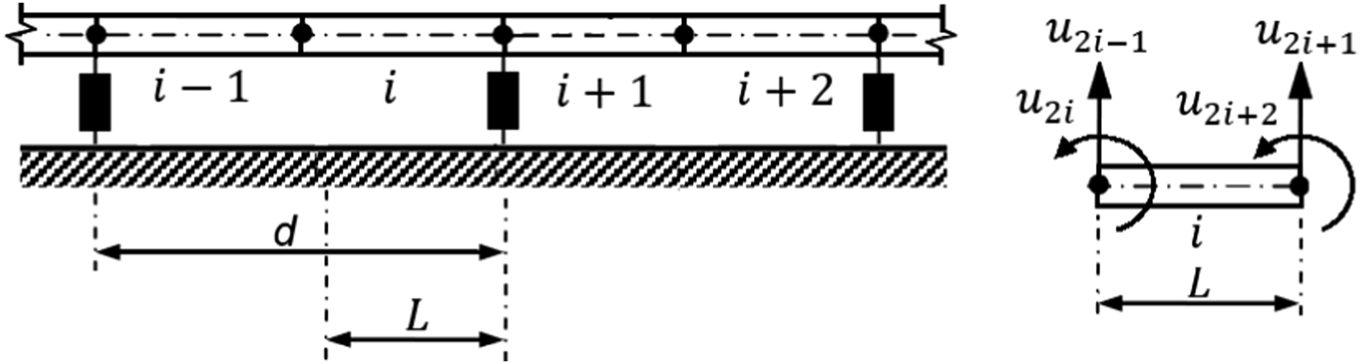
First, in order to allow the dynamic stiffness matrix expression shown in equation (2) to calculate the dynamic displacement

A unit amplitude dynamic load

Repeating the previous step for all un-sprung axle masses gives the N × N transfer matrix

The induced relative roughness under the un-sprung axle mass

Substituting


Then, forces transmitted to the rail under each un-sprung axle masses are inserted in the corresponding degree of freedom elements in

Considering that

For joining the track to the tunnel purposes later, the forces transmitted to the tunnel bed through railpads The forces transmitted to tunnel bed through supports 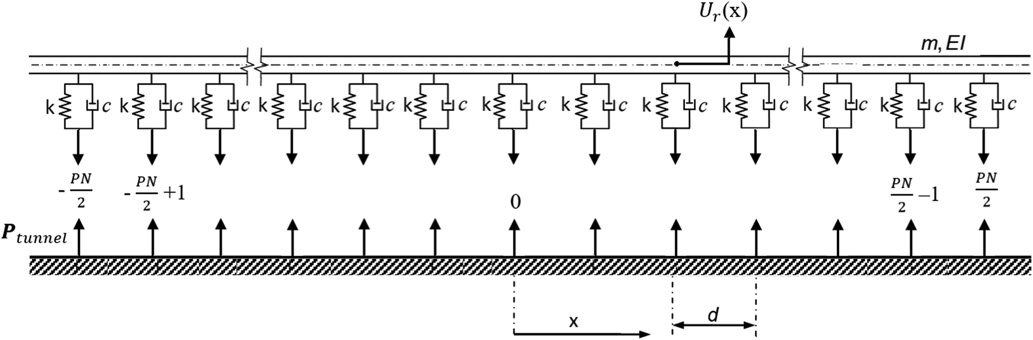


This step is essential since the PiP model will be used later to give the transfer function which accounts for the tunnel-soil interaction, the data should be in wavenumber domain as the PiP gives the results in wavenumber domain.
The continuously supported track model
The rail was modelled as an Euler-Bernoulli beam, with mass per unit length m and bending stiffness for one rail EI. The rail is continuously supported on rail pads represented by a continuous layer of springs with stiffness per unit length k and a viscous damping factor c
28
The rail beam under the action the same loads as the previous model as shown in Figure 5, u(x) is the beam response at distance x and Continuously supported model under the action of N axle masses with harmonic excitation induced through relative displacement 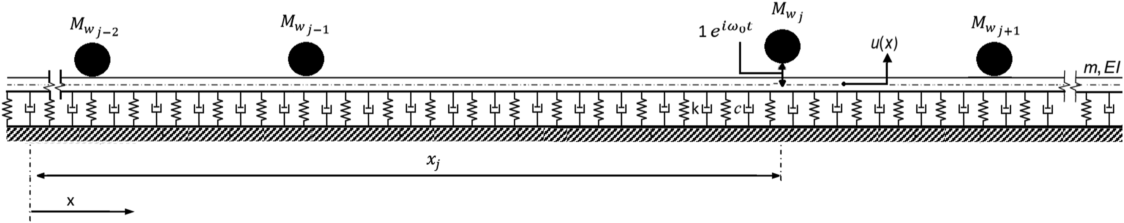
The dynamic displacement along the beam length can be calculated by solving the generated differential equation (13) numerically using Fourier transformation as in 29.


And the solution of equation (13) is shown in equation (15), that is, the dynamic displacement u(x) at any x.

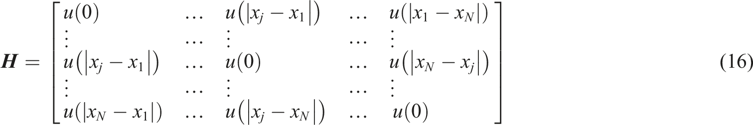
Using equation (15) the N × N transfer matrix The N un-sprung axle masses and their locations.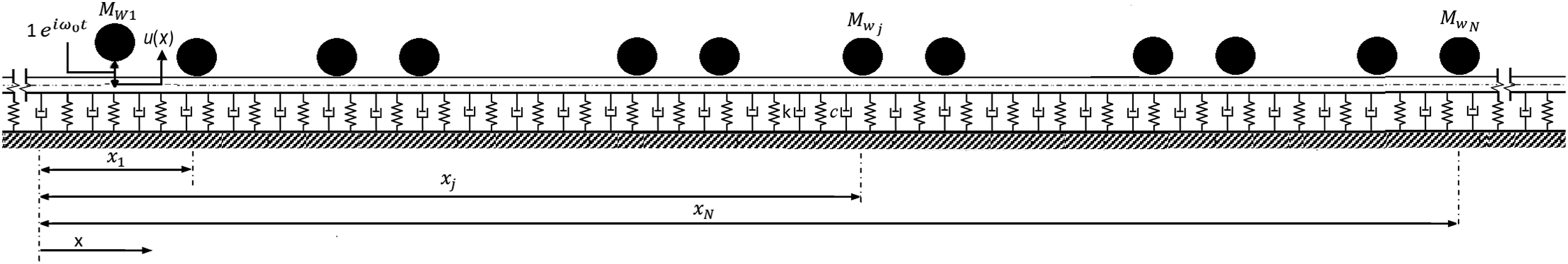
The forces transmitted to rail under all un-sprung axle masses
Equations (13) and (14) are transformed from space-time domain to wavenumber-time domain using Fourier transformation as shown in equations (17) and (18) to give the dynamic displacement under the un-sprung axle masses shown in equation (19) in wavenumber-time domain.


The forces transmitted to the tunnel bed

The track-tunnel model
The Pipe-in-Pipe (PiP) model is a computationally efficient model for calculating vibration from underground railways. The original version of PiP30–33 is based on a model that accounts for a tunnel and its surrounding soil as two concentric pipes; the inner pipe accounts for the tunnel wall and the outer pipe accounts for the surrounding soil. The PiP model was further developed to model ground-borne vibration from a tunnel embedded in a half-space or layered half-space by using the fictitious force method. 8 In this method, the near-filed vibration from the original version of PiP is regenerated by forces in a model of a half-space or layered half-space, and then used to calculate vibration in the far-field. This is based on the assumption that the near-field vibration is not influenced by the existence of layers or half-space. This version of PiP accounting for a tunnel embedded in a half-space or layered half-space is verified against an FE_BE model 8 of the same problem and excellent matching is observed, with significant advantage for the PiP model regarding the running time and requirement of computational resources. The developed version of PiP accounting for a tunnel embedded in a half-space, and accounting for the loads of trains moving on slab tracks due to roughness/irregularity of tracks, is available as freeware for practicing engineers and researchers with interest in the field. 34 This developed version of PiP models a train as infinite number of un-sprung masses to represent the axles of the train. A pull-through roughness is used to generate the excitation source. This provides an additional gain on the computational efficiency without losing on the accuracy 24 when calculating the stationary vibration due to a train moving with velocity with value much less than the critical velocity of the track.
In this paper the PiP model is used to calculate the transfer function of the vertical displacement at any selected point in the soil or at free-surface for a roughness excitation of a unit value (i.e. white noise) for a train running on a track in a tunnel embedded in the ground. The parameters of tunnel and soil are taken from literature. 12
First, the soil transfer function

Then, the displacement response in the surface

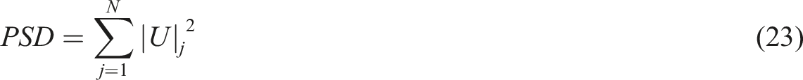
These calculations will be repeated N times in order to find the response in the surface due to exciting each one of the un-sprung axle masses alone. Finally, the Power Spectral Density PSD can be calculated at
Rotational-restrained support model
As shown in Figure 7 all elements of this model have been modelled as previous one, that is, vertical discretely supported model, except the supports which have been replaced with supports that prevent the rotation, that is, have a vertical stiffness k and rotational stiffness Rotation restrained support model under the action of N axle masses with harmonic excitation induced through relative displacement 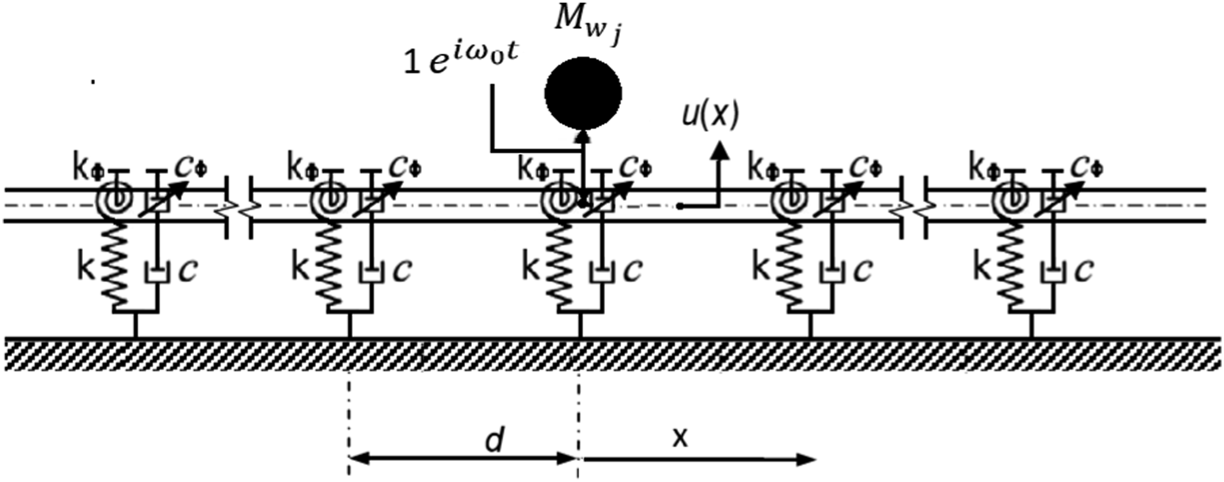
The dynamic stiffness method has been used to solve this model in a similar way that the previous one has been solved. The dynamic rotational stiffness magnitude has been added to the accounted element in the global stiffness 2 (n + 1)×2 (n + 1) matrix

The local resonators model
Periodically arranged local resonators have been added in the midway of the supports to prevent the vibration waves from propagating forward. The local resonator is simplified here as vertical stiffness The local resonators model under the action of N axle masses with harmonic excitation induced through relative displacement 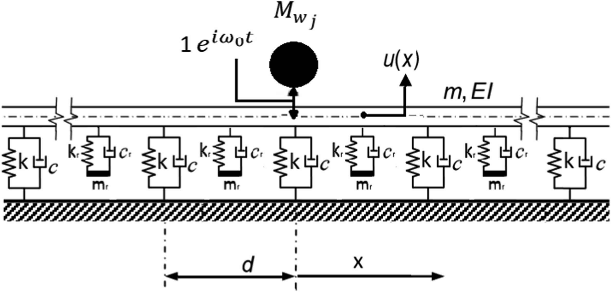
The dynamic stiffness of the local resonators can be calculated in the frequency domain using equation (25).

Results and discussion
The parameters used for the numerical analysis are for 60E1 rail type (Rail profile 60 E1: manufactured according European Standard EN 13674-1) with a mass of 60.2862 kg/m and bending stiffness EI of 8.8 MN.m2, rail pad spacing d = 0.6 m, rail pad stiffness k = 20.818 MN/m/m and rail pad damping coefficient c = 7.0853 kN.s/m/m. The train used in this paper have three coaches, each with four axles, an un-sprung axle mass Mw = 3127 kg, a distance of 2.2 m between axles on the same bogey, a distance of 10.8 m between the bogey centres on one coach and a distance of 4.8 m between the back axle in one coach and the front axle of the next coach.
Discrete model verification
The dynamic behaviour of the rail beam has been modelled twice, assuming the railpads are discretely supported in the first model and continuously supported in the second model to verify the discretely supported one.
As described in section 2 both beams were under the action of 12 axle masses (3 coaches) and with harmonic excitation induced through the relative displacement Power spectral density for the displacement at the free-surface plotted against the frequency above the train at x = 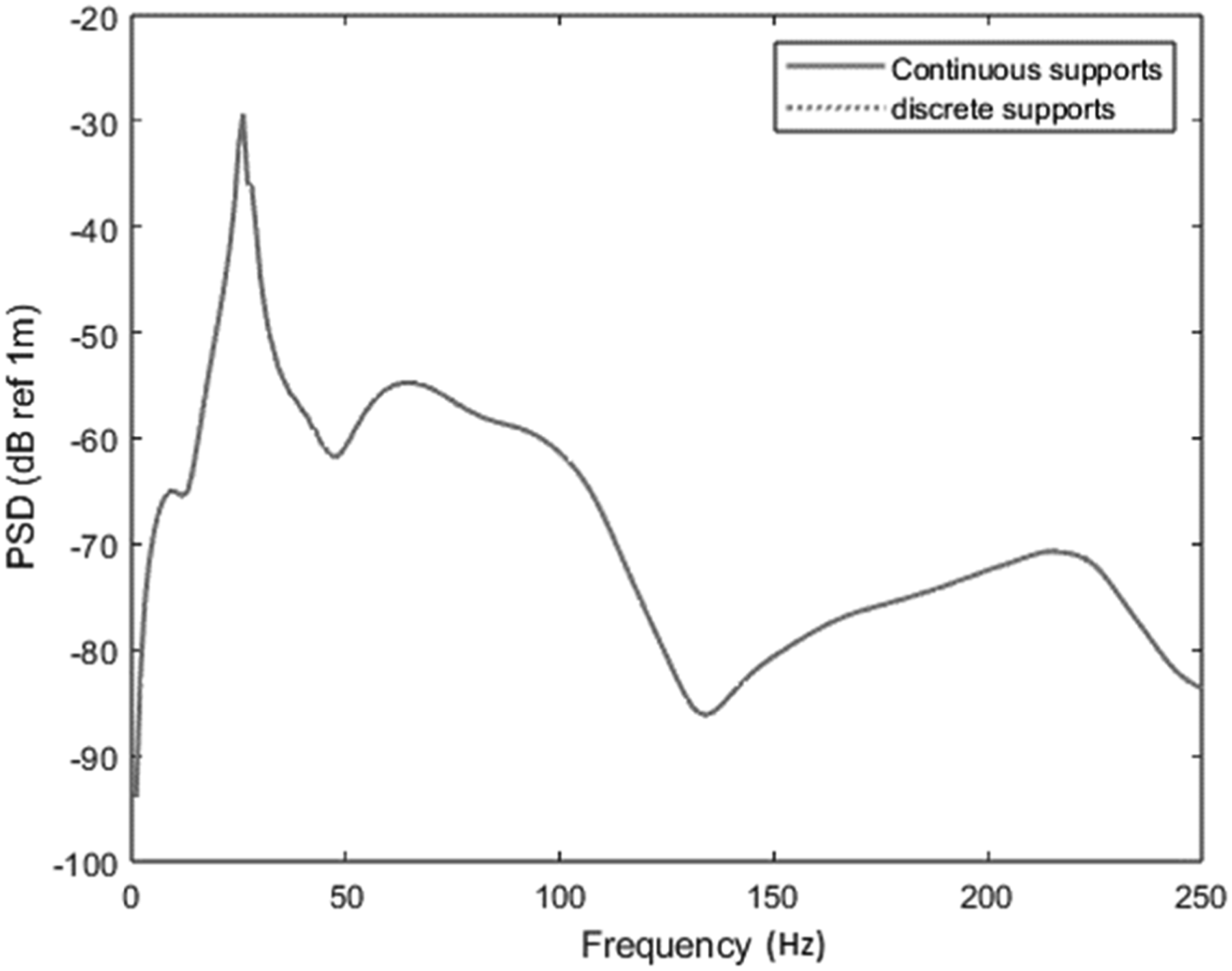
However, the axle-track system at resonance can be presented as described in Ref. 36 as a single degree of freedom system with a mass equal to the un-sprung mass of train with the part of the rail that moves up and down with the axle and a stiffness equal to the track stiffness underneath the axles as in equation (26).

Substituting the previous model parameters in equation (26) and finding the real part of the largest positive root will gives the resonance frequency of the system
To further verify the findings, a comparison is made between the Power Spectral Density (PSD) data obtained using the standard PiP model and the discretely supported model proposed in this study. Please refer to Figure 10 for the results. It is important to mention that the PiP model considers an infinite train with an unlimited number of axles at a constant distance between. The model proposed in this study utilises a finite train. However, in the case of an infinite train, a fixed distance of 5.5 m is used between the axles. This distance is calculated as the average spacing by dividing the distance between the first and last axle by the number of spaces between axles. The choice of spacing and whether the train is infinite or finite affects the overall vibration levels, but has a minimal impact at frequencies below 100 Hz. The low-frequency range is crucial for ground-borne vibration and ground-borne noise due to the predominant presence of vibration energy within this range. However, a better match can be achieved by unifying the damping types in both models, that is, hysteretic damping is considered in the PiP model, while viscous damping is considered in the discretely supported model used in this work. Power spectral density for the displacement at the free-surface plotted against the frequency above the train at x = nL/2 using ___: PiP model, …: discretely supported model.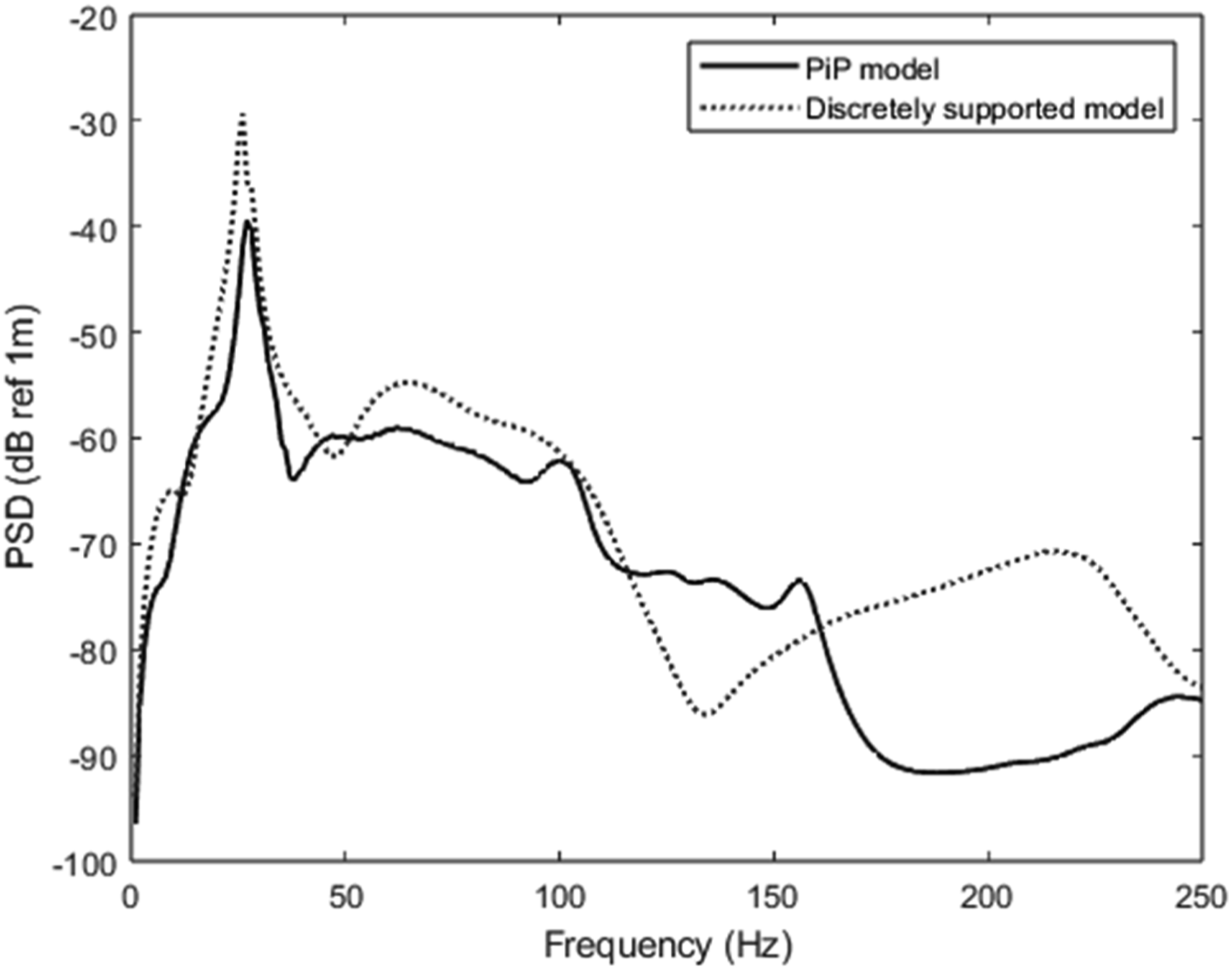
Effect of rotation restrained support on ground-borne vibration mitigation
The rail beam has been modelled as a discretely supported beam, and the described rotational stiffness has been added with three different values to present supports with low, medium and high rotational stiffness, that is, rotational stiffness
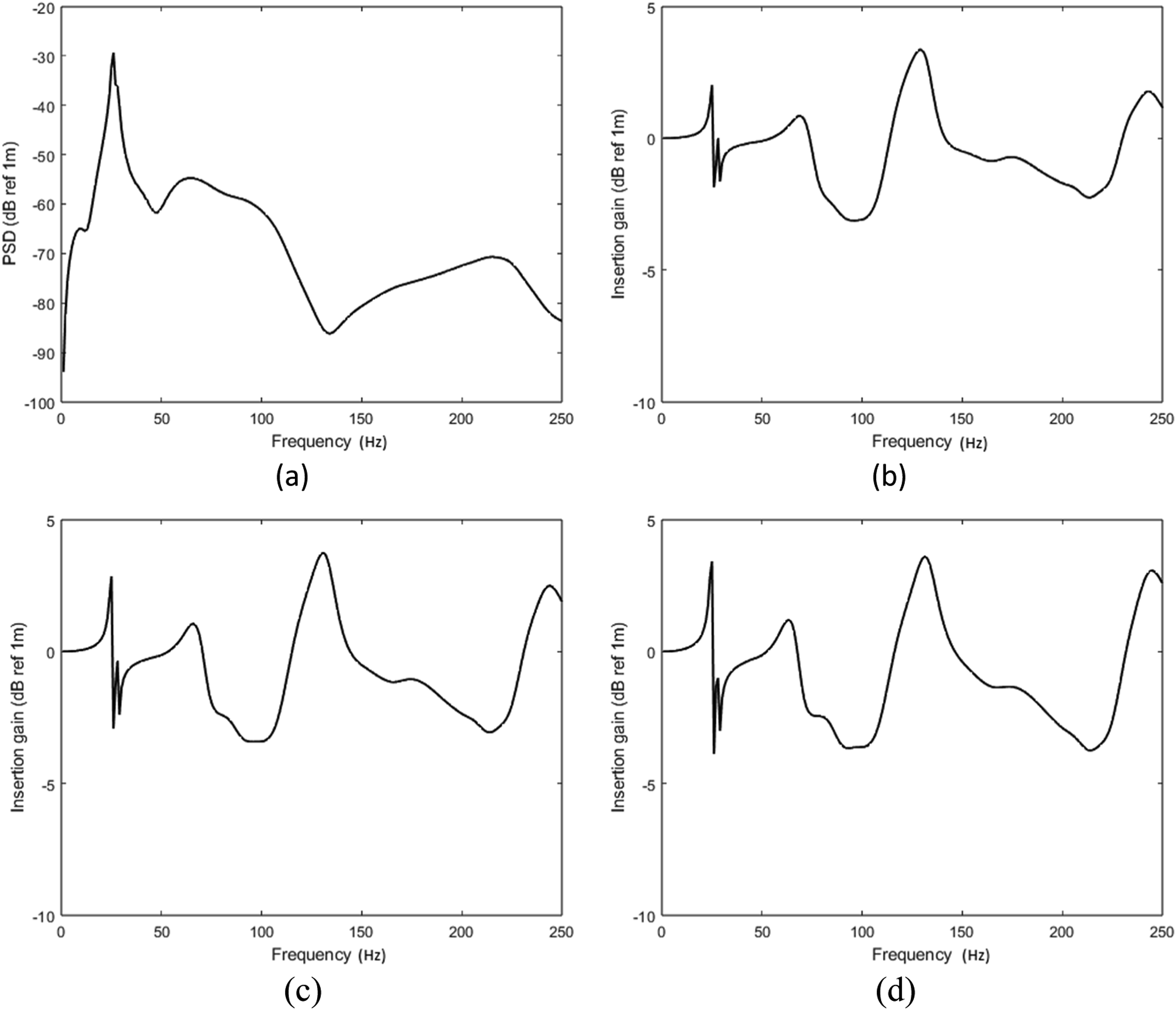
The investigation focuses on quantifying the reduction of vibration by computing the insertion gain

As can be seen in Figure 11, the mitigation level of this countermeasure tends to increase with the increase in the rotational stiffness for low frequencies. In general, the results show that using the rotation restrained support can effectively reduce the ground-borne vibration levels at a low-frequency range of 1–30 Hz and by around 20 dB ref 1m when using supports with high rotational stiffness as can be seen in Figure 11(d), which can be considered as remarkable results for railway systems that have an issue with the low-frequency ground-borne vibration propagation. (a) Power spectral density for the displacement at the free-surface plotted against the frequency above the train for regular track. (b), (c) and (d) Insertion gain for track with supports having vertical and low, medium and high rotational stiffness.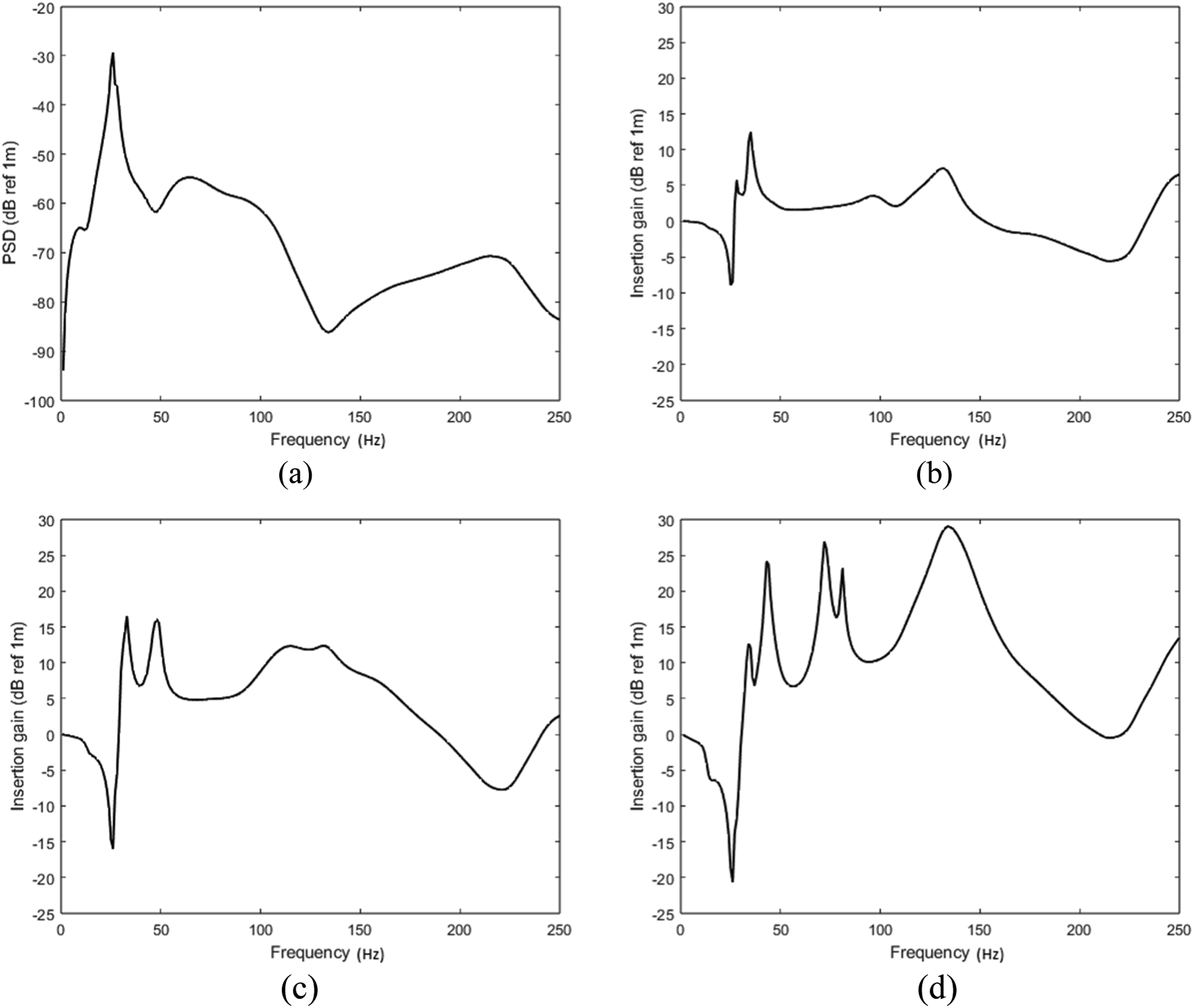
Effect of local resonators on ground-borne vibration mitigation
The effect of the local resonators on vibration mitigation has been explored via parametric analysis that shows the impact of the added resonator’s natural frequency and resonator’s mass on ground-borne vibration mitigation. The displacement at free-surface has been plotted against the frequency above the train for tracks with different resonator’s natural frequencies 30 Hz, 50 Hz, 70 Hz and 90 Hz in Figures 12–15 in sequence, and for three resonator’s masses 12 kg, 18 kg and 24 kg, the local resonator damping coefficient (a) Power spectral density for the displacement at the free-surface plotted against the frequency above the train for regular track. (b), (c) and (d) Insertion gain for track with local resonators having natural frequency fr 30 Hz and resonator’s mass equals 12, 18 and 24 kg in sequence. (a) Power spectral density for the displacement at the free-surface plotted against the frequency above the train for regular track. (b), (c) and (d) Insertion gain for track with local resonators having natural frequency fr 50 Hz and resonator’s mass equals 12, 18 and 24 kg in sequence. (a) Power spectral density for the displacement at the free-surface plotted against the frequency above the train for regular track. (b), (c) and (d) Insertion gain for track with local resonators having natural frequency fr 70 Hz and resonator’s mass equals 12, 18 and 24 kg in sequence. (a) Power spectral density for the displacement at the free-surface plotted against the frequency above the train for regular track. (b), (c) and (d) Insertion gain for track with local resonators having natural frequency fr 90 Hz and resonator’s mass equals 12, 18 and 24 kg in sequence.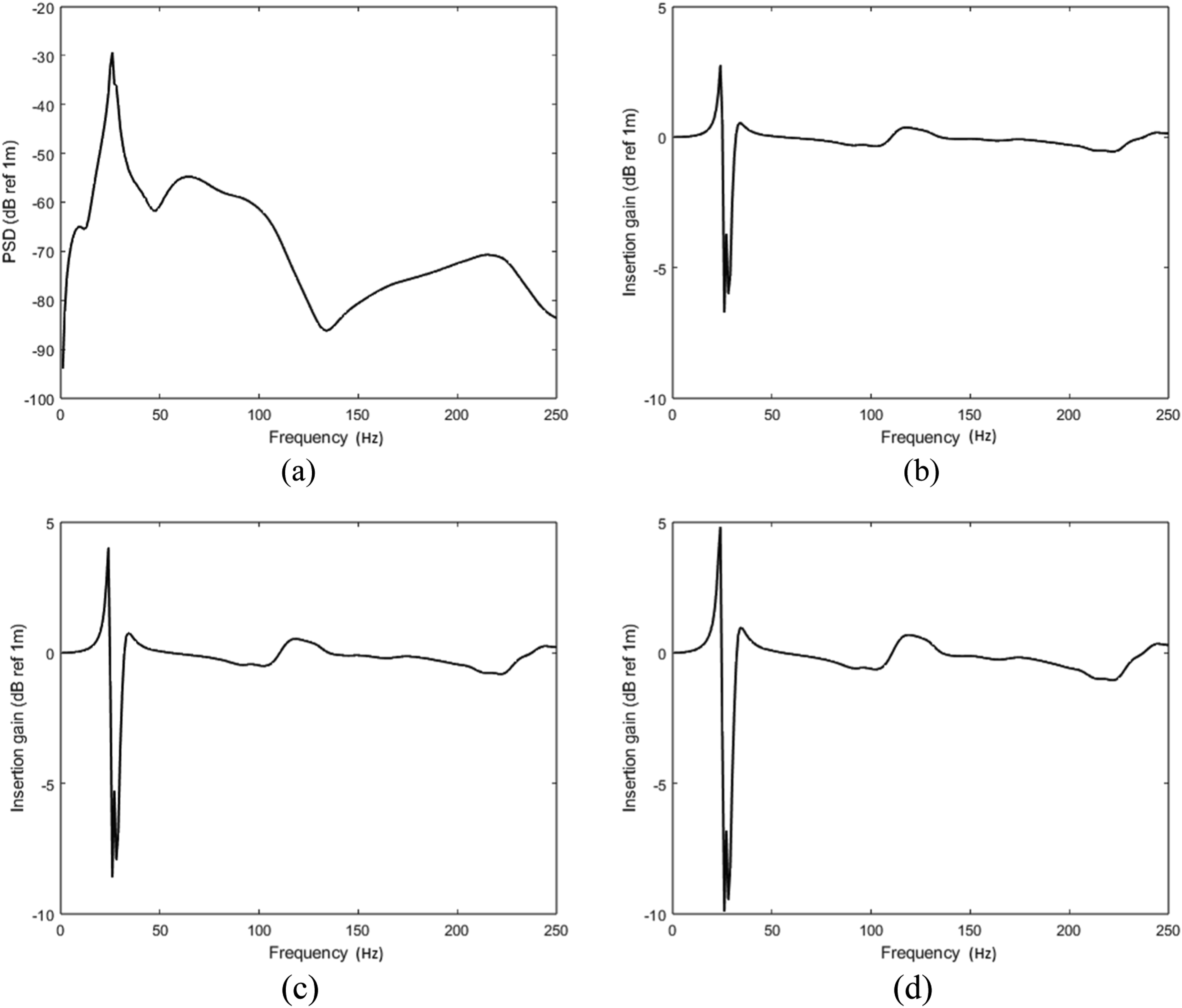
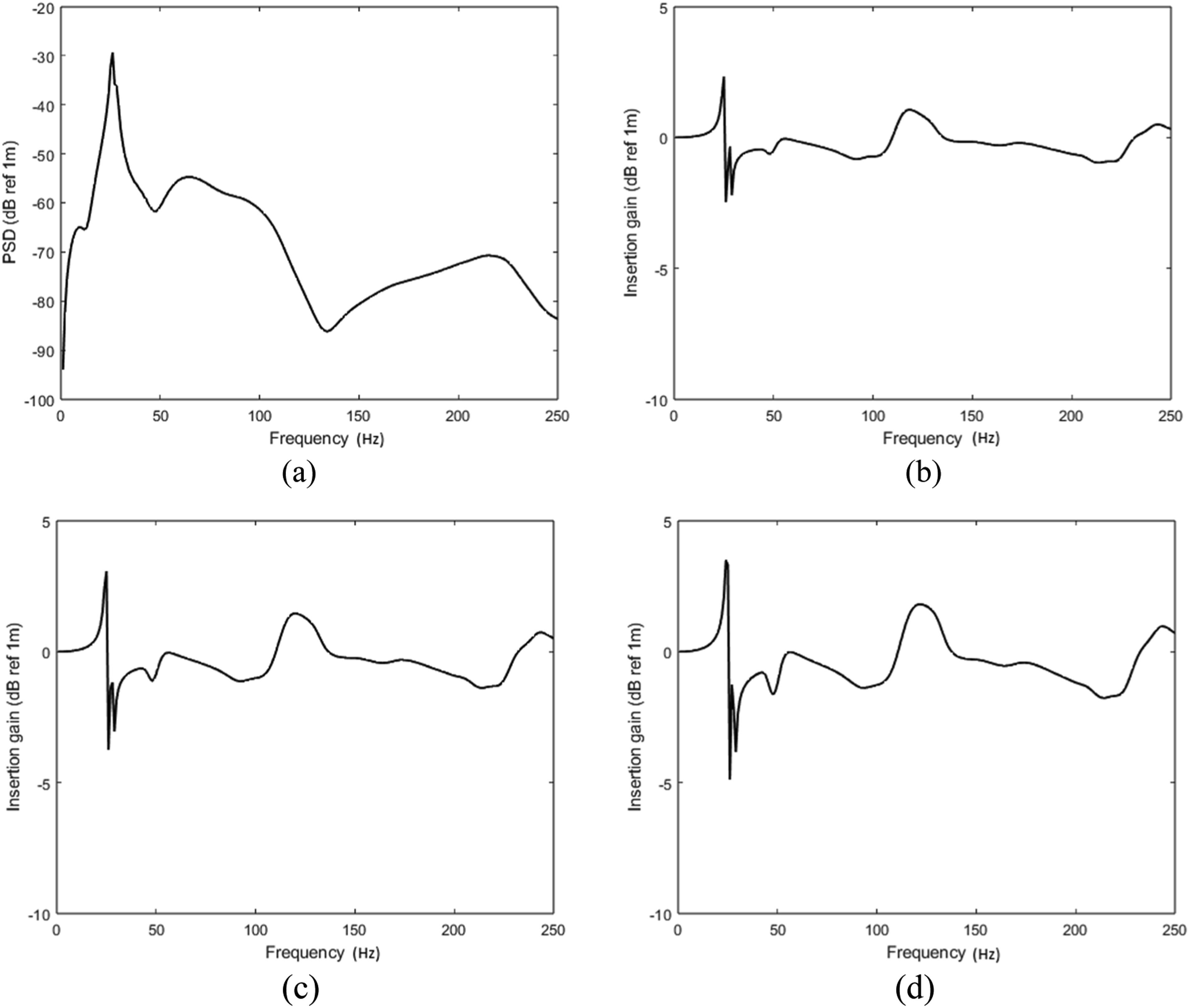
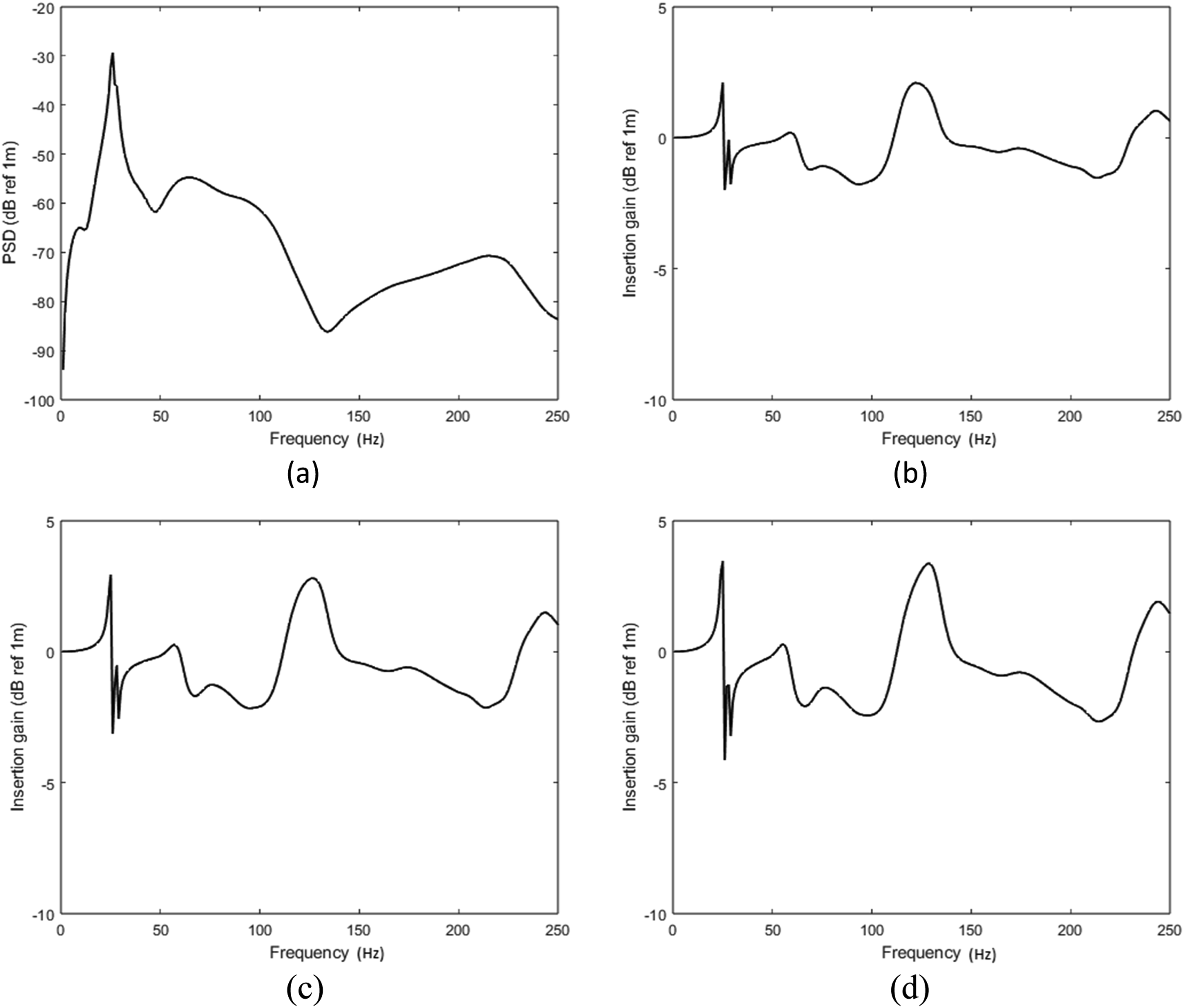
Taking into account the true levels of ground-borne vibrations which transfer, propagate and reach the free surface, more attention should be payed to the low frequencies. Hence, it is clear that the largest amplitude of mitigation (10 dB ref 1m) in the considered frequency range happened when the biggest resonator’s mass added at the lowest resonator’s natural frequency, that is, 30 Hz see Figure 12(d). Although, applying the resonators would reduce the ground-borne vibration for wider frequency ranges with the rise in resonator’s natural frequencies, the level of mitigation will decrease with the rise of resonator’s natural frequencies. Hence, choosing the suitable resonator’s parameters depends on the compromising between the considered frequency range and the level of mitigation wanted. However, applying the resonators would reduce the ground-borne vibration at a low-frequency range of 25–200 Hz by around 4 dB ref 1m see Figure 15(d) as an example.
To explain the importance of targeting low frequencies when introducing countermeasures for ground-borne vibration, the level of vibration from a real roughness is shown in Figure 16 which shows the dynamic excitation after being weighted with a real roughness using randomly-generated unevenness from standard PSD using the formula shown in equation (28) which has been used by previous researchers37,38 and others. Weighted Power spectral density for the real displacement at the free-surface plotted against the frequency above the train for medium track condition.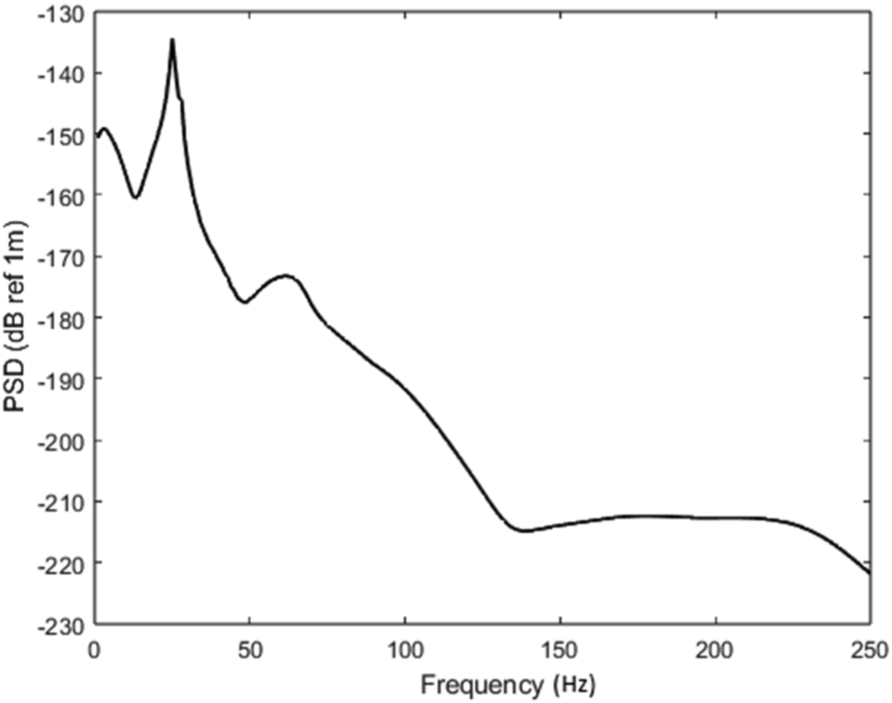

Figure 17 shows the weighting factors for three different track conditions poor, medium and good. Weighting factor plotted against the frequency for three different track conditions: ___: poor condition track, …: medium condition track and .-.-: good condition track.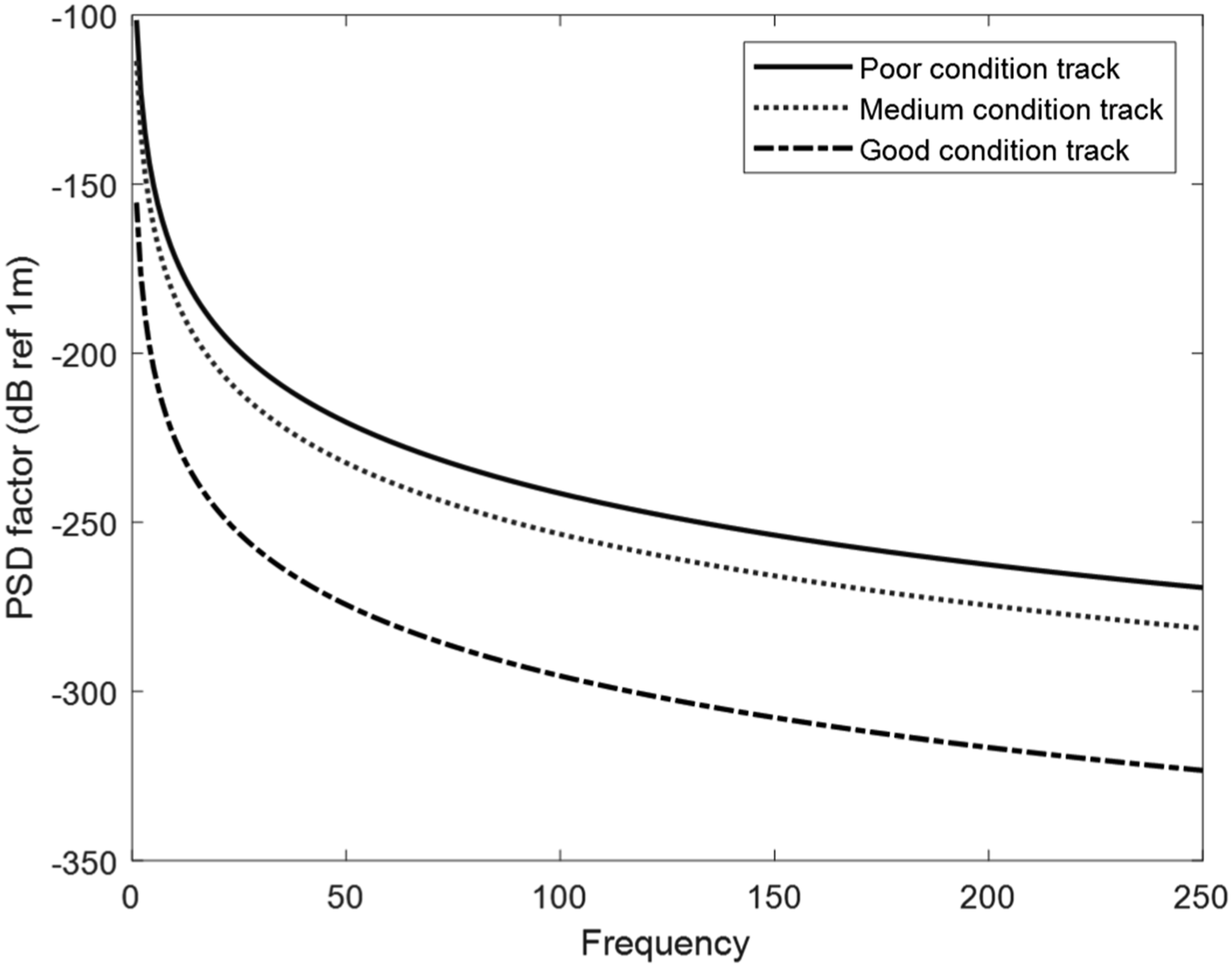
The weighting factor tends to decrease with the increase of the frequency and that is what makes the higher frequencies less significant when multiplying this factor with the PSD for a roughness excitation of a unit value (i.e. white noise) as illustrated in Figure 17. Generally speaking, the amplitude of the ground-borne vibration that transfer and reach the surface in low frequencies are more significant than those in higher frequencies. Hence, the focus on this work is on low frequencies.
Conclusion
The responses in the free surface from a train with three vehicles running on underground railway track at a constant speed were calculated using two different models. The first approach is based on modelling the track as discontinuously supported beam and the second approach is based on modelling the track as continuously supported beam, it is assumed that for both models, each axle gets excited by the same relative roughness a part from a time lag using pull-through model. The two models gives the same results for the dynamic displacement at free-surface, Hence, the discontinuous support model is verified.
The effect of two different types of in-track countermeasures are investigated in this paper, these are rotational stiffness introduced with the usual vertical stiffness and a different simple local resonator. The Power Spectral Density is calculated for both and compared with the regular track through calculating the insertion gains. However, the results show for the parameters considered that using the rotation restrained support can effectively reduce the ground-borne vibration levels by up to 20 dB for low frequencies, taking into account that mitigation level of this countermeasure tends to increases with the increase in the rotational stiffness for low frequencies. Furthermore, the use of local resonators would reduce the ground-borne vibration by 4–10 dB for frequencies in the range 20–200 Hz, depends on the compromising between the considered frequency range and the level of mitigation wanted, such that applying the resonators would reduce the ground-borne vibration for wider frequency ranges with the rise in resonator’s natural frequencies, while the level of mitigation will decrease. Also it has been noticed that increasing the resonator’s masses would decreases the ground-borne vibration at low frequencies.
Footnotes
Acknowledgements
The authors would like to acknowledge funding from Qatar Rail through grant number QUEX-CENG-QR-21/22-1.
Declaration of conflicting interests
The author(s) declared no potential conflicts of interest with respect to the research, authorship, and/or publication of this article.
Funding
The author(s) disclosed receipt of the following financial support for the research, authorship, and/or publication of this article: Qatar Rail through grant number QUEX-CENG-QR-21/22-1 and Open Access funding provided by the Qatar National Library.