
Abstract
The joint construction of subways and other public buildings is a relatively newer type of construction. There is little research experience in the vibration characteristics and track damping design for this type of structure. In this study, a field test was adopted to conduct site measurement analysis on the vibration response of the joint construction project consisting of a subway tunnel and a building with typical frame structures. Numerical simulation methods were also adopted to, respectively, assume the use of ordinary tracks and steel-spring floating slab tracks for the subway for the situation where the Cologne-egg high-elastic fasteners were used on the track for damping purposes. Comparisons were performed to analyze the difference in the system vibration response between three different types of track. The results showed that the high-elastic fastener track and floating slab track both have a certain degree of damping effect compared with an ordinary track. Specifically speaking, the former has a damping advantage for frequency bands below 20 Hz, while the latter has the advantage for frequency bands above 20 Hz under the impact of the structural vibration characteristics for this joint construction. For this jointly construction structure, affected by the natural vibration characteristics of the structure, the natural frequency of the floating slab track is within 4 ∼ 10 Hz, and the similar vibration reduction effect can be achieved. This indicates that the structural vibration characteristic of the jointly constructed structure is an important factor determining the appropriate natural frequency of the floating slab track.
Keywords
Introduction
Because of the scarcity of urban soil resources, a new type of structure jointly constructed of a subway and other public buildings has come into being in recent years in order to ease the contradiction between the land use for urban subways and other buildings. The joint construction is presented as the subway and the public building sharing a portion of the overall structure. The roof of the underground subway station serves as the bottom floor of the building above for many joint construction subway and high-rise buildings. In the joint construction project, part of the vibration excitation produced by the running subway trains spreads directly from the track bed, frame columns, and floors to the building structure that is above railway lines. Without a standard soil layer attenuation found in typical construction, the jointly constructed subway and public building results in structural vibration. Compared with the environmental vibration produced by the situations where the subway is built separately from other public buildings, the structural vibration is much more severe in the condition of joint construction.
A large number of studies have been carried out on the aspects such as track damping and the vibration of adjacent buildings caused by subway operations. For example, field testing,1–10 numerical simulations,11–13 theoretical calculation, 14 and empirical formula 15 were primarily used for the analysis and forecasting of environmental vibrations caused by the subway operation. Floating slab track, trapezoidal sleepers, elastic support block ballastless track and damping fasteners have been proposed to provide vibration damping of the ballastless track. Additionally, damping fasteners, sleeper mats and under-the-ballast rubber mats have been proposed as well for vibration damping of the ballasted track. Nevertheless, there are very few studies concerning the vibration response of this structural system owing to the limited number of cases where the subway was jointly constructed with the building above. The existing studies include Shunhua Zhou et al. 16 which employed a numerical simulation method to study the effect of the tunnel substrate stiffness on system vibration when a museum was constructed jointly with the rail transit tunnel. Guiyuan Xiao et al. 17 used field testing to study the environmental vibration propagation and frequency distribution characteristic of a structure jointly constructed by the subway and a train station. Hou et al. 18 used a coupled vehicle-track-building model for analyzing the situation where the subway line runs directly above the first floor of the main building, to predict the vibration levels in the structure. However, no comparative analysis has been developed regarding track damping measures and their effect on jointly constructed subway tunnels and high-rise buildings structures.
The differences in structure and stiffness of dissimilar joint constructions lead to natural vibration of diverse structures, which is related to the damping effect of the track structure. In order to accumulate more data and experience into the research of vibration of a joint construction system and the track damping design, this paper used the joint construction of a subway station in Shanghai and its upper typical frame construction as a case study. The research was performed by conducting field tests and numerical simulations comparing the impact of ordinary track, Cologne-egg high-elastic fastener track and steel-spring floating slab track with regards to the vibration response of the joint structure in order to provide a basis of parameters for a track damping design.
Joint construction overview and vibration tests
One jointly constructed structure that has already been put into use consists of an underground subway station with an office building above it. The underground two-level structure holds the station platform and station hall where the seven levels above the ground are the concrete frame structure for the office building. Each type of cross-section is similar for the overall structure. Figure 1 is a sectional view of the joint construction. Inside the subway station, the Cologne-egg high-elastic fastener was used for track damping. No train crossing will occur in this subway station, and the average speed of the train arriving and departing the station will not exceed 30 km/h. Sectional view of the joint construction.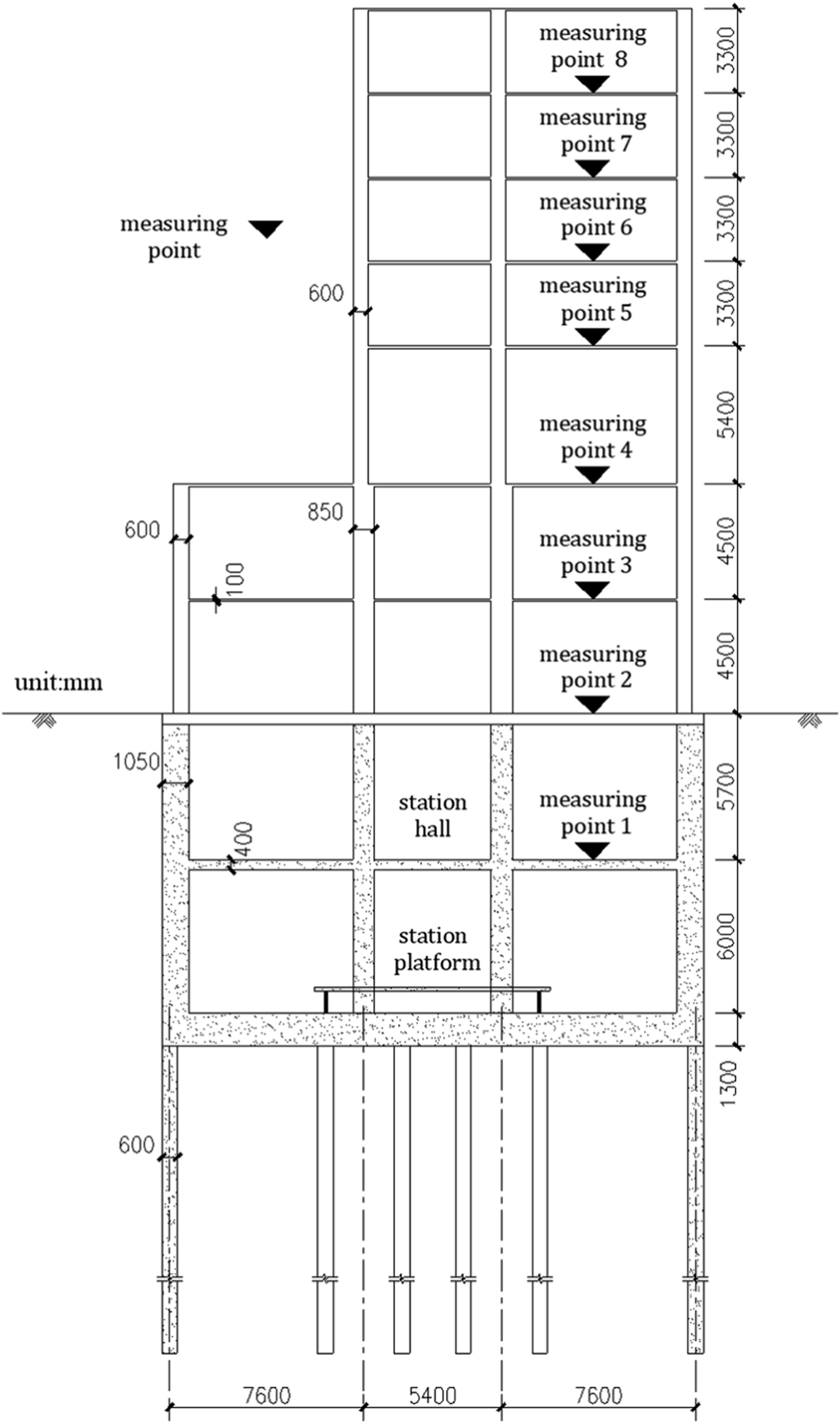
Instruments used in the field vibration test include: a PCI (6024E data acquisition card) produced by National Instruments Corporation (NI) with 12-bit resolution and a maximum single-channel sampling frequency of 200 kHz, an 891 amplifier, and an 891-II vibration pick-up developed by the Institute of Engineering Mechanics, China Earthquake Administration. Vertical acceleration sensors were laid out from the floor of the subway station hall to each floor of the building given that the vibration induced by the subway was mainly vertical. Additionally, the vibration acceleration signals were collected for each floor for both cases of the trains passing and no trains. The arrangement of the measuring points is shown in Figure 1.
When testing, the total time spent on each floor for collecting vibration data was approximately 30 minutes, which was equivalent to the time for five trains to arrive and depart the station. The group with the highest vibration peak was selected for the analysis. The vibration acceleration data caused solely by subway operations can be obtained by stripping off the vibration acceleration curves of the measuring points from the background.
19
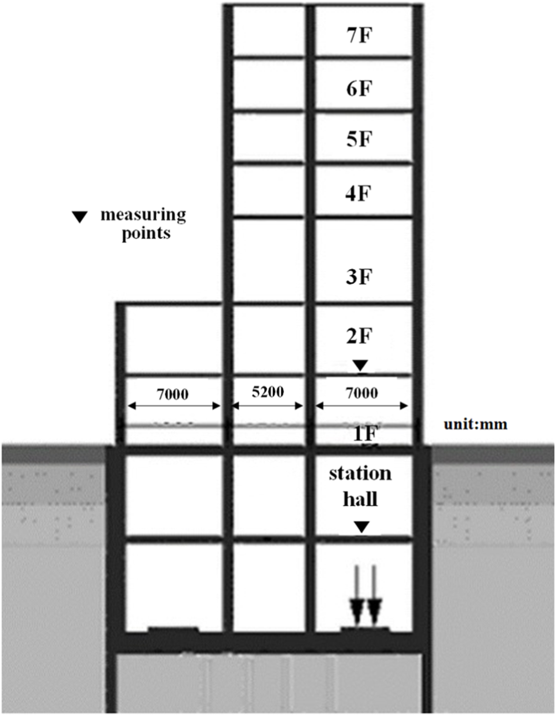
Figure 2 shows the typical vibration acceleration curves of different measuring points. Typical vibration acceleration time history curves of different measuring points. (a) Platform level, (b) Station hall, (c) The second floor, (d) The seventh floor.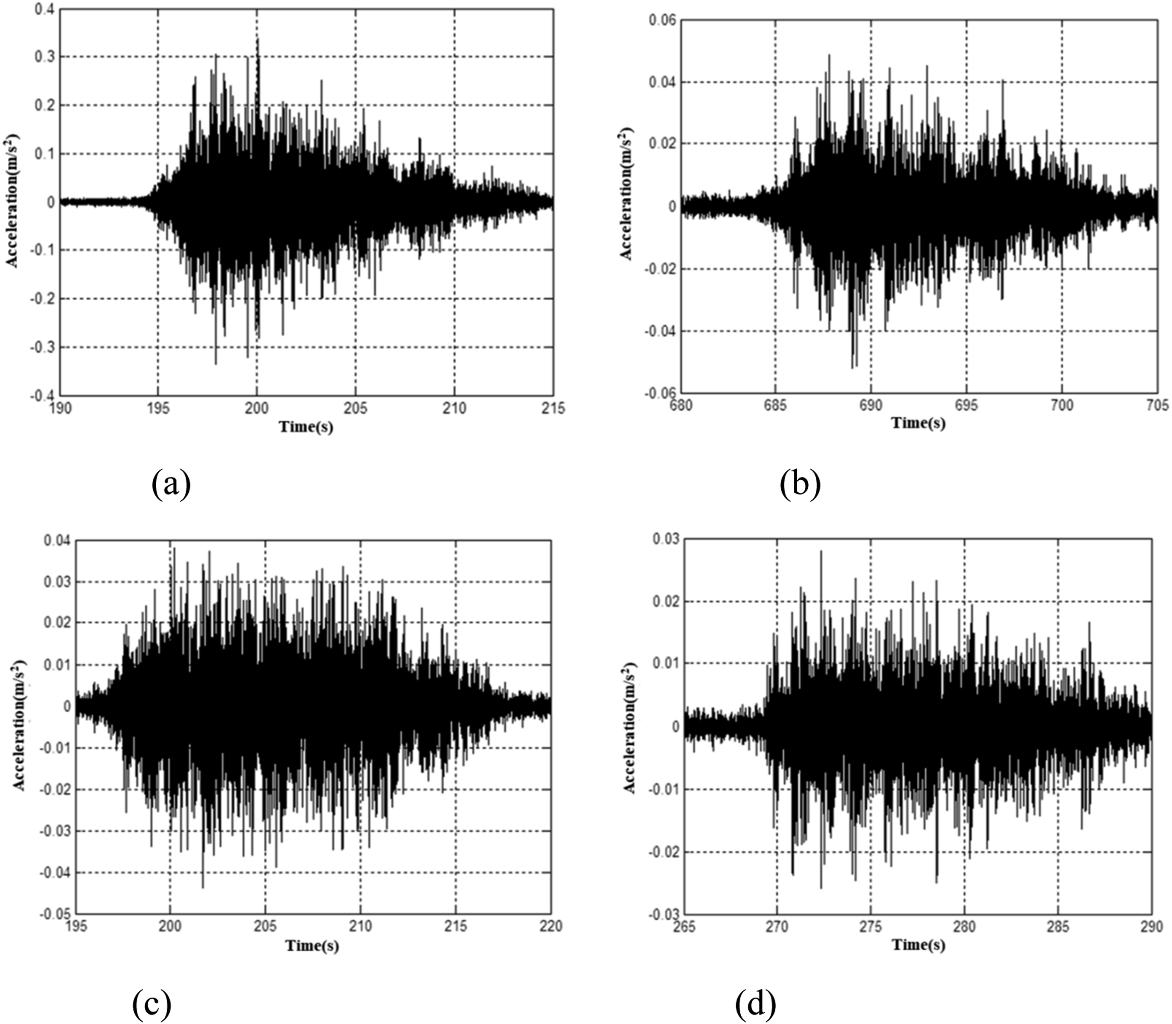
It can be seen from the test results of all measuring points that when the train was loaded, the duration of the vibration acceleration waveform at each measuring point ranges from 10 s to 15 s. However, the platform that had larger acceleration amplitude (up to 0.33 m/s2), while the acceleration amplitude of all other levels exhibited little variation. For example, the station hall had a maximum amplitude value of 0.053 m/s2, the second floor had a maximum amplitude value of 0.042 m/s2, and the seventh floor had a maximum amplitude value of 0.028 m/s2.
As can be seen from the frequency domain results of the vibration acceleration in Figure 3, the vibration acceleration signal of each measuring point exhibited significant characteristics of medium-high frequency. The dominant frequency of the platform was distributed within the 100–160 Hz range and peaked at 117.5 Hz. The dominant frequency for other levels was mainly distributed within the 30–80 Hz range and peaks at approximately 35–40 Hz. The frequency spectrum curve of vertical vibration acceleration for each measuring point. (a) Platform level, (b) Station hall, (c) The second floor, (d) The seventh floor.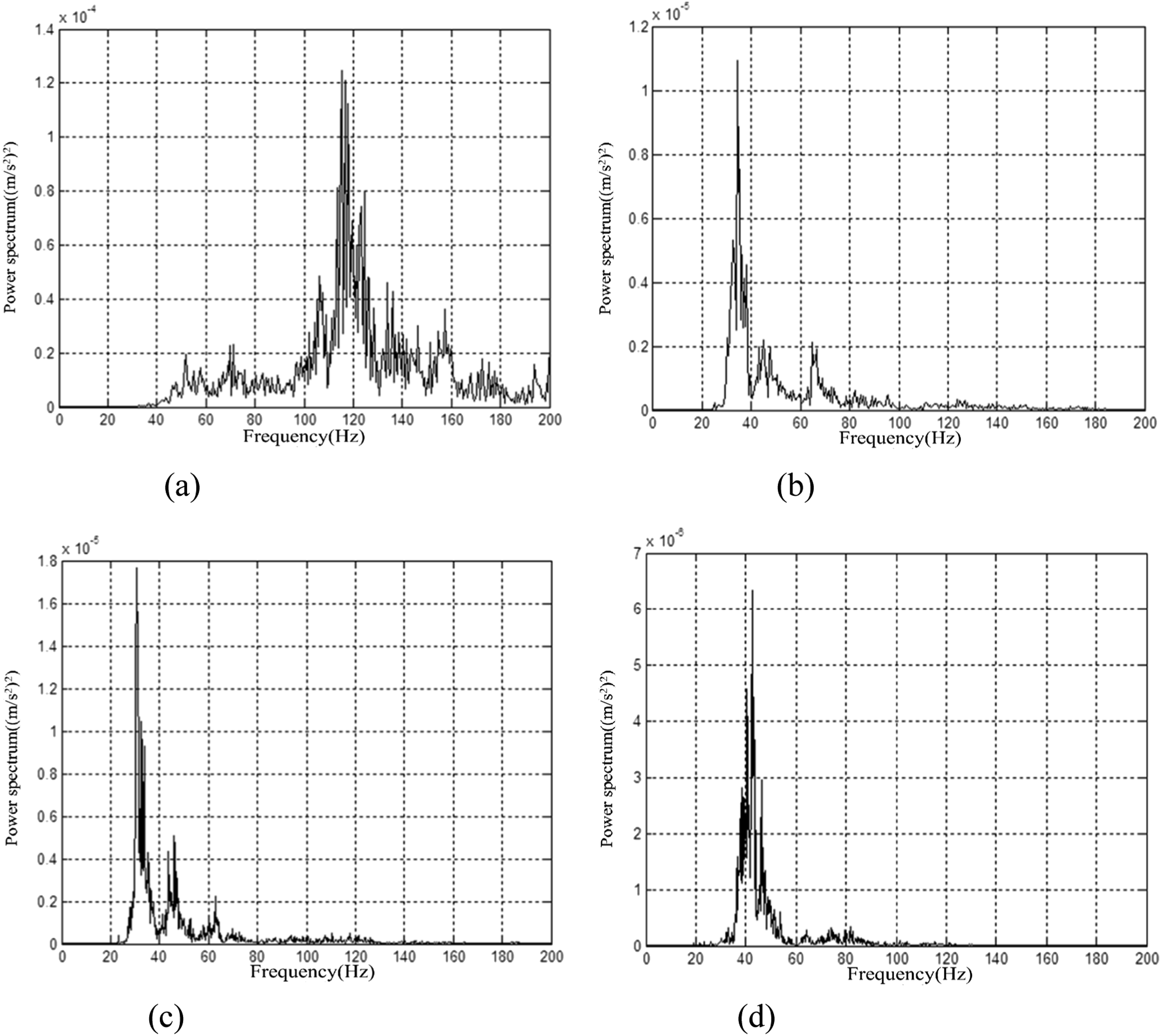
In addition, the analysis concerning the 1/3-octave vibration-level curve of each measuring point can be seen in the subsequent paragraphs of this paper.
Numerical simulation analysis of impact from track types and parameters on the vibration response of joint construction
By comparing the impact of common track types and parameters on the vibration response of joint constructions, the vibration characteristics of joint construction structures can be clearly recognized and understood. Subsequently experience can be gained in the optimization of track damping designs for similar projects in the future. For hypothetical cases, the subway station used both an ordinary track and a steel-spring floating slab track designs. Through numerical simulation, the vibration response of joint construction was analyzed and compared with data from the actual test based on the high-elastic fastener track. In the numerical calculation, the track bed surface was regarded as the boundary surface. The downward excitation force from the interaction between the track and the subway trains on the track bed was obtained through field testing or from the vehicle-track coupling dynamic model. This excitation force was then used as the input for the dynamic simulation analysis on the track bed joint construction (including the tunnel structure and ground construction). Additionally, the excitation force was used in the foundation coupling model to obtain the vibration response of the structural system pattern. Considering the regularity characteristics of the structure, and in order to save computing time, the coupling model of the track bed joint construction foundation was assumed to be a plane strain model. Research experience 20 shows that this simplifying approach can reach a conclusion relatively consistent with reality.
Equivalent load spectrum of the track bed surface for different track types
Ordinary track
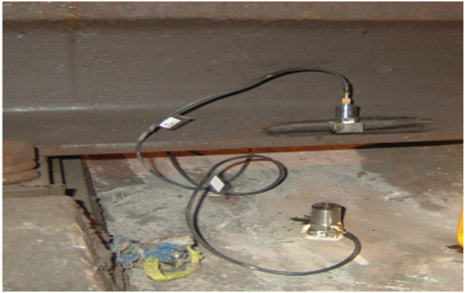
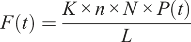
After equivalent treatment, the vertical impact force on the measured wheel-rail of ordinary steel track can be used as the input load of the track bed joint construction and foundation of a 2D dynamic finite element model. Figure 4 shows the wheel and rail impact of an ordinary steel track obtained using the rail web method (Figure 5) based on conditions similar to the driving conditions for this case (speed and track irregularity, etc.). When calculating the planar problem, the dynamic load was assumed to be divided by the track and sleepers, and converted into line load distributed evenly along the longitudinal centerline of steel track. The load was calculated by the following formula Measured wheel-rail force. The rail web method.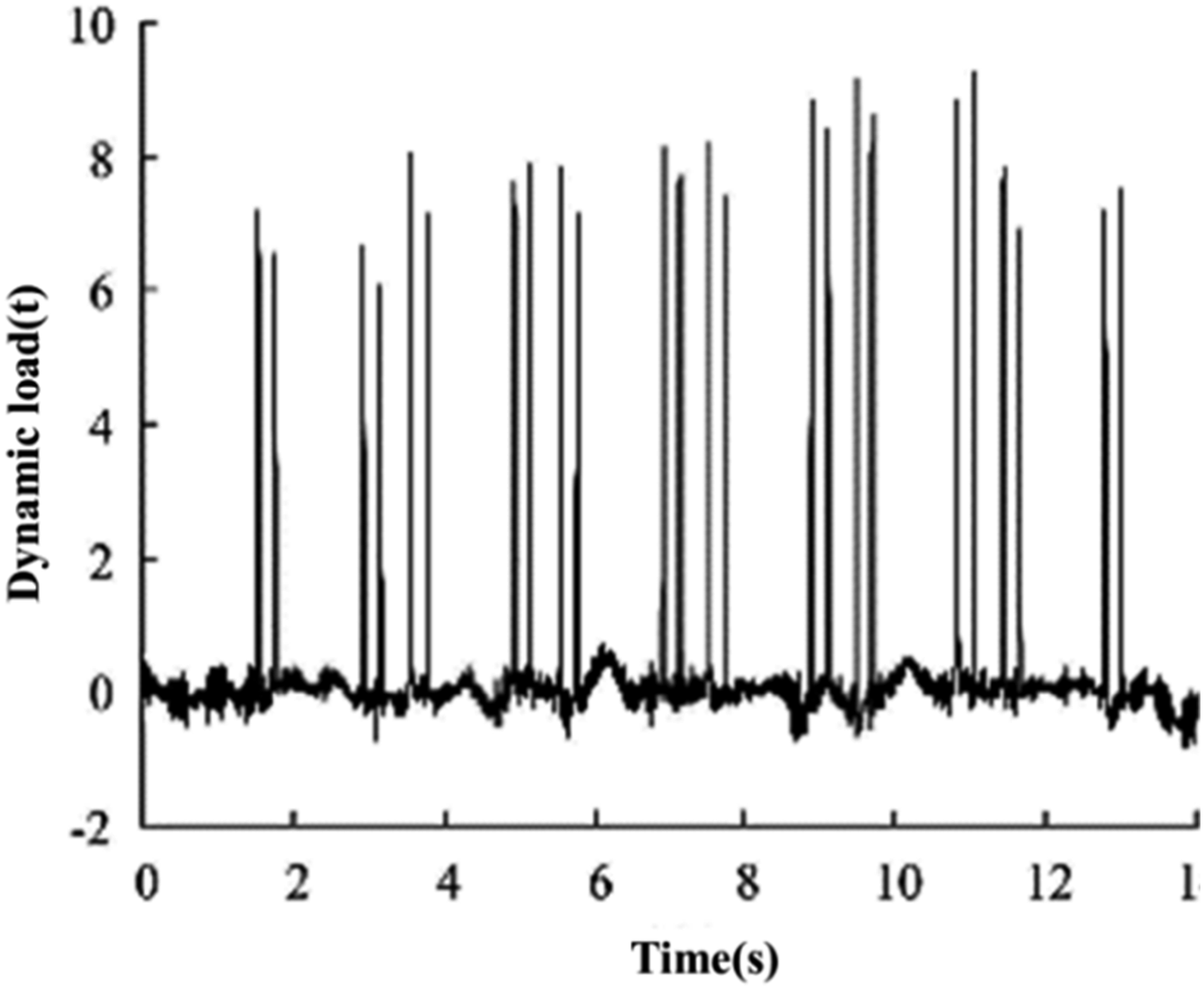
Steel-spring floating slab track
The theory of vehicle-track coupling dynamics 22 was used to treat the train, track, and floating slab as a vibration system coupled with each other. Additionally, the theory was used to establish a vibration analysis model of a subway train and floating slab track coupling to calculate the force of the steel spring pivot point under the floating slab track. After equivalent treatment, this force was input into the 2D dynamic finite element model developed for the track bed joint construction and foundation, in order to obtain the vibration response of the joint construction caused by subway operations.
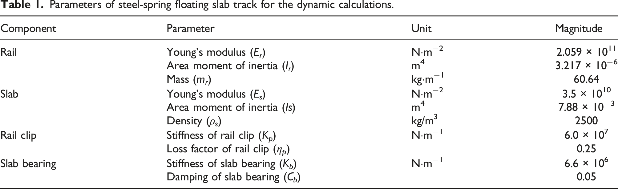
The train-steel spring floating slab track coupling dynamic model is established. The subway train model used in this study was the type A subway train under effective operation (Figure 6). The track irregularity was based on the American five-level spectrum (i.e., wavelength range of 0.1 m to 30 m) with an average speed of 30 km/h. The steel-spring floating slab track consisted of a reinforced concrete floating slab, elastic supports, a concrete base, and supporting fasteners as shown in Figure 7. For this calculation model, a single floating slab was 25 m in length with two rows of 21 steel springs side by side with varied spacing of 1.8 m and 1.2 m. The natural frequency of the floating slab was changed by altering its thickness. The parameters of the floating slab track used for the dynamic calculations are shown in Table 1. Schematic of subway train and steel-spring floating slab track. Subway train—steel spring floating slab track coupling dynamic model. Parameters of steel-spring floating slab track for the dynamic calculations.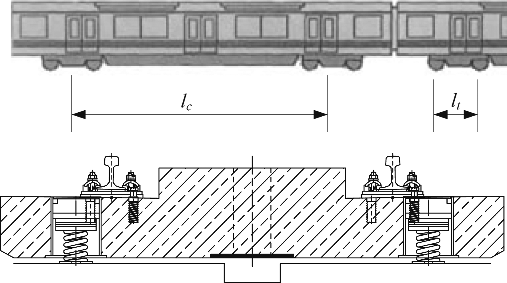
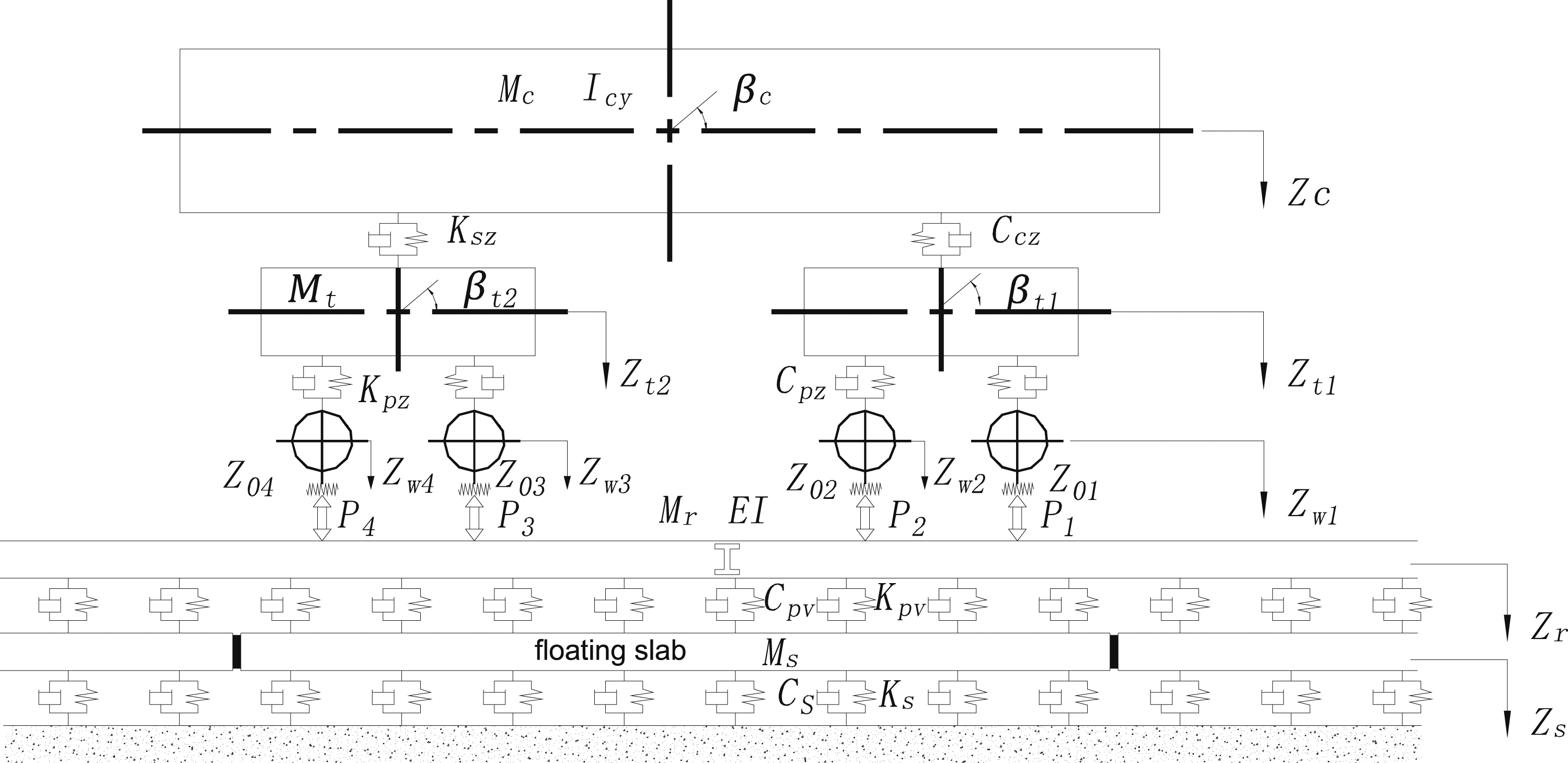
The steel-spring floating slab track coupled dynamic model was established as shown in Figure 7. The support reaction force time-history curve of the single steel-spring floating slab track was, respectively, calculated for the natural frequencies of 4 Hz, 6 Hz, 8 Hz, and 9 Hz, as shown in Figure 8. Support reaction force-time curve of single steel-spring floating slab track.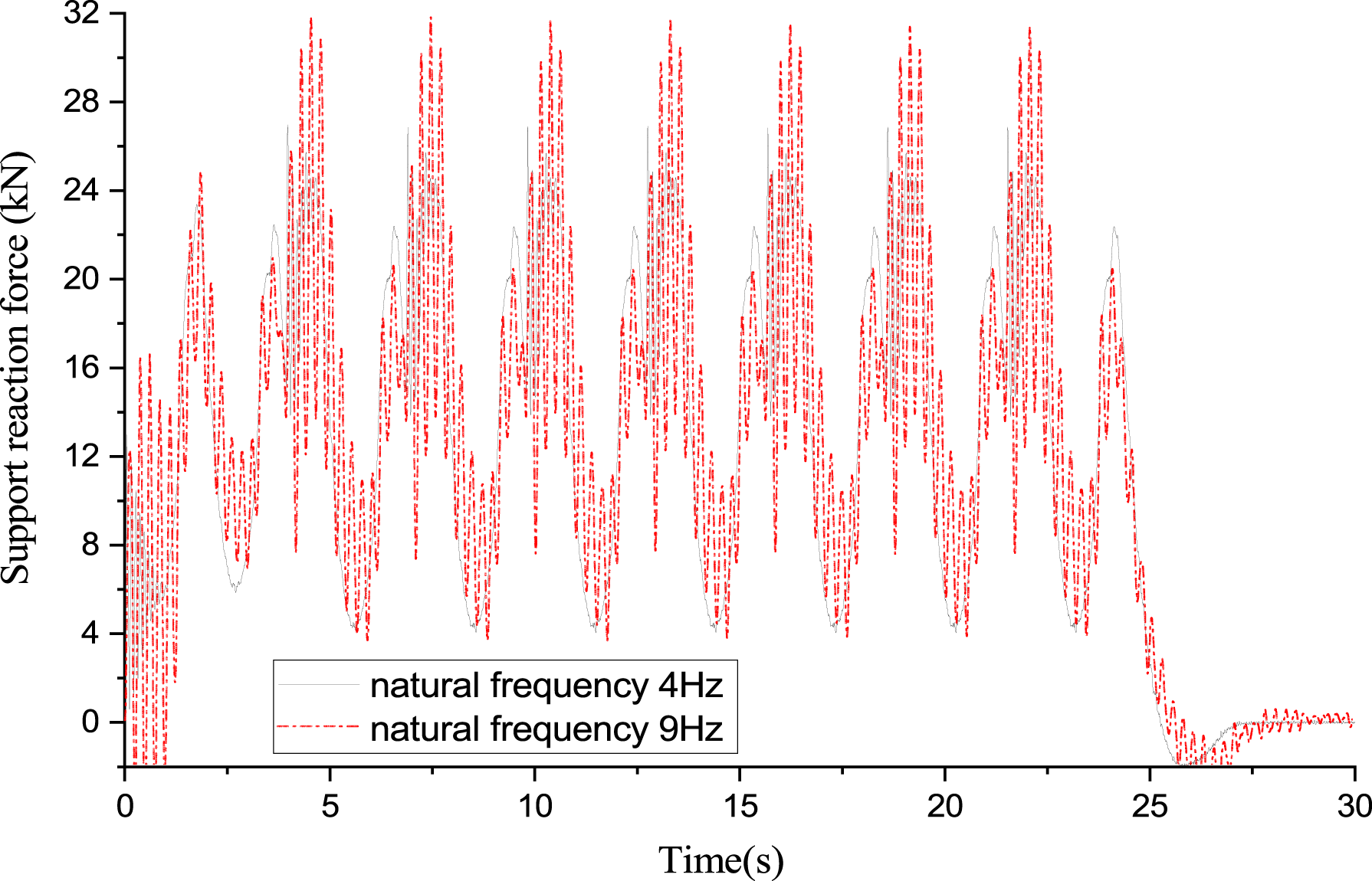
It can be concluded from the Figure 8 that the support reaction force of the steel spring under the floating slab was a series of an excitation load spectrum with a phase difference. In a 3D calculation model, a series of point loads could be input as the load excitation. However, for a 2D model, the proper equivalent treatment was needed to obtain the load excitation of the model. Therefore, this study conducted several numerical experiments.
Figure 9 is based on the steel spring, floating slab schematic diagram shown in Figure 6. A 3D numerical model (including two floating slabs) was established. The support reaction force distribution of the steel spring under the static load of a single wheel weight, the bogie wheel weight, and two side-by-side bogie wheel weights were compared and analyzed. As can be seen from the figure, when there was a centralized force on the track, about 16 steel springs under the floating slab bore the force. When the load was carried by one or two adjacent bogies, approximately 24 and 26 steel springs bore the force. On this basis, even if a plurality of bogies of adjacent trains were added, the support reaction force of 26 steel springs under a load of two adjacent bogies would not change significantly. Steel spring load sharing distribution.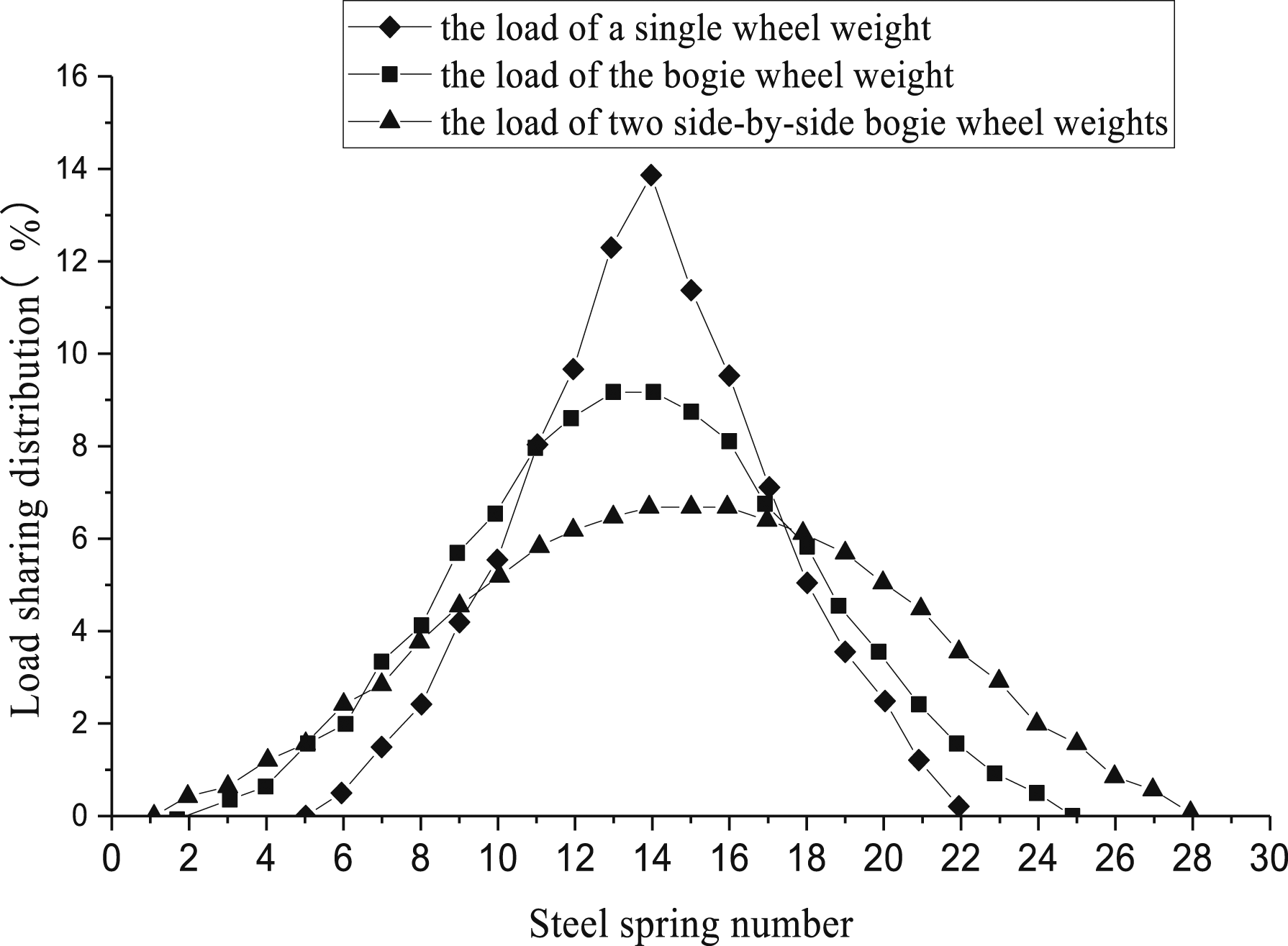
Through the simulation calculations and test comparison verification of the steel spring, floating slab ground section, a reasonable approach for inputting the equivalent load of a steel spring in a 2D model can be obtained. Figure 10 shows the comparison between the calculations from the 1/3-octave band vibration level of a specific observation point on the ground and actual measurements using a different equivalent method under the condition that the natural frequency of the floating slab was 8 Hz. The calculations are based on the support reaction force of any spring, the average of the support reaction force for 21 springs under the same side of the slab along the length, and the average of the support reaction force of 84 springs under the same side of four slabs along the length. The figure shows that it was reasonable to increase the entire spring reaction force spectrum of the 21 steel springs under the same side of a single floating slab. Then take the average along the length range as an external excitation spectrum of the steel spring in a 2D model. Comparison of the steel spring, floating slab ground section measurement with 1/3-octave band vibration level calculation.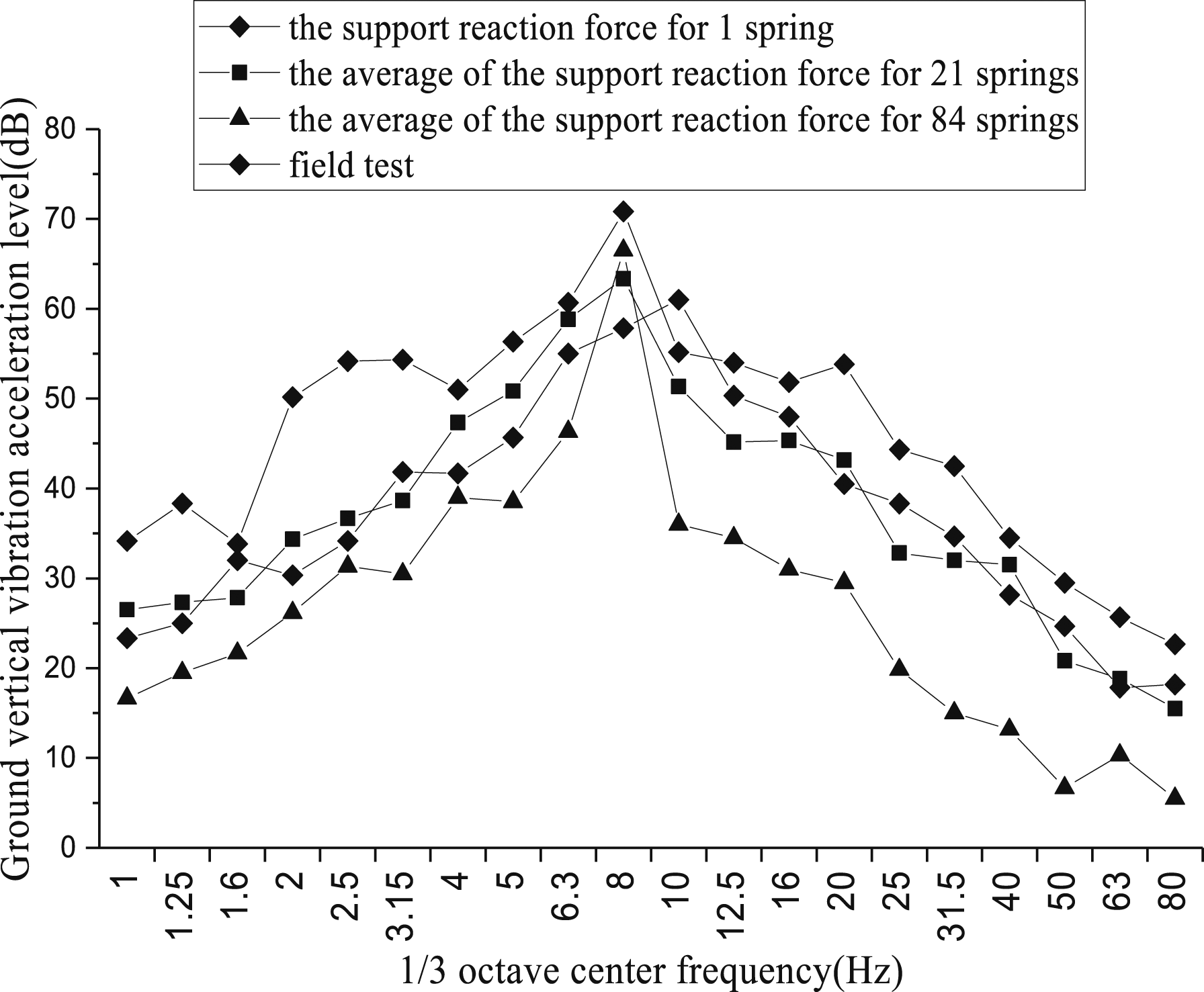
Track bed-joint construction foundation 2D dynamic finite element model
The calculation parameters of the dynamic finite element model.
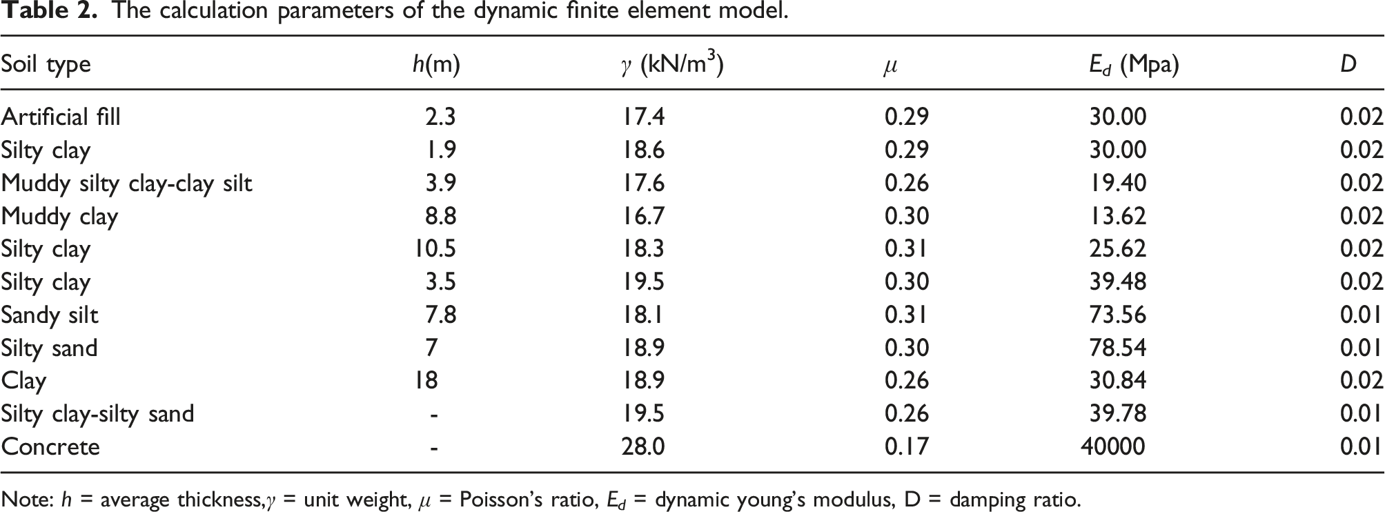
Note: h = average thickness,γ = unit weight, μ = Poisson’s ratio, E d = dynamic young’s modulus, D = damping ratio.
The local finite element model.
Numerical simulation results and analysis
Comparative analysis of the time-domain calculations
Only the calculation results from the measuring points for the second floor were selected for the analysis owing to the simulation in calculation regularities reflected by each measuring point when using the same type of track. The calculation results were then compared with the measured data when using the high-elastic fasteners. Figures 12 and 13 show the vibration acceleration curves of the measuring point when adopting the ordinary track and floating slab track, respectively. Time-domain spectrum of vertical vibration acceleration when using ordinary track on the second floor of the building. Time-domain spectrum of vertical vibration acceleration when using floating slab track with natural frequency of 6 Hz on the second floor of the building.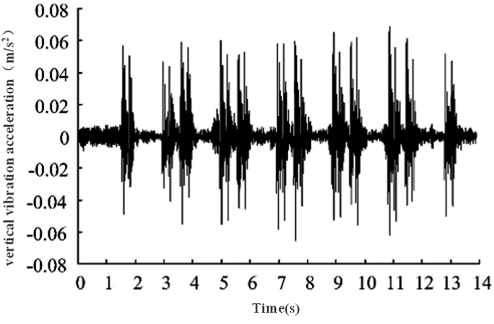
As can be seen from the Figures 12 and 13, the peak vibration acceleration on the ordinary track was about twice as high as that when using the high-elastic fastener for the same measuring point and approximately ten times the peak when using a floating slab track with a natural frequency of 6 Hz. This shows the steel-spring floating slab track has the best damping effect. However, when using the steel-spring floating slab track, the vibration of each measuring point lasts the longest when a single train passes. The vibration duration of each measuring point was basically the same when an ordinary track or high-elastic fastener track are used.
Comparative analysis of the 1/3-octave band vibration level
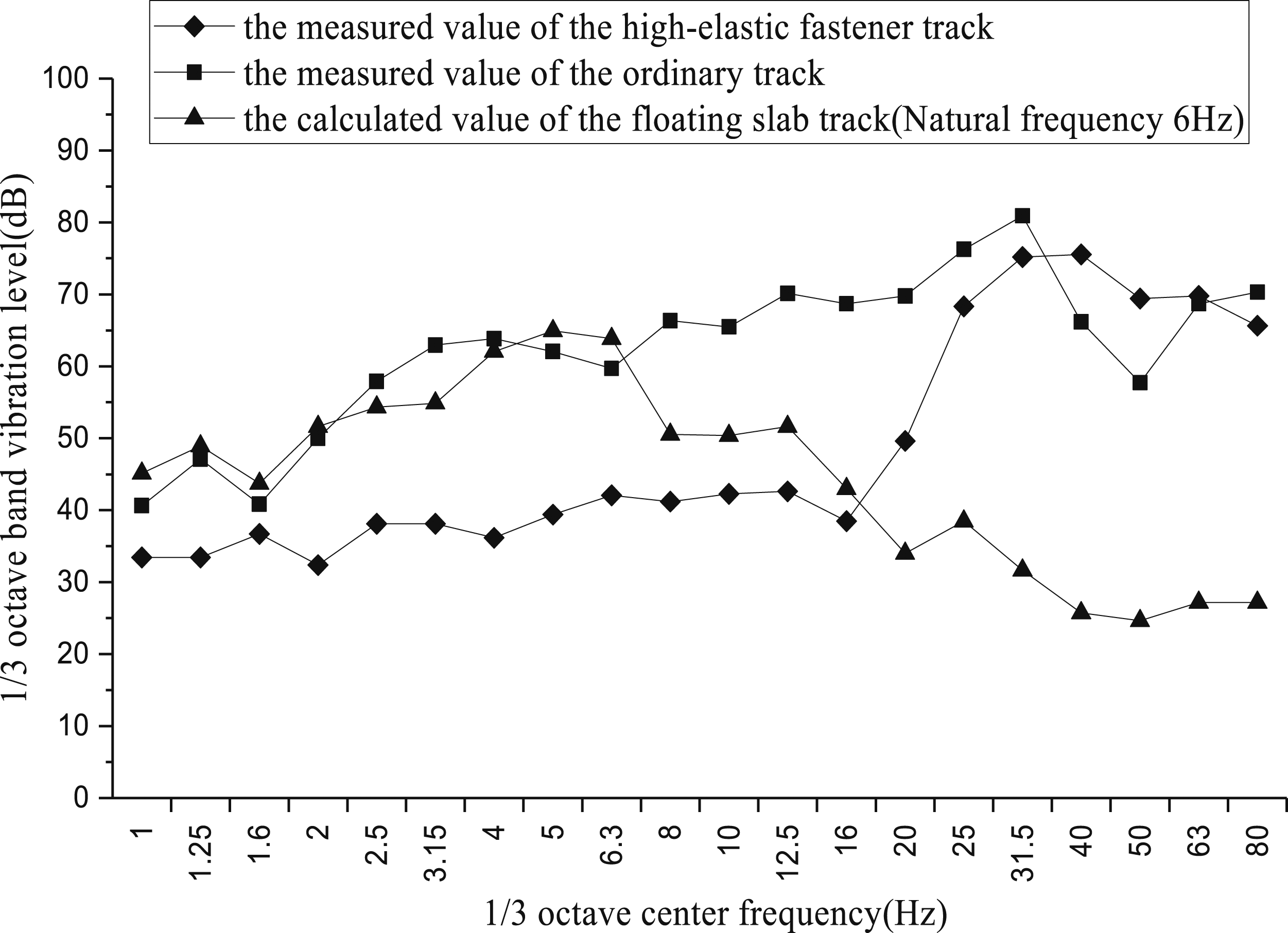
Figure 14 shows the comparison curves of the 1/3-octave band vibration level of the same measuring point when using an ordinary track, a floating slab track and a high-elastic fastener track. As can be seen: a) When compared with the ordinary track, the high-elastic fastener track has relatively significant damping effect for vibrations within the frequency band of 0–20 Hz, with a maximum frequency division vibration level reduction of 20 dB (occurring at the center frequency of 10 Hz). However, the difference of the maximum vibration level of the 1/3-octave band between the two was only around 5 dB. b) Compared with an ordinary track, the floating slab track has significant damping effect on vertical vibrations greater than 6 Hz or more. The maximum vibration level of the 1/3-octave can be reduced by about 15 dB. Additionally, not only does the divided vibration level decrease by 30 dB or more (at the center frequency of 40 Hz), but the vibration energy near the natural frequency can easily increase. c) 20 Hz was approximately the cut-off point for the vibration bands, above the cut-off point indicating the floating slab track behaves better than the high-elastic fastener track, while below the cut-off point it was the contrary. However, the 1/3-octave maximum vibration level of the floating slab track was approximately 10 dB lower than the high-elastic fastener track. Comparison between the measured values of Cologne-egg high-elastic fastener track and the 1/3-octave band vibration level calculations of the ordinary track and floating slab track.
Impact from the natural frequency of steel-spring floating slab track on the vibration response of joint structure
Figure 15 compares the damping effect of the steel-spring floating slab track of different natural frequencies in the joint construction. As can be seen from the figure, as the natural frequency of the floating slab increases for the same measuring point, the 1/3-octave band maximum vibration level of the vibration response of the measuring point was reduced. However, for steel-spring floating slabs of different natural frequencies (i.e., 4–10 Hz), the maximum difference between the vibration levels of the measuring points does not exceed 30 dB. Therefore, for this joint construction project, the impact of the natural frequency of the floating slab for the vibration was not significant. This indicates the floating slab of any frequency selected can achieve a similar damping effect. The 1/3 octave vibration level of measuring points under steel-spring floating slab tracks at different natural frequencies.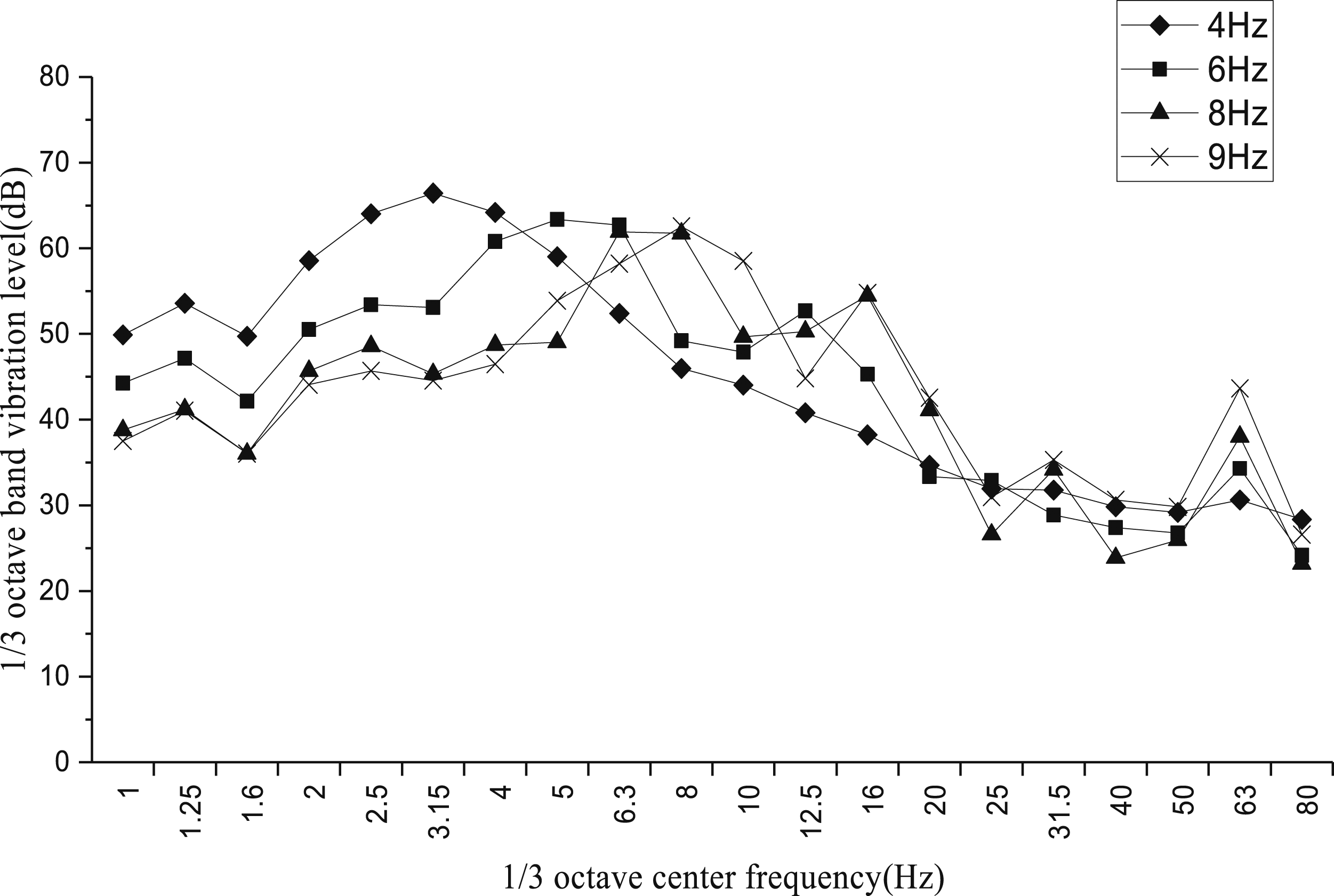
Analysis found that this was related to the vibration characteristics of joint constructions. Modal analysis of this joint construction, as shown in Figure 16, indicated the vertical vibration mass of the structure was concentrated in the 17–30 Hz range. This range accounted for 66.93% of the total vibration mass of the joint construction. When the natural frequency of the floating slab was set at 4–10 Hz, the vertical vibration mass of the joint construction was very small, with a slightly larger proportion of 0.00155% at 8.97 Hz. It can be seen from this joint construction, the use of a floating slab track with a natural frequency of 4–10 Hz can achieve a relatively satisfying damping effect. Therefore, the impact of the floating slab track in regards to the vibration characteristics of joint constructions was associated with the structural vibration characteristic, the steel spring support reaction force spectrum of the floating slab track as well as the structural vibration characteristic of the joint construction itself. Finding the optimal combination of these parameters was the key issue in developing a damping design for joint constructions. Vertical vibration mass ratio of joint construction under different structural vibration frequencies. (a) 0∼95 Hz, (b) 0∼16 Hz.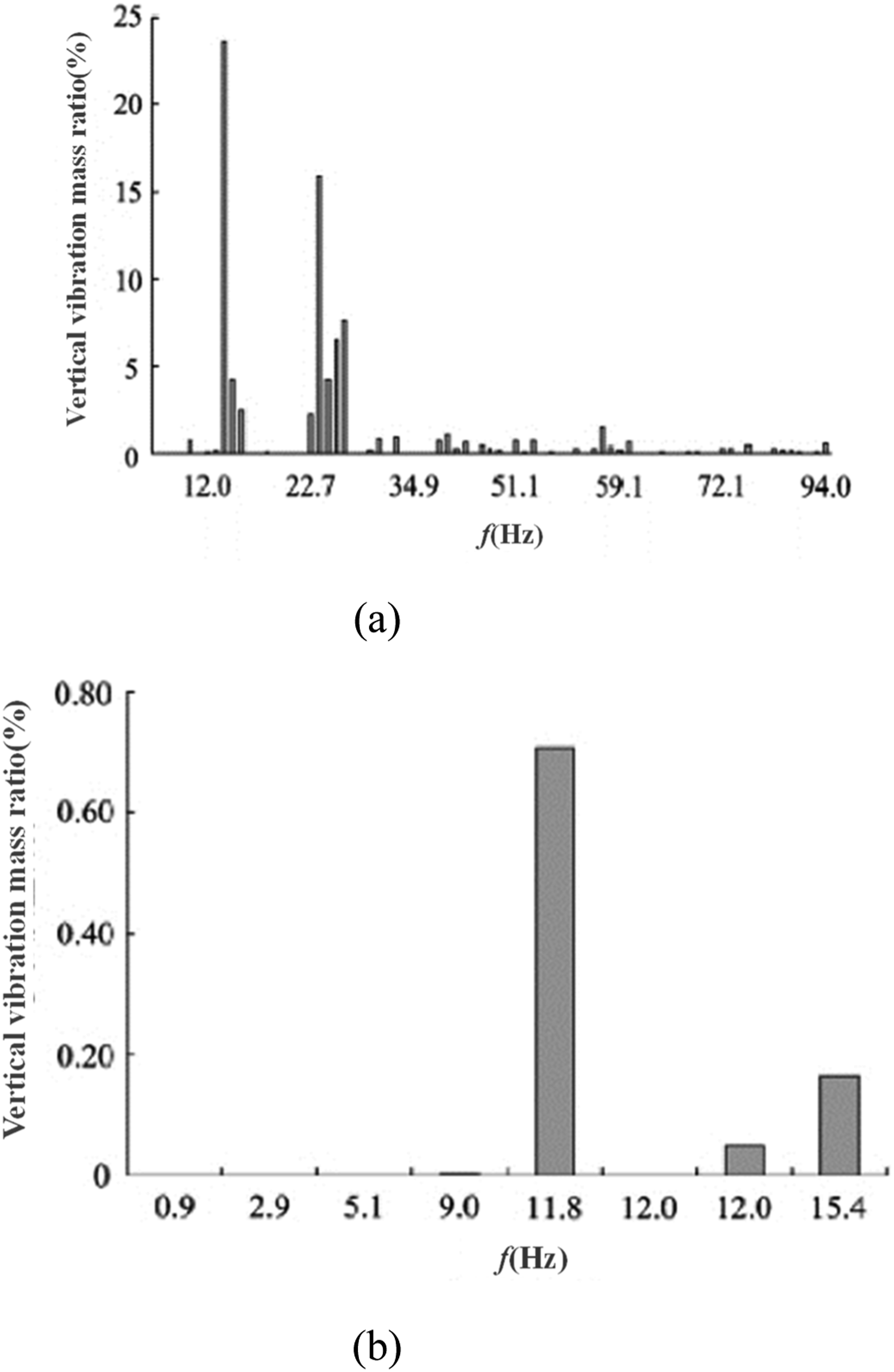
Conclusions
1. Under the structural conditions of Cologne-egg highly elastic fastener track, the duration of the vibration acceleration of the joint construction with a single train passing through was about 10–15 s, except for the platform level that had a higher acceleration amplitude (up to 0.30 m/s2). The acceleration amplitude of other levels had minor variations and the vibration frequency bandwidth was concentrated around 40–200 Hz at the platform, while the dominant frequency bandwidth of other levels was distributed between 30–80 Hz. 2. For the same measuring point, the peak vibration acceleration with the ordinary track was about twice as high as that when using the high-elastic fastener and ten times the peak by using floating slab track with a natural frequency of 6 Hz. As for the vibration duration of the joint construction with a single train passing by, the floating slab track had the longest duration while the duration was the same when using the ordinary track and high-elastic fastener track. The high-elastic fastener track and floating slab track had a certain damping effect where the former exhibited a damping advantage for frequency bands under 20 Hz, while the latter for frequency bands above 20 Hz. 3. For this joint construction project, when the natural frequency of the floating slab track was within the range of 4–10 Hz, a similar damping effect could be achieved. This was determined by the structural vibration characteristic of the joint construction when using floating slab track for damping. The structural vibration characteristic should be taken into account in order to determine the appropriate natural frequency of the floating slab track.
Footnotes
Declaration of conflicting interests
The author(s) declared no potential conflicts of interest with respect to the research, authorship, and/or publication of this article.
Funding
The author(s) received no financial support for the research, authorship, and/or publication of this article.