
Abstract
The transverse leaf spring (TLS) suspensions are a promising option for van vehicles due to their high load-carrying capacity and excellent handling stability. However, its ride comfort remains a major challenge. This paper investigates and compares the effects of semi-active and active control strategies to enhance the ride comfort of TLS suspensions. Firstly, a four-degree-of-freedom (4-DOF) half-car model and a multi-body dynamics (MBD) model of the TLS suspensions are established. The MBD model has higher accuracy and can describe the medium and high frequency characteristics of the TLS suspensions, such as the suspension offset frequency and the frequency response function of the body vertical acceleration (BVA). Therefore, based on the MBD half-car model with TLS suspensions, this paper proposes an optimal fuzzy PID active control strategy considering the left and right suspension coupling. The optimization objectives are the BVA, the left and right suspensions dynamic deflection, and the left and right wheels dynamic displacement. The integral absolute error is used as the evaluation criterion. The left and right fuzzy PID controllers’ parameters are obtained through particle swarm optimization. Simulation results demonstrate that the particle swarm optimization fuzzy PID active control strategy effectively controls the low-frequency vibration of the TLS suspensions and suppresses the medium- and high-frequency vibration characteristics compared with the traditional skyhook semi-active control strategy. This technology provides a reference for improving the ride comfort of the TLS suspensions.
Keywords
Introduction
The transverse leaf spring (TLS) has the advantages of strong loading capacity, high fatigue reliability, high roll stiffness, and small space occupation. Therefore, it has been gradually applied to the front suspensions of some light buses in recent years. At present, generally used dynamics modeling approaches of suspensions include analytical modeling (including quarter-car1,2 and half-car suspension model)3,4 and the multi-body dynamics (MBD) simulation5,6 through commercial software. The quarter-car suspension model is simple and efficient for validating unilateral suspension control strategies but cannot describe bilateral motion and roll characteristics of the TLS suspension, making coordinated control strategy simulation for bilateral dampers impossible. The half-car suspension model can address these limitations, but it simplifies TLS stiffness as linear, neglecting its nonlinearity, and does not consider the stiffness of anti-roll bars, rubber bushes, and other components. The MBD model is the preferred choice for studying suspension dynamics as it addresses the limitations of the above two dynamic models. However, its disadvantage lies in the complexity of modeling and calibration. For the MBD simulations, Adams/Car is currently widely used in vehicle dynamics modeling. 7 Therefore, two suspension models, the half-car and the MBD model, are analyzed to assess the performance of the TLS suspension.
Dynamics model simulation serves as an effective method for suspension performance analysis and structural design. Additionally, it offers a dynamic analysis platform for semi-active or active control research of traditional passive suspensions. Since TLS suspensions directly affect the handling performance and ride comfort of vehicles, this paper mainly discusses the vibration control of TLS suspension by semi-active and active suspension control strategies. A semi-active control suspension system is mainly composed of elastic elements and controllable dampers, where elastic elements are used to store energy generated by vehicle vibration whereas controllable dampers are used to dissipate energy generated by vehicle vibration. 8 The magnetorheological damper is widely used in semi-active suspension systems due to its simple structure, fast response, high dynamic range, and low power cost.9,10 Active control forces are generated directly by hydraulic or electromagnetic actuators. 11 Compared with semi-active control, active control has stronger adaptability. 12 Therefore, this study investigates the feasibility and control effectiveness of semi-active and active control strategies based on the TLS suspensions based on a controllable damping force.
In recent years, semi-active and active control strategies for different suspension types have become increasingly mature, such as the Skyhook control, 13 the sliding mode control, 14 the neural network, 15 the fuzzy logic, 16 etc. The PID controller is widely used because of its simple operation, strong applicability, and low cost. 17 While the initial parameters of PID controllers require manual tuning. Therefore, fuzzy control is introduced due to its self-adaptive advantage. 18 However, there are few studies on semi-active or active control strategies for TLS multibody dynamic suspension models. This study combines the fuzzy control strategy with the PID controller to propose an active control strategy for the MBD of TLS suspensions.
In recent years, extensive research has been conducted by numerous scholars in the field of novel intelligent optimization algorithms. These algorithms include Particle Swarm Optimization (PSO),19–21 Artificial Bee Colony Algorithm (ABCA),22,23 Cuckoo Search Algorithm (CSA),24,25 Genetic Algorithm (GA),26,27 Differential Evolution (DE) Algorithm,28,29 Dragon-Fly Algorithm (DFA),30,31 Grey–Wolf Optimization (GWO), 32 etc. The ABCA operates using forager bees, onlooker bees, and scout bees. Each generation's particle position update depends on the difference between the previous generation’s particle position and the current particle's neighborhood range. Consequently, the ABCA algorithm exhibits slow search capabilities and demands significant computational resources and efficiency. The CSA combines random step sizes with Levy flight strategies for global particle position updates. It requires more iterations for convergence, and its search mechanism is relatively random, leading to unstable search paths. The GA initially requires the transformation of variables into binary numbers, which can result in a higher risk of missing the optimal solution, especially with small sample sizes. To address this issue, genetic algorithms typically demand a large population size, leading to increased demands on computational resources, efficiency, and time consumption. The DE algorithm introduces mutation scaling and crossover probability factors, involving more parameters in the optimization process. It exhibits strong global search capabilities but requires a larger population size and, consequently, more computational resources and time. The DFA updates particle positions through a sequence of five steps, introducing numerous undetermined parameters that impact optimization results. While it considers neighboring particle velocities to some extent, it may require multiple runs to obtain stable results. The GWO algorithm replaces particle velocity updates with a hierarchical updating mechanism. However, it involves multiple tuning parameters, leading to increased demands on computational resources and time. In contrast, PSO stands out for its excellent global search capability, faster convergence, and suitability for optimizing suspension control strategy parameters.33,34 PSO offers several advantages: it performs well in high-dimensional problems, provides uniform sampling of the search space, and results in quicker convergence, shorter computation times, and resource savings.35,36 Consequently, this study selects PSO to optimize fuzzy PID controller parameters due to its computational efficiency and convergence performance.
In summary, this study aims to propose a PSOF PID active control strategy to reduce the medium- and low-frequency vibration characteristics of the TLS suspension. To comprehensively evaluate the ride comfort and handling stability of the suspension, this paper selects the suspension working space, the wheel dynamic deflection and the acceleration of the sprung mass to construct the PSO optimization objective. To evaluate the performance of the proposed PSOF PID controller, its effectiveness is compared with that of the traditional SH PID semi-active control strategy.
Dynamic models
Half-car model with TLS suspensions
The structure of the TLS suspensions is depicted in Figure 1. The upper end of the hydraulic damper is fixed on the vehicle chassis through a rubber mount, while the lower end is bolted to the knuckle. The anti-roll bar is linked to the lower control arm via the drop link. The rubber limit block's purpose is to limit the TLS suspension’s stroke. The lower control arm is connected to the hub and tire through the knuckle. Unlike McPherson suspension, the TLS suspension employs a TLS as the elastic element to replace the coil spring. The end of the TLS is connected to the lower control arm, while the middle part is fixed to the subframe via upper and lower rubber mounts. The suspension stiffness is determined by the leaf spring’s end length. Transverse leaf spring McPherson suspension. 1-Hydraulic damper; 2-Drop link; 3-Rubber Bumpstop; 4-Anti-Roll Bar; 5-Tie rod; 6-Lower Control Arm; 7-Composite Transverse Leaf Spring; 8-Knuckle; 9-Hub and Tire.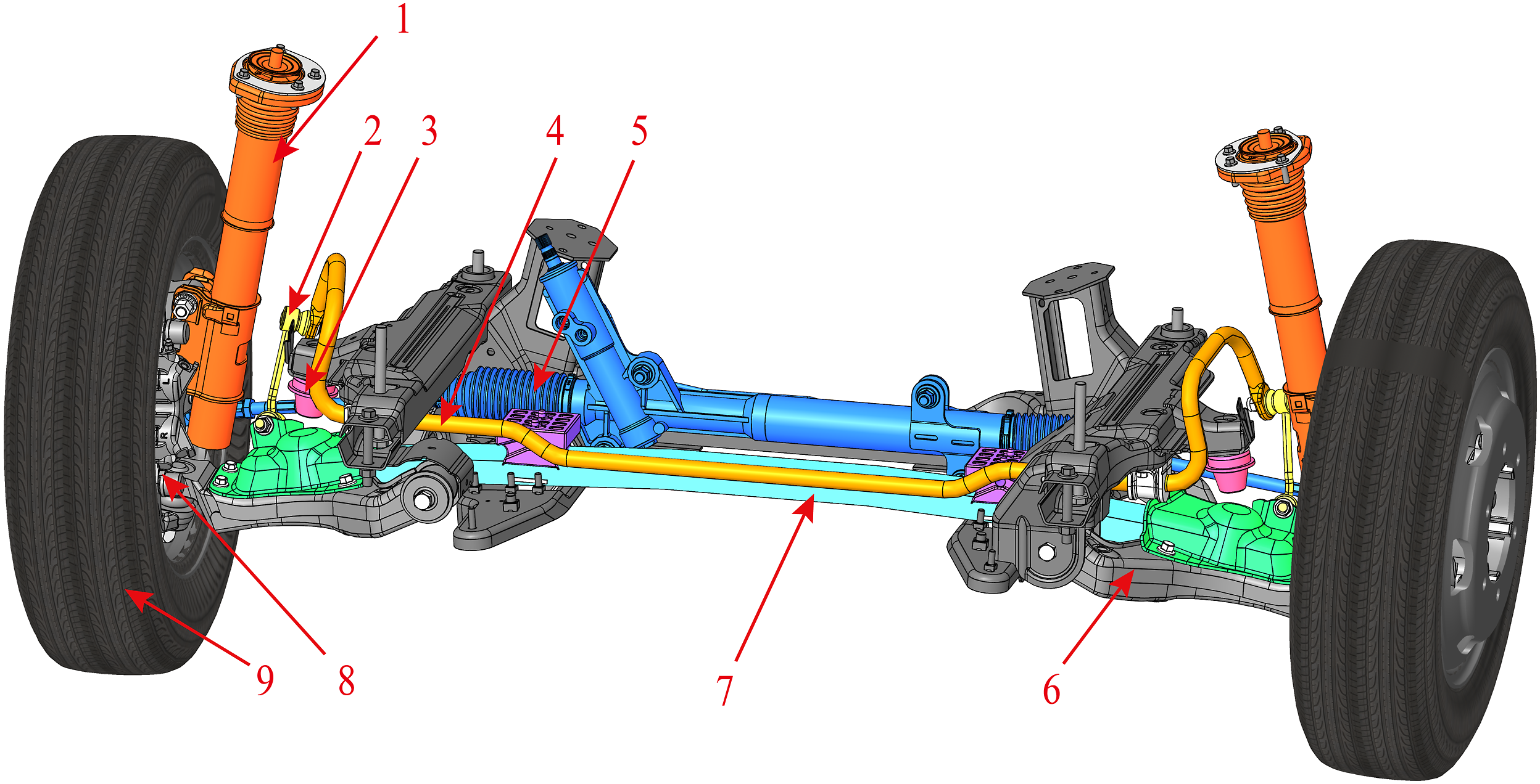
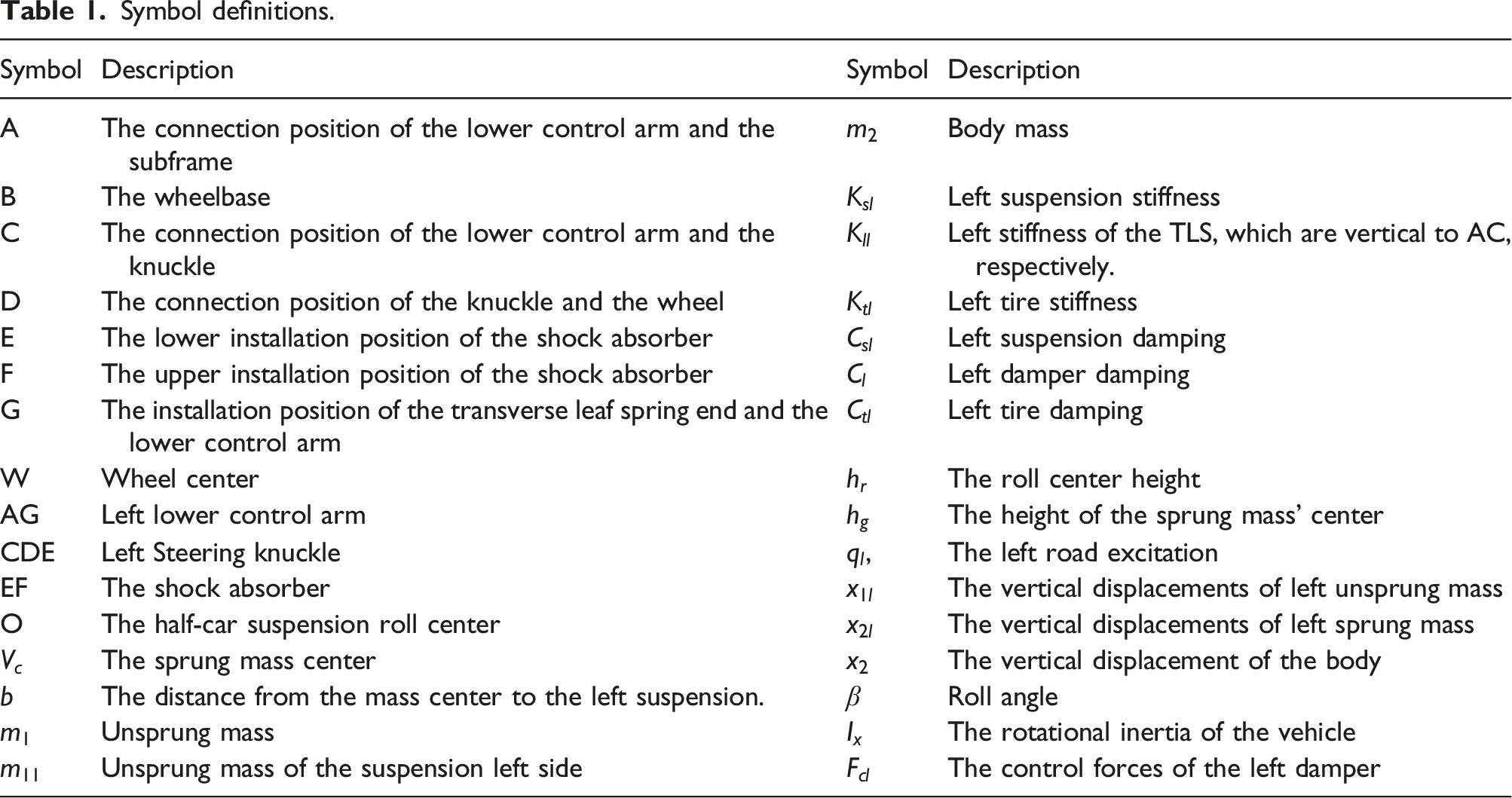
To investigate the motion behavior of the TLS suspensions, simplifications of the TLS suspensions are necessary. The dynamic model of the TLS suspensions is shown in Figure 2(a), where A, C, D, E, F, and G represent the left mounting points while the right mounting point is represented by adding “ ' ” to the corresponding parameters. Generally, the left-hand side is presented by subscript “l” and the right-hand side is indicated by subscript “r.” The symbols in Figure 2 are explained in Table 1. Due to the inability to adjust the stiffness of the TLS suspensions during movement, the adjustable damping force is employed to study the dynamic characteristics of the TLS suspensions. From Figure 2(a), it is observed that The 4-DOF half-car model for TLS suspension: (a) The dynamic model; (b) The 4-DOF half-car model. Symbol definitions.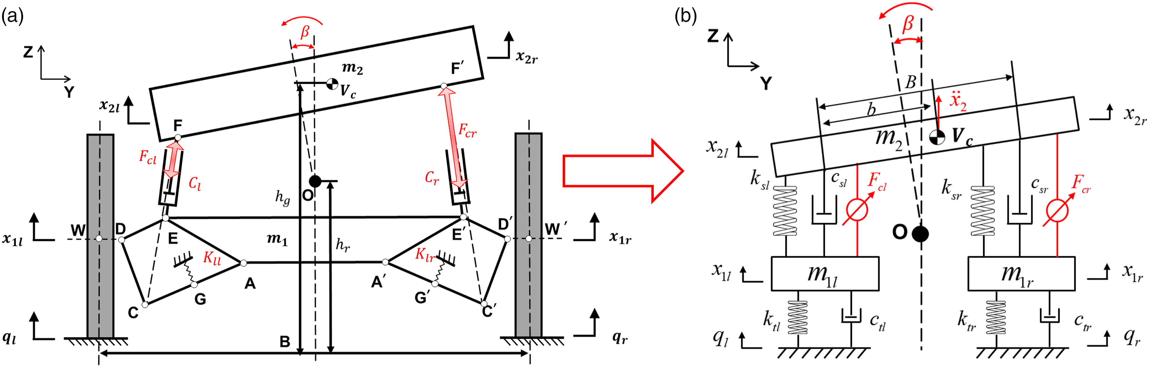
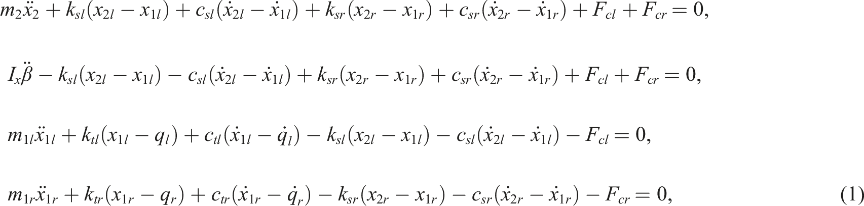
Parameters in equations of motion.
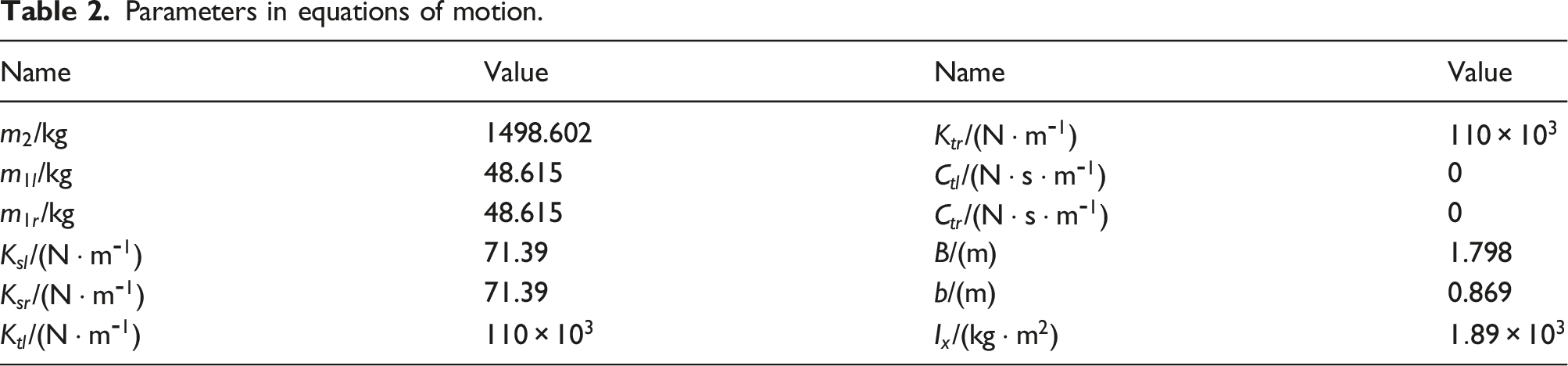
where
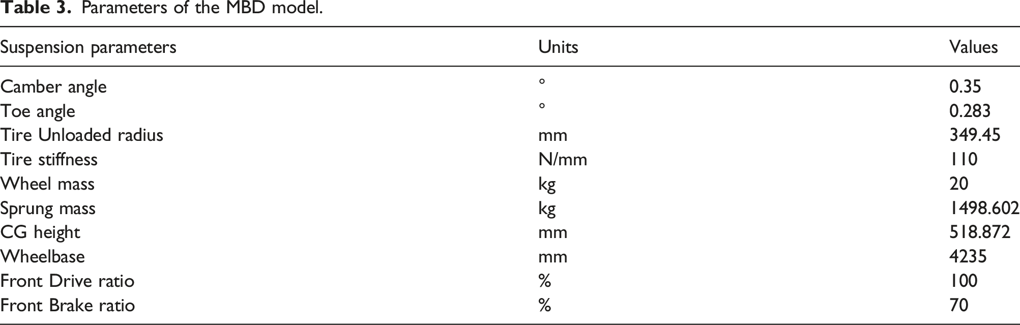
In the dynamic model, Multi-body dynamic model of the TLS suspension. Parameters of the MBD model.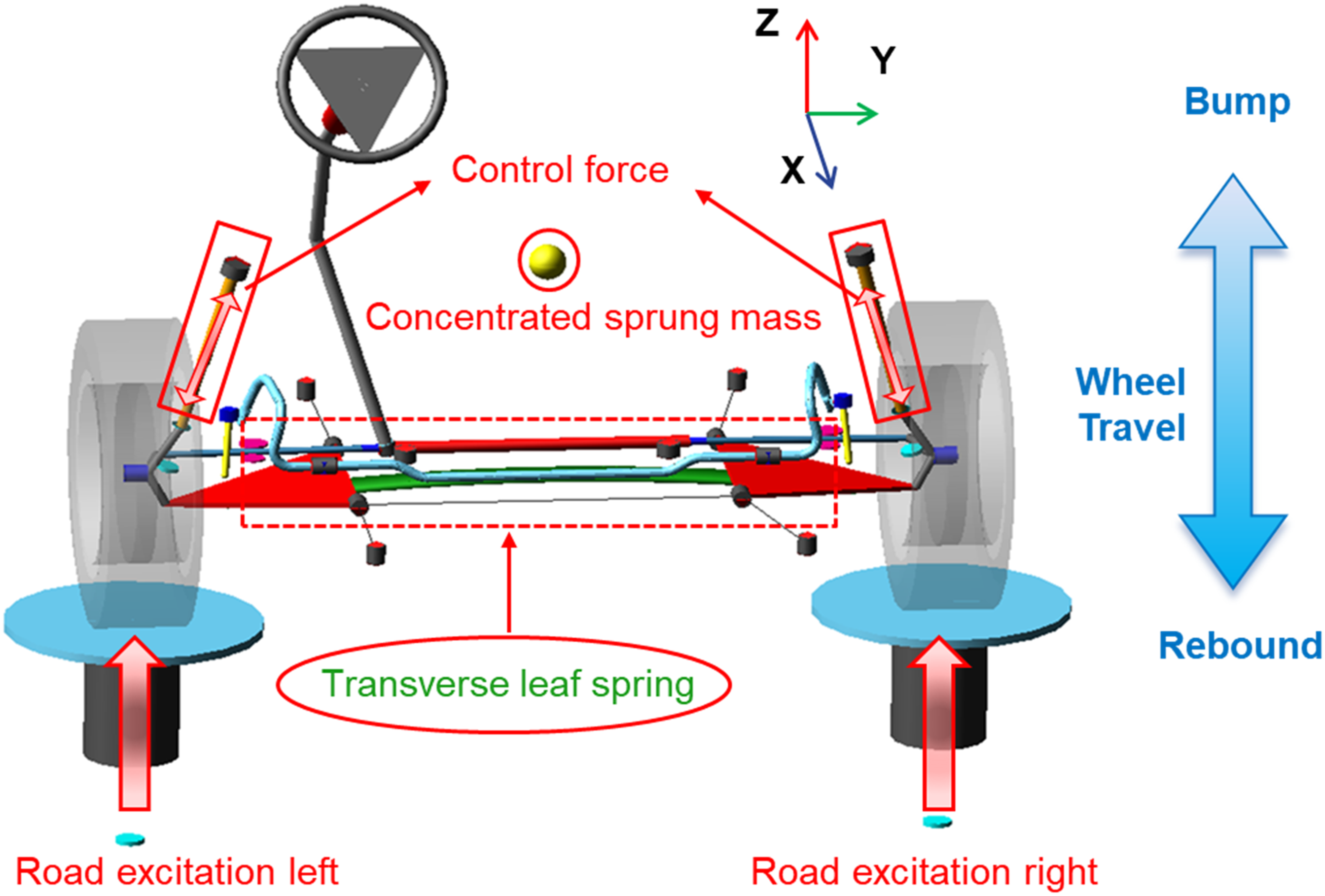
Road excitations
To investigate the differences between the 4-DOF half-car model of the TLS suspension and the MBD half-car model, a suspension offset frequency test road was established. To analyze the effects of different damping control strategies on the ride comfort of the TLS suspension, a random road model and a speed bump road model were established, respectively.
Suspension natural frequency test
To investigate the damping control strategy, it is necessary to ensure the accuracy of the TLS suspension model. According to the China National Standard GB/T 4783-1984,
37
the suspension natural frequency was tested using the roll-off method with a roll-off height of 90 mm, as shown in Figure 4(a). To simulate the suspension natural frequency of the Simulink model and Adams MBD model, a step input signal was utilized. To ensure the MBD model stays static equilibrium at the beginning of the simulation, the step began at 5 s and ended at 5.1 s, with a total simulation duration of 10 s. The step input signal is shown in Figure 4(b). Suspension natural frequency test: (a) roll-off method; (b) step input.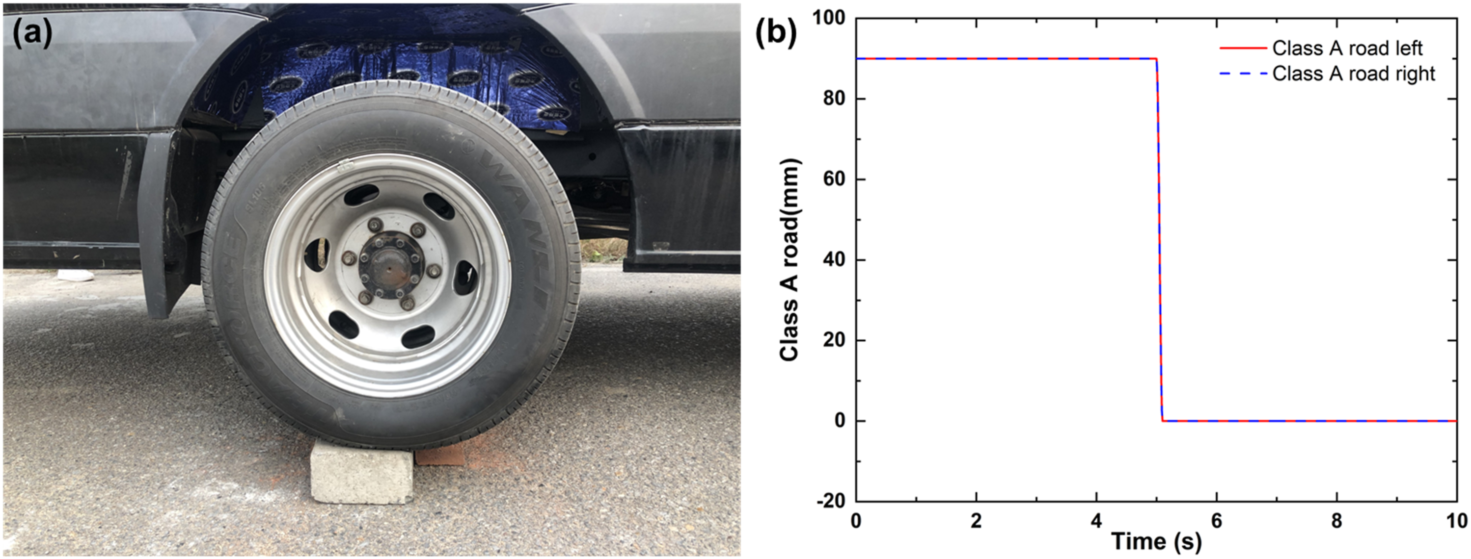
Continuous road profile
To simulate the road roughness, the Gaussian white noise method
38
is utilized and the road excitation is given as
where
The left and right road excitations are implemented by setting different intensities, where Road excitation according to ISO-8608.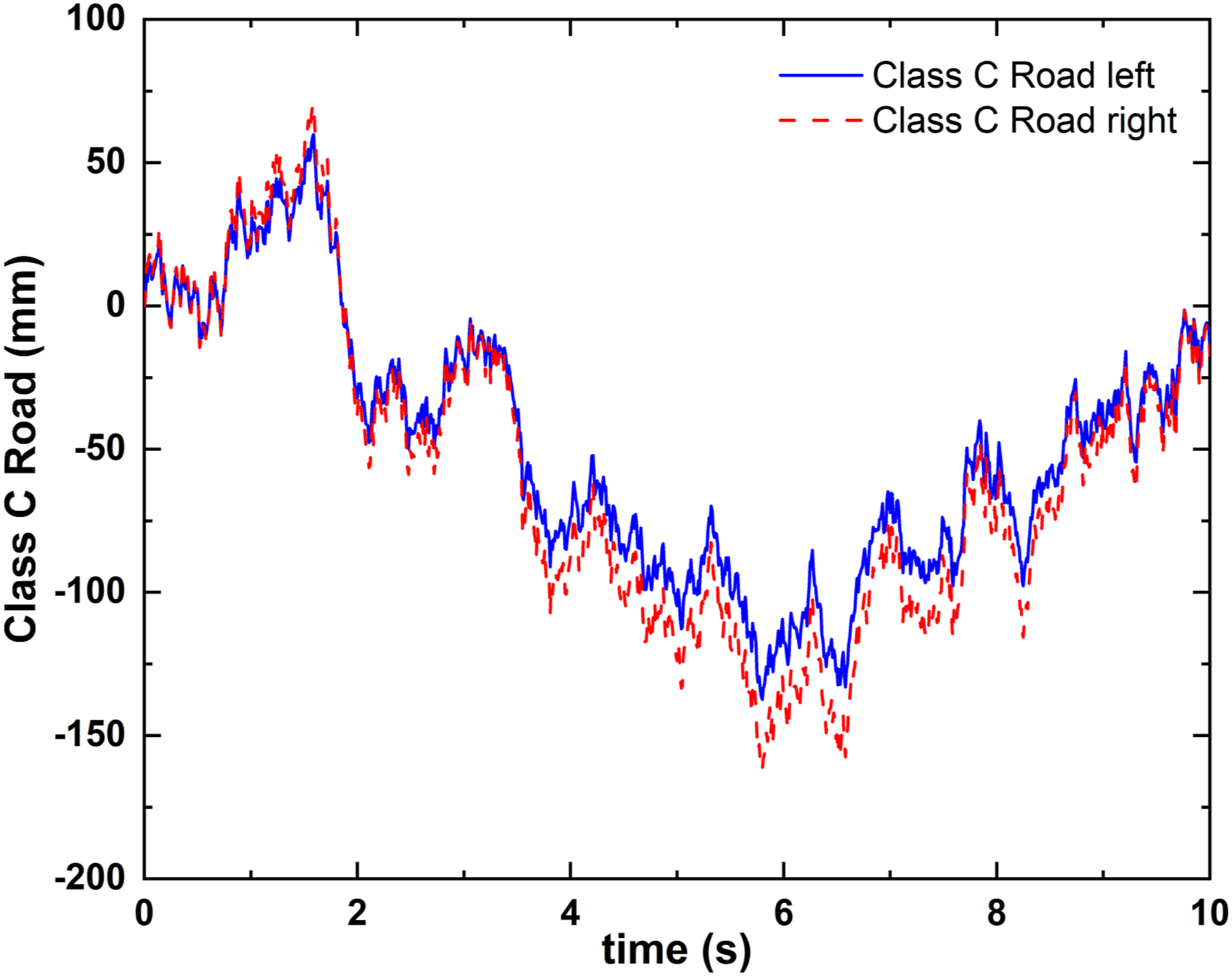
Discrete impact road
To investigate the damping control strategy of the TLS suspensions when passing over bumps or other obstacles, a trapezoidal bump was used to simulate the road impact. The spatial-domain mathematical model of the trapezoidal bump is expressed in equation (3), while the bump schematics are shown in Figure 6(a). The bump was built based on the class A road in Simulink, as shown in Figure 6(b). Discrete road impact: (a) Trapezoidal bumps; (b) Class A road impulse.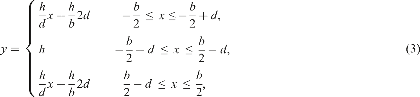
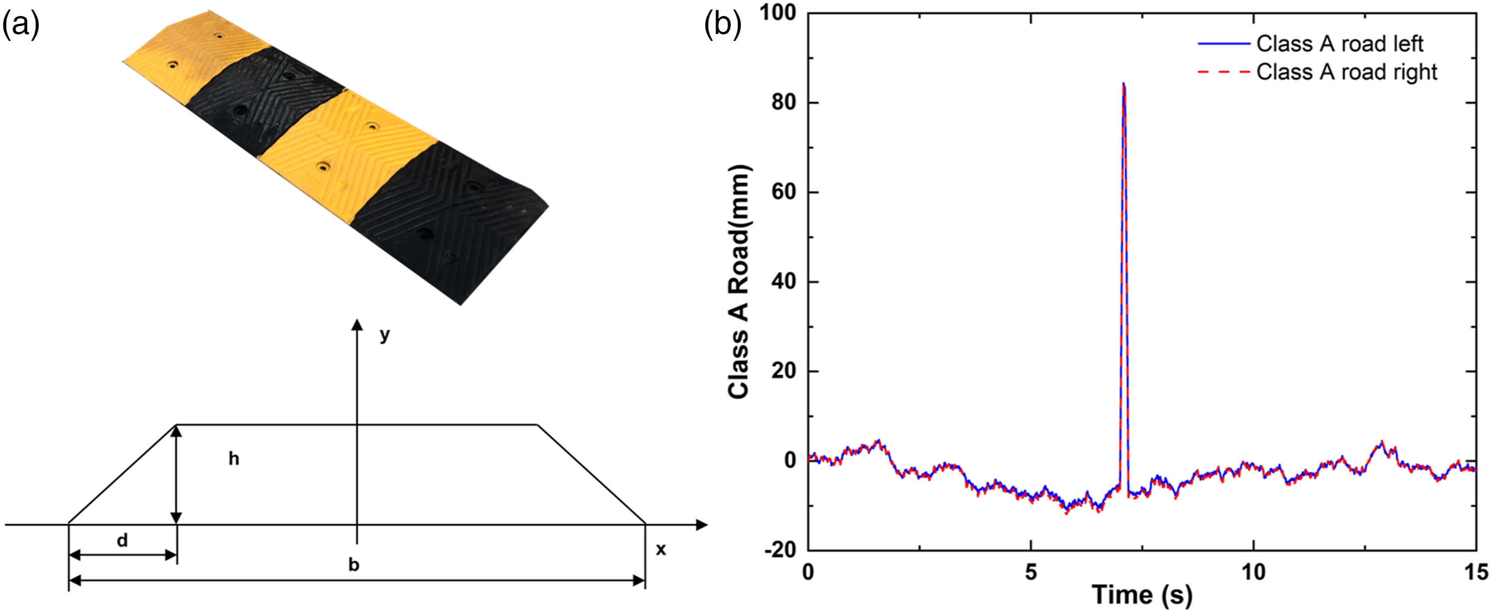
where
Control strategy and optimization methodology
The most commonly used control strategy for vehicle suspension dampers is the PID controller consisting of three parts: the proportional control (P), the integral control (I) and the derivative control (D). The mathematical expression for the PID control algorithm is as follows.
40

where PSOF PID active control strategy.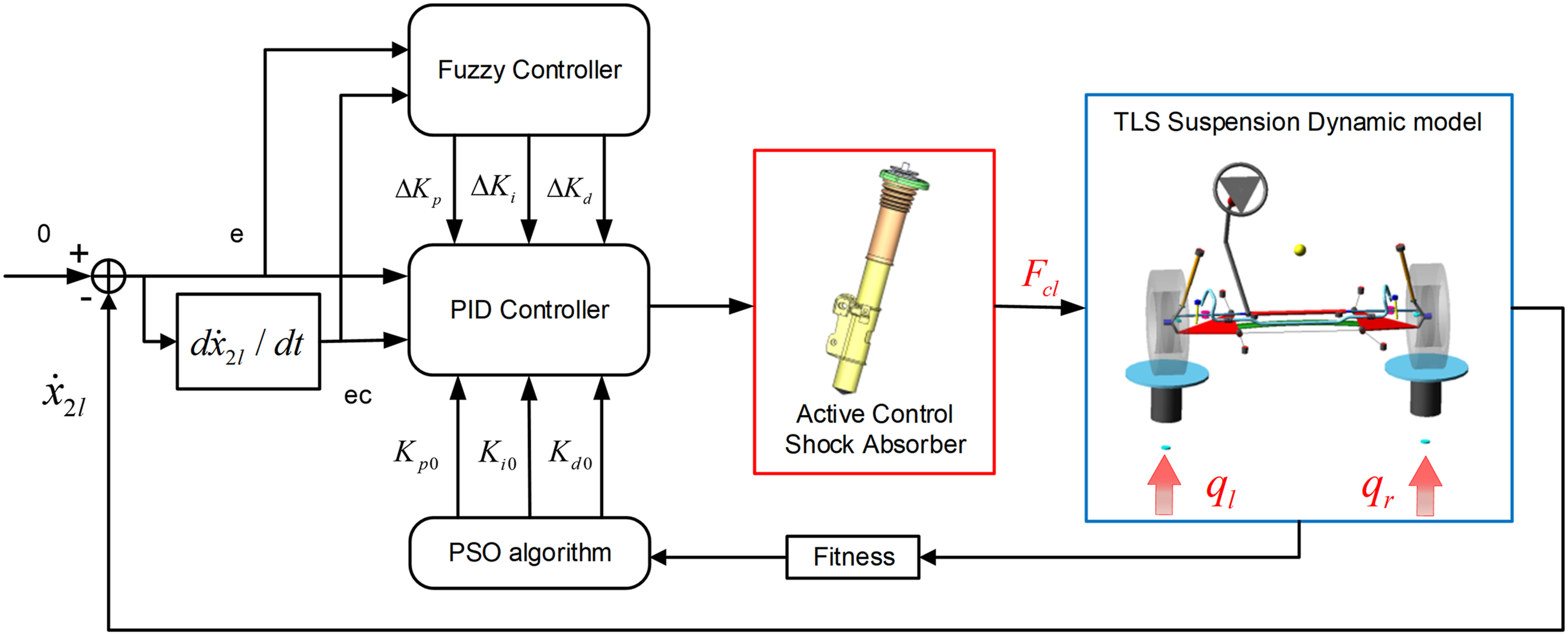
The evaluation of vehicle dynamic characteristics mainly includes ride comfort and road handling performance.
41
A good ride comfort depends on minimizing BVA and SDD. Handling is the ability of a vehicle to maintain stability on various roads, which is mainly evaluated by the WDD. In equation (4), due to the presence of the integral term 
where
This paper proposes a PSOF PID active control strategy for the TLS suspension and compares it with the traditional SH PID semi-active control strategy. The control strategy consists of two fuzzy PID controllers for the left and right sides. Taking the left TLS suspension as an example, the control structure is shown in Figure 7. When the TLS suspension is subjected to random road excitation
Semi-adaptive skyhook PID control
The skyhook control, proposed by Karnopp,
42
is a classical semi-active control strategy that assumes the presence of a virtual damper between the sprung mass and a reference fixed position (the skyhook) to suppress sprung mass vibration. Using equation (1) and taking the left damper as an example, the SH-PID controller generates the Skyhook control force denoted by 
where 
According to equation (7), the direction of the Skyhook equivalent damping force is determined by the relative velocity direction between the two ends of the damper. The body vibration is only suppressed when 
where
Adaptive fuzzy PID control
According to equation (8), the skyhook damping control force exhibits a discontinuous step phenomenon. Therefore, this paper aims to achieve the purpose of continuous adjustment of damping force based on the PID active control strategy. As traditional PID control requires trial and error to obtain 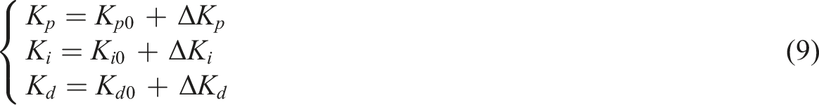
where
Fuzzy controller parameters.
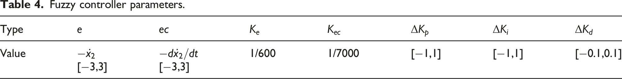
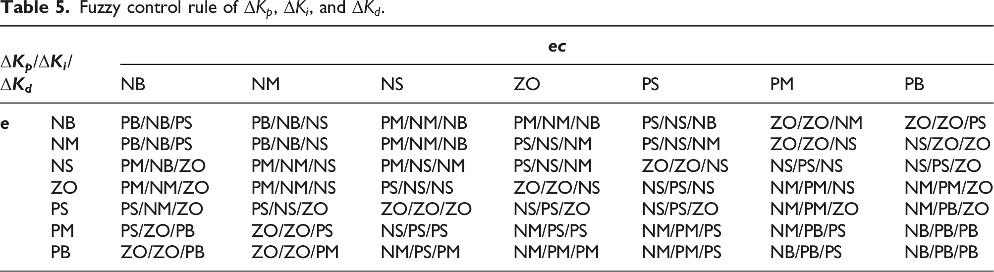
The input and output variables of e, ec, Input and output memberships of the fuzzy controller. Fuzzy control rule of 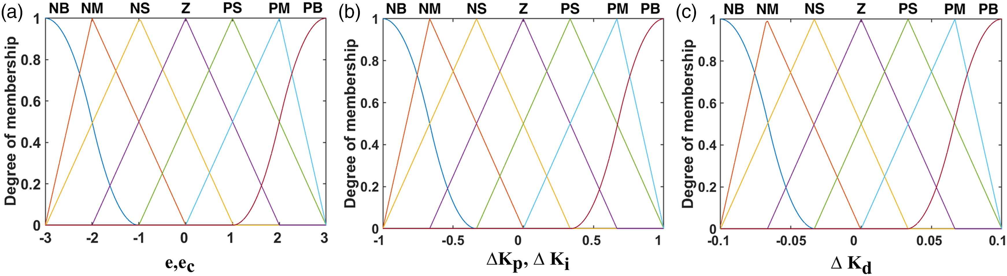
PSO algorithm
According to equation (9), it is impossible to directly determine the optimal initial values of
Assuming N particles in the D-dimensional solution space, each particle’s position 


The PSOF PID controller’s initial parameters, 
Due to the need for left and right PSOF PID controllers in the TLS suspension, the search space dimension D is set to 6. Through simulation testing, the inertia factor
The flowchart of the PSOF PID active control strategy is shown in Figure 9. Firstly, N initial particles are generated by the PSO algorithm’s random function, forming the initial particle swarm. Each particle contains 6 parameters [ Flowchart of the PSOF PID active control strategy.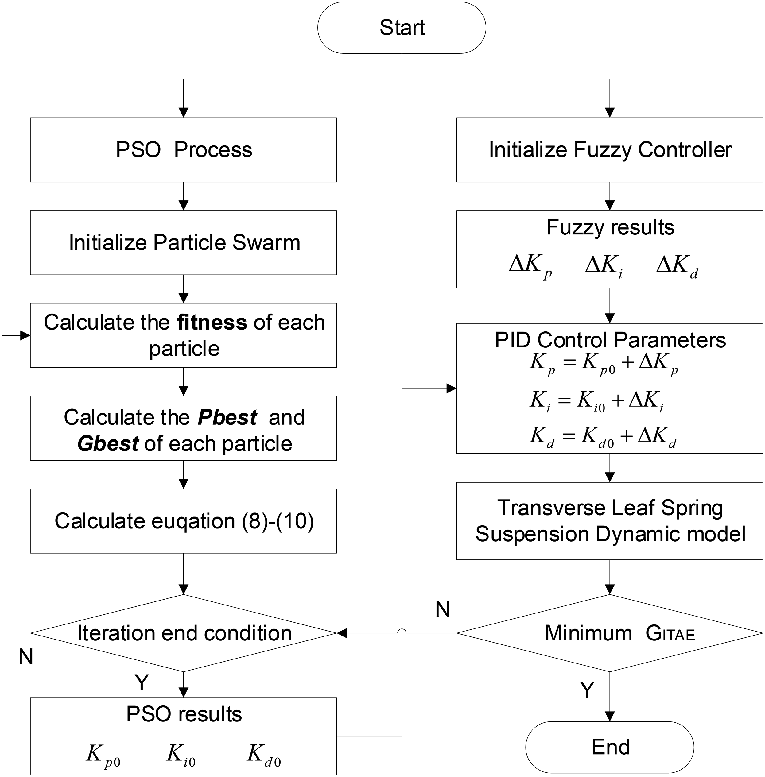
Results and discussion
Model verification
According to the suspension offset test, the comparison between the BVA Roll-off test of suspension natural frequency: (a) left BVA; (b) FFT of left BVA.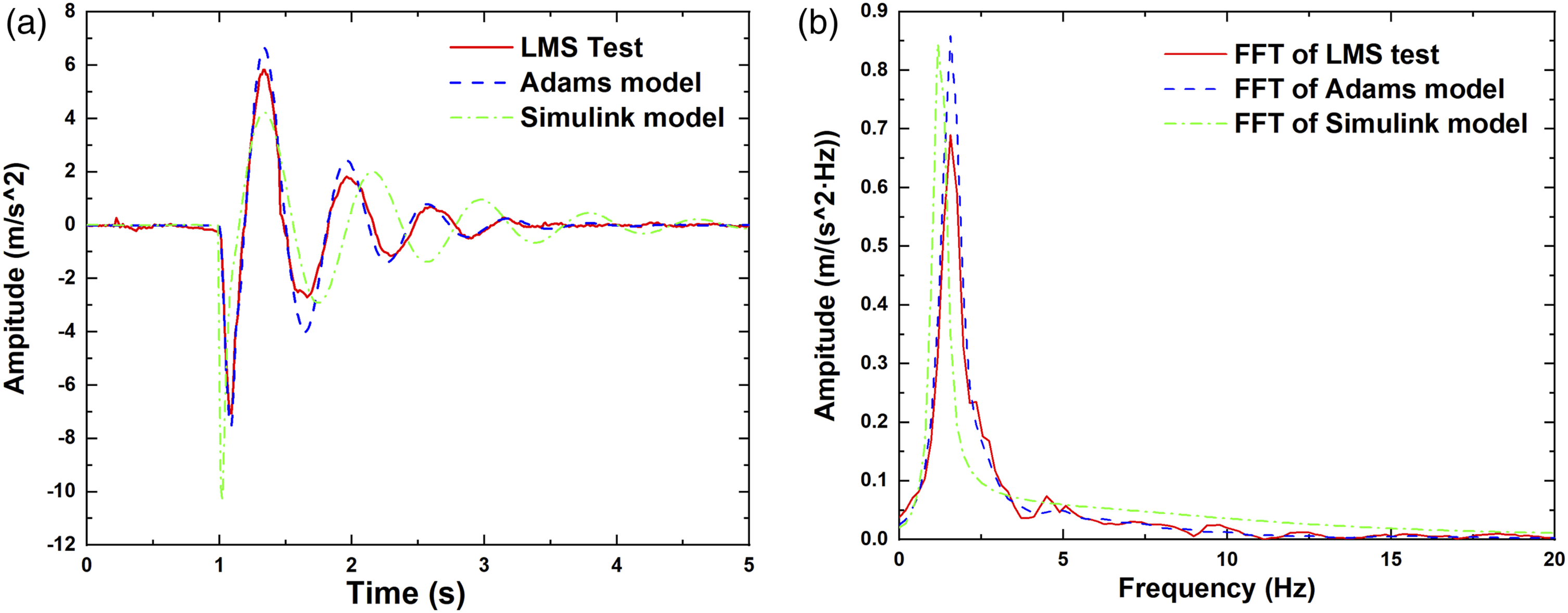
The Simulink dynamic model and the Adams MBD model are compared on a class C road, as shown in Figure 11. The root mean square (RMS) values of the BVA Comparison between the Adams MBD model and the 4-DOF model of TLS suspension: (a) BVA on C class road; (b) BVA Bode plots.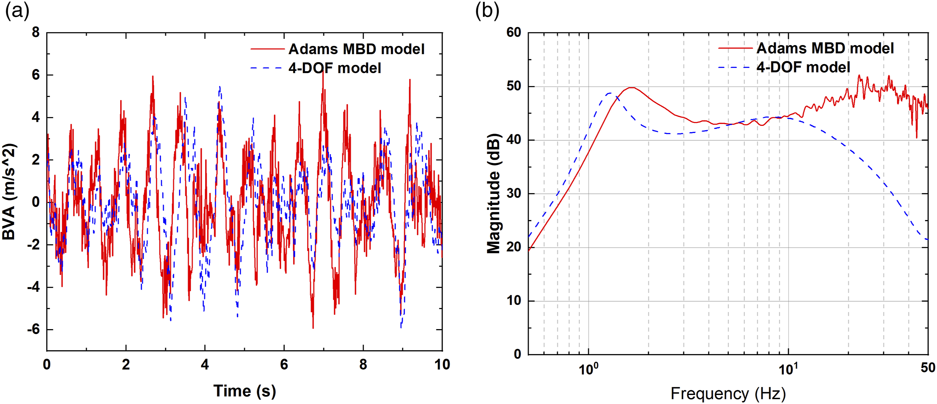
Continuous road simulation
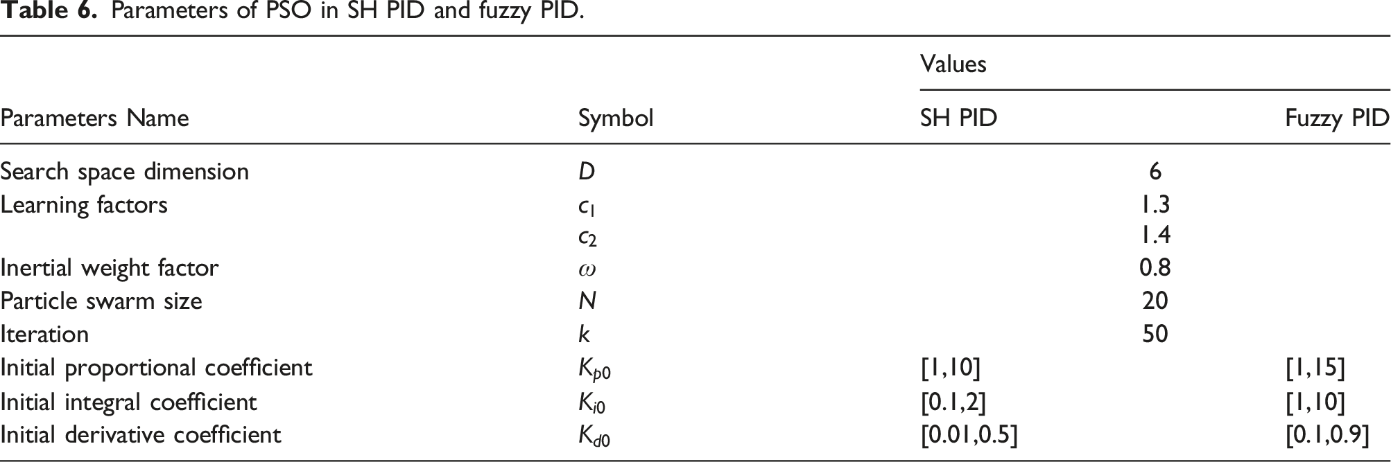
Parameters of PSO in SH PID and fuzzy PID.
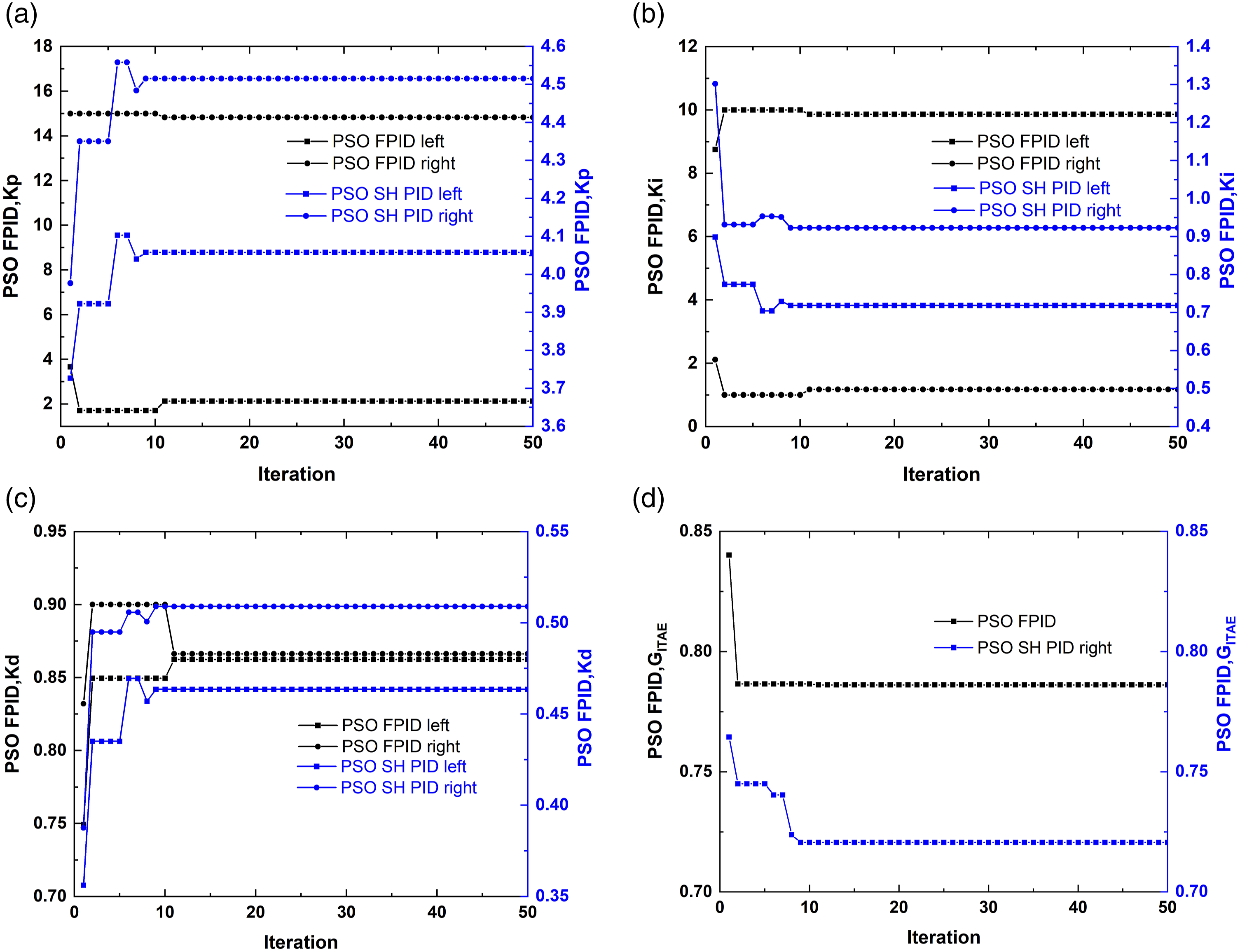
PID parameters tuning results using PSO algorithm under continuous road: (a) PSO optimizing K p ; (b) PSO optimizing K i ; (c) PSO optimizing K d ; (d) PSO optimizing G ITAE .
The optimal parameters of the two controllers were applied to the model for computation, and the results are depicted in Figure 13. The results show that the PSO SH PID semi-active control strategy has a limited vibration reduction effect in the low-frequency range and intensifies vibration at higher frequencies. The PSOF PID active control strategy is effective in reducing vibration in the low-frequency range, but its effectiveness is limited in the high-frequency range. Frequency response of road input to BVA.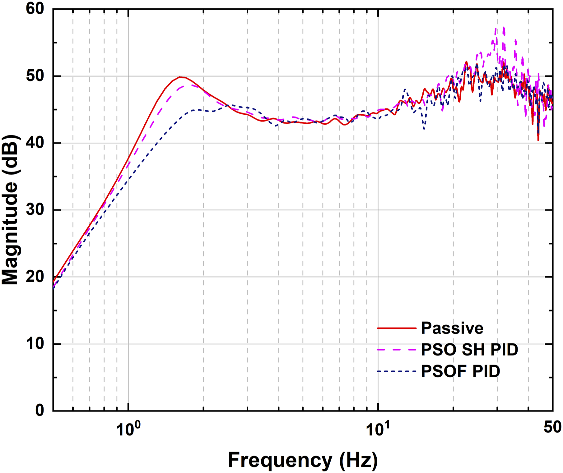
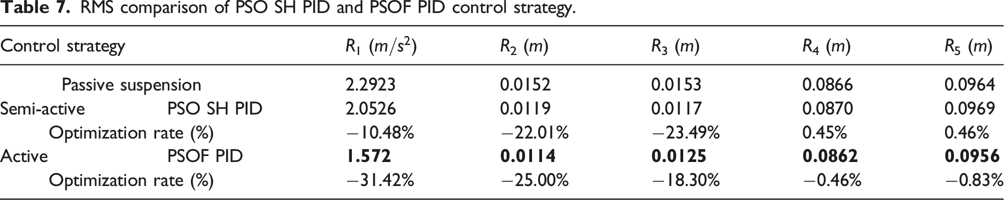
Figure 14 compares the control effects of semi-active and active control strategies on class C roads. Results show that the PSOF PID active control strategy significantly improves the low-frequency characteristics of the BVA, reducing the maximum amplitude at 1.6 Hz by 87.86% and at 1.9 Hz by 52.62%. The PSOF PID active control strategy is superior to the SH PID semi-active control strategy in controlling the BVA and SDD, reducing the RMS amplitude of BVA by 31.42%. Table 7 shows that the PSOF PID active control strategy has the best SDD control effect. These two control strategies have similar WDD control effects. Comparison of semi-active and active control effects on class C road: (a) BVA; (b) PSD of BVA; (c) Left SDD; (d) Right SDD; (e) Left WDD; (f) Right WDD. RMS comparison of PSO SH PID and PSOF PID control strategy.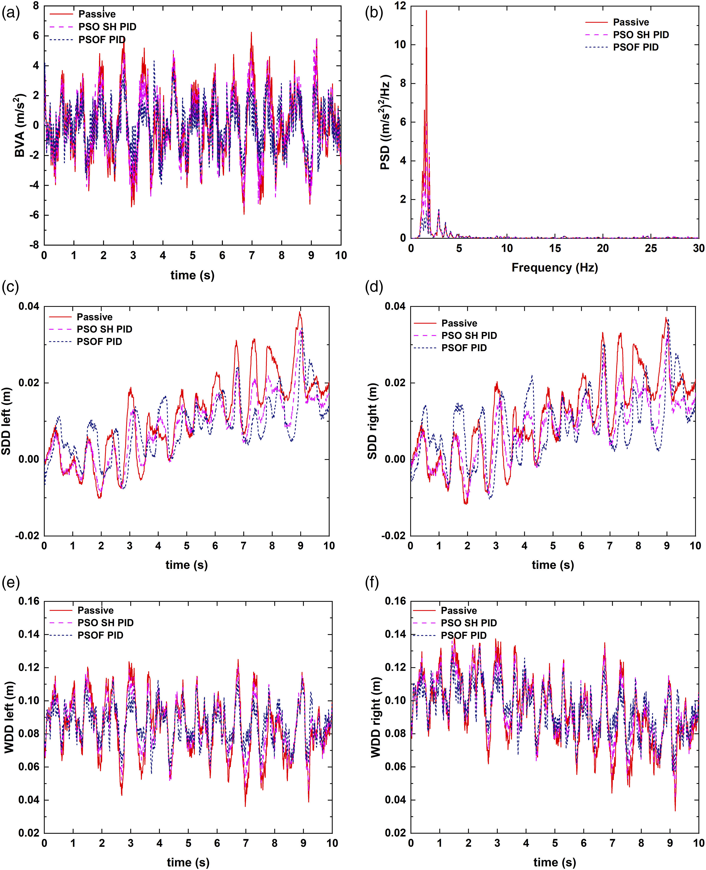
Discrete impact road simulation
Under discrete impact road excitations, the parameters of the SH PID and Fuzzy PID controllers were optimized using the PSO algorithm, following a similar iterative process as shown in Figure 12. The optimal parameters for each controller were subsequently applied to their respective models. A comparison of the SH PID semi-active and PSOF PID active control strategy on a discrete impact class A road at 2 m/s showed that the PSOF PID active control strategy has the best vibration reduction control effect, as seen in Figure 15. The low-frequency vibration of the sprung mass has been greatly improved. Comparison of semi-active and active control effects on a discrete impact class A road: (a) BVA; (b) PSD of BVA; (c) Left SDD; (d) Right SDD; (e) Left WDD; (f) Right WDD.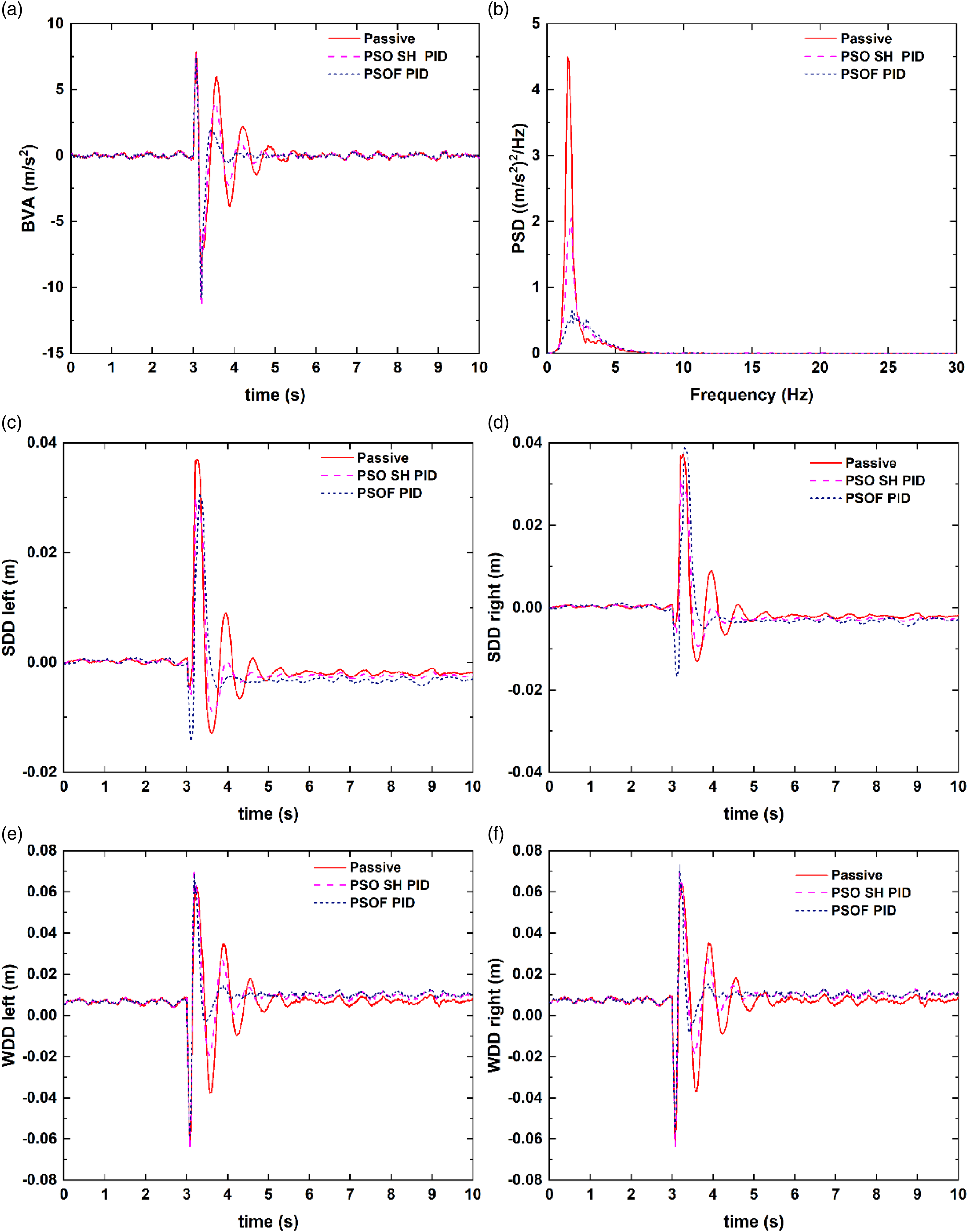
Conclusion
To study the control algorithm of TLS suspension, the Simulink 4-DOF model and Adams/Car MBD model are established. The 4-DOF model has a small suspension offset frequency and cannot describe the high-frequency characteristics of the TLS suspension. Therefore, an Adams/Car MBD model of the TLS suspension was established, where the TLS was modeled using the discrete beam method.
A PSOF PID adaptive active control algorithm for half-car TLS suspension is proposed, with the body’s vertical velocity as the control variable. The fuzzy control is used to adapt the traditional PID controller parameters, and PSO is used for multi-objective optimization of the initial value of the TLS suspension fuzzy controllers. Under class C random roads, the PSOF PID active control improves the low-frequency characteristics of the BVA and slightly suppresses high-frequency vibration. Traditional SH PID semi-active control strategy exacerbates medium- and high-frequency vibration. The PSOF PID active control strategy reduces the RMS value of BVA by 31.42% and PSD amplitude by 87.86%. Under class A discrete impact road, the PSOF PID active control strategy greatly improves TLS suspension BVA, SDD, and WDD, demonstrating its suitability for vibration suppression of the TLS suspension.
The implementation of the PSOF PID control strategy has significantly enhanced the ride comfort of vehicles equipped with transverse leaf spring suspension. Analysis of the BVA Bode diagram indicates that the proposed PSOF PID demonstrates exceptional control performance, particularly in terms of low-frequency control effectiveness. However, further improvements are required to enhance the control effectiveness in the high-frequency range. Therefore, future research endeavors should focus on optimizing the placement of the active controller and developing novel optimization algorithms to enhance the overall frequency control performance of the transverse leaf spring suspension.
Footnotes
Declaration of conflicting interests
The author(s) declared no potential conflicts of interest with respect to the research, authorship, and/or publication of this article.
Funding
The author(s) disclosed receipt of the following financial support for the research, authorship, and/or publication of this article: The authors gratefully acknowledge Project 51705357 supported by the National Natural Science Foundation of China, Project 18JCYBJC20000 supported by the Natural Science Foundation of Tianjin and Project 2021T140519 supported by the China Postdoctoral Science Foundation.