
Abstract
In this work, a dynamic model considering time-varying mesh stiffness and backlash was proposed and a test rig was built to investigate the vibration behavior of the idle gear set in a gerotor pump. The effects of input shaft speed, torque fluctuation, and gear tooth backlash on the dynamic performance of gerotor pump were analyzed according to the numerical and experimental results. Results demonstrate that when the torque fluctuation is neglected, the dynamic transmission error of drive gear is dominated by the first three mesh harmonic components; however, the RMS values of vibration acceleration have high frequency characteristics. When the torque fluctuation is considered, the dynamic responses of gerotor pump are modulated by the torque fluctuation. The effect of tooth backlash on the dynamic performance of gerotor pump is limited and mostly depended on the torque fluctuation condition. The gerotor pump noise is dominated by the low frequency component around the mesh frequency. The vibration energy can be divided into two parts in the frequency domain. In the low frequency band, the vibration energy is caused by the mechanical vibration. However, in the high frequency band, the cavitation phenomena may cause the concentration of the vibration energy and resonant of pump structure.
Introduction
Gerotor pump is generally used in lubrication circuit in the automotive internal combustion engine. In this application, the gerotor pump is driven by mechanical transmission system such as a gear set or are directly connected to the ICE crankshaft as the table lubricant supply ensures normal and efficient operation of the internal combustion engine. However, almost all pumps are subjected to cavitation, which can disturb the oil flow and make the drag torque fluctuation. On the other hand, the gear set may also produce vibration and noise issue, which become more important in the automotive application. 1 Furthermore, the fluctuation of the drag torque due to cavitation may interfere with the mating process of gear pair and deteriorate the noise problem. Hence, we focus our attention on the coupled dynamic performance of a gerotor pump with a gear drive in the present work.
In recent years, many researchers have devoted to the performances of the gerotor pump especially on the object of geometric analysis and flow analysis. For example, Kini et al. 2 optimized the design of cover plates, including placement of bolts, to reduce deflection and also cavitation of gerotor pump. Hsieh 3 analyzed the rotor sealing, contact stress, area efficiency, and outlet pressure with various geometrical design parameters by using curvature difference method. Yang et al. 4 presented geometrical formulas to calculate flow rate of gerotor pumps based on the deviation function method. Kumar and Manonmani 5 have numerically and experimentally investigated the performance of gerotor pump. Their result indicates that the inlet pipe size, strainer porosity, and port sizing can affect the suction capacity, the flow velocity, and the efficiency of the gerotor pump. Ravari et al. 6 proposed a method to optimize the volumetric, dynamic, and geometric properties and to reduce the flow rate irregularity and wear rate. Jamadar et al. 7 optimized the suction and delivery port to reduce the pressure and flow pulsation of gerotor pump.
On the other hand, many works also have been done by measuring the flow pressure, vibration, and noise signals. Čudina 8 detected the cavitation behavior in a centrifugal pump using audible sound. Adamkowski et al. 9 found that the main cause of fractures of the pump shafts in a coastal power plant was the resonance of torsional vibration of the shafts following from considerable loss of impellers mass due to excessive cavitation erosion during normal work of the pumps. Buono et al. 10 studied the method to detect and predict the cavitation in gerotor pumps through an experimentation phase and a vibrational analysis. Siano et al. 11 carried out a full experimental investigation of the vibration features and cavitation phenomenon of a gerotor pump used for the lubrication of automotive engine. Sun et al. 12 analyzed the vibration signals of a centrifugal pump using the HHT method and found that torque oscillation caused by unsteady flow during cavitation process could result in energy variation. Battarra and Mucchi 13 studied the cavitation characteristics in external gear machines by means of a dedicated experimental campaign and discussed the effect of oil temperature. Their main objective is to explore the existence of cavitation of gerotor pump, and its effect on the pressure pulsation, vibration characteristics, and noise level. However, there is rarely reference to investigate the dynamic characteristic of a gerotor pump with a gear drive. Fernández-del-Rincón et al. 14 proposed an enhanced dynamic model to study the vibration behaviors of gear transmission in presence of index and run out errors. Rook and Singh 15 investigated the non-linear vibration features of a reverse-idler gear pair with concurrent clearances analytically using Galerkin and Floquet methods. Kahraman 16 proposed a three dimensional dynamic model including transverse, torsional, axial, and rotational motions of a multi-mesh helical gear train with one of the gears in mesh with the other two and analyzed the dynamic responses. In recent decades, the modeling methods of gear dynamics are becoming increasingly precise.17,18 Hu has established a spur gear system that considers thin-walled webs,19,20 and Tian establishes a transmission system that considers the web and tooth structure of bevel gears. 21 There are many studies on the dynamics of gear transmission systems, but there are few literature studies analyzing and studying together with gerotor pumps
These investigations show that gear drive could induce certain vibration and noise problem like rattle and whine noise Therefore, in this paper, a dynamic model, to simulate the dynamic performance of gear drive with the effect of the torque fluctuation due to cavitation of gerotor pump, is proposed firstly. And then, a test rig to measure the noise and vibration data of the pump is developed. The influences of input shaft speed, torque fluctuation, and tooth backlash on the dynamic characteristics are analyzed based on the numerical simulation results and the experimental measured signal. Finally, some conclusions are summarized.
Dynamic model and test rig of gerotor pump
Dynamic model of gear drive
The gerotor pump investigated in this work is an internal gear pump used in the lubrication system of internal combustion engines. As shown in Figure 1, the gear drive system of the gerotor pump is comprised of three gears including an input gear, an idle gear, and an output gear. The pump also consists of an outer rotor with 4 teeth and an inner rotor with 5 teeth. Gerotor pump.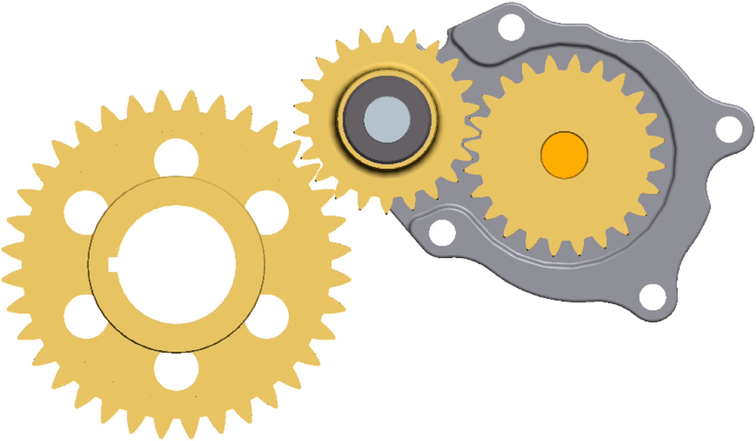
The schematic of the lumped parameter dynamic model of this idle gear set is illustrated in Figure 2. In this figure, Lumped parameter dynamic model of the idle gear set.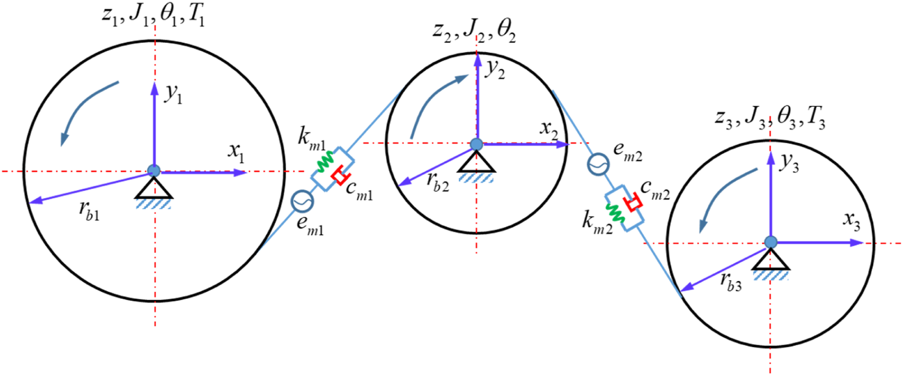
The governing equations for the idle gear set are,


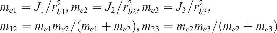
Letting,


Mesh stiffness and transmission error excitations
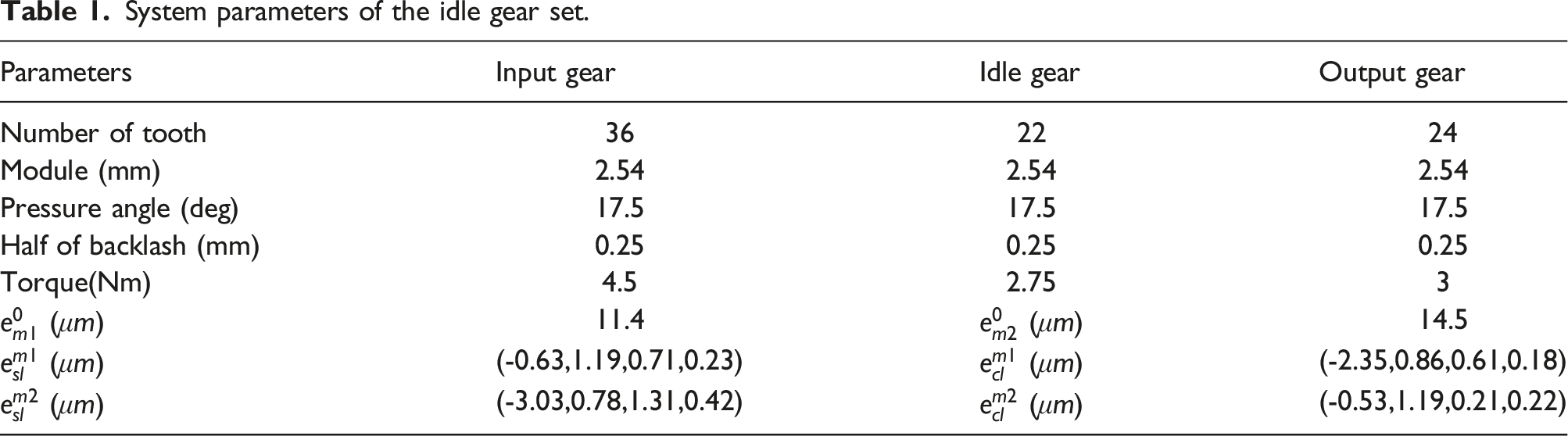
System parameters of the idle gear set.
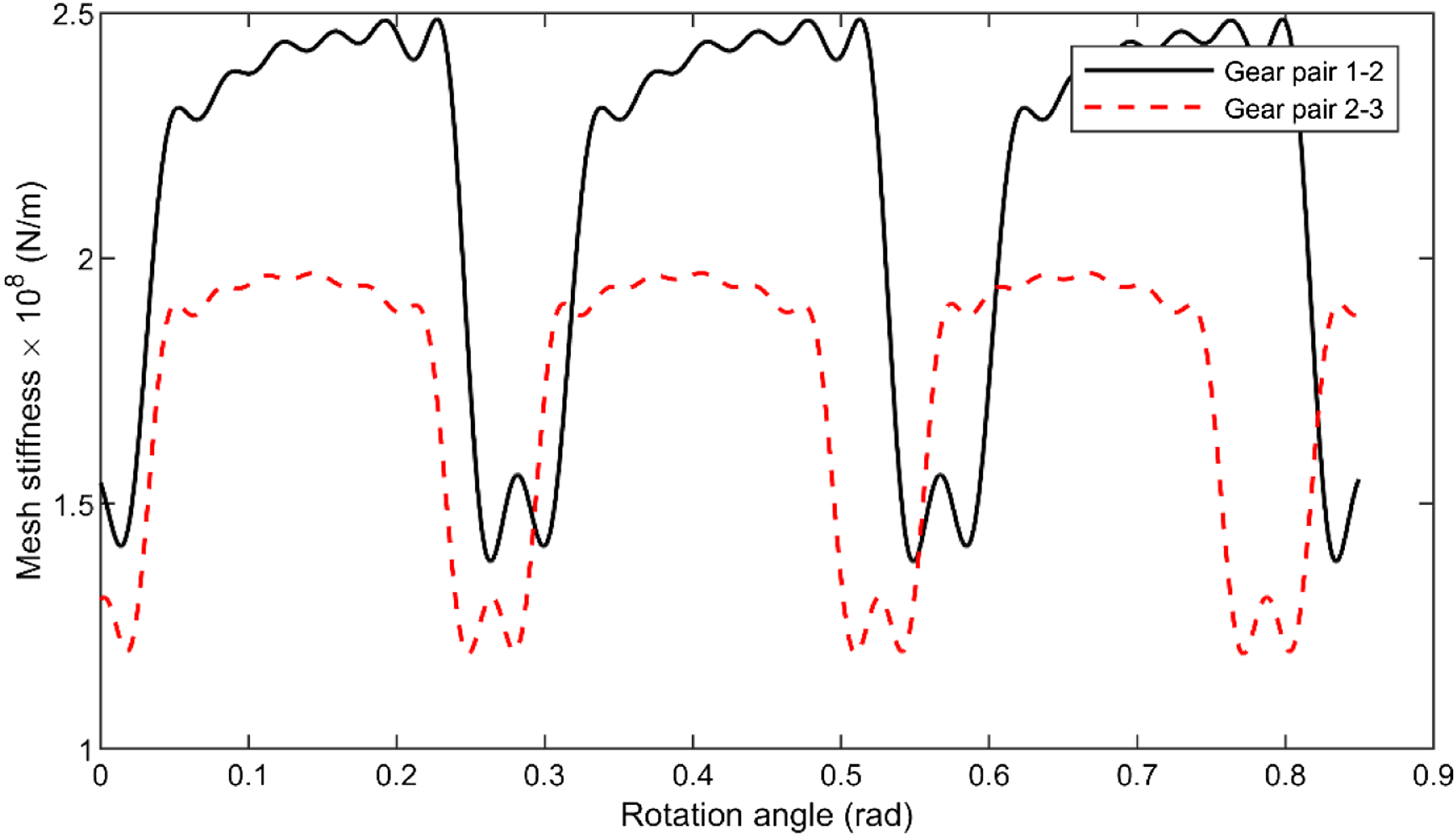
Mesh stiffness of gear pairs.
In dynamic analysis, a Fourier series of the mesh stiffness is general adopted as,

The profile deviation of tooth can be modeled as the unloaded static transmission error excitations, which can also represent as


Test rig of gerotor pump
A test rig is also applied to investigate the vibration behaviors of the gerotor pump from the view of experiment. As shown in Figure 4, a three phase electric motor with 4 poles is used and the pump shaft rotation speed is varied through an electrohydraulic regulator handled by a dedicated card. An optical encoder was located at the input shaft to measure the rotation speed, which is also the shaft speed of input gear Test rig of gerotor pump.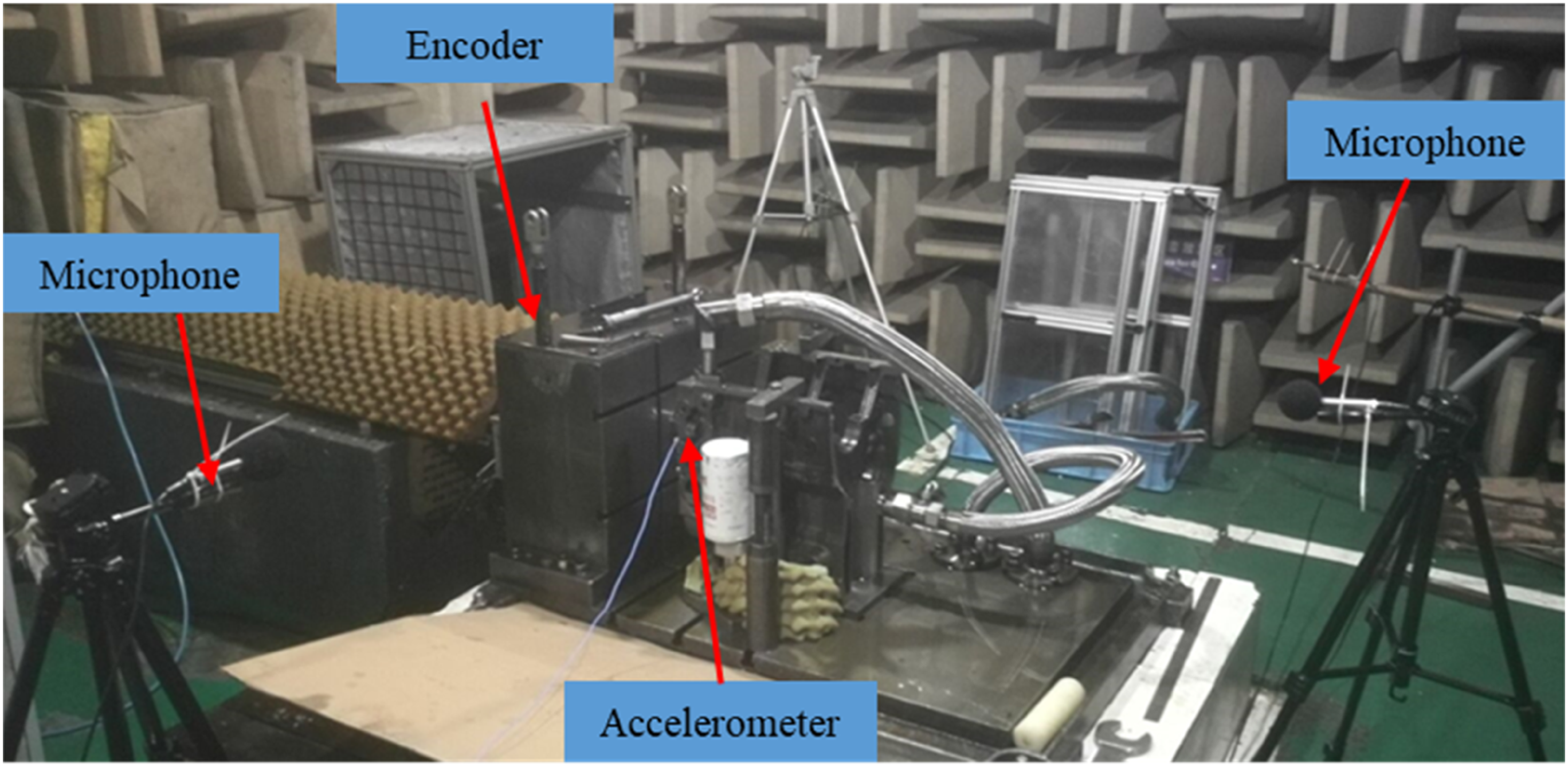
Dynamic responses of gerotor pump
In this section, the dynamic responses of the idle gear set are investigated based on the governing equations (7) and (8). The drag torque is 3 Nm, the four damping ratios are set to 0.07, and half of the normal backlashes of the two gear pairs are 0.25 mm. The accuracy levels of the gear pairs are grade 7 and the related unloaded static transmission error defined as an excitation can be deduced from the parameters of gear precision. Then the governing equations are solved by using Runge–Kutta numerical integration method within the 500 mesh periods. The first 300 mesh periods are neglected and the steady state responses are used to indicate the dynamic characteristics. In the numerical analysis, the dynamic transmission error (DTE) and corresponding acceleration of the gear pairs are chosen as the dynamic response parameters to investigate the vibration characteristics of the system. Here, the dynamic transmission error responses are defined as the displacements along line of action of the gear pair, which can be given as
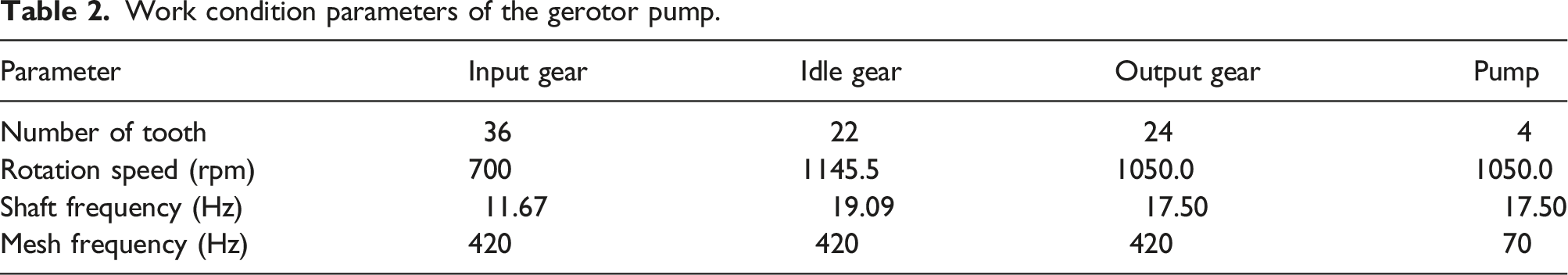
Work condition parameters of the gerotor pump.
Effect of input speed
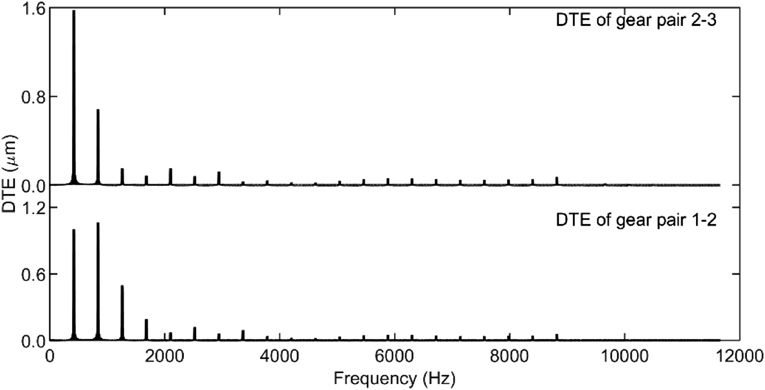
In this subsection, the input shaft speed is set to 700 rpm, and the gear eccentricity and drag torque fluctuation are neglected. The dynamic transmission error and corresponding acceleration of the gerotor pump are shown in Figure 5. Their corresponding spectra are also shown in Figure 6 and Figure 7, respectively. It can be seen from these figures that the DTE of the input and idle gear pair is dominated by the first three mesh harmonic components as the torque fluctuation is not considered. However, many high order components are detected and the phenomena similar to modulation are observed in the frequency diagrams of Acc. responses. By comparing with Figure 3, one can find the high frequency component is related to the mesh stiffness. For both the input-idle gear pair and the idle-output gear pair, there are some ripples and fluctuations in the double-teeth-engagement region and single-teeth-engagement region of the time-varying mesh stiffness curves. Since the idle gear is meshing with both the input gear and output gear simultaneously, the high frequency ripples of the mesh stiffness may be one of the reasons that the high frequency acceleration responses occur. DTE and acceleration. Simulation curves of the idle gear set at 700 rpm. Spectra of simulated DTE at 700 rpm. Spectra of simulated acceleration at 700 rpm.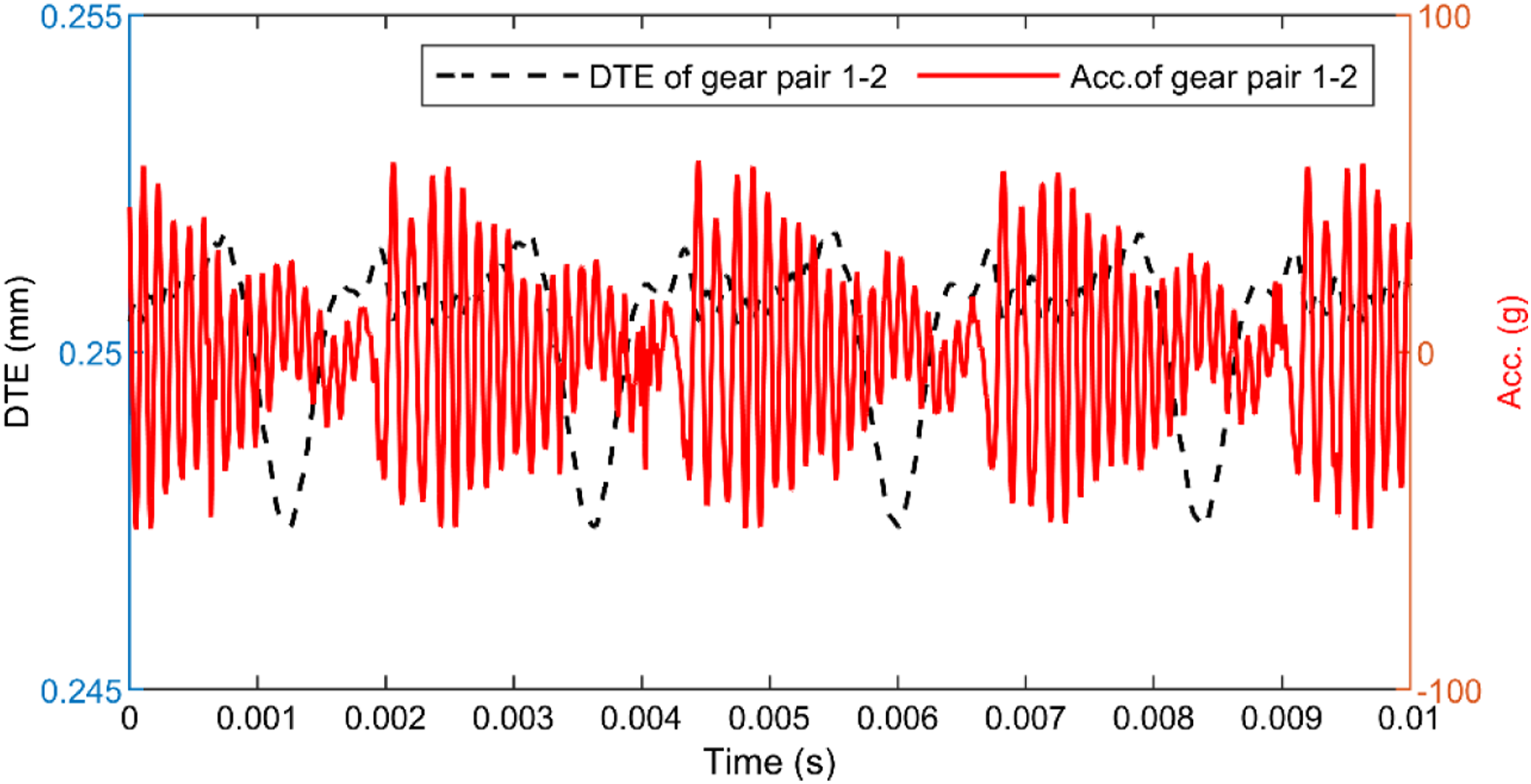
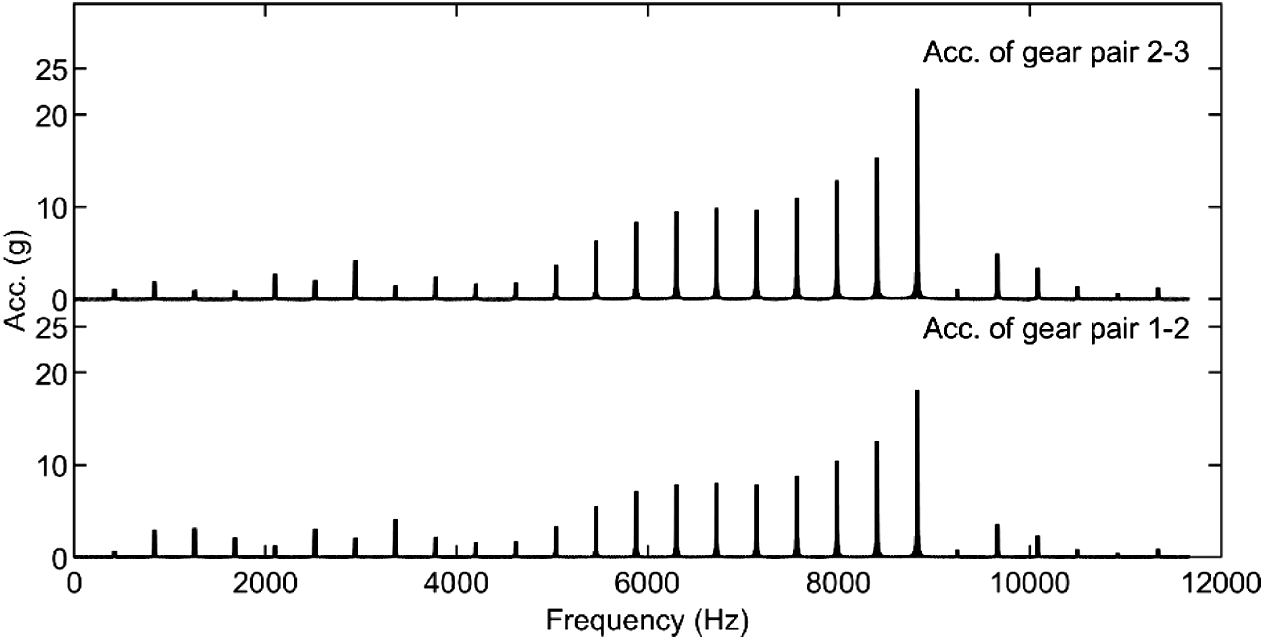
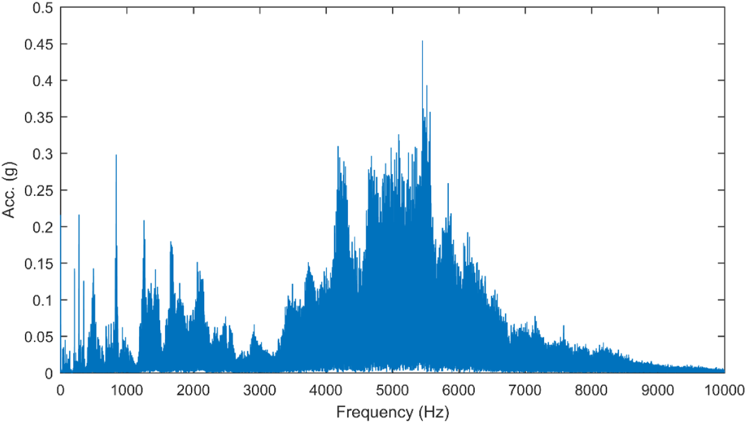
The spectra diagram of the experimental noise pressure and vibration acceleration in X-direction when the input gear works at speed of 700 rpm are illustrated in Figure 8 and Figure 9, respectively. It can be seen that the noise pressure in frequency domain is dominated by the mesh frequency component. Similar to the Acc. responses of the idle gear set, there are many high frequency components in the range of 3000 Hz to 8000 Hz, in the spectrum of the vibration acceleration of the gerotor pump house. Different from the gear transmission acceleration given in Figure 7, the frequency components higher than 8000 Hz are not observed, which might be filtered by the house structure. The cavitation and gear mesh excitation are the main internal sources for the noise and vibration of the gerotor pump. The generation of these high frequency components of pump house vibration acceleration may also be caused by the cavitation behavior. When cavitation takes place, bubbles are created at lower pressure. As the liquid passes from the suction side of the impeller to the delivery side, the bubbles implode. This creates a shockwave that hits the impeller and creates torque fluctuation. The fluctuation frequency is related to the input shaft speed and the teeth of the pump rotor, namely, 1050*z4/60 = 70 Hz. In contrast, the torque fluctuation may induce mechanical vibration subject to gear drive. As shown in Figure 9, the gear mesh harmonic components occur with several lower sidebands at 70 Hz. It is certain that the cavitation exists in this tested pump, which may be the main reason causing the resonant of the structure related to the gear pair improperly meshing vibration modes, and result in the frequency components in 3000 Hz to 8000 Hz in spectrum of vibration acceleration. Spectrum of tested noise pressure at 700 rpm. Spectrum of tested vibration acceleration of gerotor pump at 700 rpm.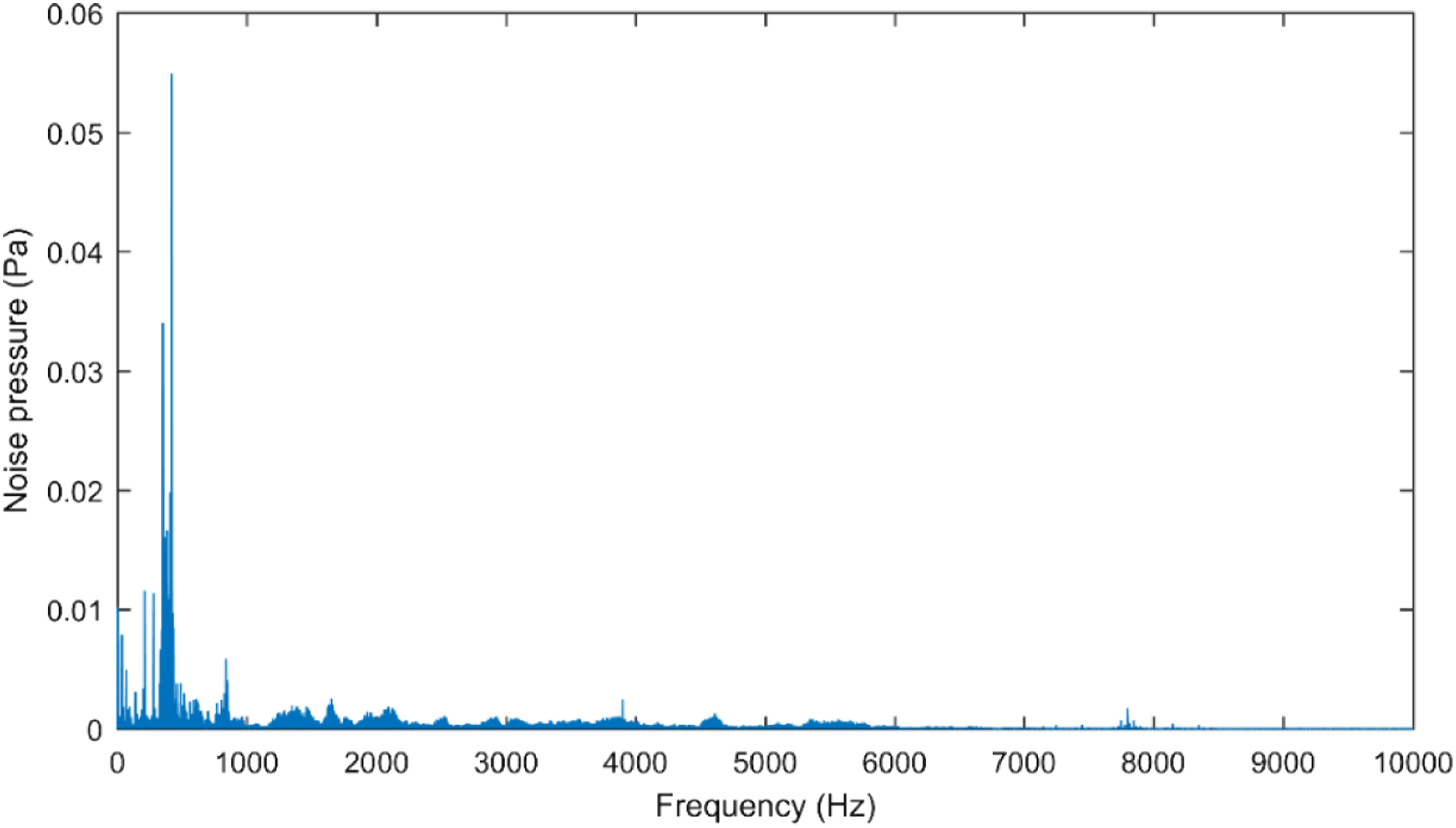
In the second case, our attention will focus on the effect of input shaft speed on the dynamic response of the gerotor pump. As shown in Figure 10, the root mean square value of the Acc. curve increases almost linearly with the increase the input shaft speed. In the below of the figure, the vertical line between 0 and 1 indicates impact, 0 means lose contact and 1 means contact. The single-side impact motion of the drive gear is detected expect for 700 rpm, 800 rpm, and 1000 rpm conditions. It means that the gear drive will undergo impact motion when they operate in higher speed condition. RMS of simulated acceleration with respect to input shaft speed.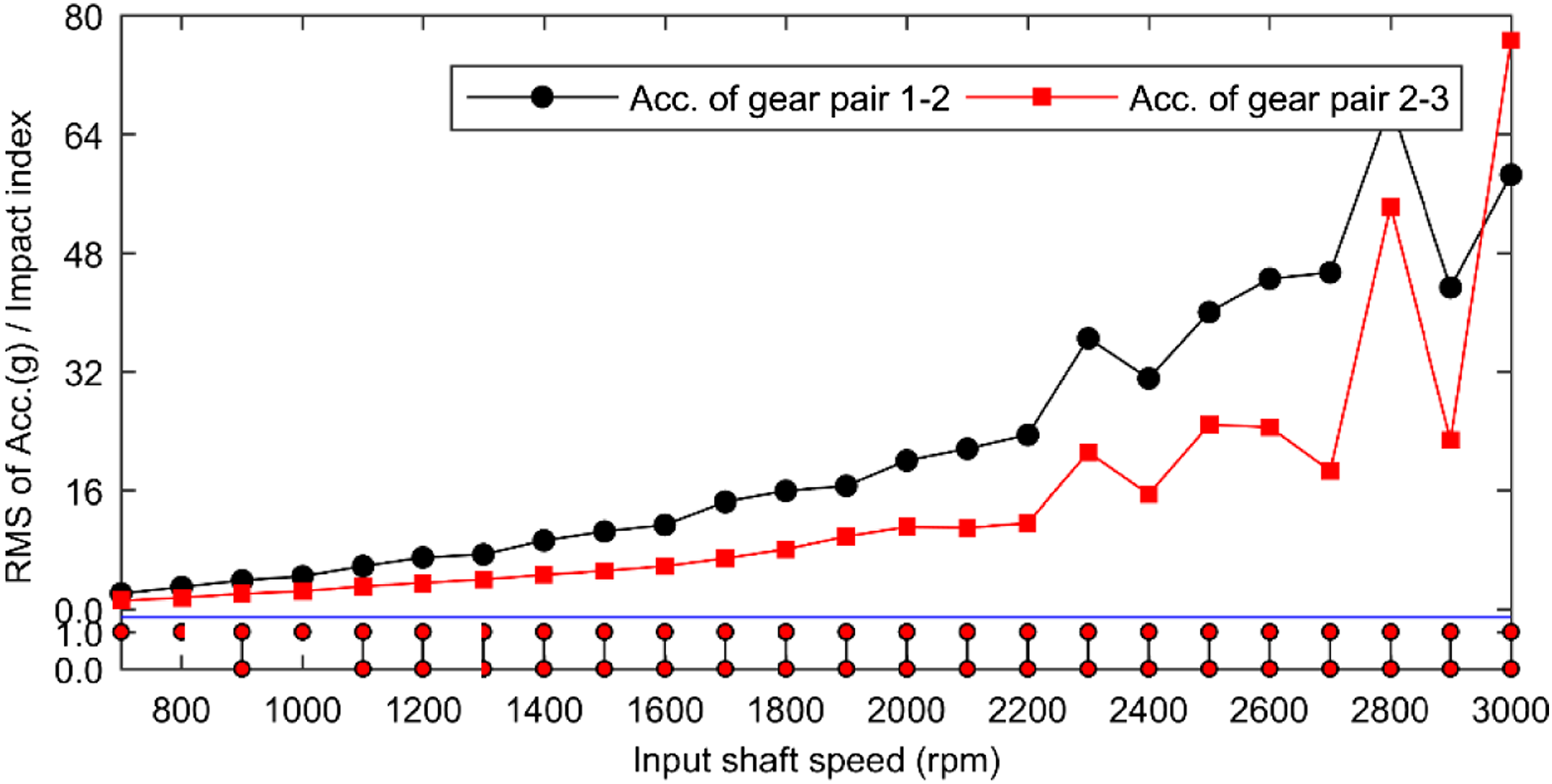
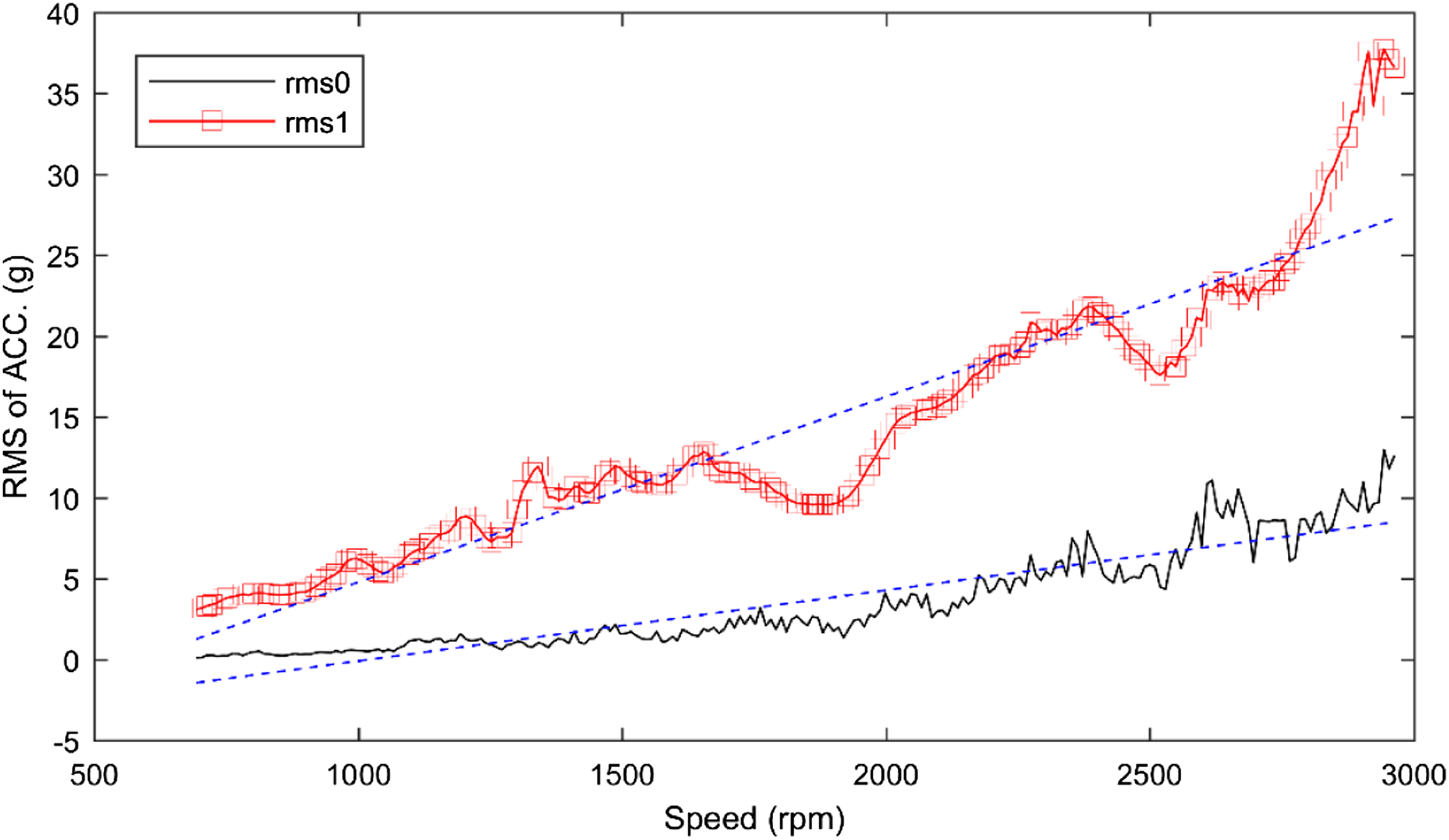
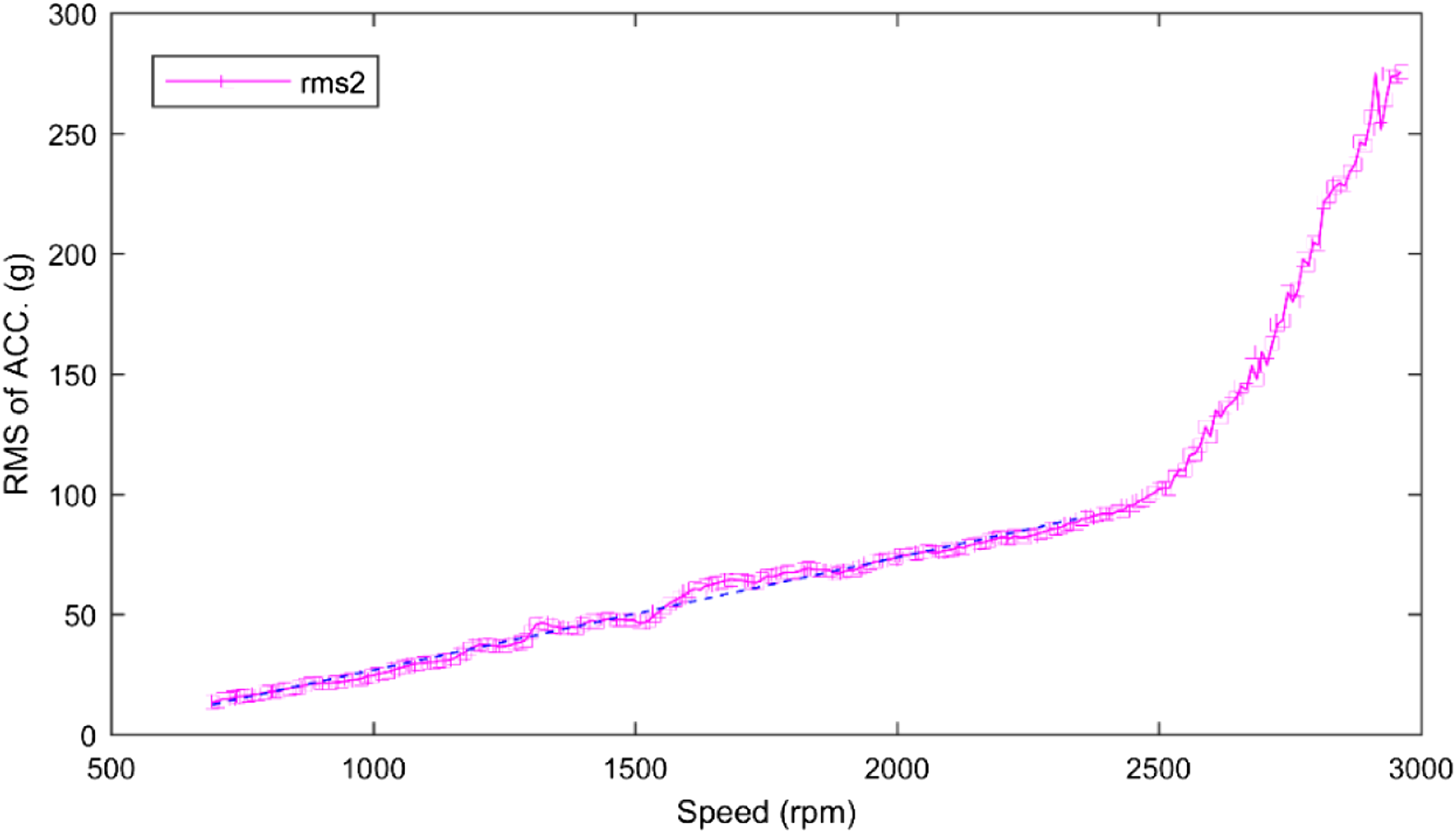
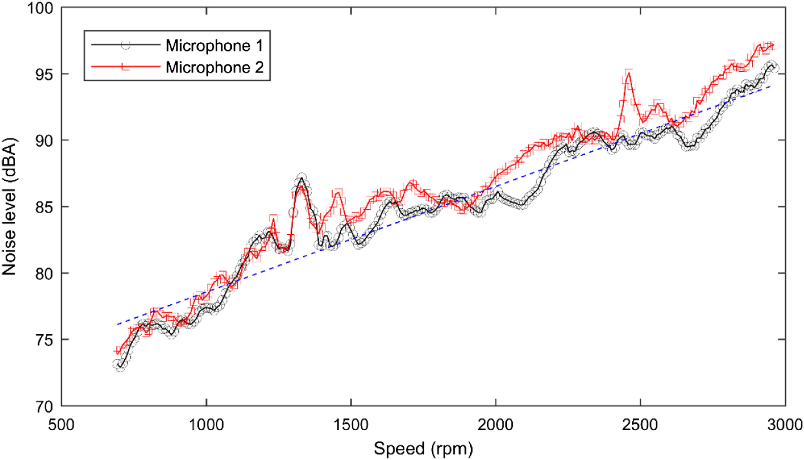
To validate the numerical results, a-weighting noise level is calculated and the root mean square (RMS) is used to deal with the acceleration signal. And the corresponding calculation formula is given in Equation 15. When the speed increases, the higher energy frequency components due to cavitation are almost the same and locate at the range of 3000 Hz to 8000 Hz. Hence, the RMS value of the acceleration response is calculated in the frequency domain where two frequency ranges, namely, lower than 3000 Hz and larger than 3000 Hz, are considered, respectively, to distinguish the effects of mechanical vibration and cavitation. The RMS value of vibration acceleration at mesh frequency harmonics is also calculated to indicate the effect of tooth mating process. As given in Figure 11 and Figure 12, rms0 indicates the filtered RMS value related to mesh harmonic components, and rms1 and rms2 are the RMS values related to the low frequency band (lower than 3000 Hz) and high frequency band (higher than 3000 Hz), respectively. It is observed that both the numerical and experimental results increase when the input shaft speed increases linearly. The effect of input shaft speed on the dynamic response of the gerotor pump is consistent. Figure 13 shows the overall noise level of gerotor pump when the input speed increases from 700 to 3000 rpm. It can be seen from Figure 13 that the overall noise levels of pump in both microphones increase linearly from 73 dBA to 97 dBA. It appears that the noise level is well proportional to the rms1value of acceleration response. It means that the gear transmission system dominates the overall noise level (as shown in Figure 8). Here one should note that the rms0 also increases linearly when the speed increases, but the slopes of the two curves are not similar. This may be due to the sidebands around the mesh frequency. In addition, the effect of cavitation phenomena will be enhanced when the input speed increases, as shown in Figure 12. It can be seen from this figure that when the input speed is lower than 2500 rpm, the energy in the high frequency band increases linearly with respect to the input speed. When the input speed continues to increase, the energy will increase sharply. As concomitant phenomenon, the input speed of the gerotor pump fluctuates greatly in this region. RMS of tested acceleration signals related to mesh frequency and lower frequency components with respect to input speed. RMS of tested acceleration signals related to higher frequency components with respect to input speed. Noise level of the gerotor pump with respect to input speed.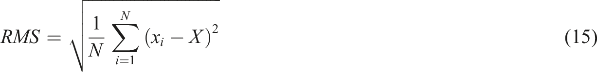
Effect of torque fluctuation
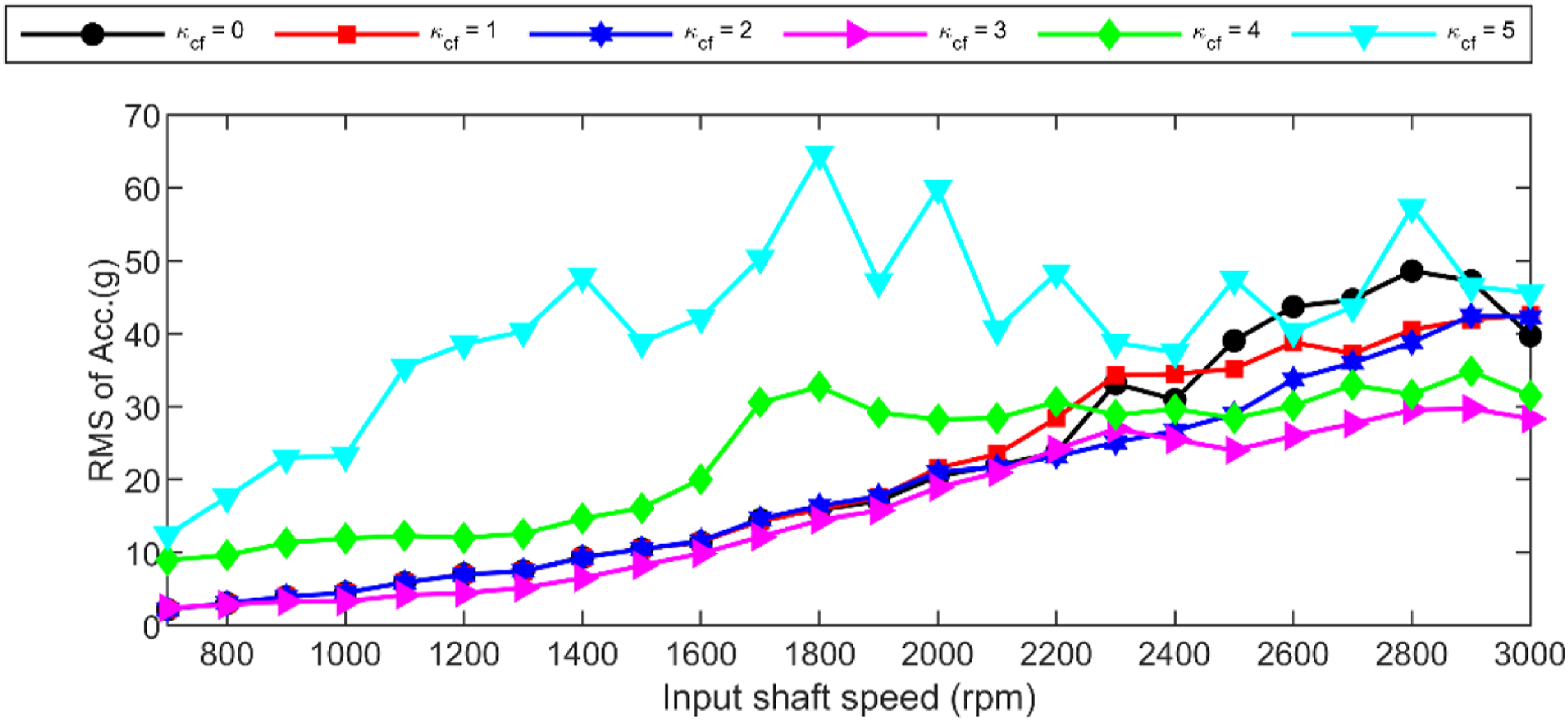
As mentioned in section 2.2, the gerotor pump will undergo unwanted pressure pulsation and result in torque fluctuation. The torque fluctuation can intensify the vibration of the gerotor pump, and the RMS value of the numerical simulated acceleration with different dynamic fluctuation factors is shown in Figure 14. It can be seen that, under the design condition (700 rpm), the difference among the first three cases ( RMS of simulated acceleration with respect to input shaft speed considering torque fluctuation. RMS of simulated acceleration related to mesh frequency with respect to input shaft speed considering torque fluctuation. Spectra of simulated acceleration related to mesh frequency considering torque fluctuation.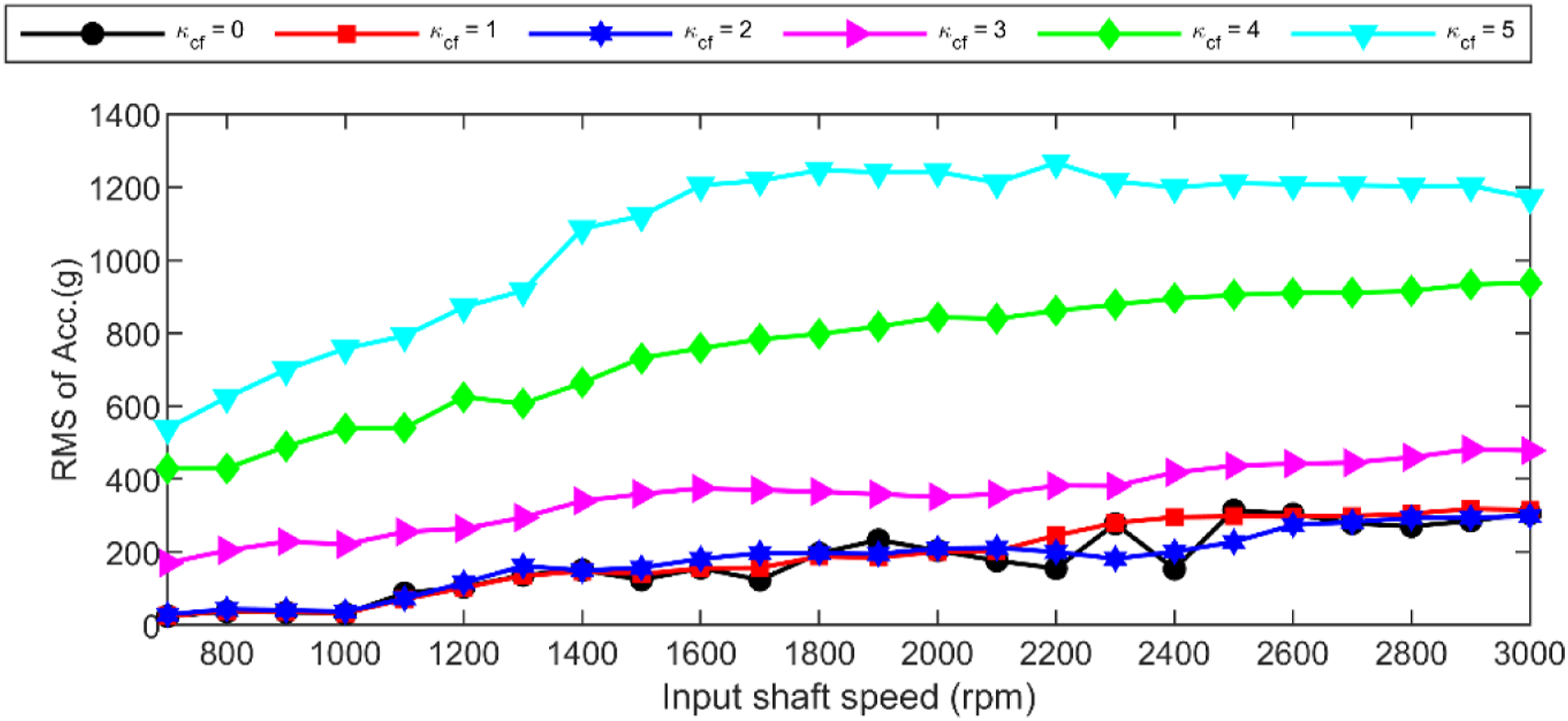
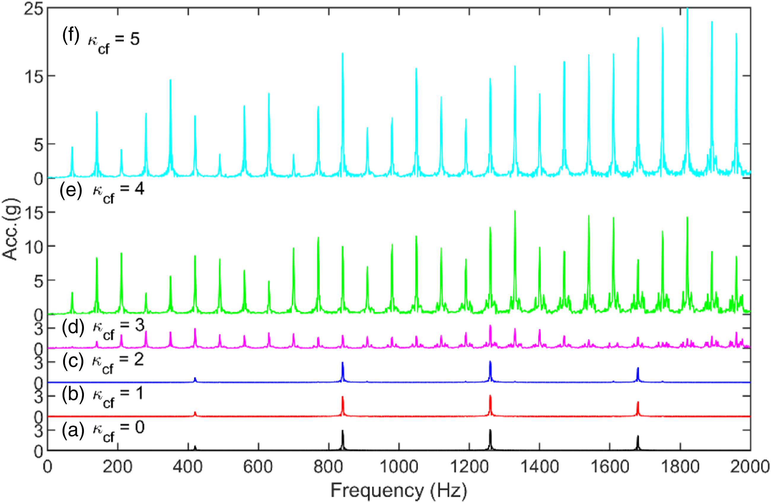
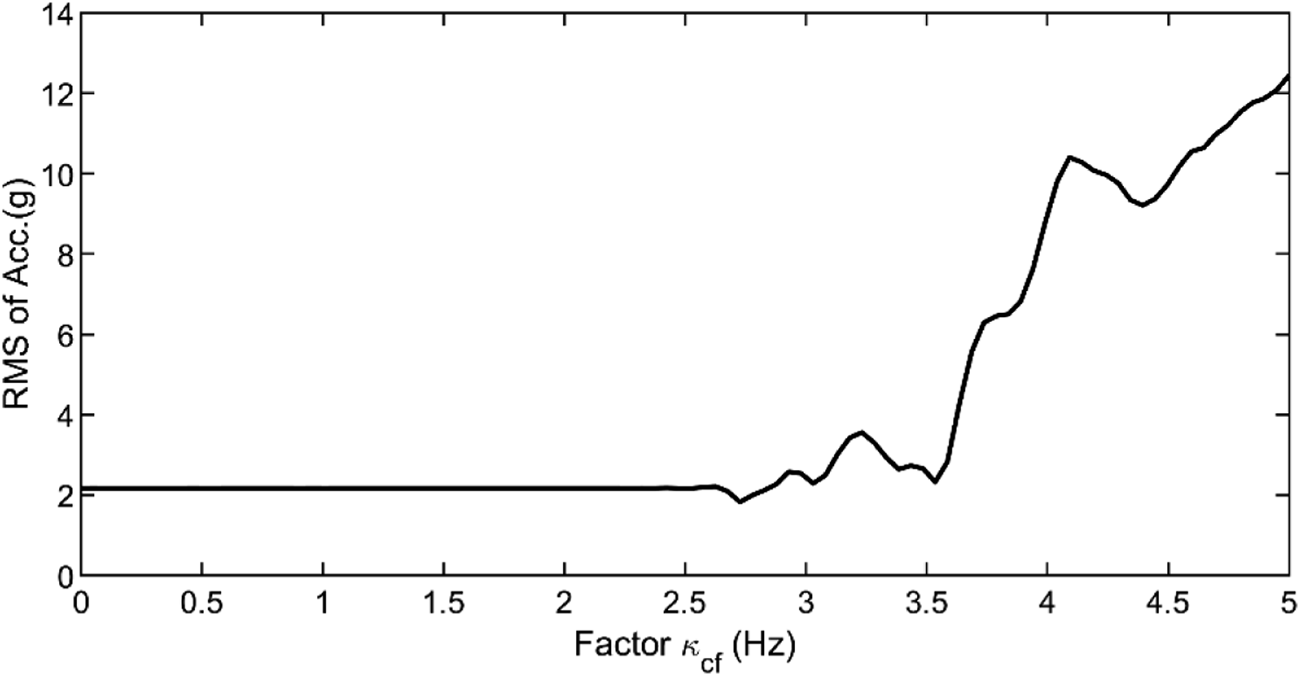
There is still a problem, that is, the critical quantity of the torque fluctuation as an influence factor can cause this serious vibration. Figure 17 and Figure 18 show the overall and filtered about the mesh frequency RMS of the gerotor pump with respect to fluctuation factor RMS of simulated acceleration with respect to torque fluctuation. Filtered RMS of simulated acceleration related to mesh frequency with respect to torque fluctuation.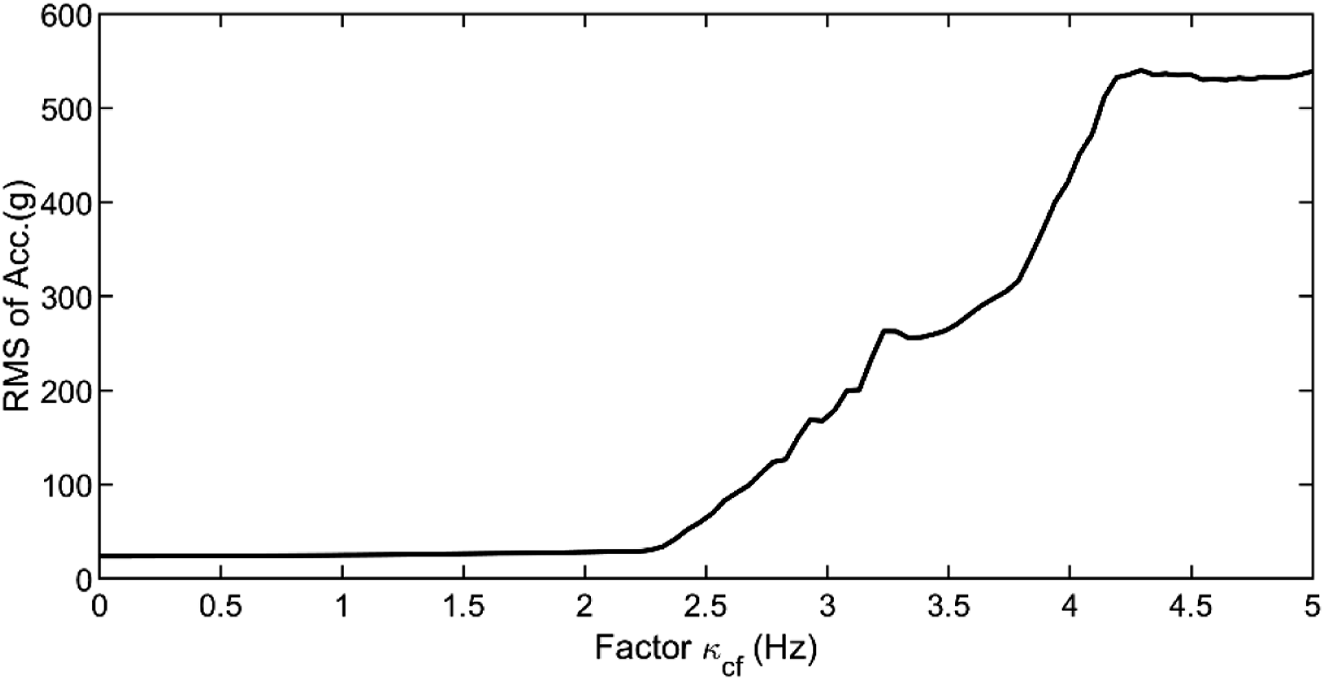
Effect of tooth backlash
Figure 19 shows the coupled effect of tooth backlash and torque fluctuation on the dynamic response. It is observed that when the torque fluctuation factor is smaller than 3, the effect of backlash can be neglected. When the fluctuation factor equals to 3, the overall RMS of the gerotor pump increases with the increase of tooth backlash and a peak is detected around 0.135 mm. There is almost not variation when the backlash is larger than 0.16 mm. The effect of backlash under the condition RMS of acceleration with respect to tooth backlash.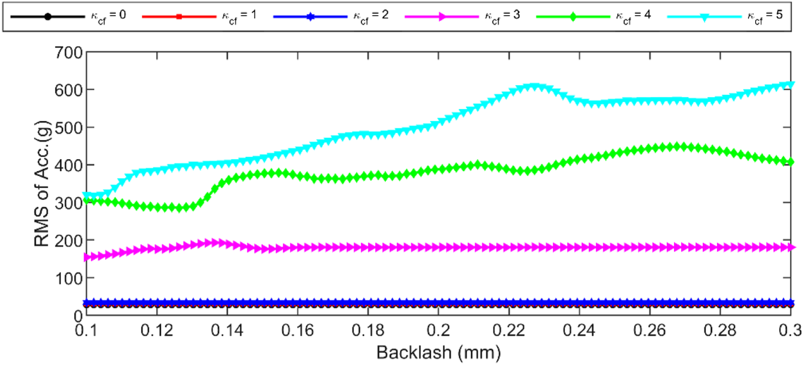
Signal processing and noise source analysis of gerotor pump
Time synchronous averaging method
The time synchronous averaging method is used to process the vibration and noise signals and improve the signal-to-noise ratio, especially in the application of gear transmission, bearing, and rotating machine. With this method, after enough averaging times, signal asynchronous with shaft rotation including random noises can be eliminated from the measured signal leaving only the signal appearing at the harmonic orders of shaft rotations.
As described in the sections 2 and 3, the vibration and tachometer signals of gerotor pump are simultaneously sampled at the same rate. The input speed may fluctuate more or less in practice. Hence, we can transfer the time-domain signal to angle-domain signal using the tachometer reference signal to reduce the effect of speed fluctuation. Then the synchronous averaging process can be modeled as,
Noise source analysis
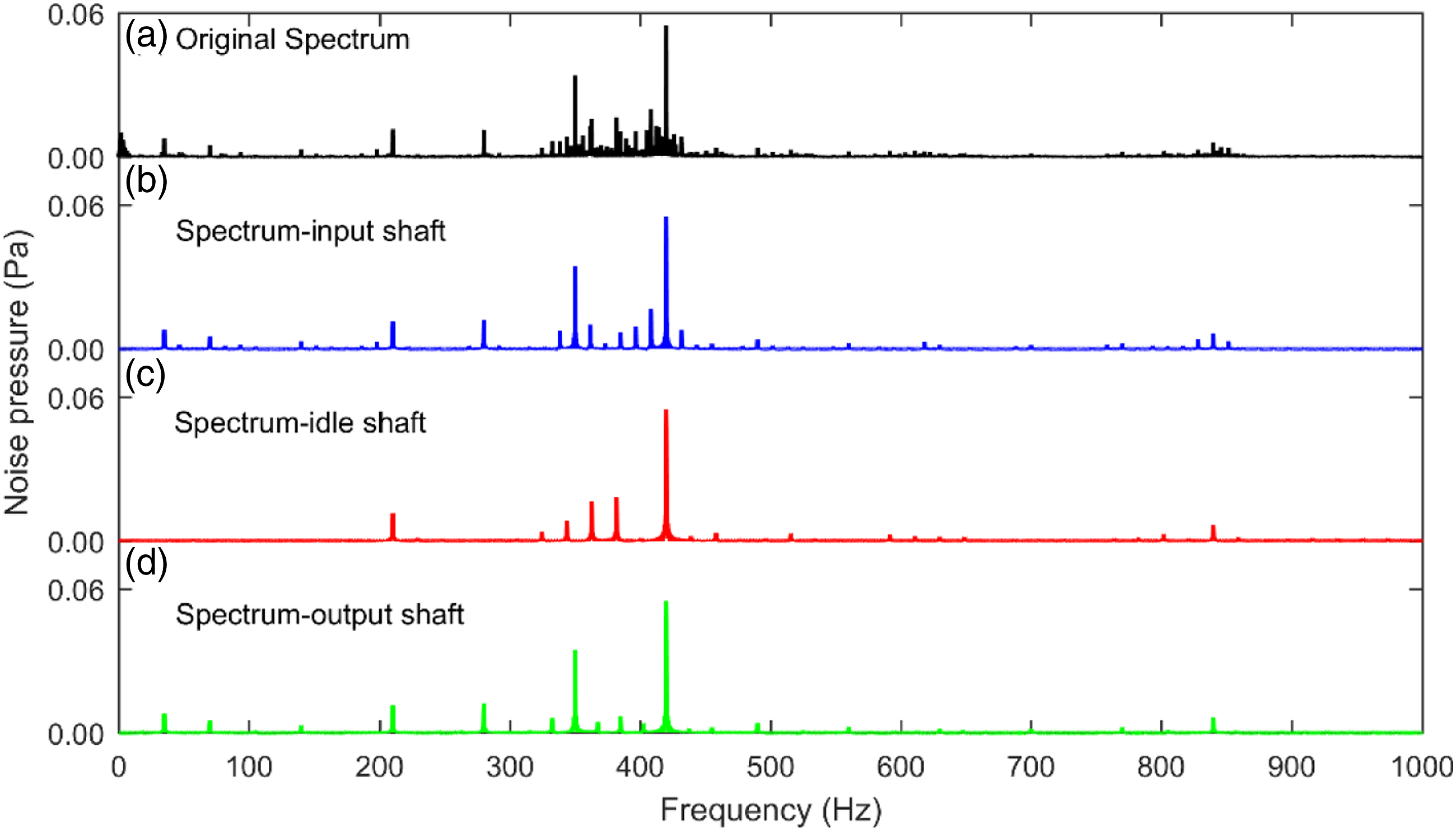
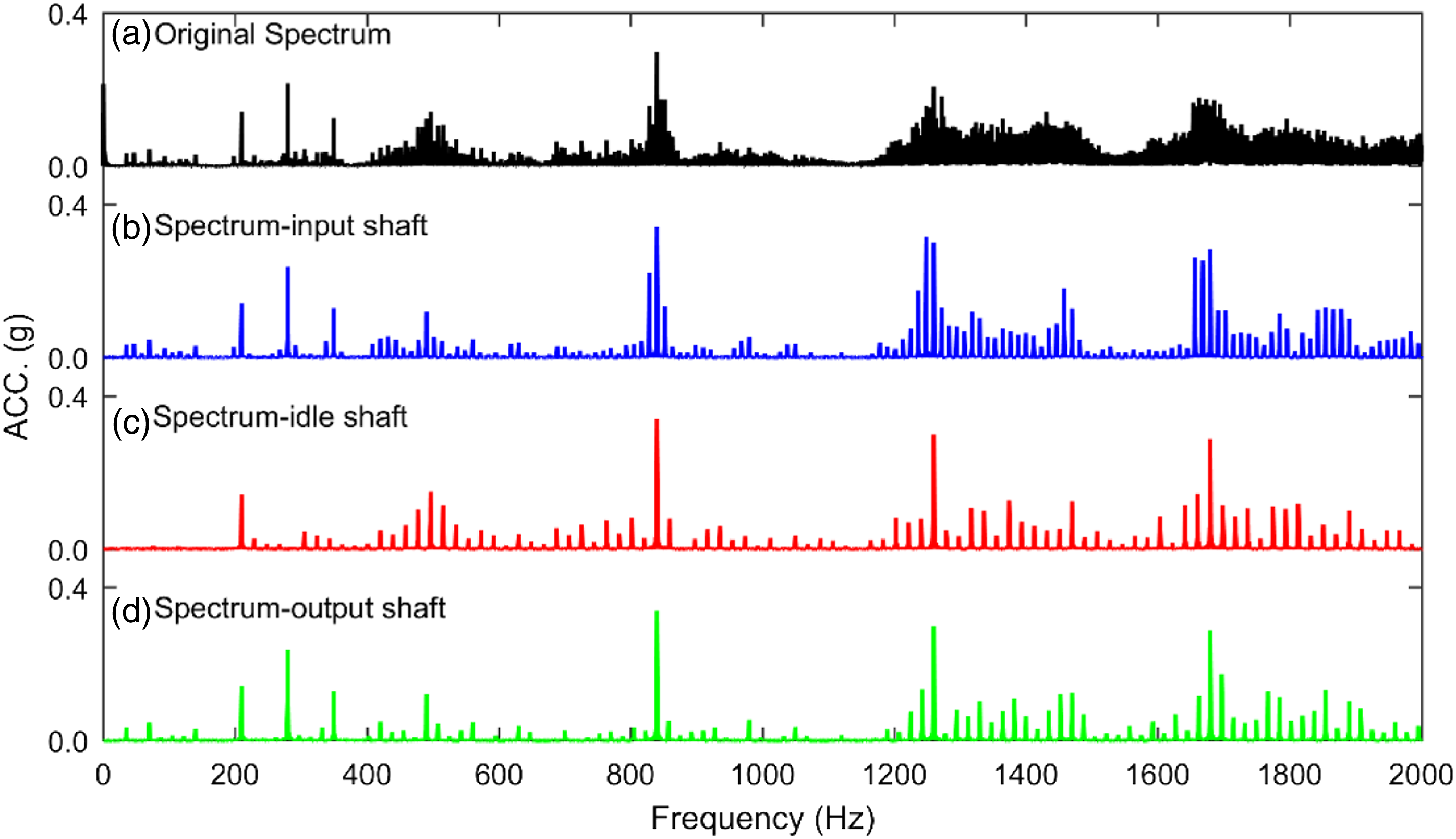
In this subsection, we firstly process the noise pressure signal obtained from the gerotor pump test rig at 700 rpm. The time synchronous averaging (TSA) method is adopted to each gear shaft. Figure 20 shows the single shaft waveforms for the input shaft, idle shaft, and output shaft, respectively. In this figure, only one revolution is shown; however, the corresponding time period is different due to different rotation speeds of shafts. Obviously, the averaged signals are modulated with certain low frequency components. Figure 21 shows the spectrum of the original noise pressure signal and spectra related to the waveforms in Figure 20. Only the frequency range below 1000 Hz is shown as the amplitude in the high frequency range is very small. In this range (below 1000 Hz), the lower orders of shaft harmonics and the first two mesh frequencies are covered. It can be seen that the mesh frequency component (420 Hz) is identical; however, the lower sidebands are different for the three averaged signals. Single shaft time synchronous averaging noise waveforms with respect to input shaft, idle shaft, and output shaft. Spectra of the (a) original noise data, (b) TSA data of input shaft, (c) TSA data of idle shaft, and (d) TSA data of output shaft.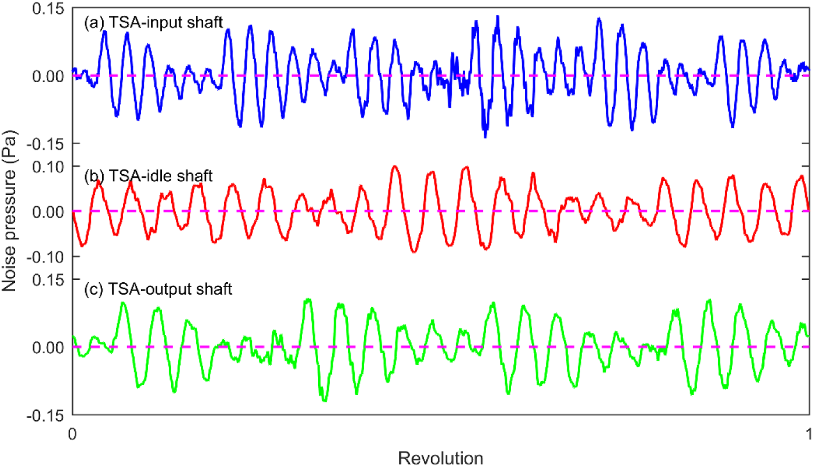
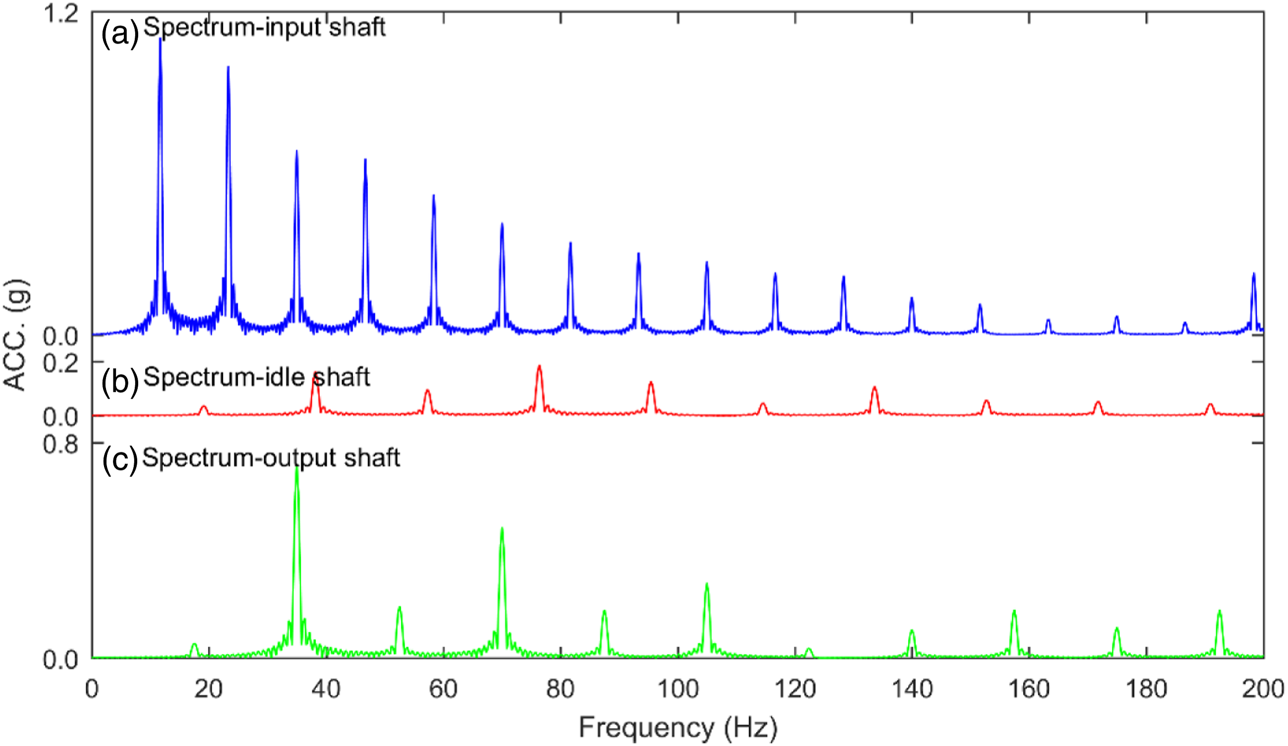
To distinguish the sideband and/or the modulation, the Hilbert transform can be adopted and the spectra of their envelopes are shown in Figure 22. From Figure 22, it can be seen that the input and output shaft frequency modulations will enlarge the amplitude of 70 Hz component. As a result of this effect, there are many 70 Hz sidebands such as 210 Hz, 280 Hz, and 350 Hz are found in the original noise signal. Envelope spectra of the averaged noise signals.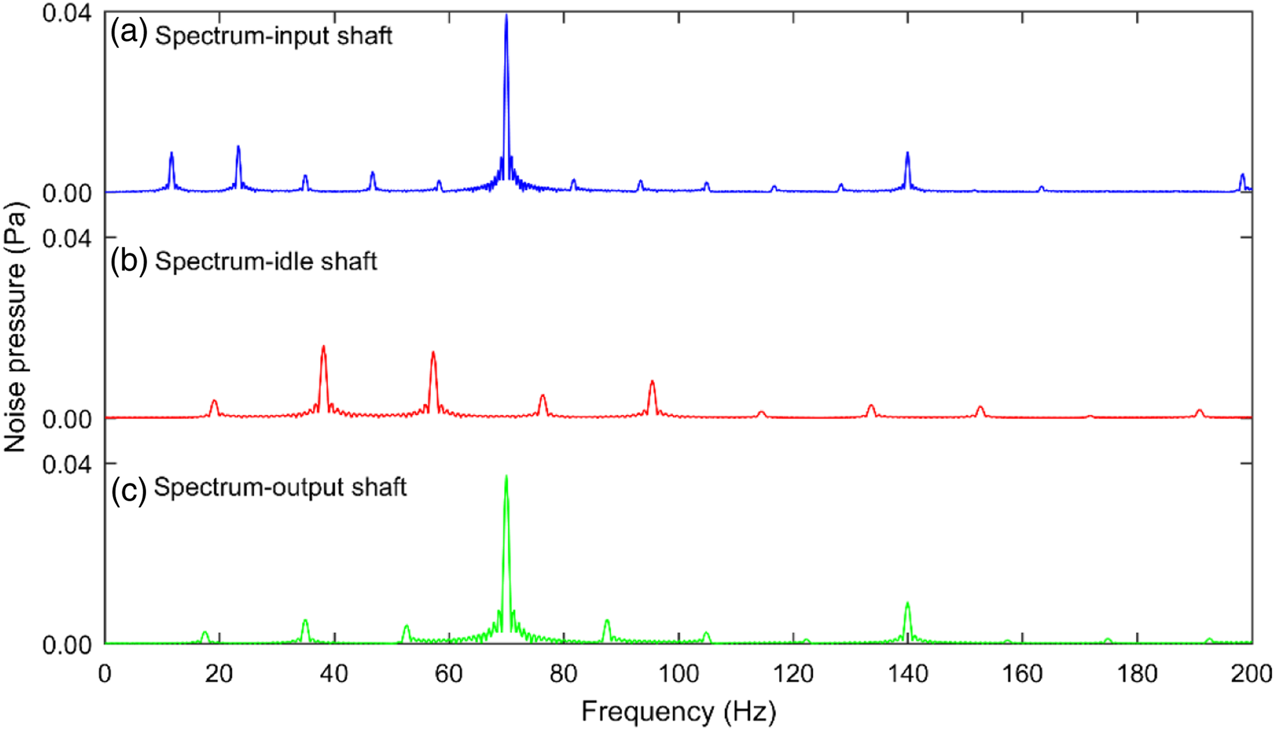
In order to better understand the noise source of gerotor pump, the simultaneously sampled vibration signals are also processed. In contrast, the single shaft vibration waveforms, their spectra, and the spectra of envelope of the averaged vibration signals are shown in Figure 23, Figure 24, and Figure 25, respectively. It can be seen from Figure 23 that a burst occurs once each revolution in the time synchronous averaging vibration waveform of the input shaft. In the spectrum, vibration modulation and many sidebands are detected around the second and the higher mesh harmonic components as shown in Figures 24 and 25. This phenomenon may be related to eccentricity or localized gear faults. As the localized gear faults can also introduce sidebands in spectrum, but there is not found after re-examination of gear pair. Furthermore, the burst phenomena are only detected in the averaged vibration waveform of the input shaft. It means that this phenomenon is only related to input shaft and caused by eccentricity of input shaft or input gear. Take a glance at the mesh frequency harmonics, one can find that the amplitude of the first mesh harmonic is very small, and the second and third mesh harmonics are large evidently. It indicates that the gear transmission system appears backlash impact. Hence, the mechanical vibration of the gerotor pump in the low frequency range is mainly induced by the gear tooth impact. Single shaft time synchronous averaging vibration waveforms with respect to input shaft, idle shaft, and output shaft. Spectra of the (a) original vibration data, (b) TSA data of input shaft, (c) TSA data of idle shaft, and (d) TSA data of output shaft. Envelope spectra of the averaged vibration signals.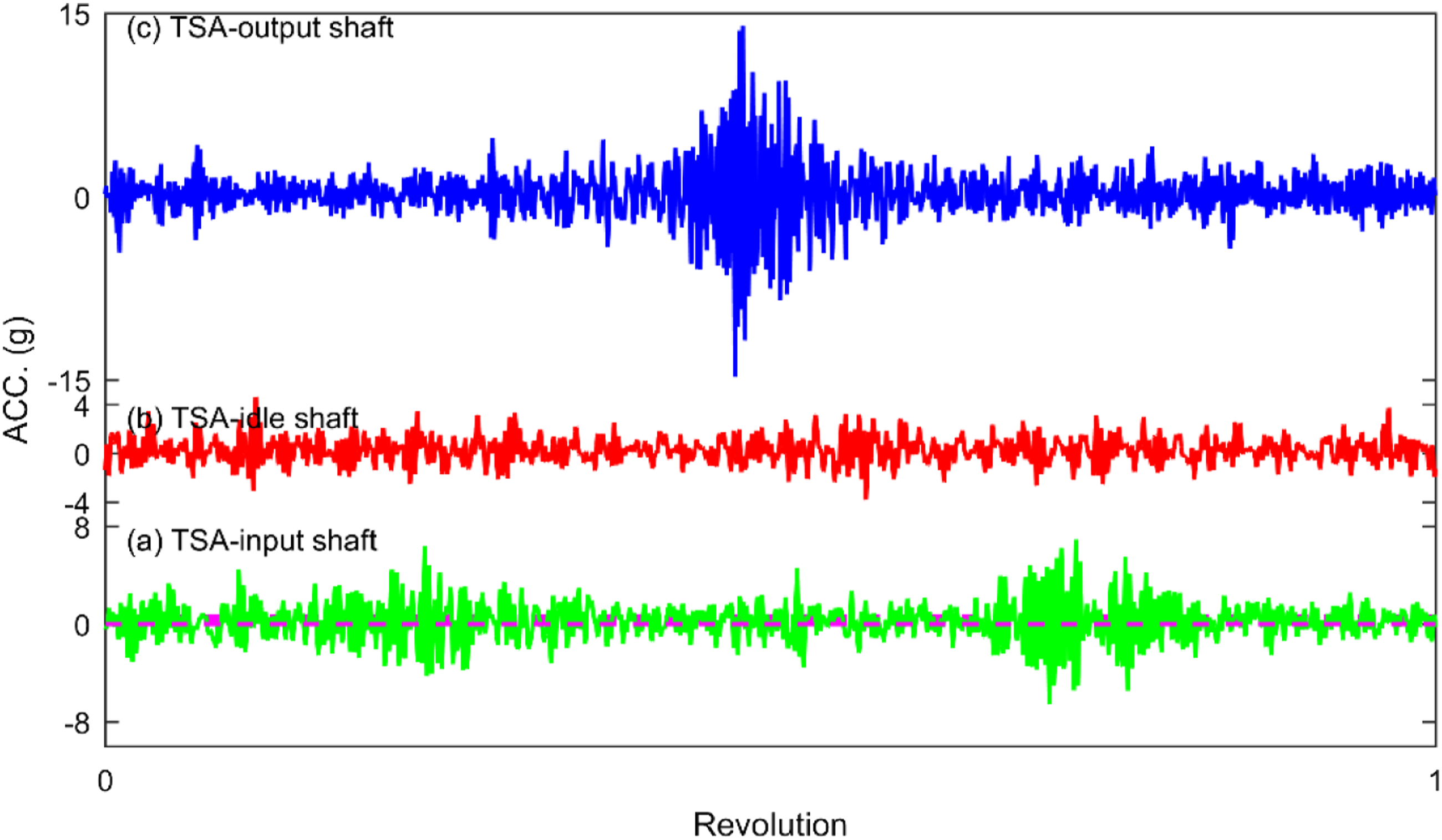
Conclusions
In this study, a dynamic model considering time-varying mesh stiffness and backlash was proposed to investigate the vibration behavior of the idle gear set in a gerotor pump. A test rig for the gerotor pump was also built and experiments were performed in different work condition including certain input speed case and ramp speed case. The effects of input shaft speed, torque fluctuation due to cavitation, and gear tooth backlash on the dynamic performance of gerotor pump were analyzed based on the numerical simulation results and the experimental measured signal. Several conclusions are listed as follows: (1) The dynamic transmission error of drive gear in the gerotor pump is dominated by the first three mesh harmonic components when the torque fluctuation is neglected. In the vibration acceleration response, many high order components are detected, which might be caused by the high frequency ripple fluctuation of time-varying mesh stiffness and the cavitation behavior of the pump. When designing gear pumps, it is necessary to consider the effect of cavitation on vibration response (2) The RMS values of both the numerical and experimental vibration acceleration of gerotor pump increase almost linearly with the increase of input shaft speed. The noise level is well proportional to the rms1value of acceleration response. In addition, the effect of cavitation phenomena will be enhanced when the input speed increases. (3) When the torque fluctuation is considered, the dynamic responses of gerotor pump are modulated by the torque fluctuation. The modulation or sidebands are found firstly in the high frequency band under design condition. With high level torque fluctuation, the vibration of drive gear will be dominated by frequency components related to pump rotor and much more vibration energy will concentrate on the high frequency band. (4) When the torque fluctuation factor is smaller than 3, the influence of backlash on the vibration acceleration can be neglected. When the fluctuation factor is larger than 3, the RMS values of the gerotor pump vibration acceleration increase with the enlargement of tooth backlash. The effect of tooth backlash on the dynamic performance of gerotor pump is limited and mostly depended on the torque fluctuation condition. (5) The gerotor pump noise is dominated by the low frequency component around the mesh frequency. The vibration energy can be divided into two parts in the frequency domain. In the low frequency band, the vibration energy is caused by the mechanical vibration. However, in the high frequency band, the cavitation phenomena may cause the concentration of the vibration energy and resonant of pump structure. The cavitation will induce the fluctuation of the drag torque of the gerotor pump system. The result shows that the eccentric feature related to the input shaft is detected and the vibration of the gerotor pump is strongly modulated by the input shaft frequency. The gear set driving the pump occurs backlash impact as the higher amplitudes of the second mesh harmonic is detected.
Footnotes
Declaration of conflicting interests
The authors declare no potential conflicts of interest with respect to research, authorship, and/or publication of this article.
Funding
The author(s) disclosed receipt of the following financial support for the research, authorship, and/or publication of this article: This work was supported by the National Natural Science Foundation of China (NSFC) through Grant No. 52005515. The authors also gratefully acknowledge the supports of the Project of State Key Laboratory of Precision Manufacturing for Extreme Service Performance, Central South University, through Grant No. ZZYJKT2021-06, the Hunan Provincial Natural Science Foundation of China through Grant No. 2023JJ20066 and No. 2021JJ40740, the Changsha Natural Science Foundation Project No. kq2202096 and the Postgraduate Scientific Research Innovation Project of Hunan Province (Grant No. 150110048).