
Abstract
Free-play-induced nonlinear dynamic behavior has been one of the most important topics of aeroelastic research in recent decades. In this paper, the describing function (DF) method is developed to investigate the complex dynamic response of a popular all-movable horizontal tail with free-play. Piecewise expressions for the time history and phase portrait of limit cycle oscillation (LCO) are derived by the developed DF method, which is conducive to understand the mechanism of free-play-induced LCO. Another advantage of the developed DF method is the ability to predict the high-order harmonics, which cannot be realized by the classic DF method. A three-dimensional (3D) all-movable horizontal tail model with torsional free-play was designed and manufactured to implement wind tunnel tests via various initial parameters. A good agreement was found between the numerical and experimental results, which can demonstrate the effectiveness of the proposed method. The influence of the initial parameters of the all-movable horizontal tail on the LCO characteristics is analyzed by both numerical calculations and wind tunnel tests. The method and results in this paper can provide a significant reference for the design of all-movable horizontal tail versus the free-play-induced LCO.
Keywords
Introduction
Flight tests, wind tunnel tests, and analytical studies have demonstrated that aeroelastic system with structural nonlinearity may exhibit various complex dynamic behaviors, such as bifurcation, chaos, high-order harmonics, and limit cycle oscillation (LCO).1–4 Such nonlinearity can bring great impacts on handling quality, ride quality, and structural fatigue life.5–8 Free-play has been recognized as a non-negligible inducement of these problems, because it is the most significant source of structural nonlinearity.9–12
Various methods have been developed to study nonlinear aeroelastic behaviors induced by free-play. Among them, the harmonic balance (HB) method and its variants are practical tools for predicting and analyzing nonlinear dynamic responses and have been widely applied to aeroelastic systems with free-play nonlinearity in the past decades.13,14 When only the first harmonic is considered, the HB method is usually called describing function (DF) method. Verstraelen et al. 15 investigated a simple aeroelastic system with pitch free-play and employed the DF method to predict the amplitude and frequency of LCO. The calculated results were compared with measurements from wind tunnel test, and the co-existence of two-domain and three-domain LCOs was proved. Yang et al. 16 also used this DF method to investigate the LCO behaviors of an aeroelastic airfoil with free-play at different Mach numbers. The results suggested that the LCO behaviors present variable characteristics in different Mach number ranges. It is found that the DF method has been widely used due to its efficient estimation on the amplitude and frequency of LCO, but it fails to predict high-order harmonics. 17 A higher-order harmonic balance (HOHB) method was employed by Liu and Dowell 18 to investigate the high-order harmonics response versus free-play nonlinearity of a two-dimensional airfoil with control surface. Fichera and Ricci 19 applied the HOHB method to a T-tail model with control surface free-play, and the calculated results were verified by wind tunnel tests. Compared with the DF method, the HOHB method improves the prediction accuracy; however, its expressions will become more and more complicated as the number of harmonics increases. 20 Dimitriadis 21 applied the high-dimensional harmonic balance (HDHB) method to a transport aircraft model with control surface free-play. The results showed that the HDHB method can predict the bifurcation behavior induced by free-play accurately. However, Liu et al. 20 demonstrated that the HDHB method requires 2n harmonics to achieve similar accuracy to the HOHB method with n harmonics. In addition, Dimitriadis 22 proposed a numerical continuation method to predict the bifurcation behavior of a transport aircraft with free-play nonlinearity. Numerical continuation method provides an efficient approach to bifurcation analysis, on the other hand, it is neither easily applicable to high degrees-of-freedom systems nor to quantitative analysis. 17 Moreover, Tang and Dowell23,24 developed a computational code for aeroelastic analysis using a linear three-dimensional time-domain vortex lattice aerodynamic model. The flutter and LCO responses induced by horizontal tail free-play were investigated by the computational code and verified by wind tunnel tests of a three-dimensional (3D) model. The general laws and mechanisms of the influence of initial parameters such as free-play angle, flow velocity, and angle of attack on the LCO behaviors were proposed and summarized. With the improvement of computing power, numerical integration methods such as time integration method, 25 Hénon’s technique,26,27 precise integration method,28,29 and computational fluid dynamics technique 30 have been widely used in the solution of nonlinear systems with free-play. The main advantages of numerical integration methods are high accuracy and chaos analysis, 31 however, such methods may be time-consuming for the system with complex structures.32,33
The existing methods should be developed versus quick assessment on the aeroelastic behaviors induced by free-play, especially complex aircraft structures are included in the nonlinear system. 34 Based on such intention, a developed method is expected as: (1) it is able to predict high-order harmonics; (2) it can reflect the mechanism of free-play-induced LCO; (3) it is free from iteration and initial guess on dynamic response; and (4) it has low computational cost for complex structure. Besides, previous studies on free-play-induced LCO mostly focused on two-dimensional airfoil models, and studies on the influence of free-play nonlinearity on 3D models are further needed.35–37 Therefore, one convenient method which can be efficiently applied to any 3D model with complex structures, and can be verified experimentally is demanded.
In this paper, a developed DF method is proposed to predict the aeroelastic behaviors induced by free-play quickly. Free-play generally exists in all-movable horizontal tail system due to inevitable gear clearances, loose bearings, and worn hinges. Therefore, a 3D all-movable horizontal tail model is designed to verify the developed DF method and investigate the effect of free-play on aeroelastic response. In the section on the developed describing function method, the equations for estimating the time history and phase portrait of LCO are derived by the proposed developed DF method. In the section on model and method, an experimental all-movable horizontal tail model with torsional free-play device is designed and manufactured. In the section on results and discussion, the numerical results are discussed with the experimental results, and the effect of initial parameters on LCO behaviors is presented. Finally, the key findings and conclusions are summarized in the section on conclusions.
The developed describing function method
In the present work, the DF method is developed to propose an effective way to predict the free-play-induced nonlinear aeroelastic behaviors. This specific solution process is shown in Figure 1. Process of the developed DF method.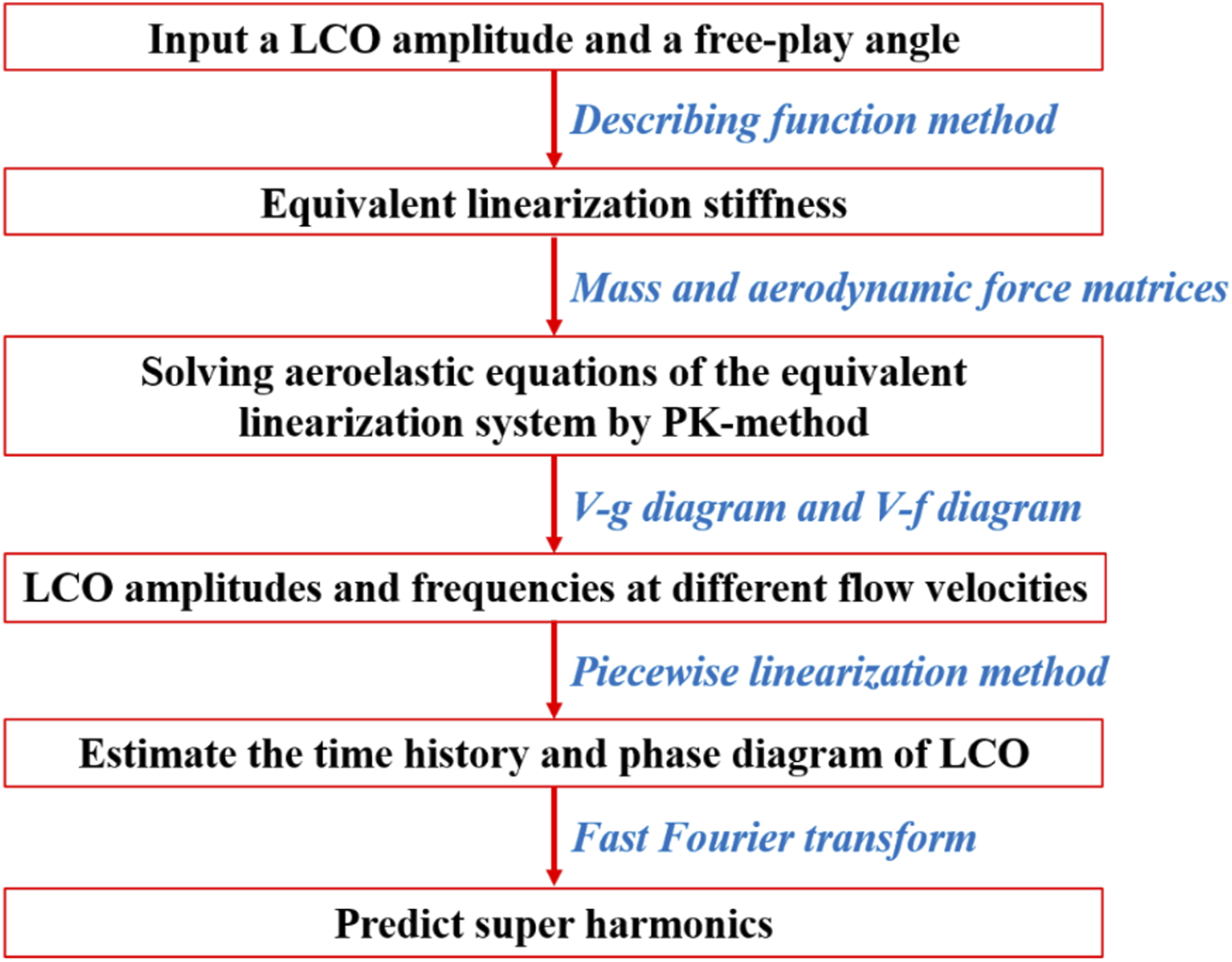
If free-play nonlinearity was included in an aeroelastic system, the related restoring moment-angular displacement curve can be shown in Figure 2. Here: A and δ denote the amplitude and free-play angle, respectively; d = −δ and d = δ are the lower and upper boundaries of the symmetric free-play, which divide the nonlinear system into three piecewise linear subsystems; and k
0
is the stiffness of stiffness region. Symmetric free-play stiffness curve.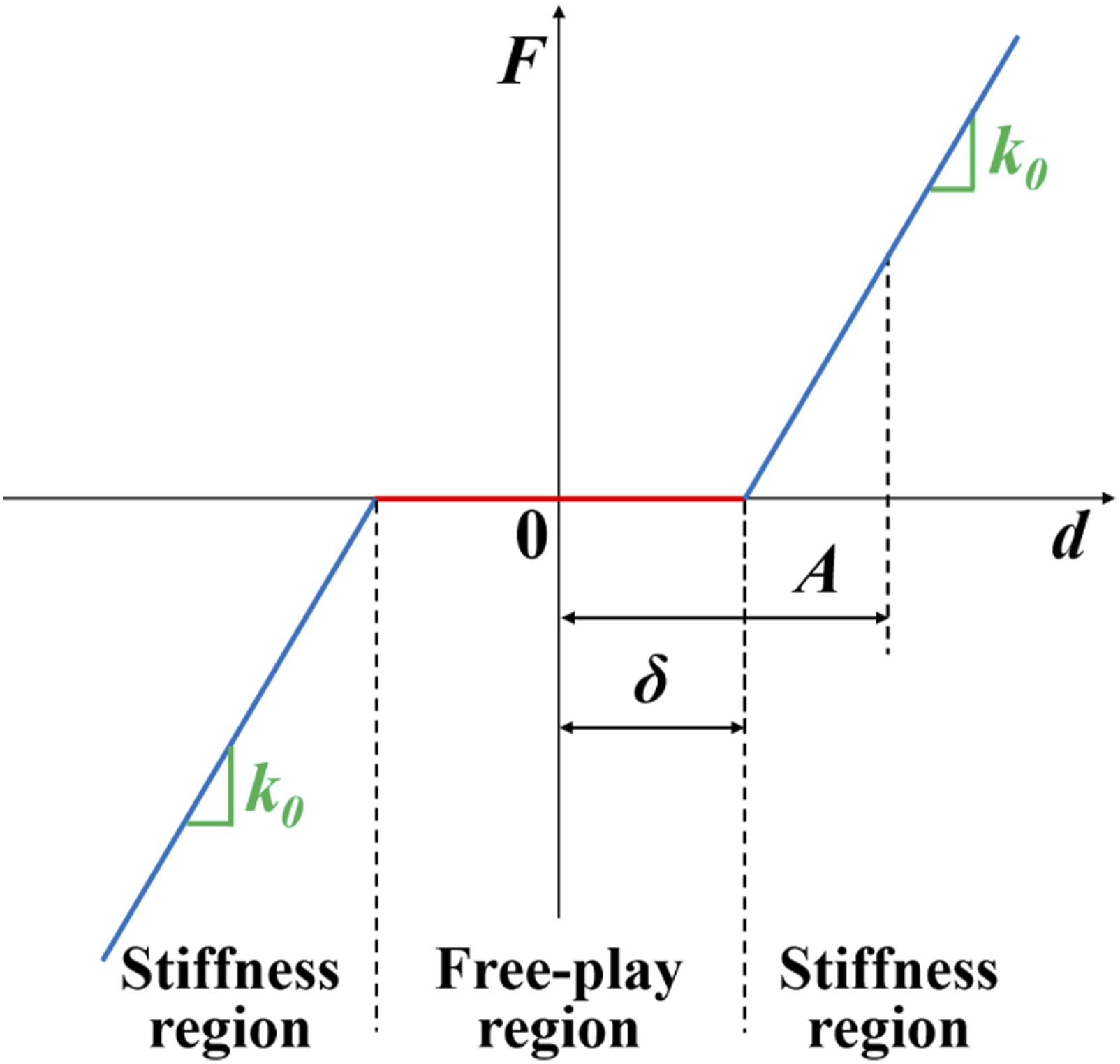
Free-play is described by a piecewise linear function between an input d and an output F

The equivalent linearization stiffness k
eq
has been derived in some existing works,14,38 and here it is written as
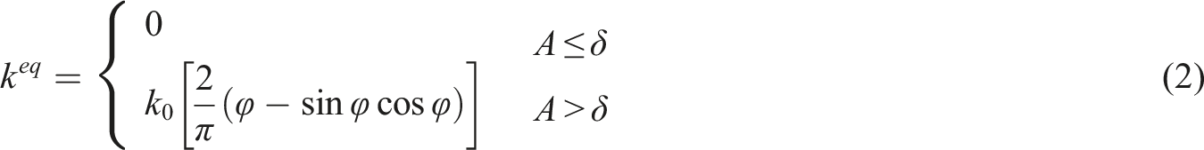
It can be seen that k
eq
is a constant for each given LCO amplitude and torsional gap angle. Therefore, the nonlinear system with free-play can be simplified to an equivalent linearized system. In this paper, an all-movable horizontal tail with torsional free-play is constructed, and its schematic is shown in Figure 3. The elastic support of the model is provided by two leaf-springs, by which the bending and torsional motions are controlled. A torsional free-play exists at the connection between the model and the torsional leaf-spring. Schematic of the present all-movable horizontal tail model with torsional free-play.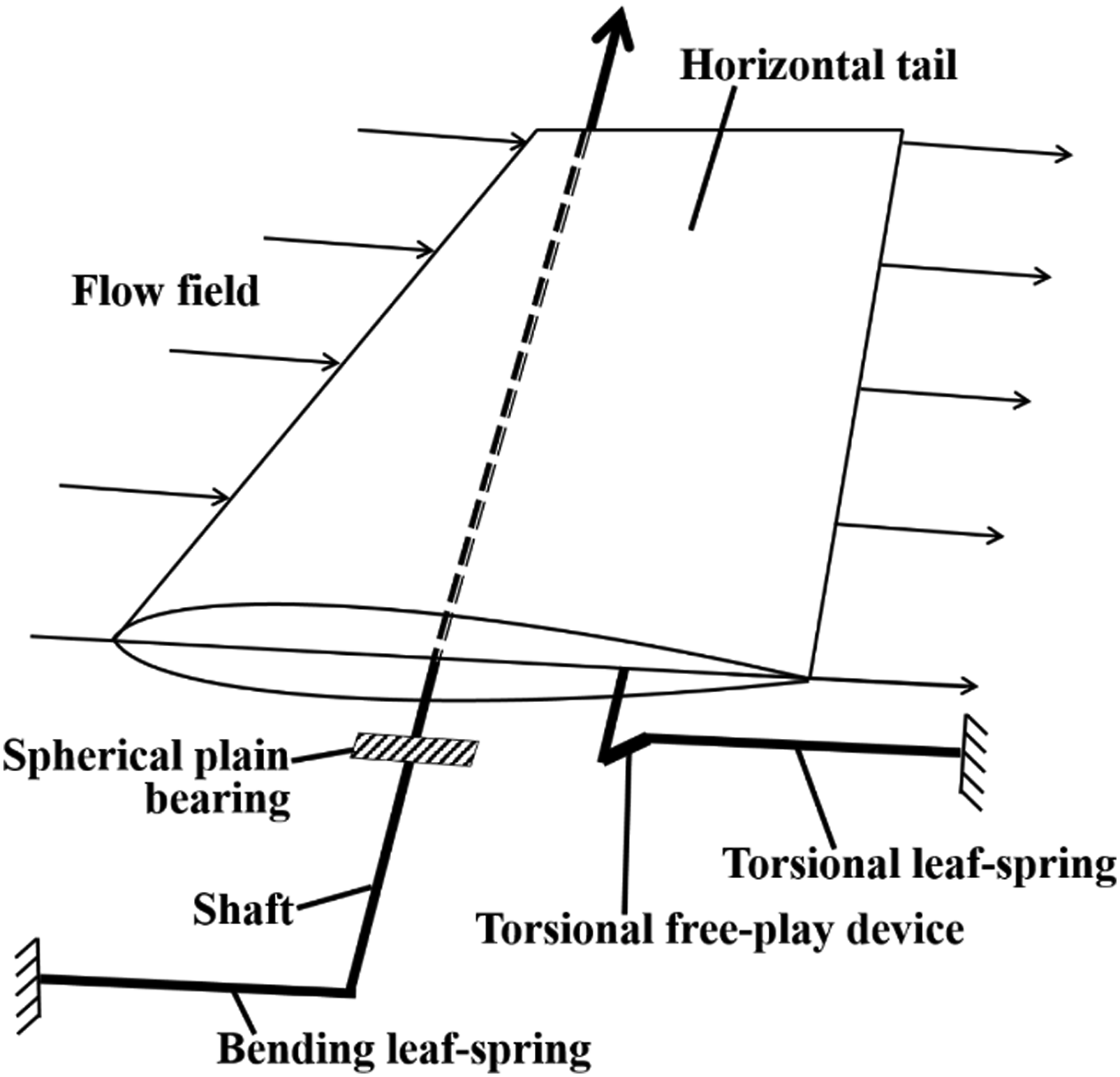
The aeroelastic system can be considered as a complete conservative system when external disturbances and energy losses are not considered. The governing equations of the equivalent linearization system can be written as


Here k can be written as

By substituting equation (4) into equation (3)

Equation (6) can be solved by the PK-method,
39
equation of motion


Then, the reduced frequency k can be written as

The fundamental equation for modal flutter analysis by the PK-method is

Equation (10) is rewritten in the state-space form with twice the order

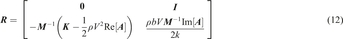
Therefore, solving the flutter equation can be transformed to find the eigenvalues of the real matrix
The time history of torsional angle, which includes free-play region and stiffness region is shown in Figure 4 (i.e., torsional angle amplitude is A, and torsional free-play angle is δ). The time history of torsional angle.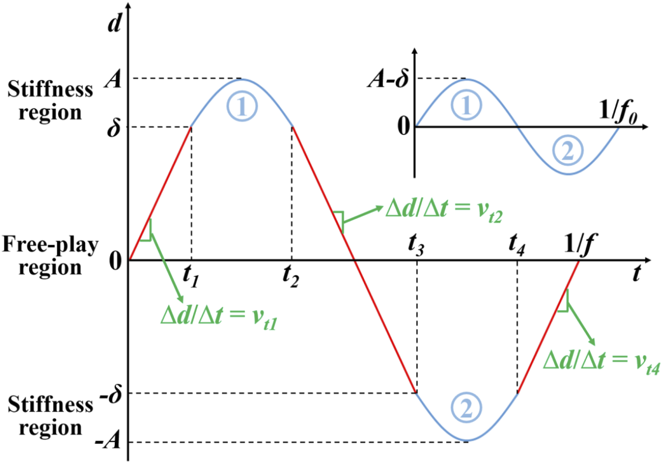
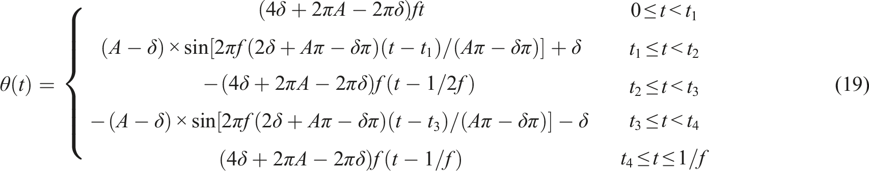
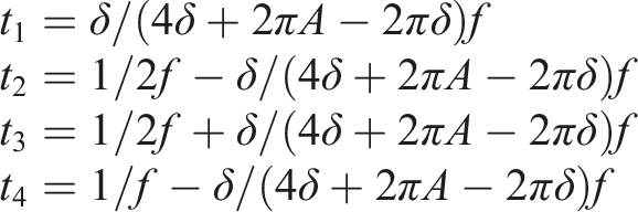
In the free-play region, the potential energy of the torsional spring is zero, and the torsional velocity is constant when the aerodynamic force is not included. The combination of two stiffness regions (i.e., blue lines in Figure 4) can be approximately considered as a simple harmonic oscillation of linear system without free-play. The amplitude of simple harmonic oscillation is A-δ, and the frequency is temporarily set as f0. Then, the functions of torsional displacement (θ) and time (t) can be expressed as


Then


Based on the calculated time history, the high-order harmonics can be predicted quickly by the fast Fourier transform (FFT).
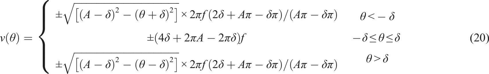
Similarly, the phase portrait of torsional angle and torsional velocity is shown in Figure 5, and it can be expressed as The phase portrait of torsional angle and torsional velocity.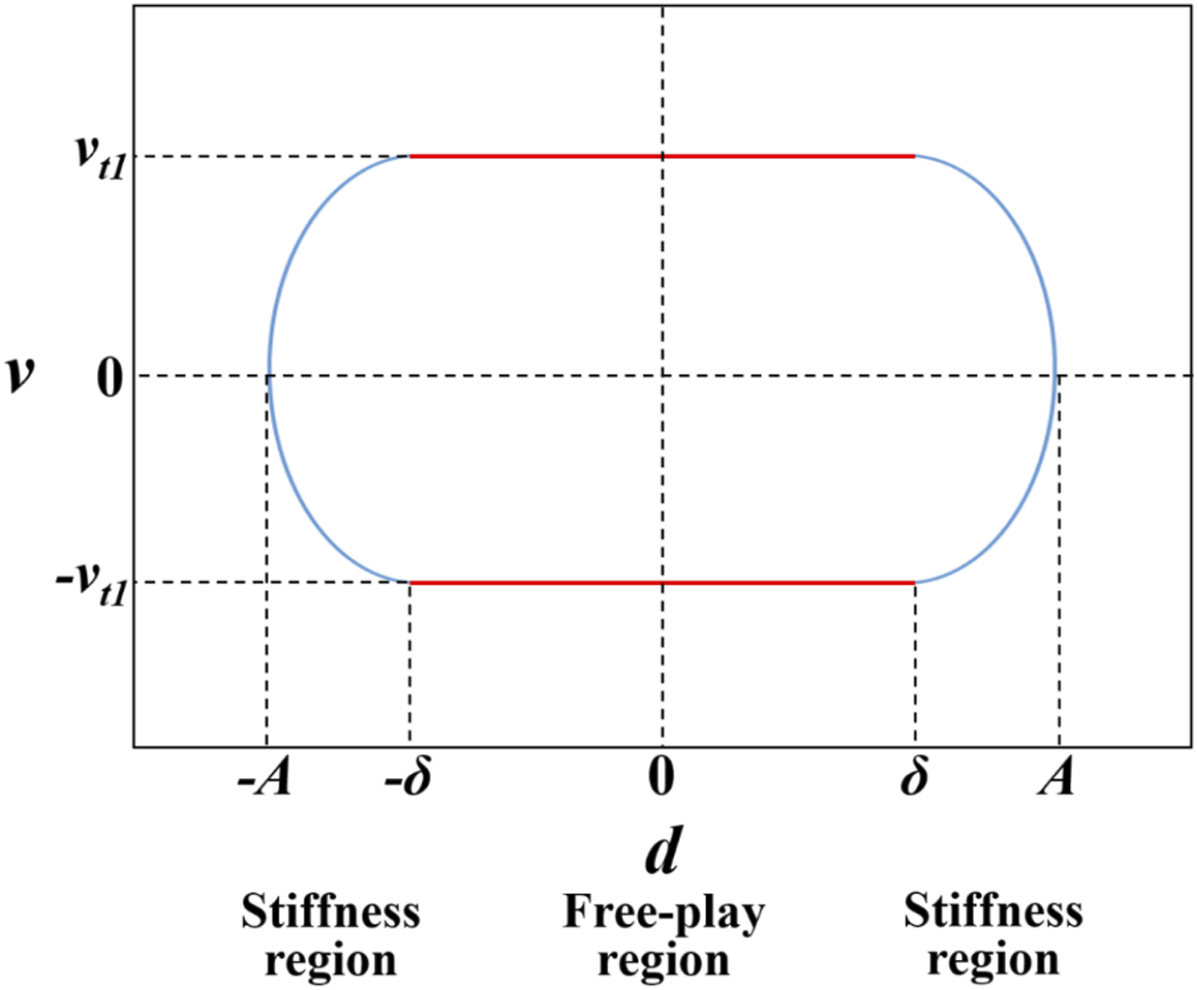
Model and method
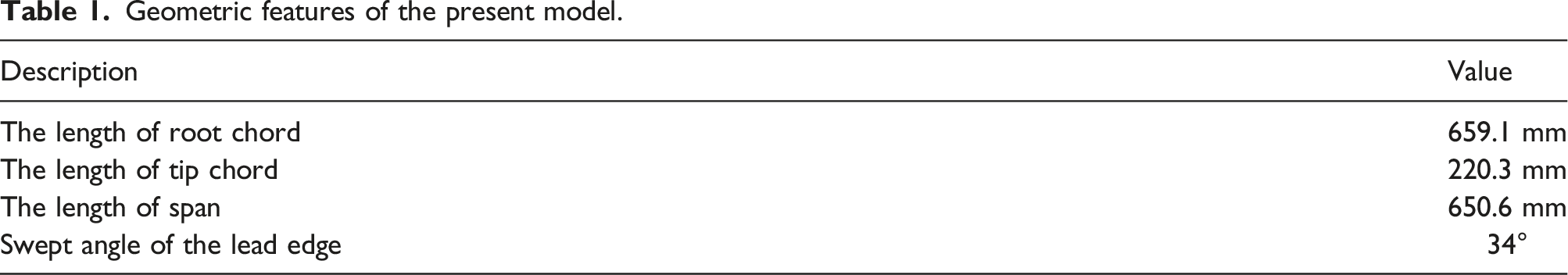
Geometric features of the present model.
Finite element model
A finite element model is established to obtain the mass and stiffness matrices of the horizontal tail, as shown in Figure 6. The equivalent linearized stiffness is achieved by multiplying the elastic modulus of the torsional leaf-spring by the equivalent stiffness factor. The aerodynamic influence coefficient matrix is calculated by the Doublet-Lattice method.
42
Thus, equation (12) can be solved directly by the finite element method (FEM), and the time history and phase portrait can be obtained by equations (19) and (20). Therefore, the present developed DF method can be applied to any complex 3D model easily and efficiently combined with FEM. The finite element model of the all-movable horizontal tail.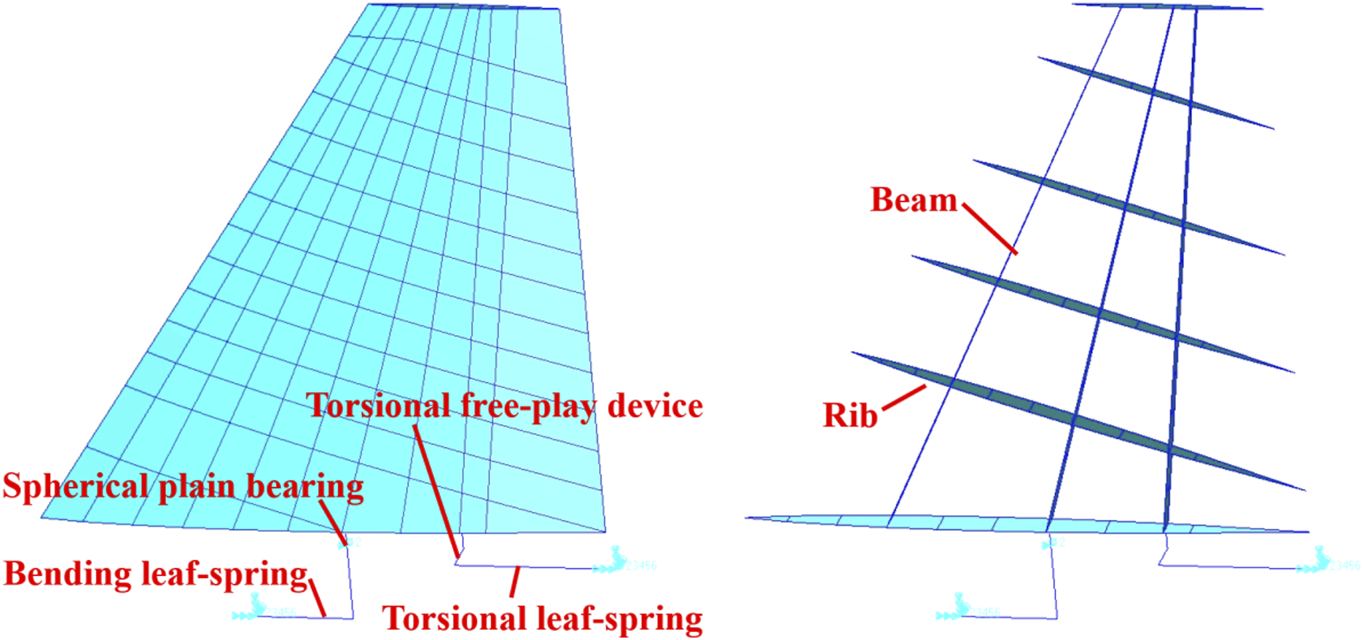
The experimental model with variable torsional free-play
Materials of the components.
The experimental all-movable horizontal tail model.
Details of torsional free-play device are illustrated in Figure 8. The diameter of the intermediate part of torsional free-play pin is smaller than the inner diameter of connector A to achieve a clearance fit. Simultaneously, the torsional free-play pin fits tightly with the connector B through two screws. Therefore, the torsional free-play angle can be adjusted by changing the diameter of the intermediate part of torsional free-play pin.
40
The torsional free-play device.
Free-play measurement
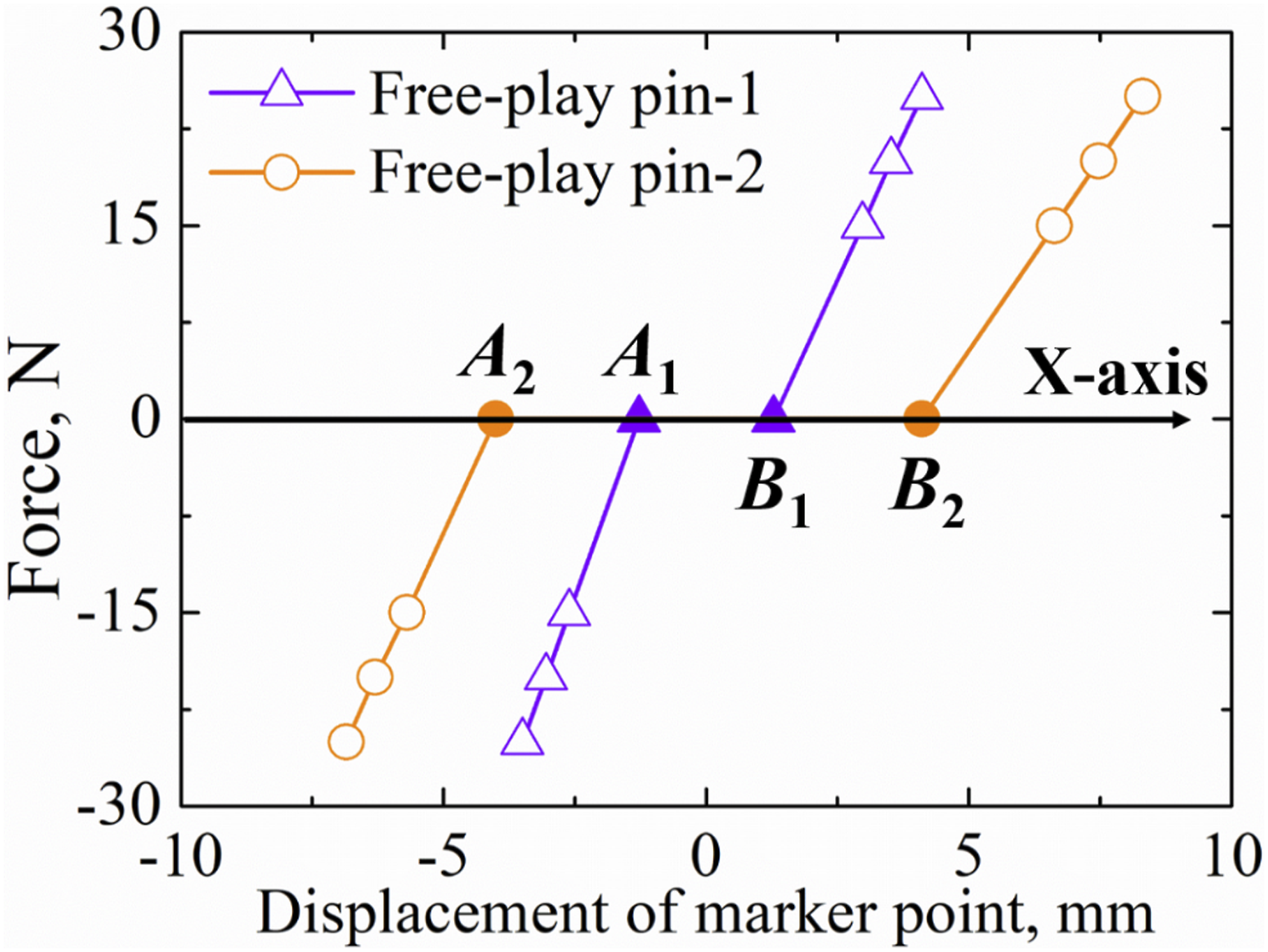
In this work, two torsional free-play pins with different intermediate part diameters were manufactured. The measurement method of the torsional free-play angle is illustrated in Figure 9. The loading point is set at the beam of the horizontal tail, and the marker point is set at the root of trailing edge. For each torsional free-play pin, a group of pulls were applied on both sides of the loading point. Displacements of the marker point under these pulls were measured by a binocular vision measurement system. Measurement of the torsional free-play angle.
Two sets of measurements of marker point are shown in Figure 10. For the ith torsional free-play pin, the intersections of the measured force-displacement curve and the X-axis are calculated by the least square method, denoted by A
i
and B
i
. The interval between A
i
and B
i
represents the free range-of-motion of the horizontal tail caused by torsional free-play when the pull is zero.
40
Here X
Ai
and X
Bi
are used as the X-axis coordinates of A
i
and B
i
(X
Bi
> X
Ai
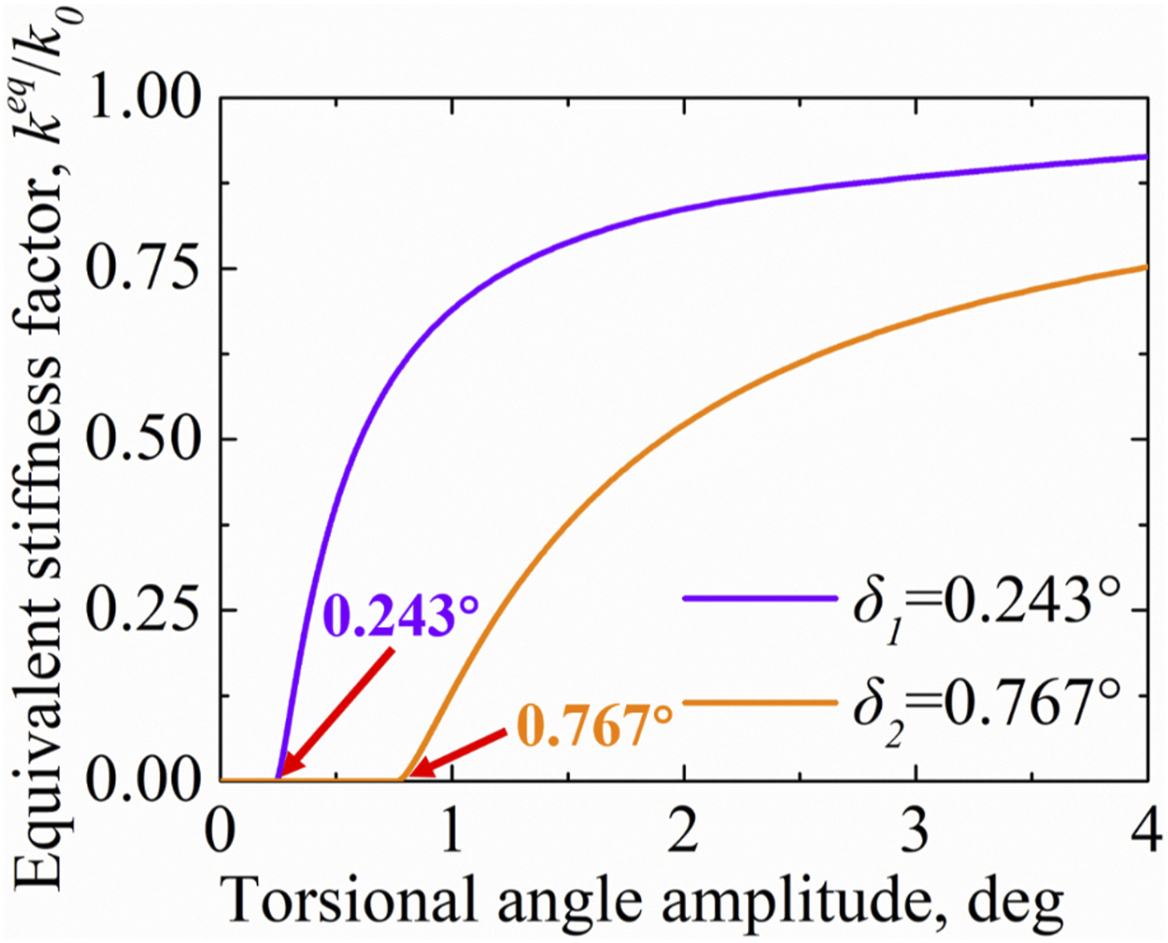
), respectively. According to the geometric relationship of the horizontal tail, the torsional free-play angle δ can be obtained by equation (21) Torsional free-play angle measurements. The equivalent stiffness factor at different torsional angle amplitudes.
Data acquisition in wind tunnel tests
The experimental model arranged in wind tunnel is shown in Figure 12. The torsional angle is measured by a strain gauge which is glued to near the fixed end of the torsional leaf-spring, and the experimental sampling rate of the strain gauge is 128 Hz. In addition, a disturbance device consisting of switch, conduit, and air pump is designed to implement the initial disturbance in the wind tunnel test. When the flow field reaches the arranged flow velocity value and is in a steady state, the switch is operated so that the high-pressure air in the air pump is sprayed to the trailing edge of the model. The time duration of the initial disturbance is 1 s. The experimental data is measured if the collected dynamic response reaches a steady state again after the initial disturbance. Wind tunnel experiment arrangement.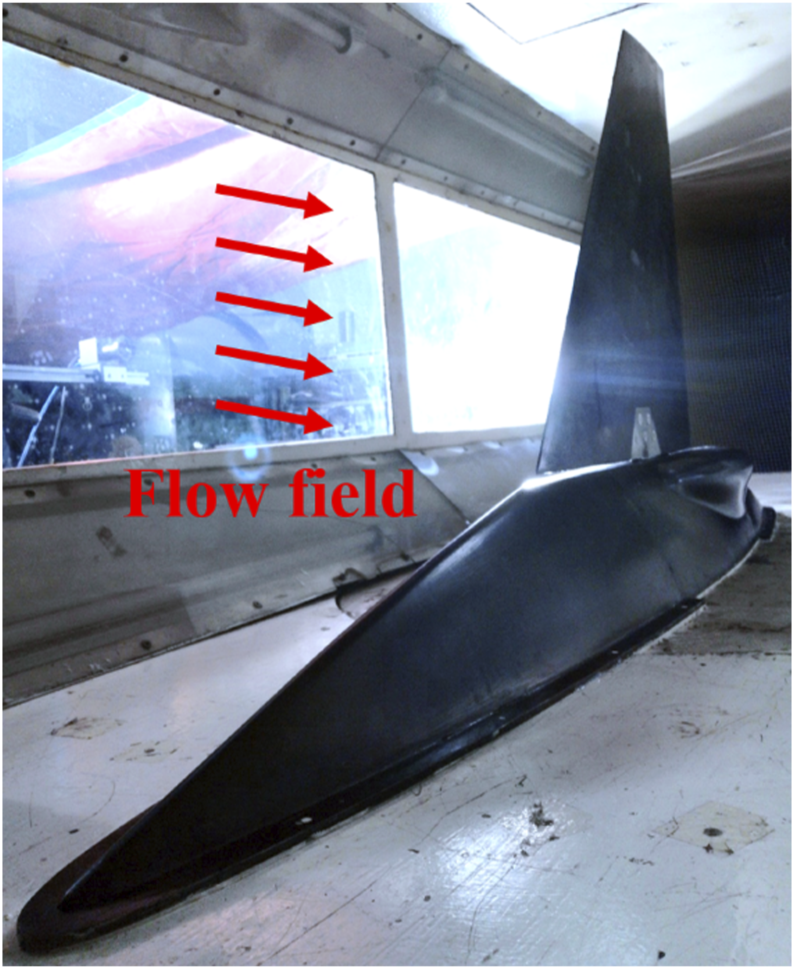
Results and discussion
Limit cycle oscillation amplitude and frequency
Preliminary calculation of LCO behavior for different initial parameters was carried out by the classic DF method, and its results were compared with the experimental ones. The LCO amplitude of torsional angle related to different flow velocity is shown in Figure 13. It includes experimental and numerical results for two torsional free-play angles: δ = ±0.243° and ±0.767°. Both experimental and numerical results show that the value of torsional free-play angle has no significant effect on the critical flow velocity that leads to the occurrence of LCO. The LCO appears at 14 m/s in numerical result, while the experimental LCO is observed at flow velocity is approximately larger than 26 m/s. Previous studies have also shown that the critical velocity of LCO measured in the experiment may be several times higher than the numerical result,
24
such result is recognized as an error caused by the dry friction torque in the actuating system. Without the dry friction torque, the LCO is expected to occur at a lower flow velocity. Besides, the maximum flow velocity of the numerical calculation is 77 m/s, which is also the calculated critical flutter velocity of the linear system without free-play, since an oscillating divergence will occur when the flow velocity is greater than the linear critical flutter velocity. However, in order to avoid the damage of the model, the flow velocity of the experiment is less than 33 m/s. It is also seen that the amplitude of torsional angle increases with the increasing torsional free-play angle and flow velocity. Amplitudes of the torsional angle at different flow velocities.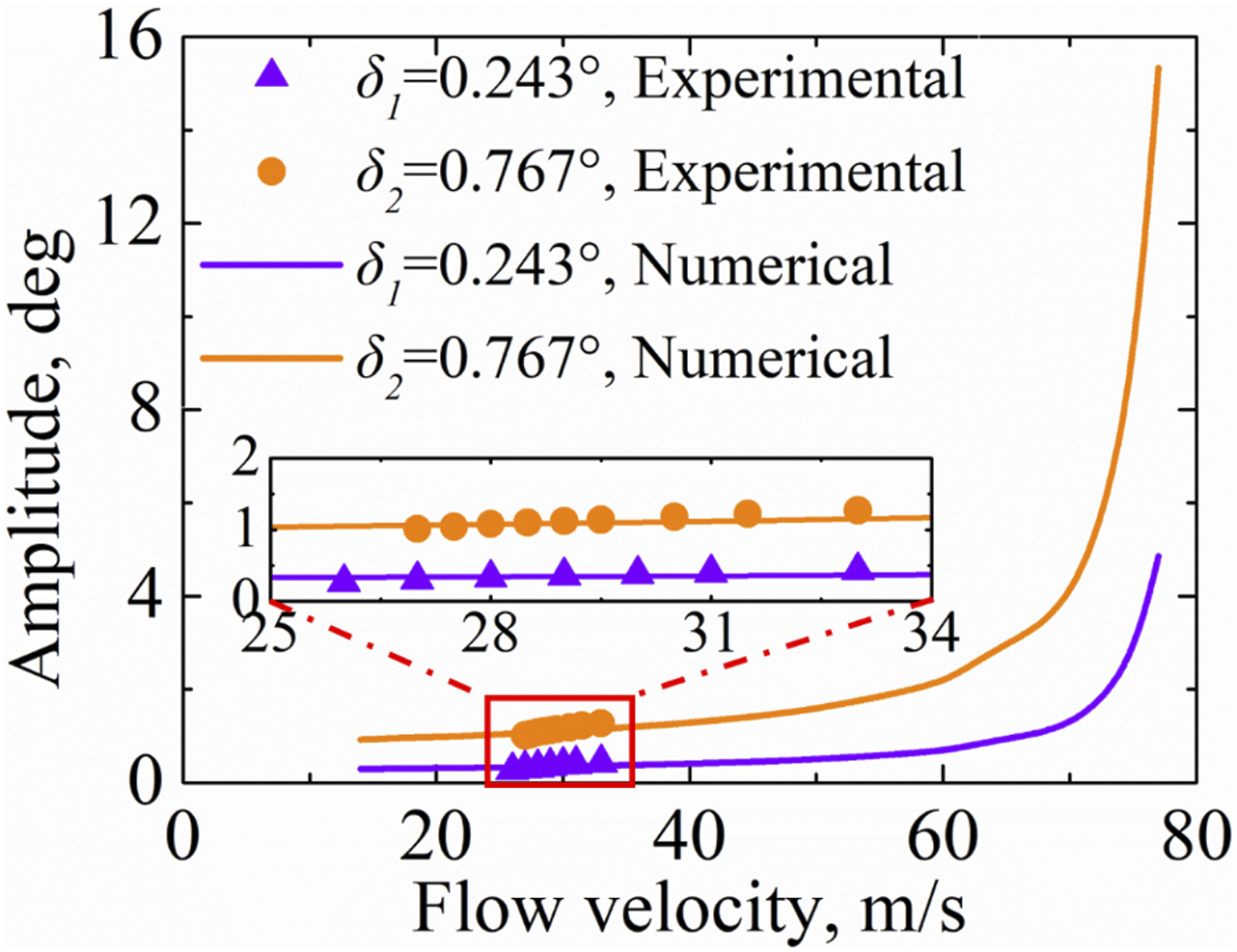
Referring to the method proposed by Tang and Dowell,
24
the amplitude of torsional angle is dimensionless by the torsional free-play angle to quantitatively investigate the effect of torsional free-play angle on LCO amplitude, as shown in Figure 14. Both experimental and numerical results show that the dimensionless amplitude of the torsional angle is the same for different torsional free-play angles. Therefore, the torsional angle amplitude is proportional to the torsional free-play angle. Dimensionless amplitudes of the torsional angle at different flow velocities.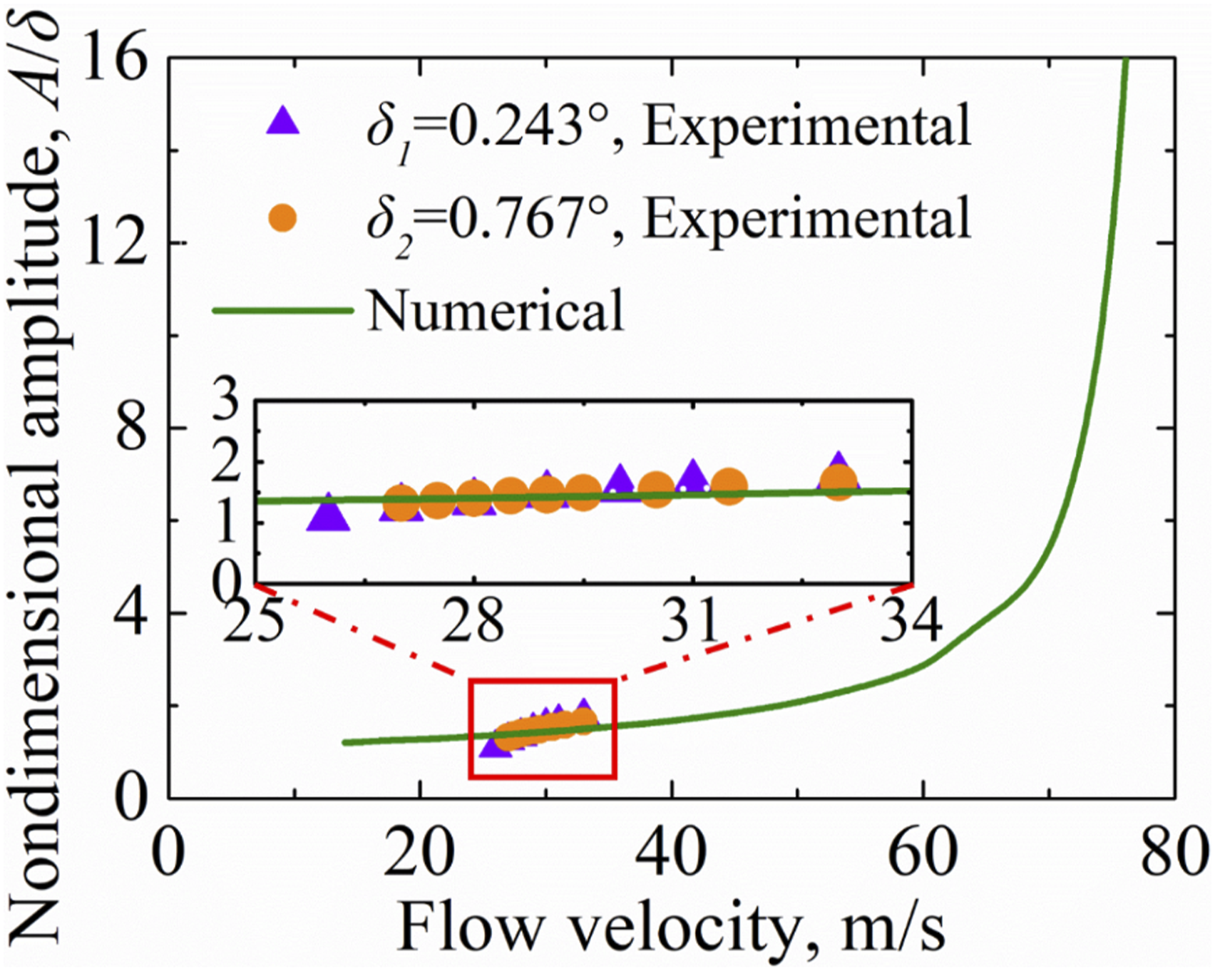
FFT is performed on the measured torsional angle to obtain the main frequency of LCO, and the main frequencies of experimental and numerical results are shown in Figure 15. It can be seen that the main frequency measured in the experiment is slightly less than that from the numerical result. The main frequency increases almost linearly with the flow velocity and it is hardly affected by the torsional free-play angle. Main frequency at different flow velocities.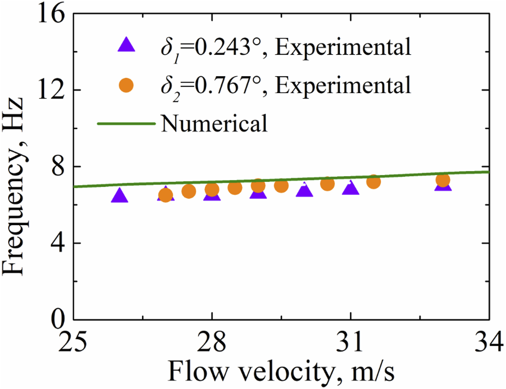
The amplitudes and main frequencies calculated by the classic DF method are consistent with the experimental results within the flow velocity range of experiment (V ≤ 33 m/s), which provides a reliable basis for the subsequent prediction of LCO behavior by the present developed DF method.
Time history and phase portrait
Time history, phase portrait, and frequency spectrum are effective methods for nonlinear aeroelastic analysis.
24
In this section, the time history and phase portrait of LCO are calculated by the developed DF method. Its results are also compared with the experimental results. The time histories of torsional angle for δ = ±0.243° and δ = ±0.767° are shown in Figures 16 and 17, respectively, (i.e., V = 33 m/s is taken as an example). Consistent experimental and numerical results demonstrate the effectiveness of the present developed DF method for calculating the time history of free-play-induced LCO. Time history of the torsional angle for δ = ±0.243° and V = 33 m/s. Time history of the torsional angle for δ = ±0.767° and V = 33 m/s.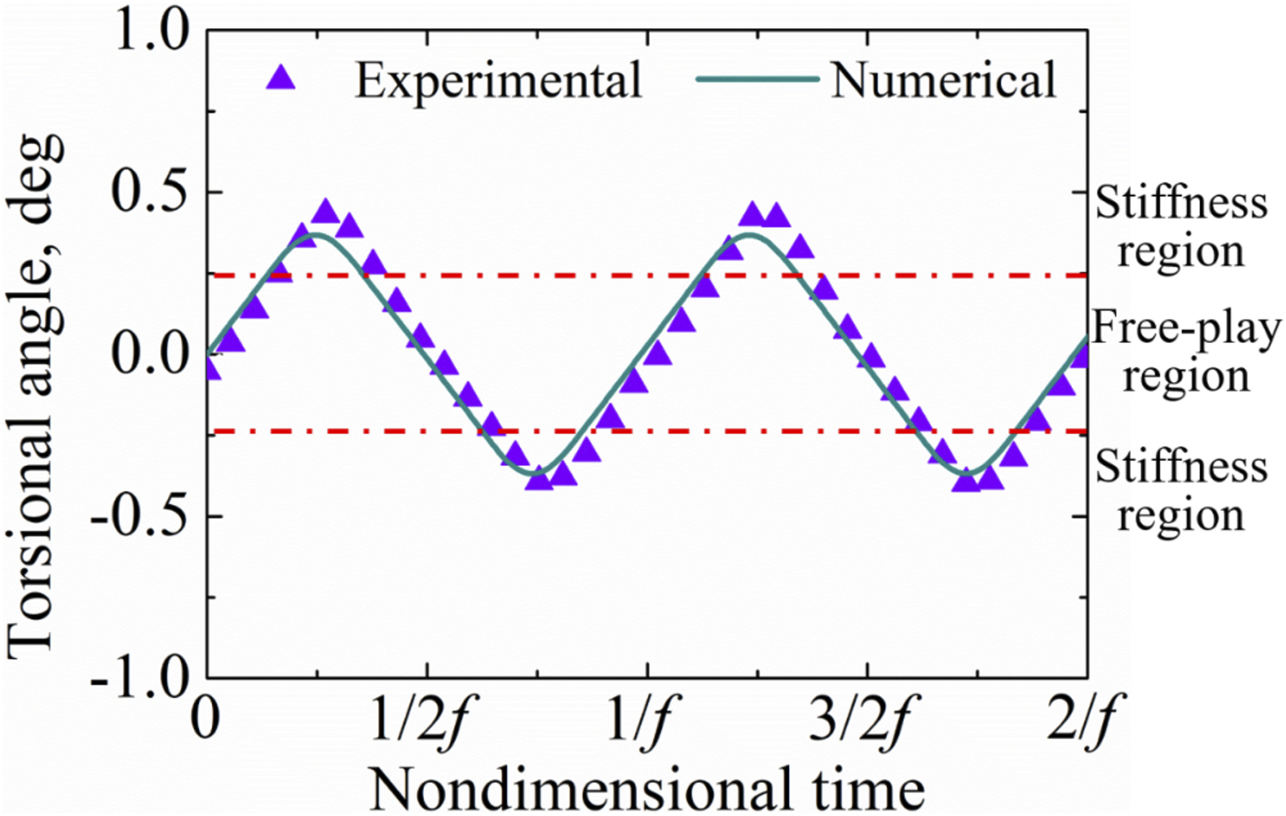

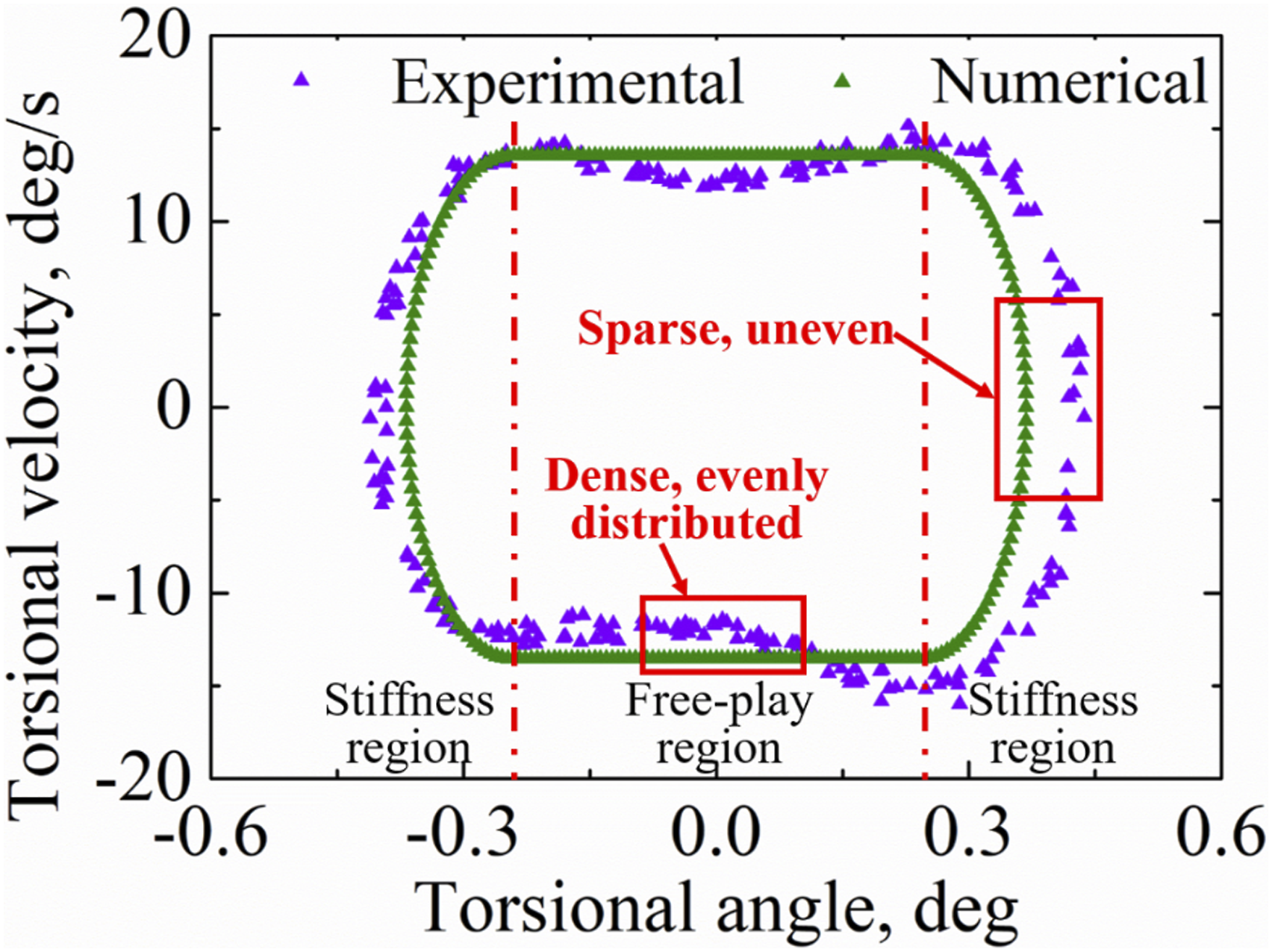
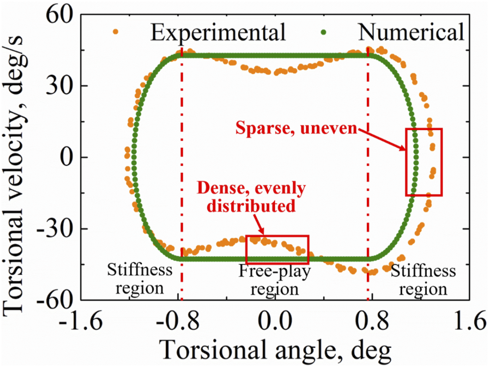
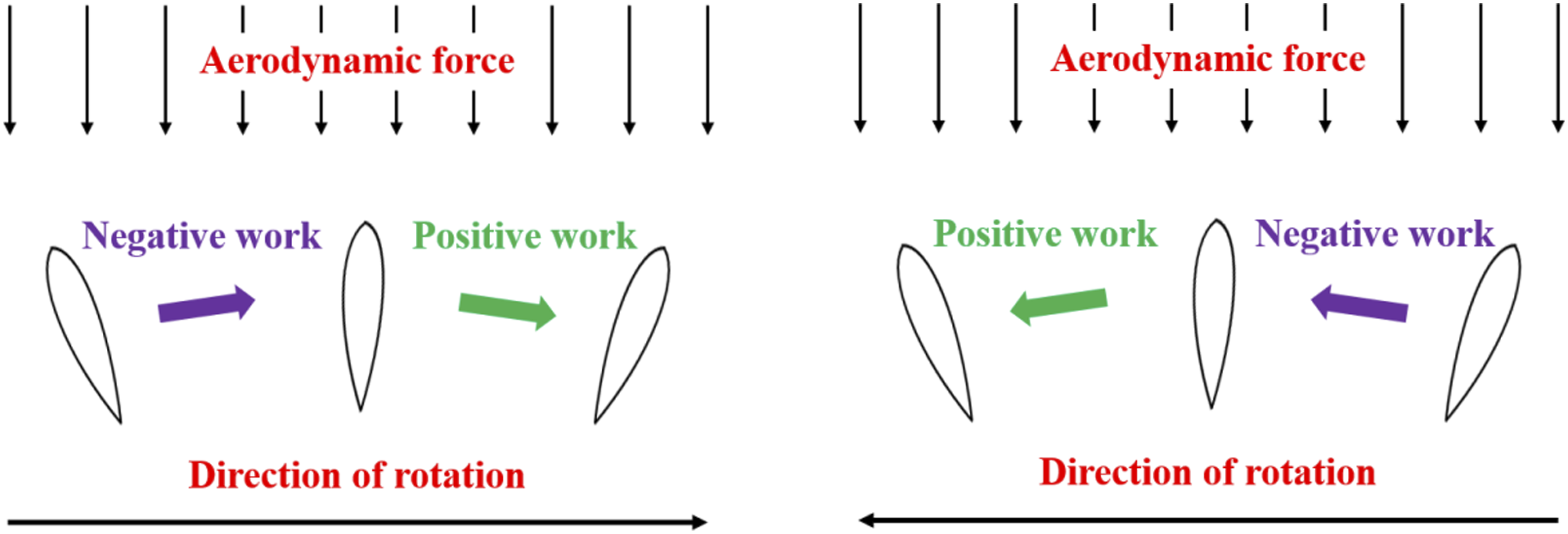
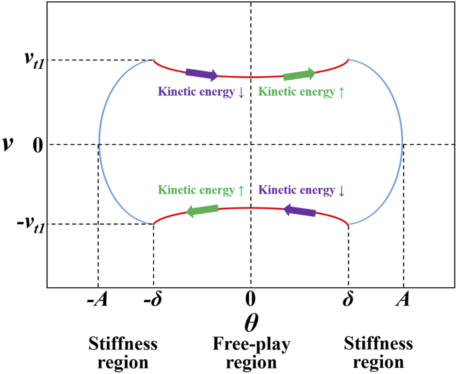
The phase portraits of the torsional angle and torsional velocity are shown in Figures 18 and 19. In which 256 consecutive points measured in the experiment and 256 consecutive points obtained by numerical calculation were included. Consistent experimental and numerical results show that the density of points is approximately constant in the whole free-play region. It indicates that the change of velocity in the free-play region is little. However, the points are sparser where the torsional velocity approaches 0 in the stiffness region. This result indicates that the absolute value of acceleration reaches its maximum at zero torsional velocity. This phenomenon can also be proved numerically by taking the time derivative of equation (14), and can be expressed as The phase portrait of the torsional angle and torsional velocity for δ = ±0.243° and V = 33 m/s. The phase portrait of the torsional angle and torsional velocity for δ = ±0.767° and V = 33 m/s. Effects of aerodynamic work. The modified phase portrait of the torsional angle and torsional velocity.
High-order harmonics
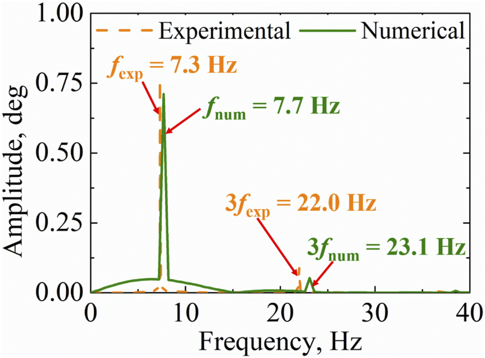
FFT was adopted on the numerical and experimental time histories, respectively, to analyze the high-order harmonics induced by free-play. Figures 22 and 23 show the FFT frequency spectra for δ = ±0.243° and δ = ±0.767°, respectively (i.e., V = 33 m/s is taken as an example). The experimental and numerical results show a reasonably good quantitative agreement for the main frequencies and corresponding peak response values. The 3rd harmonics are observed in both experimental and numerical results. Such nonlinear results can be recognized as a kind of typical characteristic of LCO induced by free-play.42,43 Compared with the classic DF method, the present developed DF method has an advantage of predicting the high-order harmonics accurately. Therefore, it is conducive to propose the mechanism of free-play-induced LCO and demonstrate the aeroelastic behaviors induced by free-play. Frequency spectrum via δ = ±0.243° and V = 33 m/s. Frequency spectrum via δ = ±0.767° and V = 33 m/s.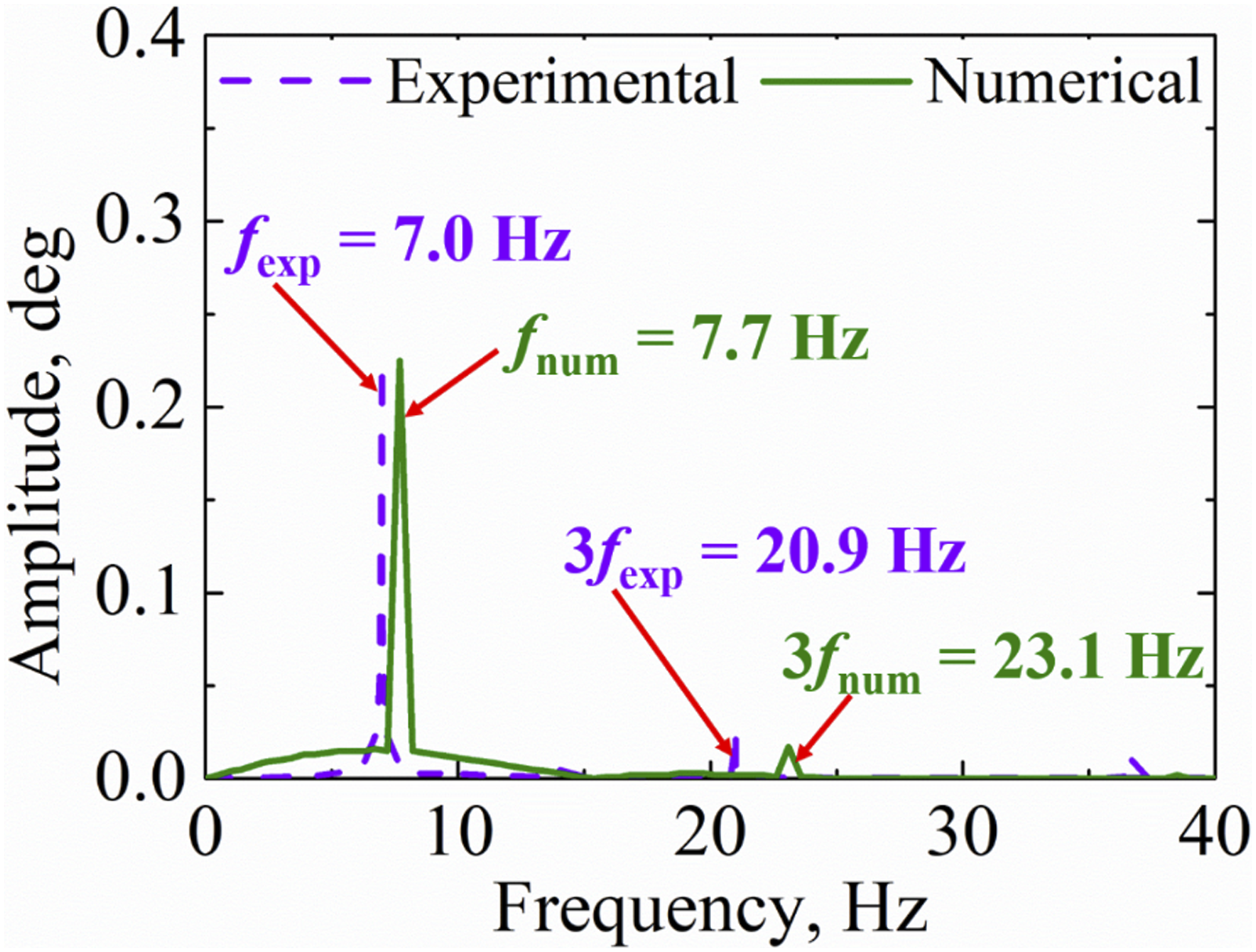
Conclusions
Nonlinear characteristics and physical mechanism of aeroelastic behaviors induced by all-movable horizontal tail free-play were investigated in this work. Structure design, numerical modeling and calculation, and wind tunnel test are presented. The conclusions are summarized as follows: (1) A developed DF method is proposed to predict the complex dynamic response induced by horizontal tail free-play. The developed DF method can be implemented as quickly and easily as the classic DF method, whereas provide a better understanding of the LCO mechanism of a horizontal tail with free-play. The main advantages of the present method over the classic DF method include: the ability to estimate the time history and phase portrait of LCO accurately; and predict high-order harmonics effectively. (2) In order to verify the developed DF method, an experimental all-movable horizontal tail model with adjustable torsional free-play was designed and manufactured to implement wind tunnel tests. The calculated time history and phase portrait are in good agreement with the measured results in wind tunnel tests. The high-order harmonics obtained by the developed DF method are also verified by the experimental results. These comparisons demonstrate that the proposed method is accurate and can be applied to the aeroelastic response analysis of the all-movable horizontal tail with free-play. (3) The influence of the initial parameters of the all-movable horizontal tail on LCO behavior is presented. Consistent experimental and numerical results demonstrate that the amplitude of LCO increases with the increasing free-play angle and flow velocity. Further analysis indicates that the LCO amplitude is proportional to the free-play angle. Meanwhile, the frequency of LCO increases almost linearly with flow velocity and it is independent of the free-play angle.
Footnotes
Declaration of conflicting interests
The author(s) declared no potential conflicts of interest with respect to the research, authorship, and/or publication of this article.
Funding
The author(s) received no financial support for the research, authorship, and/or publication of this article.