
Abstract
The aim of this work was to assess the capability of a hydraulic bottle jack to control vibrations and the effects of earthquakes. The first stage of the present investigation focused on determining the axial stiffness of the apparatus, in order to relate its behavior to that of a linear elastic element. To do this, uniaxial compression tests were carried out using a manually controlled servo system. In the second stage, a conceptual application based on the field of mechanical vibrations was considered. The experimental results confirmed the hypothesis of linear behavior and showed that the stiffness coefficient had distinct values of magnitude that depended on the cylinder height. Simulations were conducted in which the frequencies and the peak displacements of an idealized SDOF system subjected to earthquake excitation were adjusted based on the experimental stiffness. It was possible to conclude that the equipment analyzed here is an effective tool for controlling vibration and reducing displacement during a seismic event, and can be calibrated according to the specific conditions of operation. This is an important aspect of safety and functionality for mechanical and structural systems.
Keywords
Introduction
A hydraulic jack is a system designed for the application of mechanical forces, and is typically used for lifting loads. It is often found in the automotive and industrial sectors, in a wide range of areas. Bottle models are used in various applications, and have different lifting capacities ranging from 18 to 445 kN 1 (∼2 to 50 tons, where the acceleration of gravity g is assumed to be equal to 9.807 m/s2). This is one of the simplest and basic forms of hydraulic equipment; it is also very versatile and has no load limitations in its current uses. Furthermore, the hydraulic jack is one of the most efficient types of equipment for improving traditional construction processes and structural projects. 2 The use of these jacks to lift heavy civilian structures has become relatively common, especially in the field of repair and recovery, 3 specific techniques have been developed for using them with bridges 4 and buildings, 5 including in historic and heritage projects, 6 and even as support tools in constructive/excavation processes,7,8 rock breaking, 9 and as movement stabilizers. 10 Bottle-type jacks became popular in 1990 following developments in the automobile industry, but are also used in the medical area as components of hydraulic stretchers and inpatient elevators, in the repair of agricultural machinery, and for testing and construction operations. 11 These applications illustrate the flexibility of the use of hydraulic jacks and their contribution to various sectors of industry and construction.
During the application and removal of a force in the operation of a hydraulic jack, it is possible to observe its capacity to recover from the deformation imposed on it, and when used in applications of a dynamic nature, to restore the oscillatory movement induced in a system. Based on this observation, a hypothesis that a hydraulic jack can be represented mathematically as a spring has been assumed. It would then be possible to directly associate the properties of a spring with the behavior shown by a hydraulic jack when compressed. Even with oil inside, a hydraulic jack has been shown to undergo elastic behavior similar to that of a spring, whose stiffness can be obtained experimentally.
If it can be represented as a spring, a hydraulic jack could be used to carry out tasks related to vibration control, including the mitigation of harmful earthquake effects, as springs are widely used in the modeling and control of several kinds of mechanisms.12,13 They are especially used for vehicular suspension,14,15 including devices based on the concept of air springs, where the mechanical properties and the spring coefficient are determined experimentally. 16 Air is a fluid, in the same way as oil, but with much lower density and viscosity. Based on the concepts described above, a hydraulic device has been used to change the structural stiffness of a thrust mechanism for geotechnical applications. 17 To do this, its cylinders were simulated as springs, based on Hooke’s law. 18
Springs are essential elements in the field of vibration. They are used in the operation of several machines, especially when it is necessary to restore a system to its equilibrium position. 19 The stiffness of a spring (also known as the spring index or elastic constant) is its main characterizing parameter or attribute. 20 A spring is capable of converting the accumulated strain energy 21 into work when the force is removed. This concept has found a wide range of applications in engineering problems, where a typically elastic behavior is an intrinsic part of the process.22–27 In view of their properties, springs have been used as energy absorbers, to command and revert mechanical systems, interceptors of static and dynamic forces, to strengthen joints, as dampers in anti-vibration protection systems, and as devices for controlling and measuring force. 28 In mathematical terms, a system consisting of springs can be solved by numerical methods 29 or through the use of advanced analytical techniques. 30
Based on the concepts outlined above, a control system formed of springs and an inertial mechanism, whose principle of operation was based on the proportionality of applied forces, has been studied for suppressing the vibration of beams under moving loads. 31 Control systems based on applied forces have also been assessed by simulating a pulse-type ground motion, 32 they have been treated numerically by considering a hydraulic system with variable inertia (e.g., a valve-controlled power hydraulic system as a vibration isolator) 33 and experimentally by employing a jack as a control device. 34 In addition, hydraulic jacks with variable stiffness have been computationally assessed for use as control devices to attenuate the displacement of a building under seismic action. 35
In this work, a device called a hydraulic bottle jack (model CJ8-8700, manufactured by Bovenau1) with a capacity of 71 kN (∼8 tons) has been investigated. It had a maximal hydraulic lift stroke of 147 mm and a cylindrical, bulky design, and was versatile, practical, and simple to use. Laboratory tests were carried out to obtain the axial stiffness (or spring coefficient) of this apparatus, taking into consideration the real complexity of a mechanical system of this nature and its internal interactions. The study consisted of a uniaxial compression test of a manually controlled system, adopting seven levels of elevation for the cylinder height, to explore its behavior under quasi-static loading conditions. Following this, a conceptual simulation based on mechanical vibrations was carried out to assess the capability of the device to mitigate the harmful effects of an earthquake event.
Operational principles and main characteristics of the apparatus
The operation of a hydraulic jack is based on the movement of a piston located inside a hollow cylindrical body, which acts as a hydraulic press according to Pascal’s principle. 36 The first hydraulic press was developed by the mechanic Joseph Bramah, who received recognition for his invention from the British Patent Office in 1795. 37 The machine invented by Bramah used water as a fluid to move the pistons; nowadays, however, mineral oil is used to fulfill the same function, as it is an almost incompressible fluid, which enables the transmission of force almost instantly and contributes to a reduction in friction due to the high lubrication it provides, consequently reducing the wear of moving parts in hydraulic components.
Following the invention presented by Joseph Bramah in 1795, Armstrong developed the first hydraulic crane in 1850, together with the first hydraulic accumulator. 38 Almost 50 years later, in the United States, Cooper and Hampton 39 registered the first patent for an axial piston pump in 1893. The origin of the hydraulic jack can be traced to Richard Dudgeon, a machinist, owner and inventor, who invented the so-called “portable hydraulic press” 40 in 1851, receiving a patent for this creation. 41
The operation of a hydraulic jack occurs through the repeated application of a force via a lever, which results in the oil flowing from the reservoir into the cylinder, 42 thus raising the required load. 43 The main advantages of a hydraulic system are its easy handling, flexibility, and the possibility of fine adjustments when compared to mechanical and electrical ones. Hydraulics also have a small weight: size: power consumption ratio compared to other systems, and provide security to the user, since when they are overloaded, their operation is interrupted. 44 Their principal elements include a pumping mechanism, oil, and valves: the pumping mechanism supplies energy to the system, while the valves control the oil flow and pressure,45,46 and the oil lubricates the internal parts and transmits the pressure imposed by the pump to the lifting chamber. 47 The pressure created in this way represents the reaction of the system to the applied (or sustained) force. However, precise control over the pressure level has been a recurring challenge for manufacturers 48 aiming to establish reliability and good operating conditions.49–51
A hydraulic system provides constant power, works well in hot environments, and uses a high-density incompressible fluid that reduces the possibility of leaks, thereby reducing maintenance costs. However, the selection of the hydraulic fluid is an important aspect that should be considered because it may corrode parts that are essential for the functioning of the system, such as the cylinder elevation. In addition, small impurities present in the fluid can result in permanent damage to the device, 52 which makes it necessary to install suitable filters. After use, fluids must be disposed of properly, as they are harmful to the environment. 53 Hydraulic machines use fluid energy to carry out work by transmitting a high-pressure liquid, also known as hydraulic fluid, through hydraulic cylinders. 54 Accurate determination of the hydraulic stiffness is critical in the design and control of hydraulic mechanisms. 55
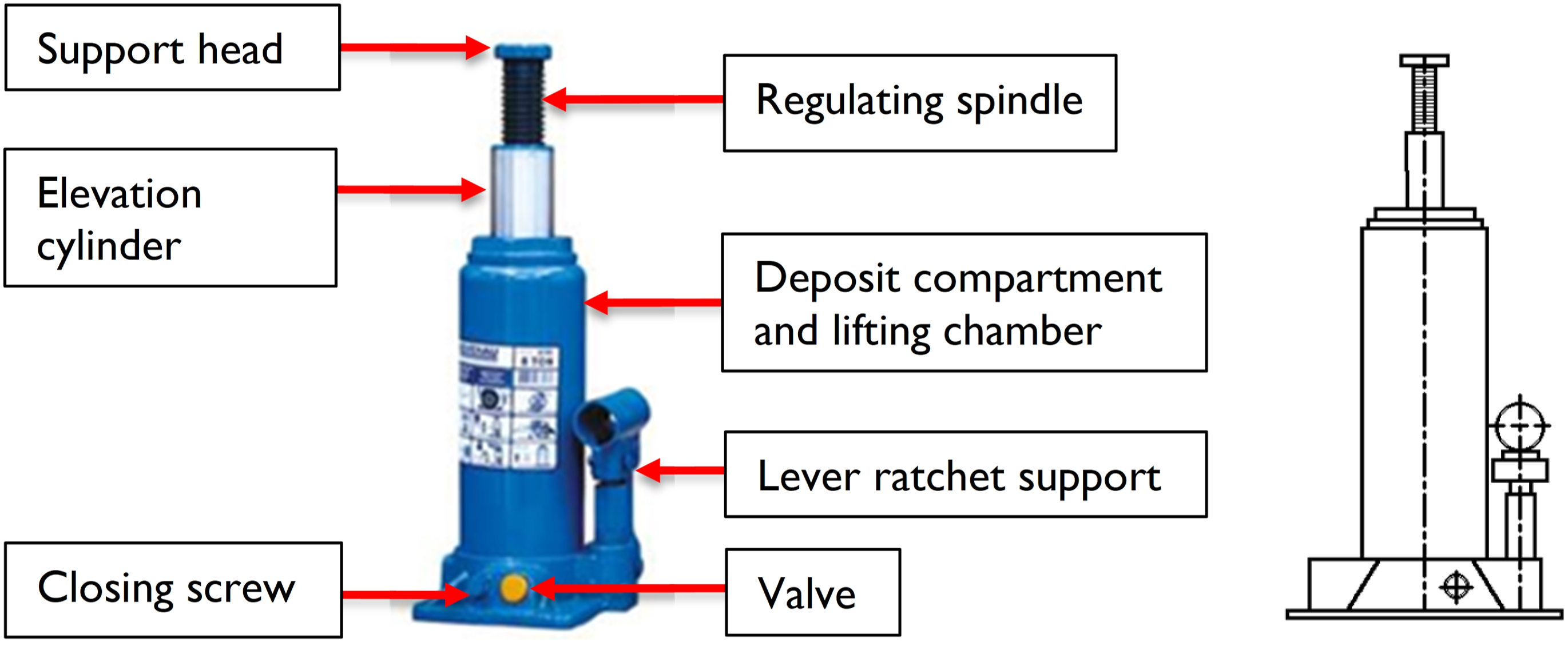
Hydraulic bottle jacks have a shape that resembles a bottle, with a cylindrical body and a neck, hence their name. This type of device features two concentric chambers, one of which is internal and the other external. The former is responsible for actuating the piston, while the latter is used as a reservoir for oil. In the process of operation, the plunger is pushed forward, the oil moves through an external discharge check valve to the chamber cylinder, and the suction valve closes, resulting in increased pressure inside the cylinder. In this type of jack, the piston is vertical, and supports an extension screw that is in direct contact with the object to be lifted. 56
The hydraulic jack tested in this work (CJ-8700 model) was supplied by Bovenau Technical Metal Ltd
1
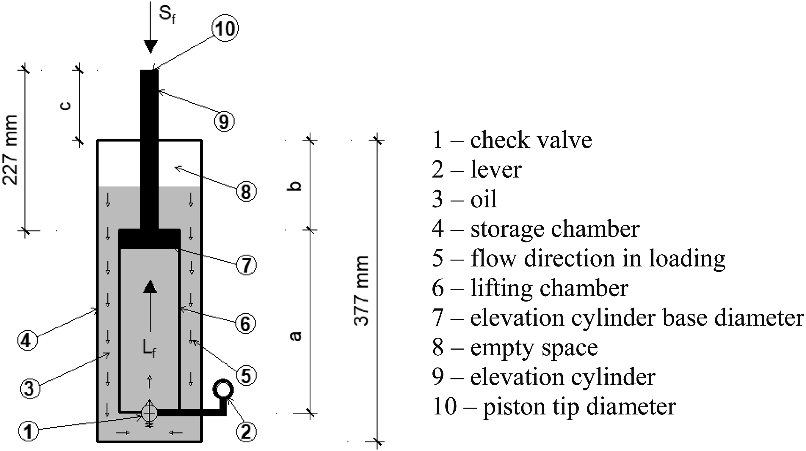
It had a nominal load capacity of 71.17 kN (8 tons of force), a construction height of 230 mm, base dimensions of (119 x 122) mm, a hydraulic lift stroke of 147 mm, a spindle stroke of 80 mm, a total height of 457 mm, a support head diameter of 34 mm, a lever length of 290 mm, and a weight (with lever) of 5.3 kg. The basic operating principles of a hydraulic bottle jack are the same as those of the general hydraulic systems described above. The main components are shown in Figure 1. Hydraulic bottle jack (source: Bovenau).
1
Compression test and axial stiffness
Tests were carried out in a physical laboratory to obtain the axial stiffness of the hydraulic bottle jack described above. The machine used to perform the test consisted of a manually controlled servosystem, and a press equipped with a hydraulic actuator, which was fixed to a metal gantry, with a compression capacity of 142 kN (∼15 tons). This press is illustrated in Figure 2, and was specifically designed to perform compression tests on hydraulic jacks in order to check their specifications and load capacity. It was therefore appropriate for these experiments. Details of the press: (a) frontal, (b) lateral, (c) superior views (dimensions in m).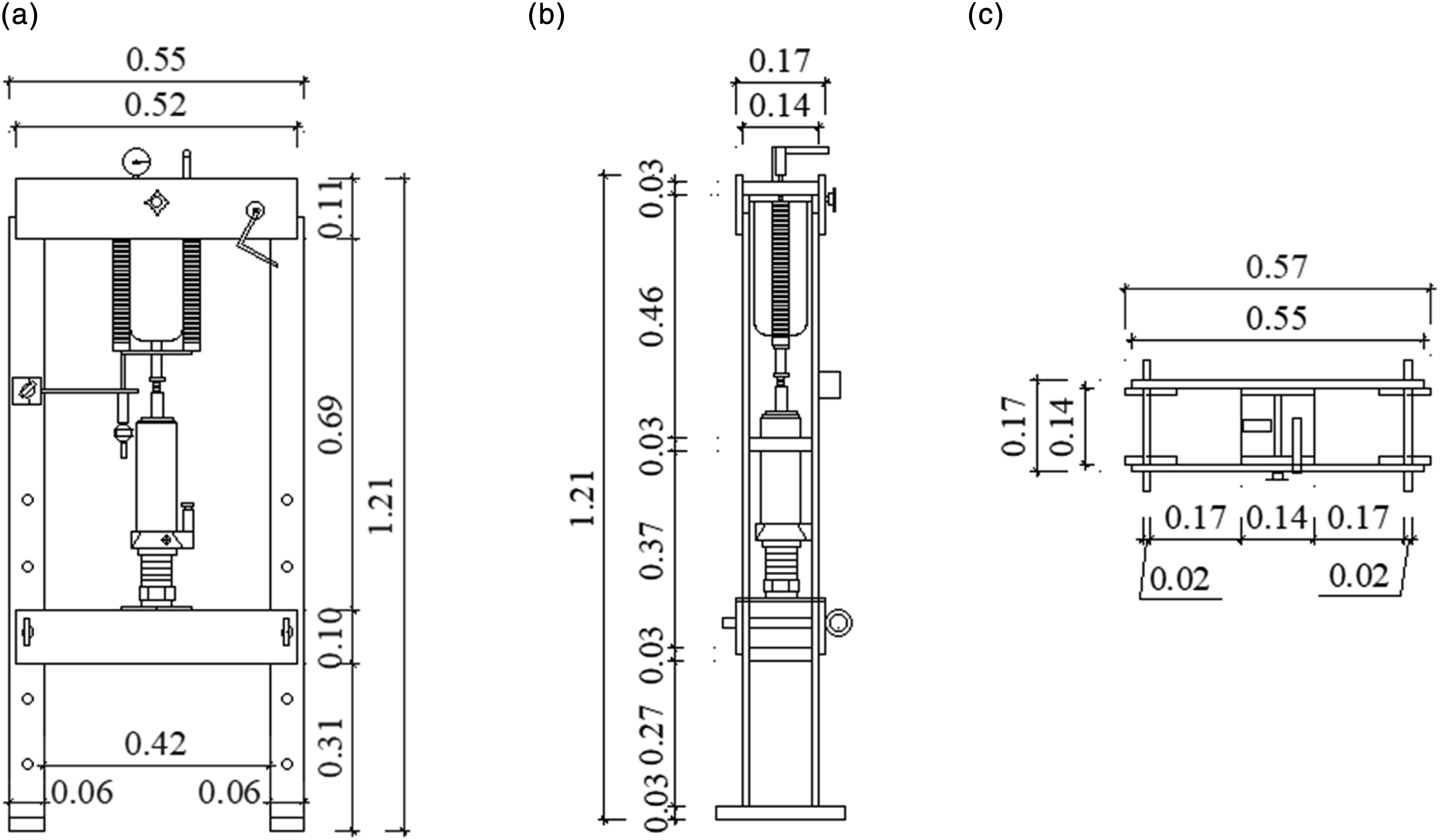
During the test, the hydraulic jack was aligned with the central vertical line of the servosystem, with some shims where necessary. This allowed for the positioning of the jack with the specified cylinder height for the test, and allowed the press to compress it ideally, meaning with the force acting directly on the jack through the centroid of the upper plate of the press, thus reducing any eccentricity effect. The imposed load and the test speed were manually controlled, and the desired force level was established by directly observing the machine indicator dial. A loading plan was applied in which the compression force started at 8.9 kN (∼1 ton) and was increased in intervals of 4.45 kN (∼0.5 ton) until the hydraulic jack’s loading capacity was reached. This force was 3% below Euler’s critical load, 57 which is an important checking parameter for the structural stability of cylinders of hydraulic systems. 58
Results for cylinder displacement from compression test (values in mm).
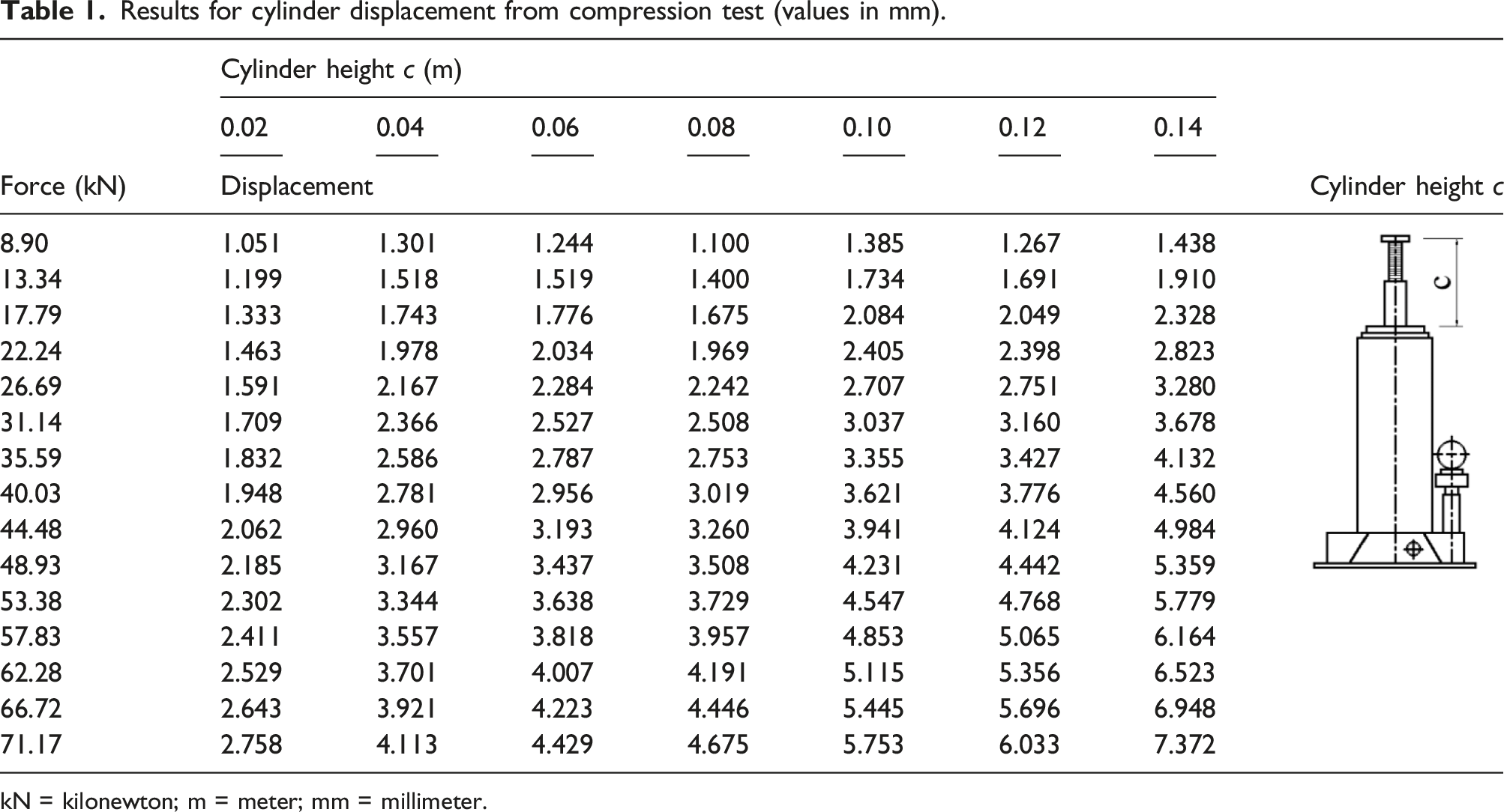
kN = kilonewton; m = meter; mm = millimeter.
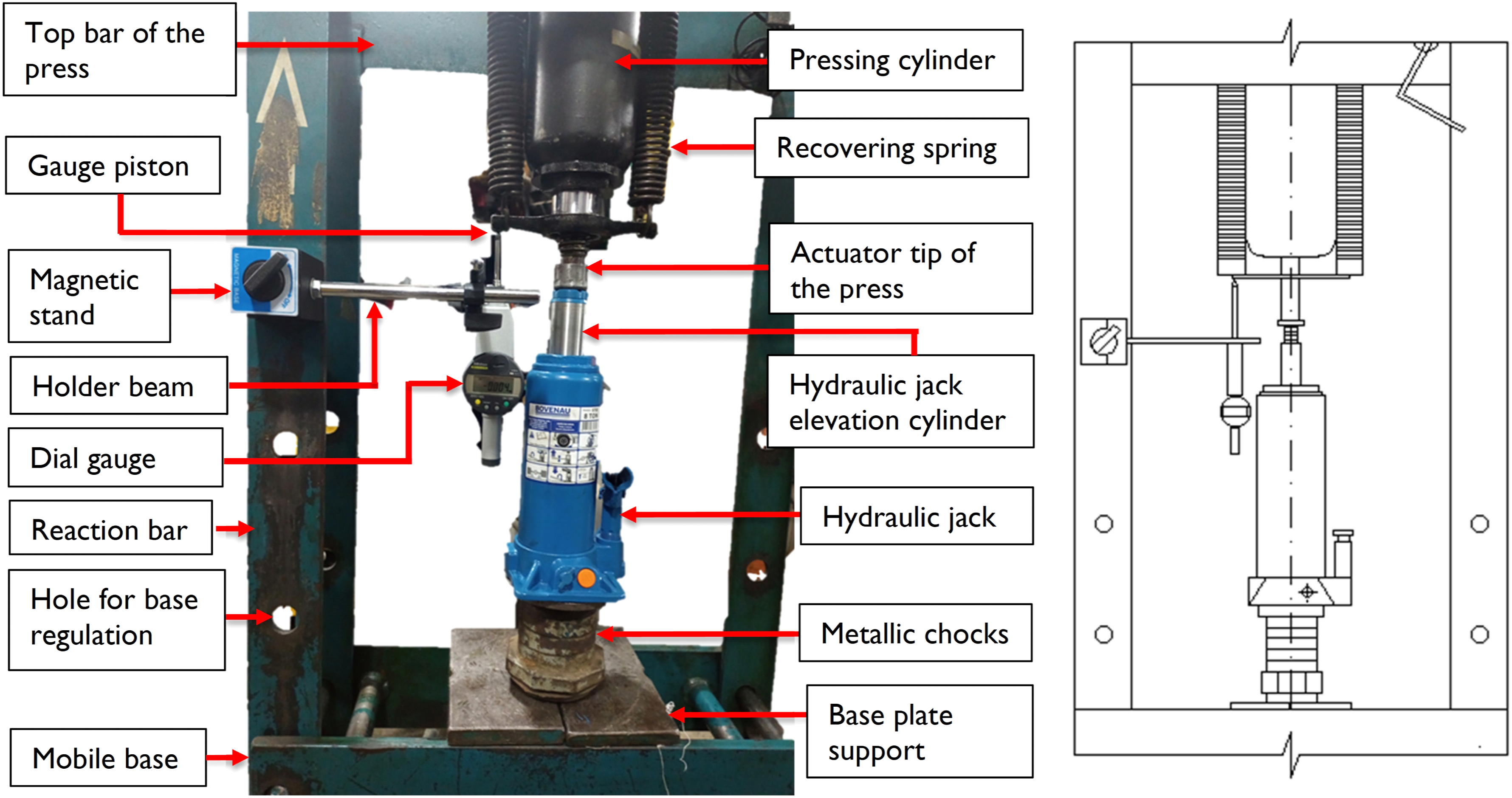
Test setup.
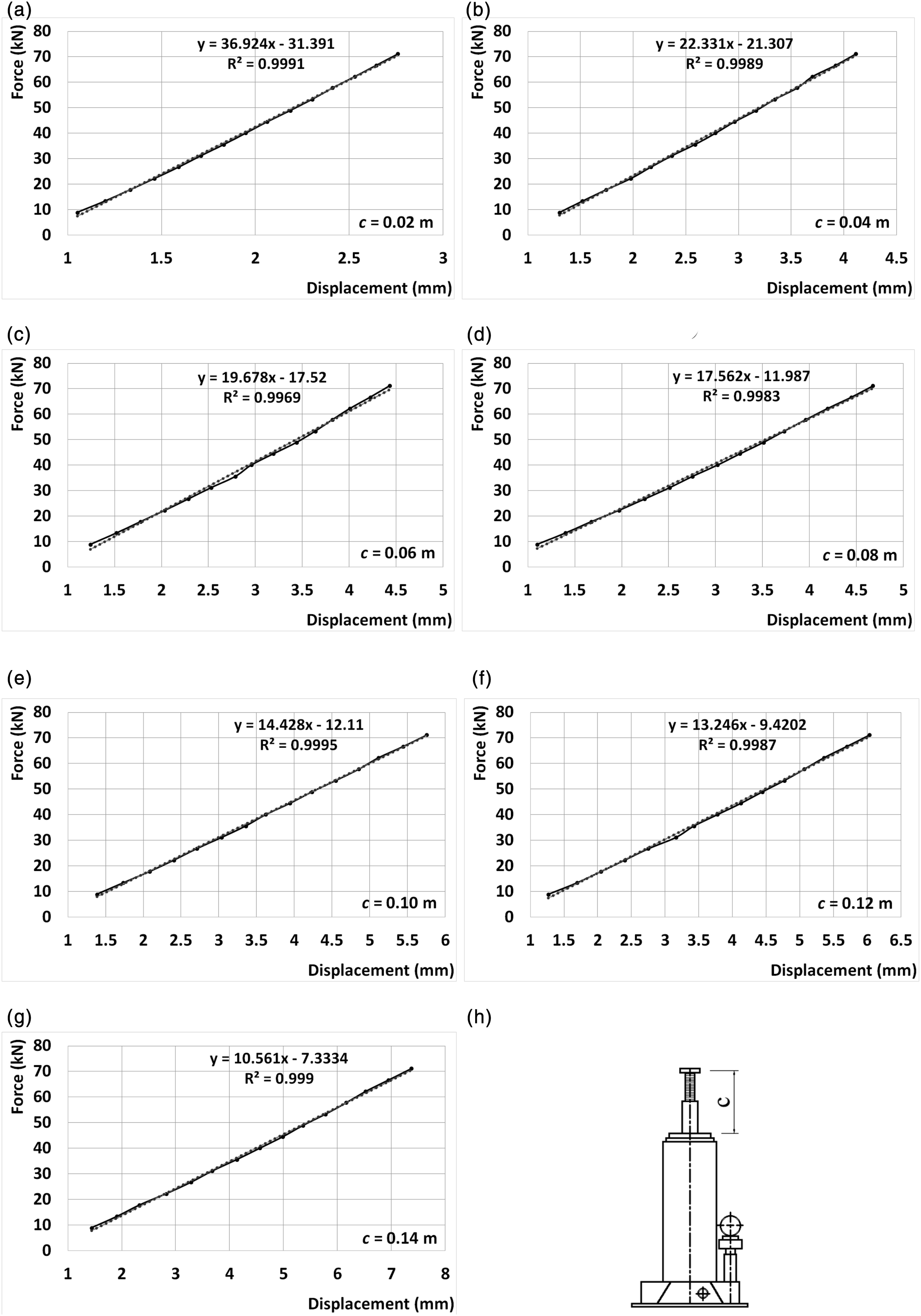
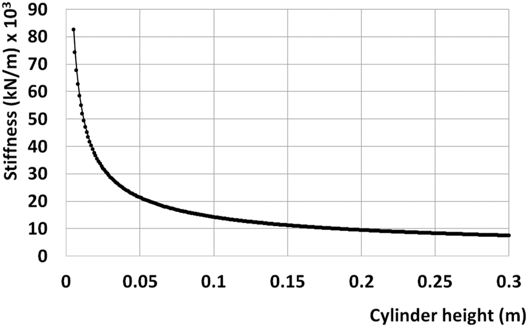
Force versus displacement for different cylinder heights c (in m): (a) 0.02; (b) 0.04; (c) 0.06; (d) 0.08; (e) 0.10; (f) 0.12; (g) 0.14; (h) diagram showing cylinder height.
Assessment of vibration control and mitigation of seismic effects
One possible application that opens up is the use of hydraulic devices for vibration control and the mitigation of undesirable earthquake effects.59,60 To assess this approach, a mass-spring-damper system with a single degree of freedom (SDOF), as shown in Figure 5, was considered. Many practical engineering problems are associated with SDOFs, such as those involving columns,
61
control systems
62
and absorbers,
63
beams,64,65 buildings,
66
bridges,
67
and machine foundations.
68
SDOF mass-spring-damper system.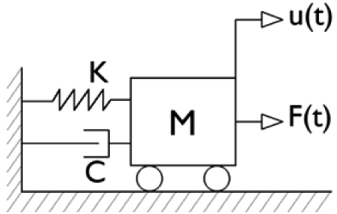
In the representative model, K is the spring stiffness associated with the hydraulic jack, C is the structural damping, and M is the generalized mass of the system. Mathematically, C can be set proportional to M and K when necessary. 69 The oscillatory motion is defined by u(t), and u0 is the initial displacement. A force F(t) characterizes an excitation that makes the system vibrate under damped conditions during and after its application. This force may be of any type, including impulsive, periodic, and seismic. Friction is not considered in that model.
With the appropriate transformations,
70
the horizontal displacement can be obtained as

An important consideration related to the mitigation of earthquake effects is the use of hydraulic jacks to control the undesirable vibration effects that arise from this kind of excitation. For instance, consider the seismic event known as the “El Centro Earthquake,” which occurred in North America in 1940. Its seismographic signal was recorded, and has been used to simulate the effect of seismic waves in applied sciences72–75 since then.
The time series acceleration data for the north-south component
76
and the spectrum of frequencies obtained by using the fast Fourier transform (FFT)
77
of this component are represented in Figures 6(a) and (b), respectively. The peak acceleration a
pk
, with a value of 3.13 m/s2, occurs 2.02 s after the event starts. The largest normalized amplitude n corresponds to 1.17 Hz, over a spectrum from 0 to 25 Hz. “El Centro Earthquake”: (a) time series data; (b) spectrum of frequencies.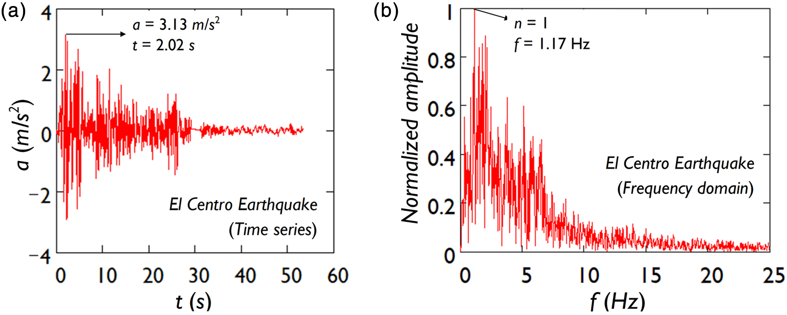
Results and discussion
The results obtained in this study are summarized and discussed in this section.
Compression test and axial stiffness
Results for equivalent experimental stiffness.
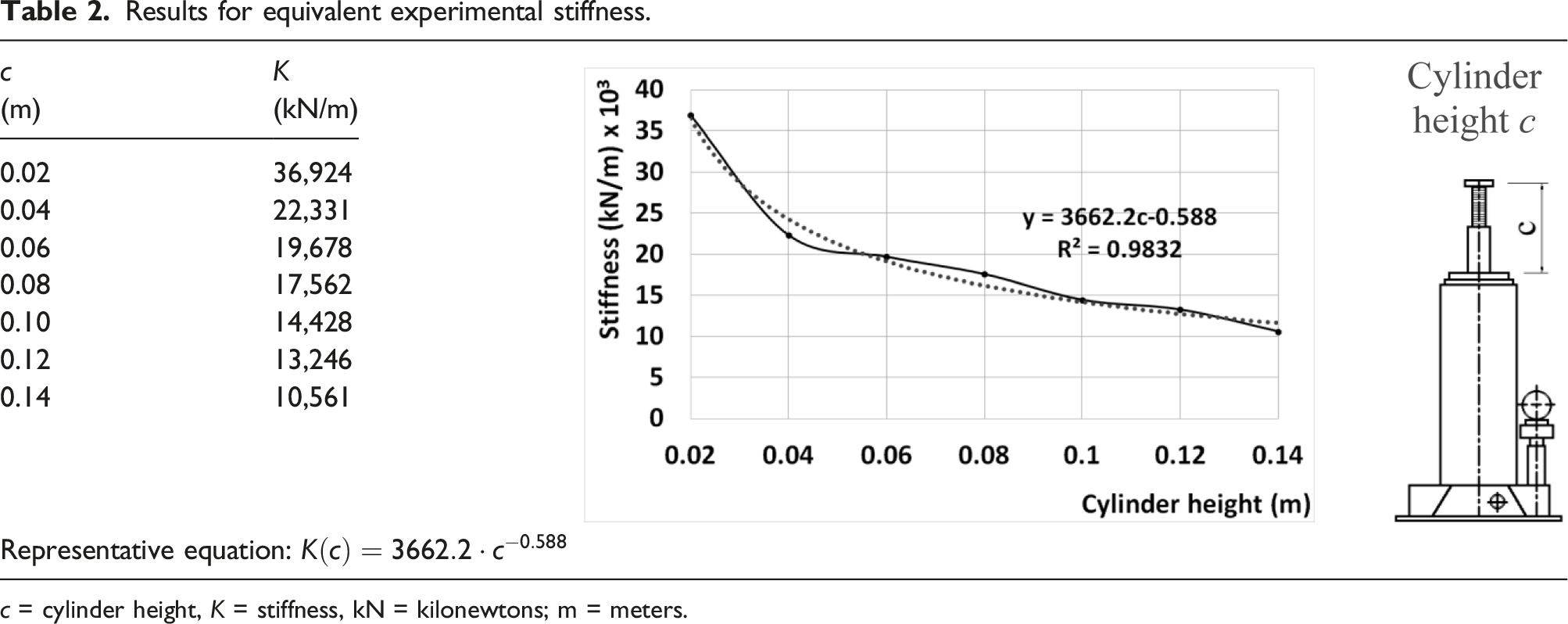
c = cylinder height, K = stiffness, kN = kilonewtons; m = meters.
Plot of the representative equation.
By applying Pascal’s law to the system in Figure 8, it is known that for equilibrium, it is necessary that the force acting at the base of the piston L
f
is equal to the raising force S
f
, which is normally gravitational. L
f
depends on the fluid under pressure acting on an area larger than that of the opposite end of the cylinder, thus producing a force of the same intensity but using much less pressure. Hence, the pressures at both extremities are different. Using equation (3), the force and pressure at the base of the piston p
b
can be found when the force at the top of the cylinder is known, as in the corresponding tests (i) The flow control valve (1), which is initially in the pressure relief position, is placed in the suction-hold condition. (ii) The check valve control lever (2) is manually operated. (iii) The flow of oil (3) in the storage chamber (4) is directed (5) into the elevation chamber (6), which increases the pressure inside it. (iv) The pressure generated by the oil acts on the base of the elevation cylinder (7). (v) The movement of the oil leaves an empty space (8). (vi) The piston (9) is raised due to the internal force L
f
created by the pressure inside the elevation chamber, which modifies the relationship between the dimensions a, b and c. (vii) The external load S
f
in contact with the upper end of the elevation cylinder (10) is lifted and sustained while the valve is kept in the hold condition. Simplified scheme for a bottle hydraulic jack.

During the movement of the lever, the oil leaves the reservoir and is directed to the lift cylinder through the suction-hold valve. The movement of the lever triggers the opening of the valve directing the flow of oil into the lift chamber, which provides sufficient pressure to lift the piston to the desired height. To empty the chamber and allow the oil to return to the reservoir, it is necessary to turn the valve counterclockwise, which permits the oil to flow into the reservoir, thus relieving the pressure inside the elevation chamber and causing the piston to be retracted.
It is important to highlight that along the path taken by the oil, it leaves the reservoir, where it behaves as an incompressible fluid, and enters the elevation chamber, a region that gives the fluid a certain compressibility. At the same time, there is an adjustment of parts during loading. The stiffness of the jack is therefore a result of the interaction between the components and the fluid, readjusting and repositioning of moving parts under charge, and the deformation of the piston and chambers when the system is compressed.
Researchers have sought to establish estimates of the compressibility of hydraulic systems with cylinders of different diameters. The studies have associated this aspect with the small movements of moving parts in existing clearances and the deformation of components, which influences the hydraulic fluid flow rate between chambers, altering, for that reason, the response of the system (i.e., the displacement of the piston). The stiffness coefficient of a hydraulic jack therefore tends to be variable, due to the influence of these factors.78,79
Figure 8 shows the dependence of the dimension of the lifting chamber a on the height of the cylinder c, which can be expressed as in equation (5)
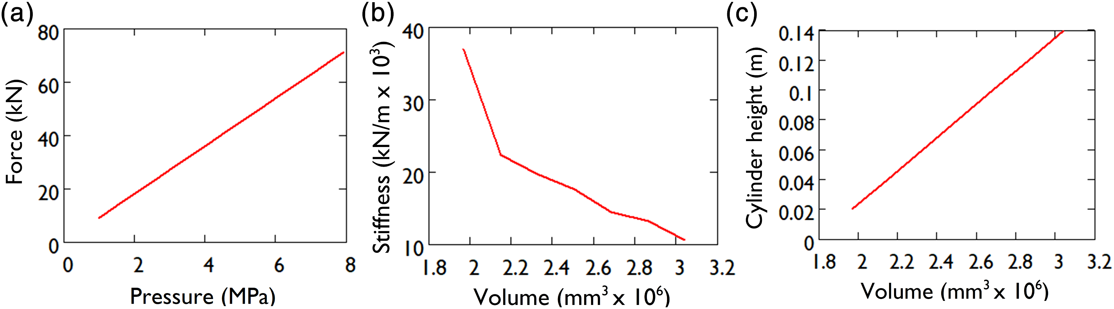
The volume of the elevation chamber therefore becomes a function of the dimension c Relationships between: (a) force and pressure on the base of the elevation cylinder; (b) stiffness and the volume of the elevation chamber; and (c) cylinder height and the volume of the elevation chamber.
Vibration control assessment and seismic effects mitigation
By adopting the values for K from Table 2, with a damping ratio of ξ = 1% (a conservative value found for weakly damped systems,
80
as for buildings it is typically 2% for concrete constructions and less than 5% for steel)
81
and a mass M = 1000 kg, and varying the time from zero to a convenient final instant, it is possible to obtain the frequencies and displacements of the system. The frequencies are given in Figure 10, and displacements in Figure 11. Results for (a) damped natural frequency in rad/s, and (b) frequency spectrum in Hz. Damped response for varying values of Κ (in kN/m): (a) 36924, (b) 22,331, (c) 19678, (d) 17562, (e) 14428, (f) 13246, (g) 10561, (h) diagrams showing the spring model of the hydraulic jack.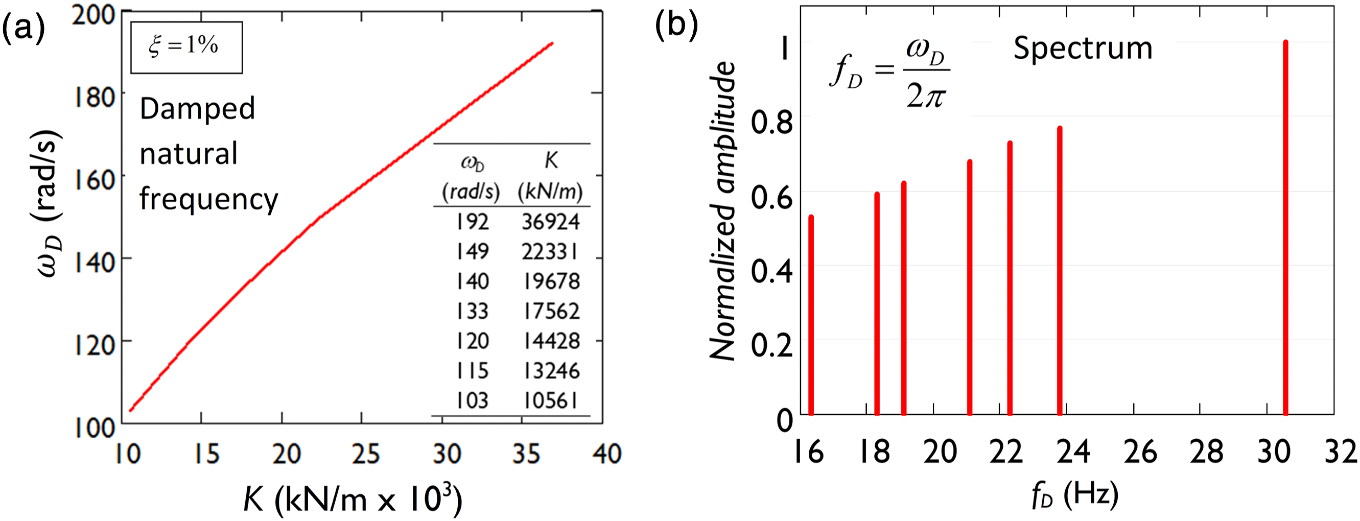
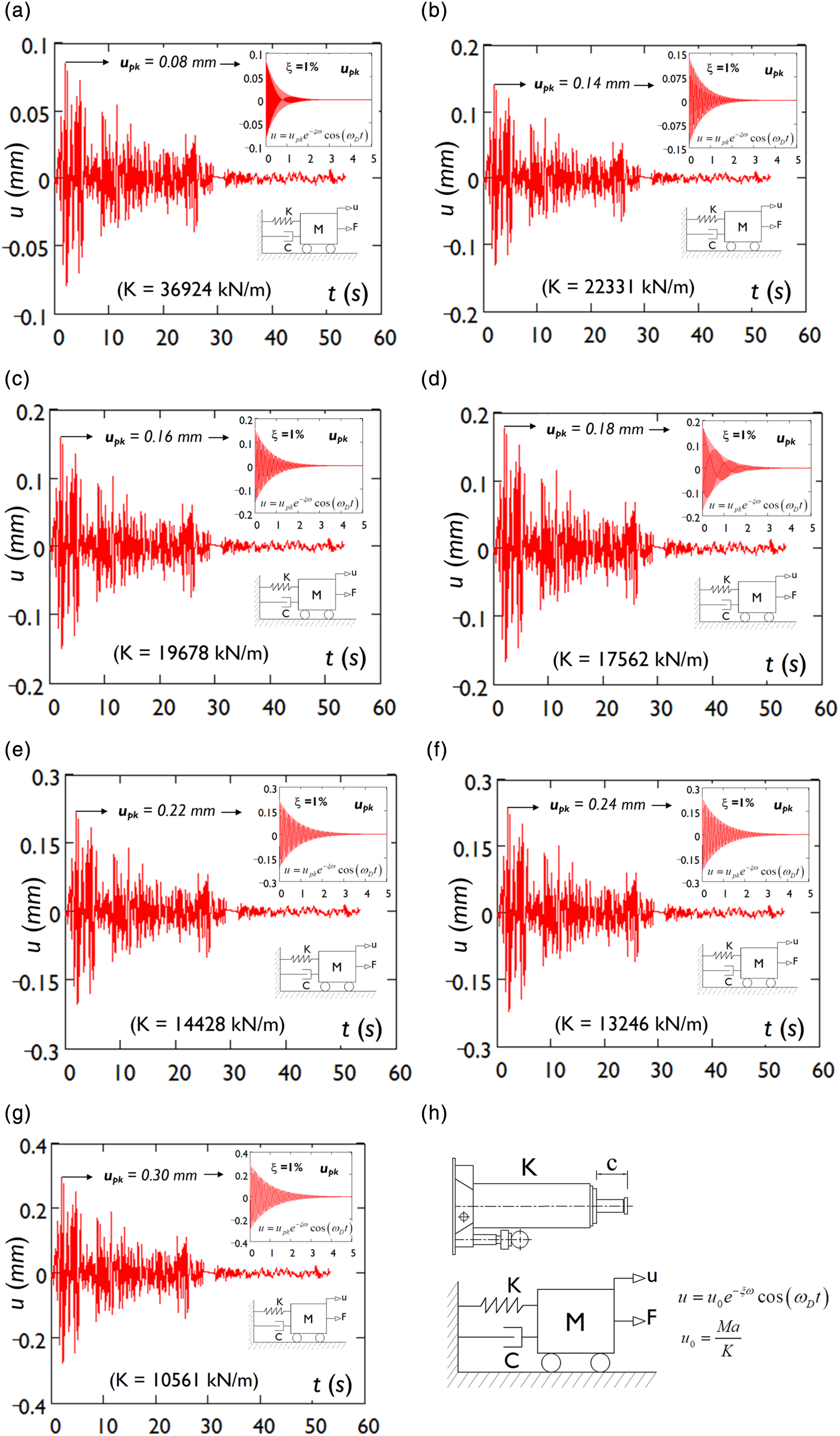
From the results presented here, it can be seen that when the stiffness is reduced by 71%, the frequency of the system decays by 47%, which follows from the increase in the cylinder height c. The higher and lower limits for the frequency are 46 Hz and 14 Hz, respectively.
The system response is shown in Figure 11 in regard to the inertial forces associated with the mass M and earthquake acceleration a, as found from equation (1) with u 0 (K) = Ma/K. The peak displacement u pk occurs at the peak acceleration a pk , and since (u pk (K) = Ma pk /K), the damped movement of the system can be obtained over the earthquake event. It is important to highlight that peak acceleration, peak velocity, and peak displacement are the most frequently used and best-known time-domain parameters in seismic engineering, 82 and are considered the most sensitive indicators when analyzing facilities subject to earthquakes. 83
Results for peak displacement.
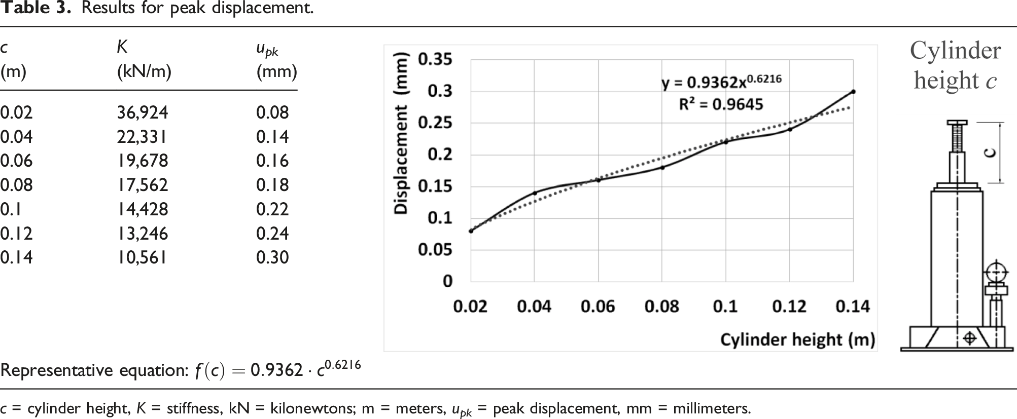
c = cylinder height, K = stiffness, kN = kilonewtons; m = meters, u pk = peak displacement, mm = millimeters.
For the parameters adopted here, such as the mass and damping ratio, the frequency of the SDOF system falls into the range of frequencies caused by the earthquake. This means that some type of resonance in the SDOF system could be produced by the earthquake. 84 Hence, the introduction of an apparatus which could control the displacements and modify the period of vibration would be important in terms of the safety and functionality of mechanical systems. 85
Natural frequency damping.
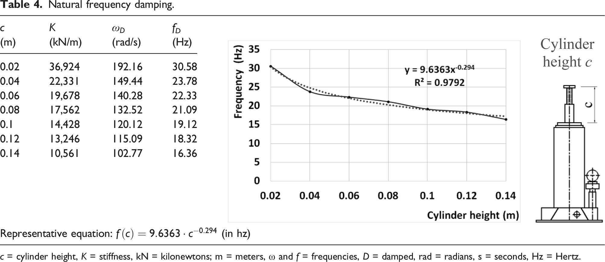
c = cylinder height, K = stiffness, kN = kilonewtons; m = meters, ω and f = frequencies, D = damped, rad = radians, s = seconds, Hz = Hertz.
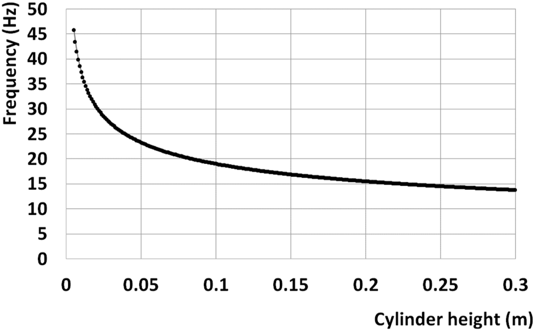
Frequency of variation with cylinder height.
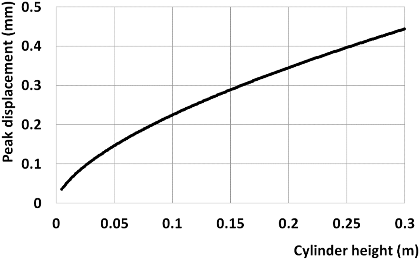
Peak displacement according to the representative equation.
It can be noted that Figure 7, Figure 12, and Figure 13, and their respective equations can be used in association with each other in order to find a specific cylinder height to meet a particular need. Hydraulic jacks can also be arranged in series to increase the equivalent stiffness, and can be applied to the diagonals of building frames to control the displacement. 86
Conclusions
In this study, an experiment was performed to determine the axial stiffness of a hydraulic bottle jack, with the aim of relating its behavior to that of a linear elastic element. The stiffness is an essential parameter that can be used to assess the effectiveness of the device in the field of vibration control. In this experiment, a uniaxial compression test using a manually controlled press was carried out. Seven positions for the cylinder elevation were adopted for its determination, with a quasi-static load. A numerical simulation of the field of vibration of the mechanical system was then conducted for a particular earthquake excitation.
Based on the obtained results, it can be concluded as follows: • The hypothesis of linear behavior was experimentally confirmed. For all of the cylinder elevation heights considered in the tests, the corresponding displacements were linearly proportional to the applied forces. In the same direction, the sustainable force had a linear relationship with the pressure generated inside the lifting chamber. • The stiffness coefficient was shown to have an inverse dependence on the height of the elevation cylinder. As the volume of the lifting chamber increases linearly with the height of the elevation cylinder, the spring coefficient is inversely proportional to it. For this reason, the axial stiffness depends on the height of the cylinder, as it determines the greater or lesser volume of oil in the compression chamber. • The stiffness coefficient was found to have distinct levels of magnitude. Factors such as the characteristics of the elevation chamber (which causes some compressibility of the oil), the tight of parts and components during the loading operation, the interaction between the components and the fluid, the adjustment of moving parts, and the deformation of solid components, may be associated with this result. • The frequencies were modified according to the experimental stiffness of the hydraulic jack in simulation. The results obtained for the free-damped vibration showed that the device investigated could be used as a tool for adjustment of the frequency. The simulation results indicated that the frequency varied inversely with the height of the elevation cylinder, following a power law with a negative exponent. • Displacement was reduced under seismic action. The stiffness of the hydraulic jack was shown to be capable of reducing the peak displacement of an idealized SDOF system. This is an important finding in terms of the safety and functionality of mechanical and structural systems. The results indicated that the displacement varied nonlinearly with the height of the elevation cylinder, following a power law with a positive exponent. • The results obtained here are valid when the hydraulic jack works in compression, but traction forces and cyclical loads were not investigated. In addition, using this equipment in a sloped or horizontal direction may not give the same results. • The hydraulic jack can be used with other jacks, and/or in combination with other devices. Since the equipment behaves as a translational spring, it can be used in a series or parallel arrangement to meet the needs of a specific application.
The main contribution of this work is that it was possible to demonstrate the possibility of representing a hydraulic bottle jack, a mechanical device whose operation is based on communicating vessels with numerous internal interactions, as a translational spring. With a knowledge of the main parameter related to this conception, the apparatus can find applications in relatively complex systems, including as a vibration control tool in dynamic problems and to mitigate the harmful effects of earthquakes.
Future work may include new experiments in which the jack is tested in horizontal and inclined positions. Hydraulic jacks subjected to traction forces and cyclical loading should also be investigated to widen the scope of this investigation. Buildings and other structural systems could be simulated based on the hypothesis presented here. Systems under periodic force and free vibration movement from an initial displacement could also be considered in future studies.
Footnotes
Declaration of conflicting interests
The authors declare no potential conflicts of interest with respect to the research, authorship, and/or publication of this article.
Funding
The author(s) disclosed receipt of the following financial support for the research, authorship, and/or publication of this article: This work was supported by the research relied on funding in the form of research scholarships from the National Council for Scientific and Technological Development (CNPq), the Foundation for Research Support of the State of Bahia (FAPESB), and the Coordination of Superior Level Staff Improvement (CAPES), all of them Brazilian agencies for supporting research.
Correction (March 2024):
The graphics used in Tables 3 and 4 were swapped, which has been corrected in the article now.