
Abstract
The field evaluation of pile-soil combination is a key step in the service life evaluation of pile foundation. However, due to the time-varying nature of pile-soil interaction, there is no efficient method to accurately analyze it. This paper introduces a health monitoring technique for assessing the state of pile-soil bond. The transient vibration of pile-soil coupling was measured by piezoelectric ceramic sensor. In the experiment, the different bond states of pile and soil were simulated by taking clay of different density as an example. A horizontal force is applied to the top of the pile, and the induced stress wave is detected by piezoelectric ceramic intelligent aggregate sensor embedded in the pile. At the same time, taking the artificial separation of pile-soil as an example, the binding state of pile-soil is analyzed, and the influence of different soil conditions on the pile-soil bonding characteristics is studied. An energy index for quantitative evaluation of pile-soil binding quality is proposed. Taking piles buried in two layers of soil with different densities as an example, the effects of soil with different densities on pile-soil bonding characteristics were studied. Experimental and numerical results verified the effectiveness of the proposed method. The three factors influenced the pile-soil coupling. The experimental and numerical results verified the effectiveness of the proposed approach and pave the way for an approach to directly judge whether there is separation between the pile and soil and evaluate the pile safety.
Introduction
Piles are widely used in weak soils as structural foundations. Quality inspection of pile foundation is an essential process in engineering construction. Although most pile foundations are based on the friction force between soil mass and pile body, in practical engineering, because soil is exposed to complex environment for a long time and under the action of external load, soil and pile will slip and break off. This results in an incomplete bond between soil and pile foundation. The pile-soil interaction exhibits complex and time-varying mechanisms, which has made soil-environment interaction a hot research topic nowadays. For example, Pak and Ji 1 studied rational mechanics of axial soil-pile interaction. Abedzadeh and Pak 2 investigated a cylindrical pile interaction with a transversely isotropic soil. Shahmohamadi et al. 3 studied the static axial soil-pile interaction in a cross-anisotropic medium. Among the research methods, dynamic-based tests are widely accepted. Chen et al. 4 studied the pile response under a transient torsional loading, while Ma et al. 5 investigated the dynamic torsional vibration of a pile in transversely isotropic saturated soil. Gómez et al. 6 studied the vibratory pile driving efficiency quantified energy flux. Prendergast et al. 7 investigated the Experimental application of model method of frequency response function in pile impact test. Tsetas et al. 8 studied the Experimental identification of dynamic characteristics of pile-soil systems installed by different piling techniques. For piles in a coastal region or ocean environment, chloride ion penetration also negatively impacts the pile structural integrity. 9 In practical engineering application, low and high strain integrity test method is widely used to evaluate the construction quality of pile foundation in civil engineering.10–12 The effects of dynamic loading or excavation unloading on p-y curves for laterally loaded piles have been studied to assess the pile properties.13,14 However, effectively solving the elastic wave equation is a challenging task when assessing pile safety Solving the elastic wave equation effectively remains a challenging issue for evaluating the safety of piles under complex soil interface conditions. It should be pointed out that there is no accurate monitoring method for in situ reaction at the real pile-soil contact surface. Currently, the existing means of monitoring and evaluating the pile-soil characteristics during service cannot directly measure the pile-soil interaction. Therefore, in order to effectively monitor the bond between pile foundation and soil in service state, it must be effectively controlled.
Structural health monitoring has gained increasing attention as a means to economically maintain infrastructure.15–17 Because of the specific working environment, pile inspection can be performed only via non-destructive testing methods. At the same time, it is also a difficult problem to monitor the status of pile body, so embedded piezoelectric transducer is used for monitoring.18–20 Owing to its low cost, fast response, solid state drive, implantable, and other characteristics, it has become a new type of actuators and sensors.21–24 A piezoceramic smart aggregate (SA) was introduced to protect the fragile piezoceramic transducer for applications in concrete structures. 25 Piezoceramic sensors have been used to detect damage of concrete structures,25–29 metal structures,30,31 composite structures,32,33 etc. In addition, Active sensing method has been applied to health monitoring of various civil buildings.34–36 However, to the best of our knowledge, extensive studies on monitoring and assessing pile-soil bonding have not been carried out.
In this study, a piezoceramic sensor–based impact approach is developed to monitor pile-soil bonding. The compactness of soil determines the shear wave velocity of soil with small deformation. 37 The shear coefficient of the soil can be obtained by using the shear wave velocity. The nonlinear interaction of soil-pile responding to a lateral load is closely related to the shear modulus of soil. 38 In this paper, a test hammer is used to apply lateral load on the top of the pile. In the experiment, the interaction between soil and pile foundation was investigated by changing the density of soil. An energy index is proposed to quantitatively evaluate the pile-soil coupling. The induced stress waves were detected by SA sensors embedded in the pile. The SA sensors at different locations of the pile show different responses, which reflect the locations restricted by soils with different densities. In this paper, we propose a health monitoring approach to evaluate the bonding status of the soil and pile. To investigate the effectiveness of the proposed method, an artificial separation between the soil and pile was introduced as slippage. Meanwhile, a different test was carried out to investigate the pile-soil coupling behavior in a nonhomogeneous soil, with a pile surrounded by two soil layers. To verify the results obtained in the experiments, a numerical simulation was carried out using the finite element program ABAQUS. The numerical calculation provides a basis for further study of the bearing capacity of a single pile. The research results of this project will provide a theoretical basis for non-destructive testing of piles in practical engineering.
Monitoring principle and algorithm
Principle of the horizontal impact response using SA sensors for an analysis of the pile-soil bonding
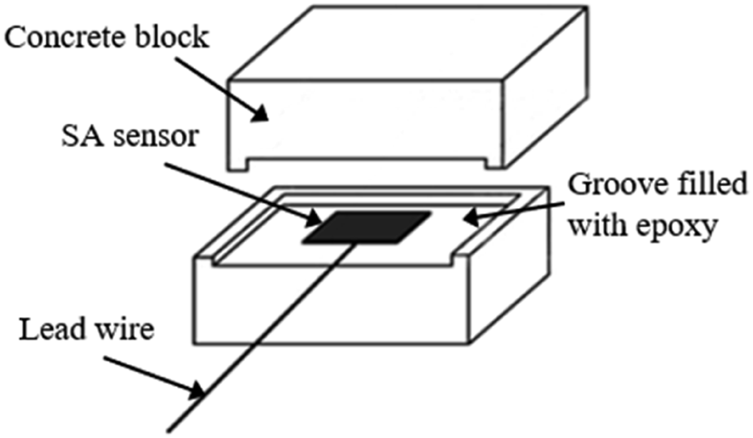
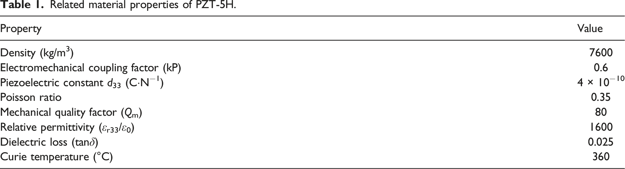
Lead zirconate titanate (PZT) is one of the commonly used piezoelectric materials that can generate an electric charge under a mechanical stress (direct effect) and, conversely, mechanical strain in response to an applied electric field (converse effect). The induced voltage is proportional to the dynamic stress on a blocked PZT sensor.39,40 The SA shown in Figure 1 employs a PZT patch. The detailed construction of the SA is shown in Figure 2. The material type of the PZT is PZT-5H, which is highly sensitive to dynamic excitations. Table 1 shows the related parameters of PZT-5H. The dimensions of the PZT patch are 10 mm × 10 mm × 0.3 mm. The SA sensor is embedded in the concrete, and the structure has good mechanical stability. PZT sensors are widely used to detect signals containing high frequency components because of their high bandwidth and piezoelectric effect,41–43 such as ultrasonic waves44–47 and shock- or impact-induced stress waves.48–51 To solve the problem of unclear failure mechanism of pile-soil interface bond, a new dynamic collision detection technology is proposed in this paper to detect the failure of pile-soil interface bond. SA with a signal connector. Detailed structure of the SA. Related material properties of PZT-5H.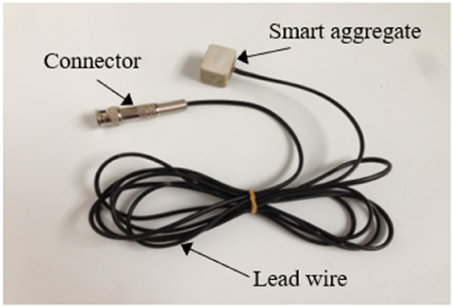
The density of soil is typically one of the most critical factors affecting its strength and stiffness. Mechanical properties of soil tend to vary based on its density. For instance, compacting the soil can increase its density and subsequently improve the bonding between the soil and pile, which is a common method to enhance the loading capacity of the pile. The principle underlying this approach is that, for the same type of soil, its strength generally increases as its density increases. Moreover, the stiffness of the soil surrounding the pile, which provides boundary strained conditions for the pile, varies depending on the degree of bonding between the soil and pile. Typically, a denser soil provides stronger bonding for the pile. Different densities of soil also exhibit varying properties when it comes to wave propagation, which means that bonding monitoring can be performed by analyzing the wave responses across the pile-soil contact area under different soil densities.
As shown in Figure 3(a), on the top of reinforced concrete test pile, a horizontal vibration hammer is used as transient impact actuator and SA is used as sensor to detect its response, and SAs were used as sensors to detect the response. To fix the SAs during the pouring of concrete, they were attached to the nearby steel rod with an epoxy. The cross section of the test pile is shown in Figure 3(b). Owing to the effect of gravity, the stress applied on the pile is different along the height, which induces quite different boundary restraints on the pile, and thus the response of the SA sensor wave signal changes with its location along the pile. According to the PZT electric-mechanical effect relationship, when the severity of the soil constraint on the SA sensor is larger, the PZT mechanical performance is more restrained, and the SA sensor response signal is weaker. The bonding status of the pile by soil can be evaluated by analyzing the response signals. (a) Diagram of the transient impact response evaluated using SA sensors. (b) Cross section of the pile in (a) (unit: cm).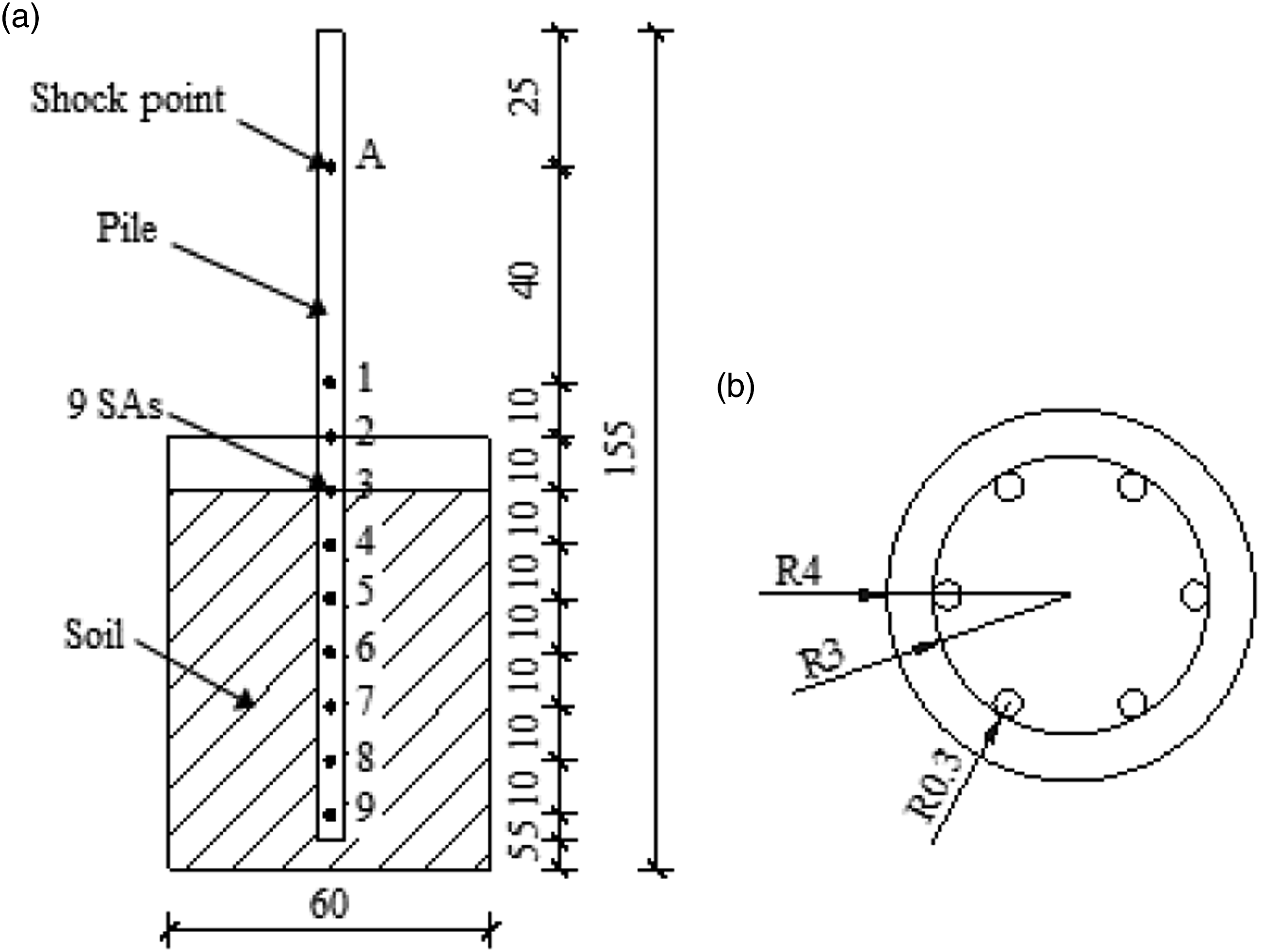
Basic principles of the time-domain analysis
The propagation of the test wave signal between the pile and soil is sensitive to the degree of bonding between the pile and soil, the vibration frequency between pile and soil is closely related to the binding strength of pile and soil. In this study, a time-domain analysis is carried out to study the signal received by the sensor. The energy of the signals is calculated to measure the degree of bonding. In the proposed health monitoring algorithm, a signal energy index E i is defined as follows.
We use X
i
to represent a set of discrete data of a signal obtained by the sensor in given sampling duration at time i. X
ij
is the sensor voltage of the jth sampling point at time i. A total of m sampling points contribute to the calculation in each sampling duration. 
In order to monitor the cohesive force between pile and soil, the energy index is defined as
Experimental setup and testing procedure transducer
Experimental setup
The testing soil was filled in a box with dimensions of 500 mm (length) × 450 mm (width) × 800 mm (height). A 1500 mm long reinforced concrete pile with a cross-sectional radius of 4 cm was buried in the soil, as depicted in Figure 3(a) and (b). The testing soil was clay, as shown in Figure 4, with very delicate and close particle sizes; 50% of the grain sizes were smaller than 0.075 mm. The experiment system is shown in Figure 5(a). A signal acquisition system is selected to record the signal. The sampling frequency and recording time were 7160 Hz and 0.15 s, respectively. A total of nine SAs, as sensors to receive the real-time signal, were embedded in the pile with an interval of 10 cm. The location of each SA sensor in the pile is shown in Figure 3(a) and 5(b). A hammer was used to apply a horizontal transient impact to the pile, with the controlled impact location being determined from the ruler that was bonded to the top surface, as depicted in Figure 5(c). During transverse vibration, the interaction between the pile and foundation becomes apparent, which results in the SA sensor signals being different in the longitudinal direction. Therefore, changes in these signals can be utilized to assess the pile foundation and soil combination. To analyze the strength of the pile-soil bond, three examples were examined. Soil specimen used in the experiment. Experimental setup. (a) Transient impact response experiment system. (b) Distribution of SAs in the pile. (c) A horizontal transient impact was applied by a hammer, and the tamping height was measured by a ruler.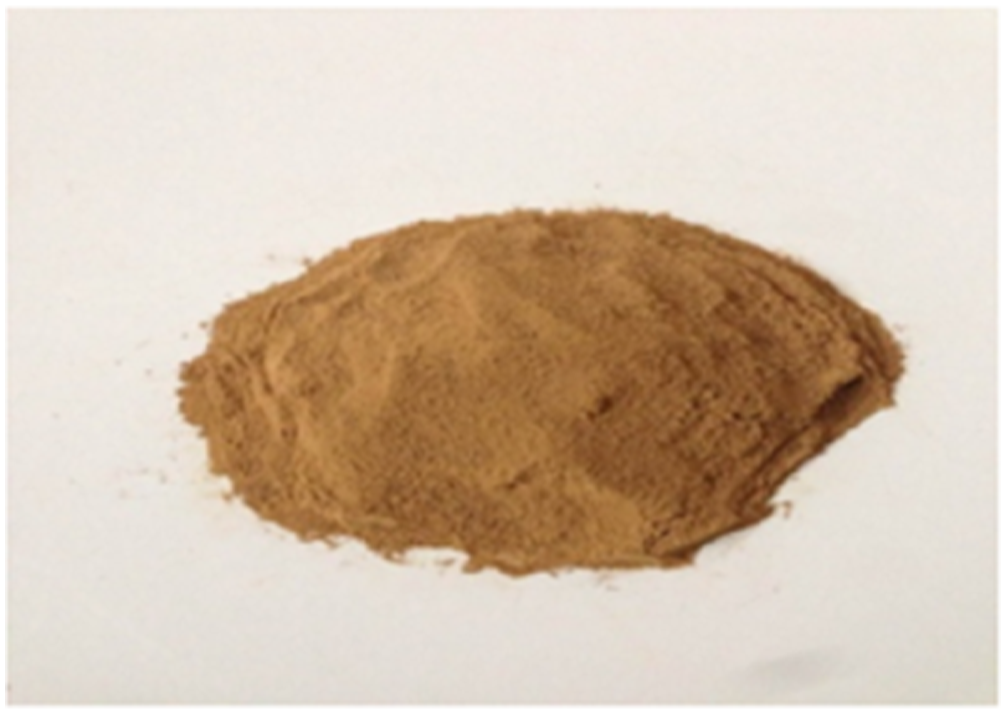
Testing procedures
Soil preparation
Three different mass densities of soil were used for the experiment. The basic soil is clay with 50% of the grain sizes smaller than 0.075 mm, with the same moisture contents, as shown in Figure 4. Through compacting on the soil, we obtained three specimens of testing soils with mass densities of 1318, 1491, and 1588 kg/m3.
Three test cases for an analysis of the coupling degree between the pile and soil
A soil with a higher density has a higher compactness, which provides a larger constraint on the pile, resulting in a better pile-soil bonding. Soils with three different densities of 1318, 1491, and 1588 kg/m3 were used as testing soils in the box to investigate the SA sensor response to evaluate the influence of the soil compactness on the pile-soil bonding.
In the soil with the density of 1491 kg/m3, a gap between the pile and soil with a depth of 20 cm from the surface of the soil was artificially created to simulate the separation between the pile and soil. In this case, we intended to investigate the SA sensor signal changes in comparison to that without damage on the pile-soil contact area and study whether the SA sensor can reflect the incomplete bond relationship between pile and soil.
Two layers of soil were set into the testing box where the bottom layer had a higher density than that of the top layer to simulate the natural soil with different layers.
In each case, the horizontal vibration was caused by the hammer hitting the top of the test pile. To make a fair comparison, we should retain the initial instantaneous shock wave energy based on the initial value. Therefore, the hammers all release freely at the same height. This was controlled using an installed ruler, as shown in Figure 5(c). When the hammer struck on the pile actuating the initial signal, SA sensors began to response to the impact. Response variations among SA sensors could reflect the bonding differences. SA sensor response signals were recorded by a data acquisition system, as shown in Figure 5(a).
Experimental results and analyses
Case 1: Effect of the soil compactness on the pile-soil coupling
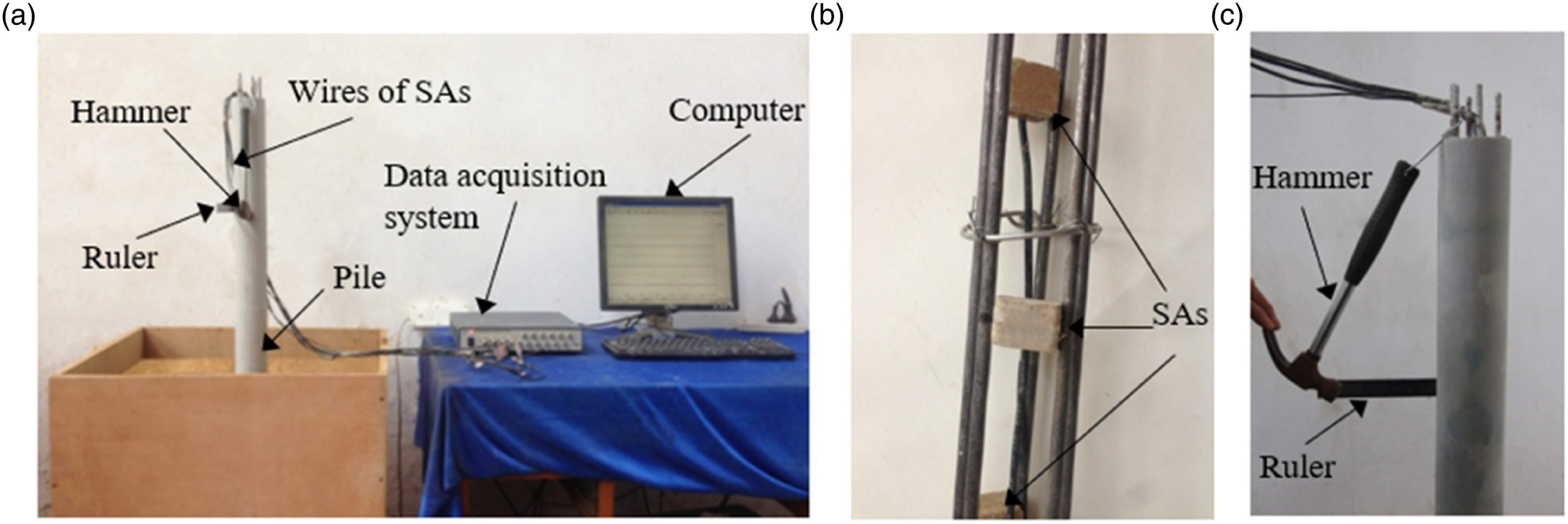
The soil with a higher density can provide a better pile-soil bonding because of its higher compactness. In the test, the matrix density of soil is generally high because of gravity. In practical application, different soil layers have different constraints on pile. In the deeper soil layer, the bond between pile and soil is better. A better pile-soil bonding develops along the soil depth. Thus, the signal responses obtained by the SA sensors would be different along the pile for different pile-soil bonding degrees. Therefore, when the soil constraint on the concrete pile is larger, the mechanical deformation of the SA sensor resulting from the transient impact is weaker, and thus the electric response signal of the SA sensor is weaker. Owing to its better transmission performance, the signal wave could last for a short time in a high-density soil. Owing to the same reason, in comparison to the low-density soil, the wave energy indicator of the SA sensor in the high-density soil was smaller. As illustrated in Figure 6(a) to (c), for all soils with densities of 1318, 1491, and 1588 kg/m3, the constraint force on the SA sensor considerably increased with the depth of the SA sensor. Signals recorded by SA sensors in soils with different densities of (a) 1318, (b) 1491, and (c) 1588 kg/m3.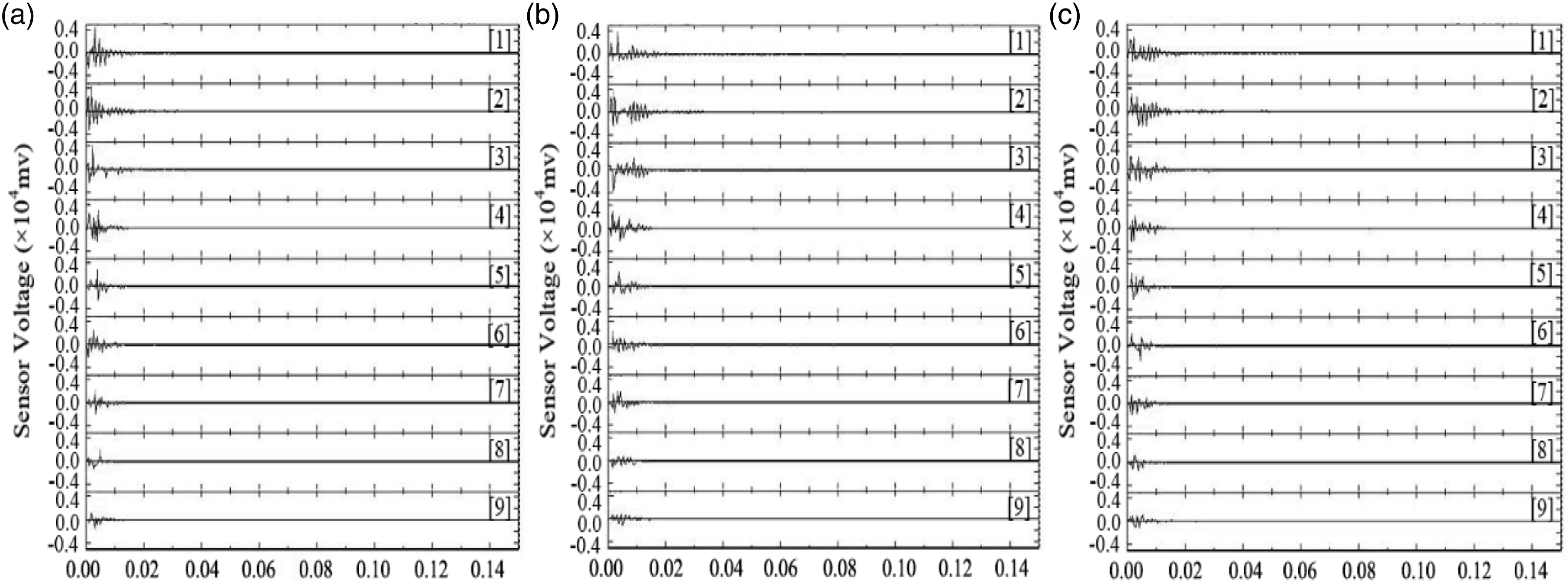
The signal strength of the bottommost ninth SA sensor was weaker and had a shorter duration compared to the upper sensors due to the better bonding between the pile and soil. Conversely, the uppermost first SA sensor had a strong signal that lasted longer. To prevent signal propagation loss in the pile from affecting the experimental results, the pile was placed on a level floor before being buried in the soil. After hitting the pile with a hammer, the signal amplitudes of the ninth SA recorded by the signal receiver were nearly identical. Therefore, we did not take into account the energy attenuation caused by signal propagation in this investigation.
As shown in Figure 7(a), SA sensors are able to transmit more wave energy to the soil as soils with higher density tend to load more dense constraints. Therefore, signal amplitudes recorded by SA sensors decrease with the increase of soil density. The mechanical deformation of SA sensor is small under larger constraints. The sensor voltage is proportional to the dynamic stress on the SA sensor,39,40 so the signal amplitude recorded by the SA sensor can be used to feedback the constraint effect on the SA sensor. (a) Amplitudes and (b) energy indicators of the signals presented in Figure 6(a) to (c).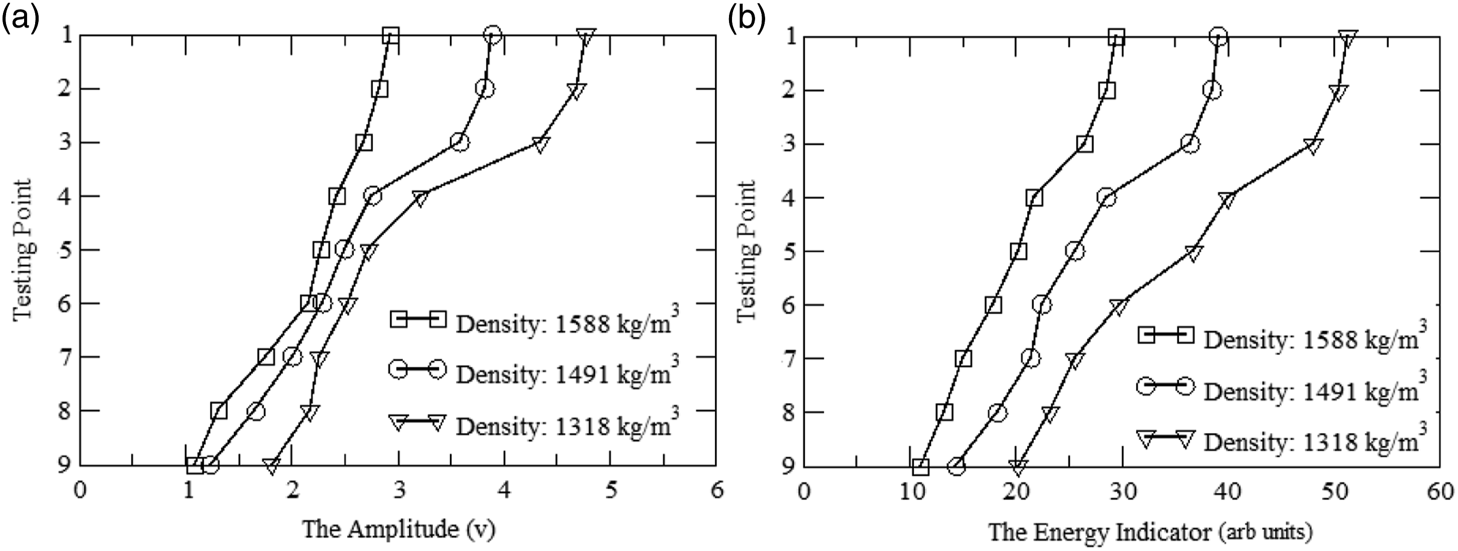
The severity of the pile-soil coupling can be expressed by the energy indicator (equation (2)). Upon the horizontal transient impact, the SA sensors responded to the vibration, 40 and then the stress wave propagated from the SA sensors into the soil. Usually, in the soil with a high density, the soil compactness is also high, usually with less pores in the soil. Less pores in the soil led to less scattering in the propagation,52,53 which enabled a better transmission performance. In such a case, more wave energy can be transmitted into the soil because of the better bonding between the pile and soil, 52 and a small amount of energy is left in the pile as detected by the SA sensors embedded in the deep soil, as shown in Figure 7(b).
The numerical value of the horizontal force is calculated to obtain the stress distribution of the pile. As the mass of the hammer is 0.34 kg and the length of a single pendulum is 23 cm, the horizontal force F applied on the pile was obtained (F = 22.7 N) using the single-pendulum theory. A finite-element model was then developed in ABAQUS. The cuboid was divided into 18 elements along the length and width directions and 22 elements along the height direction, as presented in Figure 8(a). The model, which simulated the reinforced concrete pile, was divided into 48 elements on the cross section and 86 elements along the height direction. The model considered the pile as an elastic material and soil as a Drucker-Prager (D-P) material. A solid element was used to simulate the soil and pile. The basic soil parameters were an elasticity modulus, Poisson ratio, density, and cohesion force of 0.26 GPa, 0.42, 1436 kg/m3, and 19 kPa, respectively, while the soil friction angle and dilatancy angle were 31° and 29°, respectively. The elasticity modulus, Poisson ratio, and density of the steel bar were 210 GPa, 0.3, and 7850 kg/m3, respectively. The stress distribution of the pile was different with the variation in the soil density, which is reflected in the three stress nephograms in Figure 8(c) to (e). When subjected to a horizontal load with equivalent transient impact characteristics as the experiment, the stress exerted on the pile body experiences a sharp change in response to the depth at which it is buried. As depicted in Figure 7(a) and 8(b), the signal amplitude decreases progressively as the stress levels increase. Finite-element simulation for soils with different densities. (a) Mesh model of the numerical simulation. (b) Stress of the bonding area between the pile and soil. Stress nephograms of the bonding areas in the soils with different densities of (c) 1318, (d) 1491, and (e) 1588 kg/m3 (unit: MPa).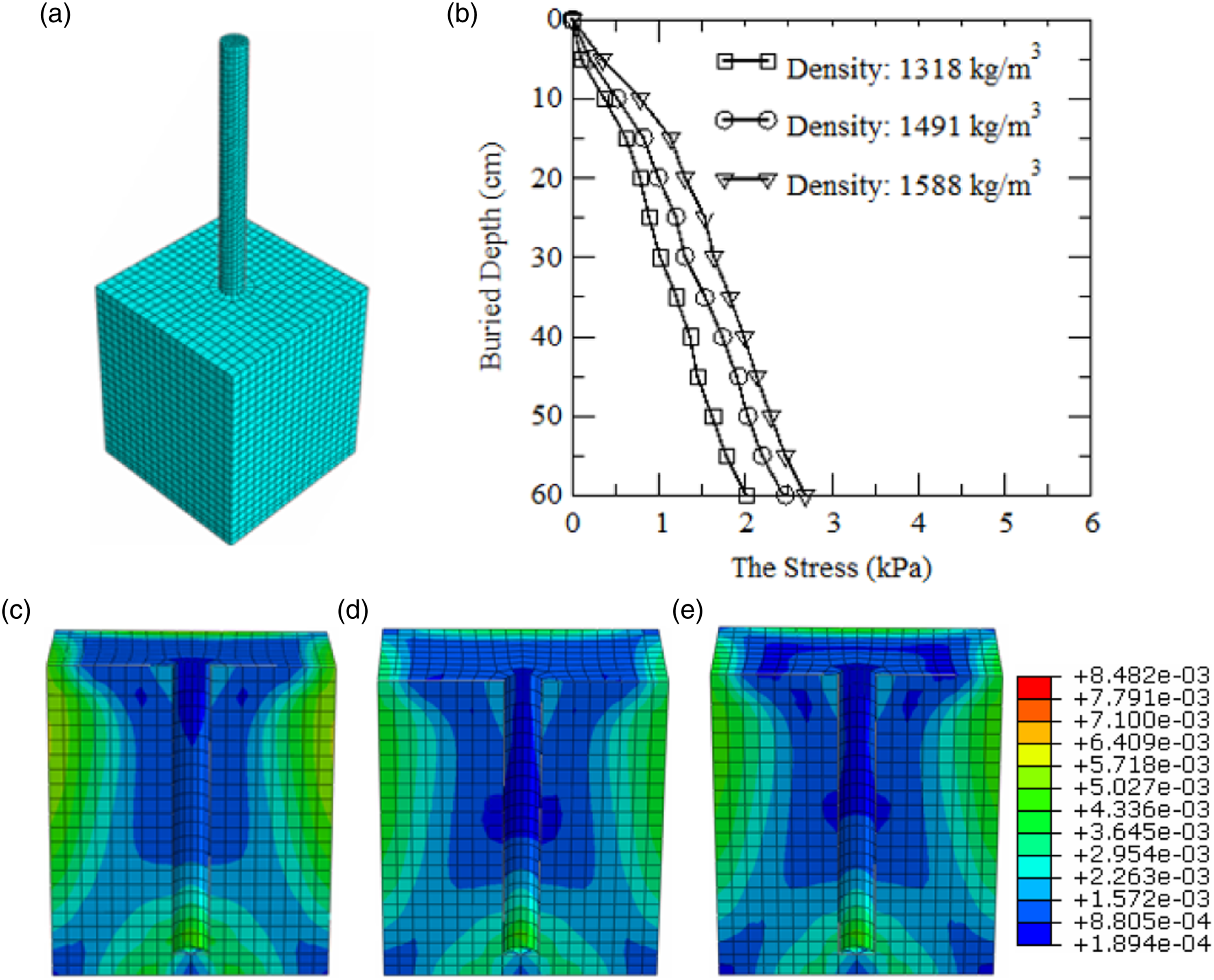
Case 2: Separation damage effect on the pile-soil coupling
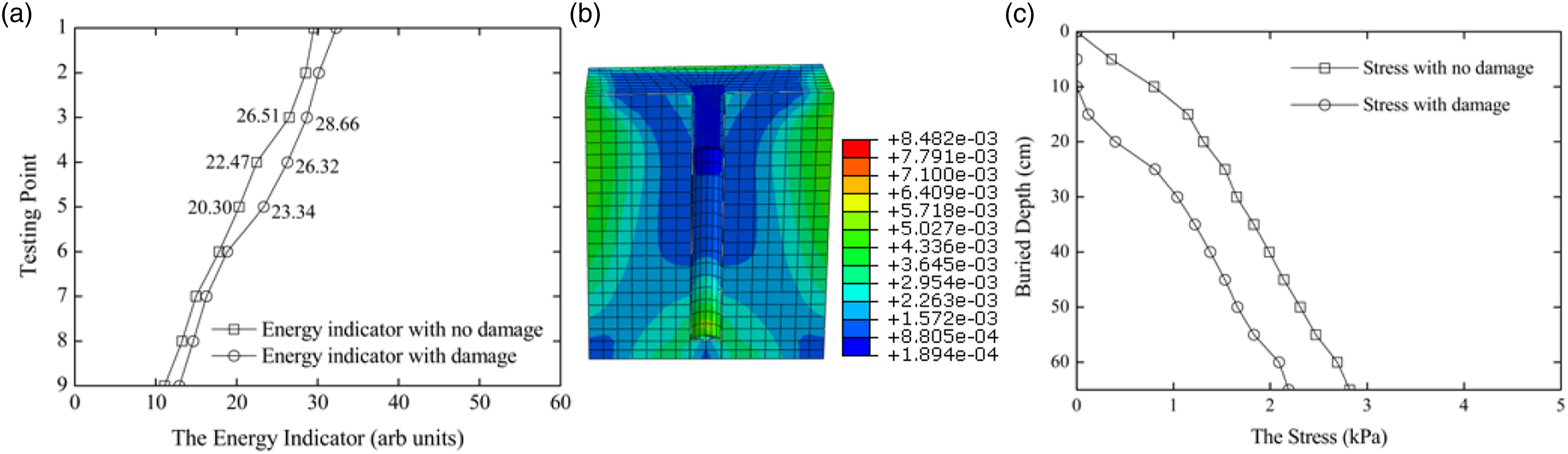
To simulate the slippage effect between the pile and soil, an artificial separation damage with a width of 2 cm and depth of 20 cm was introduced on one side of the contact area of the pile and soil, as shown in Figure 9(a). The density of the soil was 1436 kg/m3. The amplitude of the signal decreases with the increase in the buried depth of the SA sensor, as shown in Figure 9(b). To study the separation effect, signals recorded before and after the introduction of the separation damage are compared, as shown in Figure 9(c). With the separation damage between the pile and soil, the amplitudes of the signals recorded by SA-3, SA-4, and SA-5 are considerably larger than those without separation as the soil constraints on these three SAs were largely reduced after the separation damage. Because the limitation degree of the three SAs after damage treatment is greatly reduced, the measured signal amplitude is larger than that without damage treatment. When there is no damage or separation between the pile and its foundation, the force deformation of the soil around the pile (SA) is greater than that of the pile body under the same transient load. To put it simply, the deformation of the soil around the pile is more significant than the deformation of the pile itself when there is no damage or separation between the two. The voltage of the sensor is directly proportional to the pressure39,40 applied to the SA. After separation damage, the amplitudes of the three SA signals were enhanced. After recording the damage, the data obtained by the three SAs were significantly higher than that obtained by the SAS without introducing damage. Because separation damage reduces the coupling degree between pile-soil, less energy is transferred through the pile-soil interface during the loss process. The attenuation table of wave energy in SA-3, SA-4, and SA-5 is shown in Figure 10(a). In Figure 10(b), finite element simulation is carried out on the stress of separated damaged pile. In Figure 10(c), the pressure d of pile decreases compared with that of pile without separation damage. Figure 9(c) and 10 show that the increasing amplitude of the signals with separation damage can be attributed to the improvement in the pile’s stress. Separation damage effect on the pile-soil bonding. (a) Separation damage illustration (unit: cm). (b) SA signals in the soil with the separation damage. (c) Signals recorded by SA-3, SA-4, and SA-5 with separation damage, compared to those without separation damage. Finite-element simulation for the separation damage effect on the pile-soil coupling. (a) Energy indicator with and without damage. (b) Stress nephograms of the bonding area (unit: MPa). (c) Stress of the pile-soil contact area with and without damage.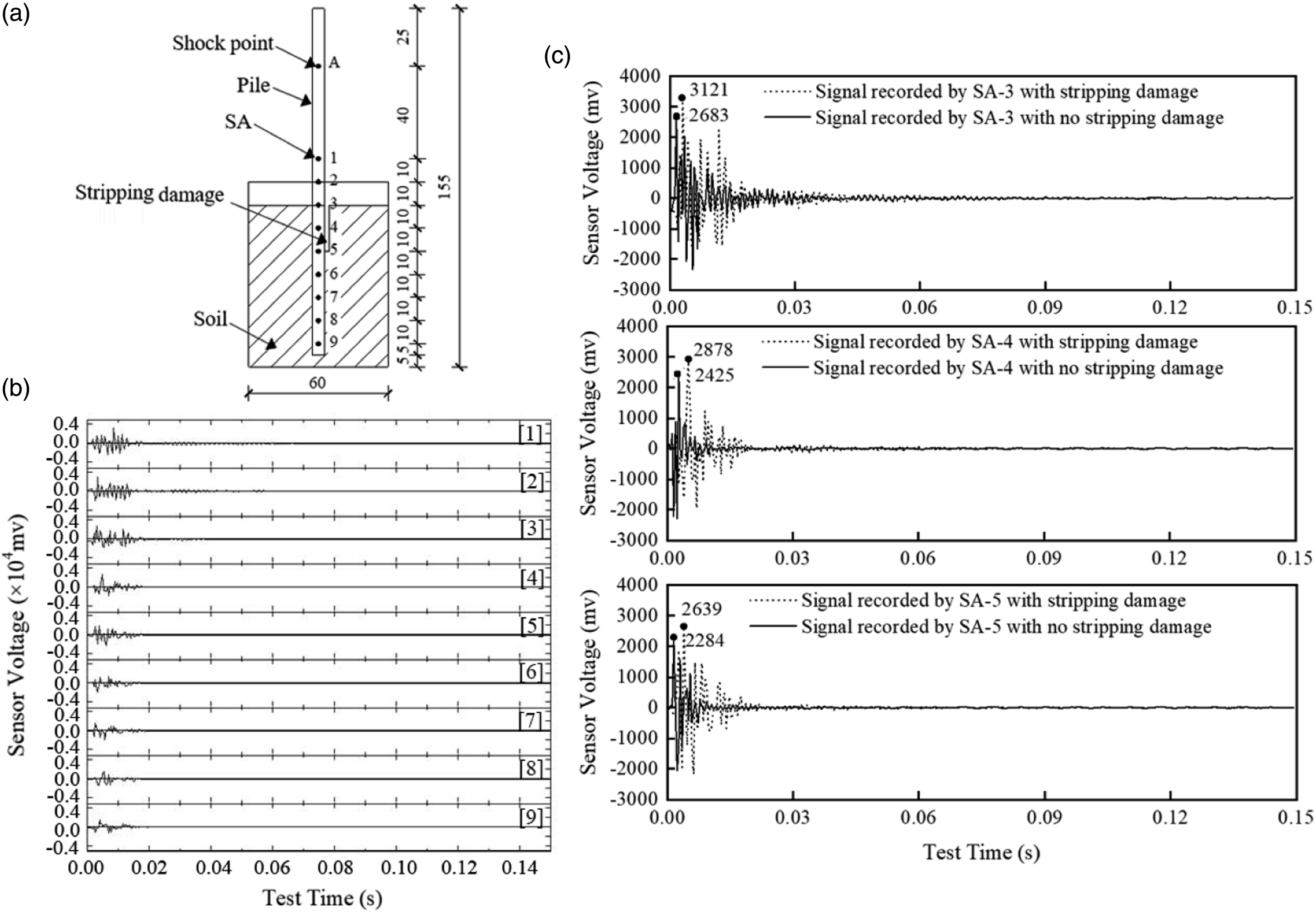
Case 3: Effect of the soil layers on the pile-soil coupling
In practice, the soil body is established layer by layer of various soils with different mechanical properties in the nature, their physical characteristics are also different. A pile is always embedded in a few layers of soil along its height. Usually, these various layers of soil contribute with different constraint effects on the pile-soil contact area. To study the soil layer distribution effect on the pile-soil coupling, two layers of soil were set into the test box, as shown in Figure 11(a). The bottom layer density was 1588 kg/m3, while that of the top layer was 1318 kg/m3. Two-layer soil case study. (a) Two layers of soil are filled in the test box (unit: cm). (b) Signals recorded by the nine SAs, buried at the locations corresponding to the solid circles marked on the pile in (a). The curves marked by hollow circles in (c) and (d) show the amplitudes and energy indicators of the SA signals recorded in (b), respectively. The amplitude and energy indicator in the case of Figure 6(a) (or Figure 6(c)) are also included for comparison, as shown by the curves marked by hollow triangles (or squares) in (c) and (d). (e) Stress nephogram of the bonding area in the soil with two layers (unit: MPa). (f) In the soil with two layers, the dependence of the stress in the bonding area on the buried depth is shown by the curve marked by hollow circles in (f). The stress in the case of Figure 8(c) and (e) is also included for comparison, as shown by the curves marked by hollow triangles and squares in (f).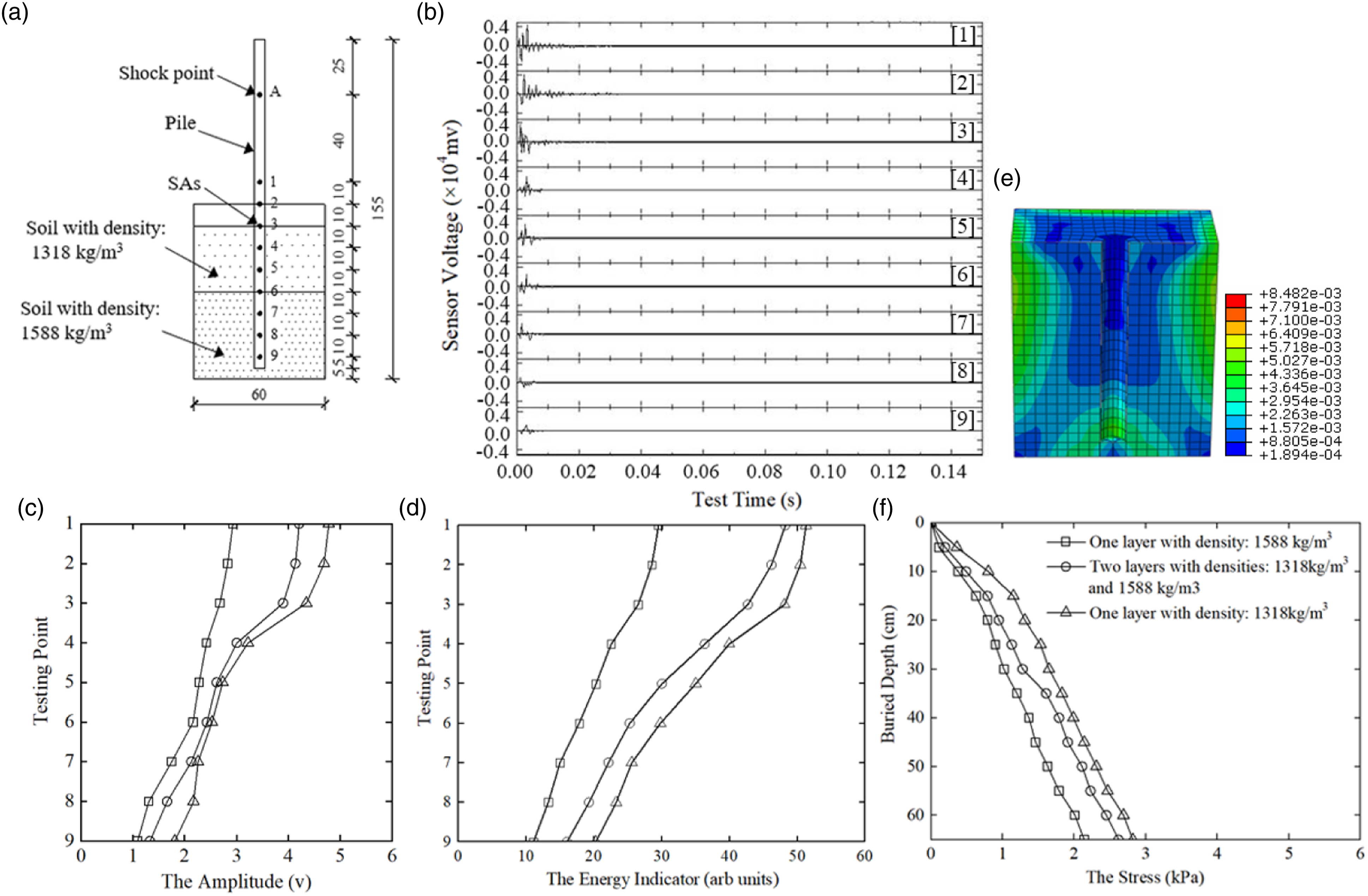
The mechanical properties of each layer of soil differ greatly due to differences in compactness, resulting in varying constraint effects on the pile. Consequently, SA sensors in piles buried in different soil layers exhibit different responses to transient shocks. Figure 11(b) shows the signals recorded by the signal receivers of the nine SAs, where the amplitudes of SAs in the top layer with a lower density are higher than those in the bottom compact layer with a higher density, as the degree of pile-soil bonding varies along the soil layers with different densities. The amplitude of the signal recorded by SA sensors in the two-layer-soil case, as shown in Figure 11(c), was larger than that of only one layer with a density of 1588 kg/m3 and smaller than that of only one layer with a density of 1318 kg/m3. This can be explained as the constraint on the SA sensors in the two-layer soil being larger than that of only one layer of soil with a higher density and smaller than that of only one layer of soil with a smaller density. As mentioned, the sensor voltage decreases with the constraint intensity. The energy indicator of the signal recorded by SA sensors embedded in the soil with two layers has the same behavior as that of the amplitudes, as illustrated in Figure 11(d).
A positive correlation between the variation in wave energy and soil compactness can be established due to the energy lost during wave propagation through the interface area of the pile-soil. As a result, a compact layer of the same soil type can easily transmit more wave energy into the soil while leaving less energy within the pile, as indicated by the SA sensor. A numerical simulation is performed in ABAQUS to verify the experimental results of this test case. The stress distribution in the bonding area was computed; the result is presented in Figure 11(e). The stress in the bonding area is larger than that of only one layer with a density of 1318 kg/m3 and smaller than that of only one layer with a density of 1588 kg/m3, as shown in Figure 11(f). The distribution of the stress verifies that the constraint on the SAs increases with the buried depth. In addition, Figure 11(c), (d), and (f) show a negative correlation between the amplitude or energy indicator of the signal and stress distribution of the bonding area.
Conclusions and future studies
To monitor pile-soil bonding conditions, an innovative approach based on transient impact response using embedded SA sensors is proposed. According to the three case studies, the signals recorded by the distributed SAs along the height of the pile responded to the transient impact applied on the top of the pile. The wave signals varied with the sensor location and soil density. The findings of this study obtained through experimental and numerical analyses can be summarized as follows. 1. For the same type of soil, the amplitude of signal detected by SA sensor decreases with the increase of soil density, as the soil with a higher density always provided a better constraint on the pile and better pile-soil bonding, resulting in more wave energy leaking into the soil and weaker sensor signal. 2. Damages on the pile-soil interface, such as slippage or separation, could be detected by the SA sensor responses by comparison to data in the case without damage. The case study inspires an approach to determine whether the bonding between the pile and soil fails. 3. The piezoelectric ceramic sensor signals of different density soil layers are different. By comparing the signals collected by different density soil layers, the density detection of a specific soil layer can be realized. 4. In all three cases, the results of the numerical simulation demonstrated that as the depth of burial increased, the stress also increased, resulting in a stronger bond between the pile and the soil. However, this improved bonding also resulted in a decrease in the amplitude of the piezoceramic sensor signal. These simulation outcomes serve to aid in the analysis of the p-y curves of the soil.
In a future study, we intend to implement the proposed method to an in-service pile and provide monitoring and assessment of the pile-soil coupling during the life cycle. In addition, we intend to investigate the modeling of stress wave propagation through the pile-soil interface using the fractal contact theory. 50
Footnotes
Declaration of conflicting interests
The author(s) declared no potential conflicts of interest with respect to the research, authorship, and/or publication of this article.
Funding
The author(s) disclosed receipt of the following financial support for the research, authorship, and/or publication of this article: The authors acknowledge financial support from the Key Program of the National Natural Science Foundation of China (Grant No. 52239009), the Research Project for High-Level Talents from the Jiangxi University of Science and Technology (Grant No. jxncbs19009) and the Science and Technology Project of Gansu Provincial Department of Housing and Urban-Rural Development (Grant No. JK2023-26).