
Abstract
Vibration and noise pollution is one of the main pollution in modern society. In order to obtain good vibration damping effect, more effective phononic crystals should be designed. Based on the theory of elastic wave propagation in solids, three types of phononic crystals are designed in this paper using tungsten blocks embedded in a rubber matrix, which are cup-shaped phononic crystal, solid cylindrical phononic crystal, and hollow cylindrical phononic crystal. Firstly, the band gap characteristics and vibration losses of the three phononic crystals are analyzed by using the finite element method. Secondly, the physical mechanism of band gap formation is explored by vibration modes. Finally, the cup-shaped phononic crystal was introduced into the core layer of the sandwich plate to form the cup-shaped phononic crystal sandwich plate, and its vibration damping performance was analyzed. The results show that the three phononic crystals can form three band gaps in the range of 0–800 Hz, and the first low-frequency band gap starts at about 140 Hz and is all wider than 200 Hz. It is noteworthy that the average loss of vibration transmission of the three types of phononic crystals is more than 69 dB, which possesses stronger damping capability and wider low- and middle-frequency band gaps than the flat plate type phononic crystals. The vibration direction of the phononic crystal is at an angle of 90° to the wave vector, which prevents the propagation of elastic waves. The phononic crystal embedded in the sandwich panel plate is more in line with the actual demand of vibration damping and obtains good vibration damping effect. The research in this paper can provide more feasibility for phononic crystal damping.
Introduction
Vibration and noise widely affect people’s lives. Vehicles, ships, and other types of construction machinery exposed to vibration for a long time will shorten their service life.1,2 Meanwhile, the body of a conveyance (car, plane, and train) consists mainly of thin-walled panels. These panels and acoustic interiors resonate significantly resulting in poor sound insulation performance of the body. Considering the body size and weight, the thickness of sound insulation components is usually required to be less than 5 mm. This goal poses a challenge for sound insulation design. Therefore, solutions to reduce the vibration and noise of the structure are urgently required. As an important research topic in the field of sound and vibration control, plate and shell structures have already made great progress in vibration and noise reduction.3,4,5,6,7,8 To improve the sound insulation of sandwich plate structures, the incorporation of micro-holes3,4,5 using the Helmholtz resonance mechanism or the employment of phononic crystals with bandgap characteristics 6 has been studied. Specifically, Filho et al. 7 employed a hook-like mass vibrator on a foam sandwich panel, successfully improving the sound insulation performance of the sandwich structure due to the “mass-spring-mass” resonance. Moreover, Ampatzidis et al. 8 introduced phononic crystals into the inner core of a sandwich plate to increase the vibration loss performance. Both the experimental and simulation structures show that the frequency response has a low curve in the forbidden band. However, research thus far has been largely limited to the mid-frequency (300Hz–2500 Hz) and high-frequency range (2500Hz–20,000 Hz), which is of little significance for low-frequency (20Hz–300 Hz) sound insulation and vibration reduction. Especially for low-frequency elastic waves, due to the long wavelength, strong propagation ability and inherent characteristics of difficult attenuation, 1 there is an urgent need to explore new structures and new materials to meet the vibration reduction requirements.
Phononic crystals are an excellent sound insulation material, which has the forbidden band characteristics of lossy elastic waves. 9 Assouar et al. 10 and Zhou et al. 11 embedded solid masses made of soft and hard materials layered on an aluminum plate for which both could obtain a lower frequency bandgap. Recently, Yang et al. 12 designed a tapered scatterer phononic crystal wrapped in rubber on a resin plate to obtain a complete low-bandwidth bandgap of 100–700 Hz. Its 10 mm structure, however, is difficult to process in practice. In addition, relevant studies mainly focus on the analysis of the bandgap12,13,14 and the vibration reduction performance of the structure13,14,15 under ideal conditions. A more classic method was applied in Ref, 13 which introduced cantilever beams and mass blocks inside the splint and took advantage of the bandgap characteristics to improve the damping capacity of the sandwich plate. Compared with only adding sandwich plate on the upper and lower surfaces of the phononic crystals, 8 the control mechanism is more complicated, but the different approaches are the same. It can be seen that a structure that not only meets the needs of engineering low-frequency vibration reduction but can also be easily employed is yet to be achieved.
In order to solve the above problems, in this paper, three types of phononic crystals by embedding metallic tungsten in rubber are proposed, which are cup-shaped phononic crystal, solid cylindrical phononic crystal, and hollow cylindrical phononic crystal, and their energy band structures and vibration damping properties are analyzed and compared with those of flat phononic crystals. Firstly, the bandgap characteristics and transmission loss performance of the three phononic crystals and control group are calculated by the finite element method (FEM) based on the elastic wave periodicity theory. Secondly, the vibration modes are used to explain the formation mechanism of the bandgap. Thirdly, the vibration damping performance of the traditional pure sandwich panel and the sandwich panels of cup-shaped phononic crystals is compared. Finally, some important conclusions will be formed.
Model and materials
Viscoelastic rubber as a matrix material is often used for sound absorption because of the ease of impedance matching and the large damping loss of viscoelastic rubber, especially for transverse waves. During the absorption of incident acoustic waves, most of the longitudinal waves entering the rubber are converted into transverse waves by wave mode conversion (when a longitudinal wave hits a solid interface at an angle, some of the energy can cause particle movement in the transverse direction. The longitudinal wave is mode converting to a transverse wave, following Snell’s law. This mode conversion occurs because the wave encounters an interface between materials of different acoustic impedances and the incident angle is not normal to the interface), which further improves the sound energy loss in the matrix material. The common method is to add metal powder or different cavities to the rubber to cause shear deformation of the incident longitudinal wave along the interface. Therefore, the flexible design and the combination of cavities and metal fillers are the key to improve the sound absorption characteristics and the starting point of this study.
The phononic crystal model proposed in this paper is shown in Figure 1a. The metallic tungsten is symmetrically embedded in a rubber plate. Figure 1(a) is the control group. Figure 1(b), (c), and (d) show cup-shaped phononic crystals, solid cylindrical phononic crystals, and cylindrical phononic crystals, respectively, which is the design inspiration for Figure 1(a). The initial structural parameters and material parameters of all the above models are shown in Tables 1 and 2, respectively. The phononic crystal proposed in this paper and its controls group, with their cross sections below the model. Where (a) is a control group, (b) is a cup-shaped phononic crystal, (c) is a solid cylindrical phononic crystal, and (d) is a hollow cylindrical phononic crystal. Structural parameters. Material parameters.
The phononic crystal arrayed in the x-axis direction as a way to form a crystal plate, which is used to analyze the vibrational transmission loss of the phononic crystal. The vibration signal is obtained by applying a unit acceleration excitation on the left side of the array structure shown in Figure 2. At the same time, perfect matching layers (PMLs)4,12 are set on both sides to absorb the reflected energy. Transmission loss model.
Computational theory and method
The propagation of elastic waves in cup-shaped crystals follows a certain propagation law. The propagation equation of elastic waves in an isotropic solid is
15


Combined with periodic Bloch–Floquet theory
17


In order to obtain the attenuation performance in the forbidden band, the transmission loss spectrum is obtained by applying a unit acceleration, which is defined as
Finite element method (FEM) is a popular method used to numerically solve differential equations that occur in engineering and mathematical modeling. Therefore, this work also uses FEM to calculate and obtain important data.
Results and discussion
Bandgap and transmission loss spectrum
In this section, the acoustic module of Comsol Multiphysics software is used to divide the mesh cells for the models in Figures 1 and 2 and apply Floquet periodic boundary conditions around these models. Finally, the energy band structure and vibration transmission loss curves are obtained by using the FEM.
For convenience, we refer to the cup-shaped phononic crystal as PC1, the solid cylindrical phononic crystal as PC2, and the hollow cylindrical phononic crystal as PC3 by the order in Figure 1. These designations will be used in the following study. The calculation results show that the four models can obtain three complete bandgaps within 800 Hz. It is obvious from Figure 3 that the frequency range of energy decay in the vibration transmission loss curve coincides with the each bandgaps of the structure. Bandgap and transmission loss. (a) is the control group, (b) is PC1, (C) is PC2, and (d) is PC3.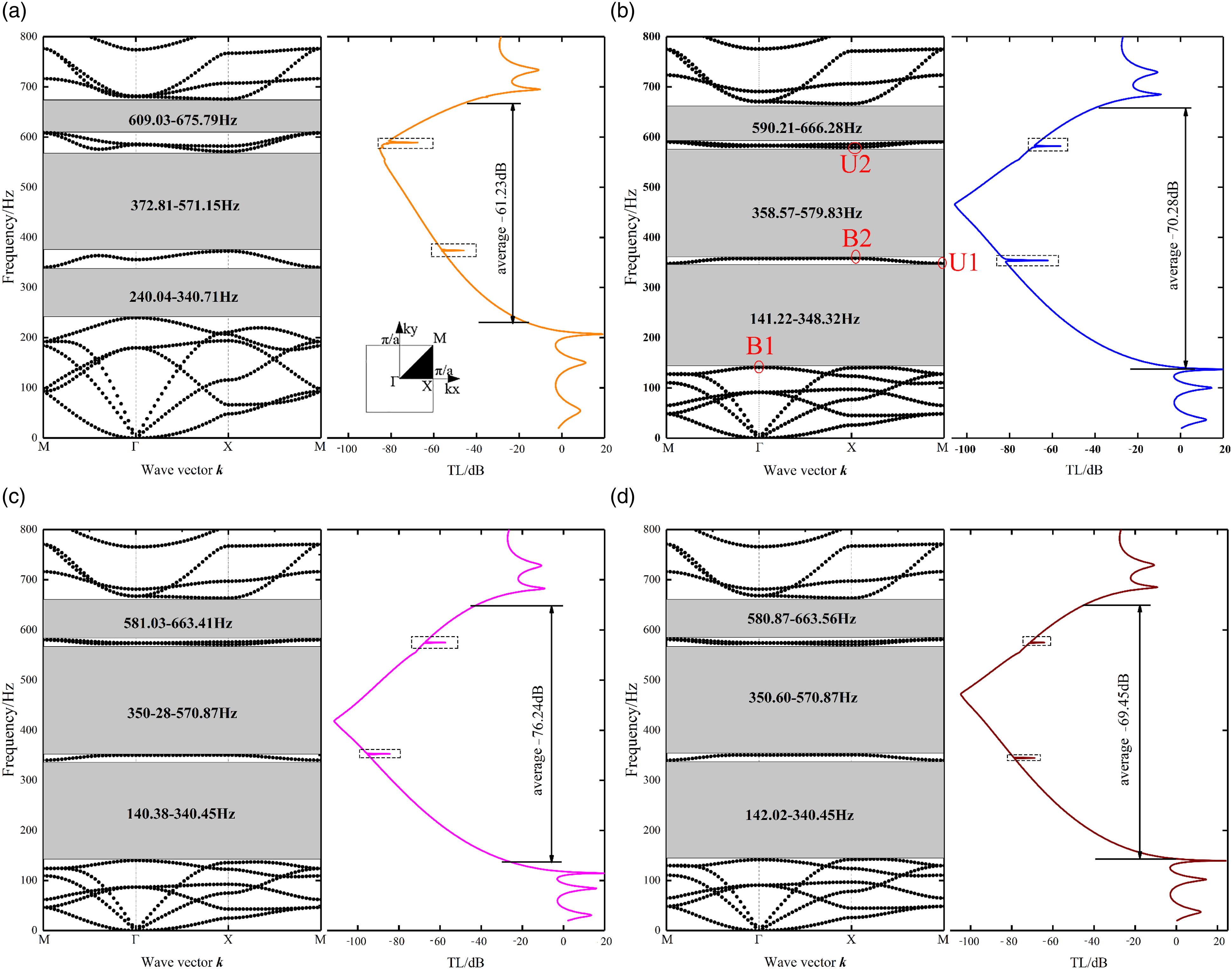
Figure 3(a) represents the energy band structure and vibration loss curves of the control group. Figures 3b, (c), and (d) show the energy band structure and vibration loss curves of PC1, PC2, and PC3, respectively. It is clear from Figure 3 that the first band gaps of PC1, PC2, and PC3 range from 141.22–348.32 Hz, 140.02–340.45 Hz, and 140.38–340.45 respectively, while the first band gaps of the control group range from 240.04 to 340.71 Hz, with higher starting frequencies and lower cutoff frequencies than the other three. This results in a smaller bandgap width than the control group than the PC1, PC2, and PC3. Furthermore, the control group has lower starting frequencies for the three bandgaps than the other three phononic crystals and smaller average vibration loss values over the three bandgap range than the other three models, so the overall damping performance of the control group is poorer. It is worth noting that the starting frequency of the first bandgap of PC1, PC2, and PC3 is almost the same, and the termination frequency of the first bandgap of PC2 and PC3 is equal. However, the termination frequency of the first bandgap of both PC2 and PC3 is 8 Hz lower than that of PC1, and thus the width of the first bandgap is narrower than that of PC1.
PC1, PC2, and PC3 all have a first band gap and a second band gap with a width of more than 200 Hz within 800 Hz, which enables them to obtain excellent damping effects in a wide-frequency range. Besides, the average vibration loss value of PC1 in three band gaps is −70.28 dB, which shows that PC1 has excellent vibration loss performance. The average vibration loss value of PC3 in three band gaps is −0.83 dB lower than that of PC1, but the average vibration loss value of PC2 in three band gaps is −5.98 dB higher than that of PC1. From a structural or material point of view, the tungsten metal embedded in the PC2 is a solid cylinder and therefore uses more material and is heavier than the PC1 and PC3.
It should be pointed out that the sweep frequencies inside the dashed boxes correspond to 2 Hz, and all remaining sweep frequencies correspond to 10 Hz. In addition, the start and end points of the first bandgap of the PC1 are in the XM region and the second bandgap is in the ΓX region. Point B represents the start point and point U represents the end point, so as to analyze the bandgap generation mechanism in the next section.
Analysis of bandgap formation mechanism
In order to reveal the physical mechanisms behind the high sound absorption, we used PC1 as a study sample and calculated the total vibration displacements of B1, U1, B2, and U2 in Figure 3(b), as shown in Figure 4. The green arrows represent the displacement vectors. The total vibration displacement of different points in Fig. 3(b). The green arrows represent the displacement vectors.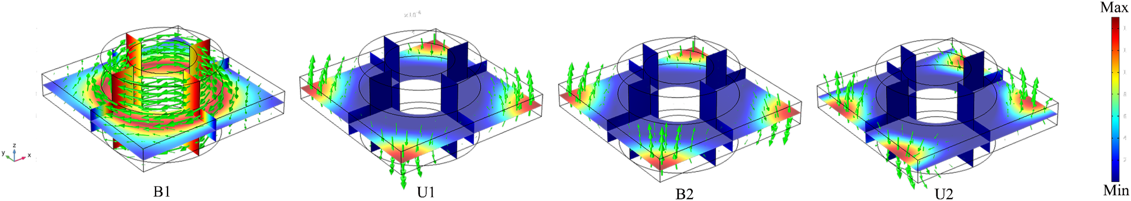
Firstly, it is necessary to understand the sweep path of the wave vector. When sweeping in the XM direction, the wave vector coAmponents kx =
Due to the high mass density of the tungsten metal block, coupling effects are more likely to occur, so this is the reason why we use tungsten material. At the point U1, the four right angles of the rubber substrate vibrate up and down along the z-axis. The opposite corners vibrate in the same direction, the same side vibrates in the opposite direction, and the displacement of the tungsten block hardly changes at all. kx and ky are both perpendicular to each other at this moment with the vibration direction of the four corners of the rubber. Therefore, in the rubber matrix, the two relative inverse motions convert the longitudinal waves of the sound waves into transverse waves, which impede the propagation of the sound waves and thus consume the sound wave energy. From Figure 4, (U)2 and B2 are also similar to U1. The vibration modes of U2 and U1 are approximately the same, and the difference between the vibration mode at the B2 point and U2 is that the vibration direction of the rubber substrate of B2 is the same on the same side and at a small distance from the right angle. The above situation is the reason for the formation of the band gap.
It is important to pay special attention to the fact that in the coupling zone of the rubber material, the motion of the rubber is complex and includes both longitudinal and transverse waves. Therefore, wave mode transformation occurs here. The increased wave mode conversion of the damped rubber makes the shear wave loss larger, so that the phononic crystal structure can absorb the shear wave component significantly.
Vibration loss analysis of phononic crystals introduced into sandwich panels
As the main material in the field of sound insulation and vibration damping, sandwich structures are required to have good acoustic and mechanical properties as well as practicality and enforceability of space operations. Similar to the structure designed in Ref,
12
it is difficult to use in practice. The vibration loss properties of the phononic crystal obtained in the previous section are necessary to be examined in the actual sandwich plate. In this section, we still choose PC1 as the research object to be embedded in the sandwich core to form a phononic crystal sandwich plate (called PCSP), as shown in Figure 5(a).At the same time, a flat sandwich plate (called control A) and a pure rubber sandwich plate (called control B) are set as control groups to study and compare the vibration loss performance of the phononic crystal designed in this paper, where the upper and lower panels are w = 2 mm thick, the distance between the two plywood panels is 3a, and the spacing between the internal crystal panels is a. (a) shows the three sandwich panel models studied in this section, which are PCSC, control A, and control B. (b), (c), and (d) show the vibration loss curves (left axis) and acceleration response curves (right axis) of PCSC, control A, and control B, respectively.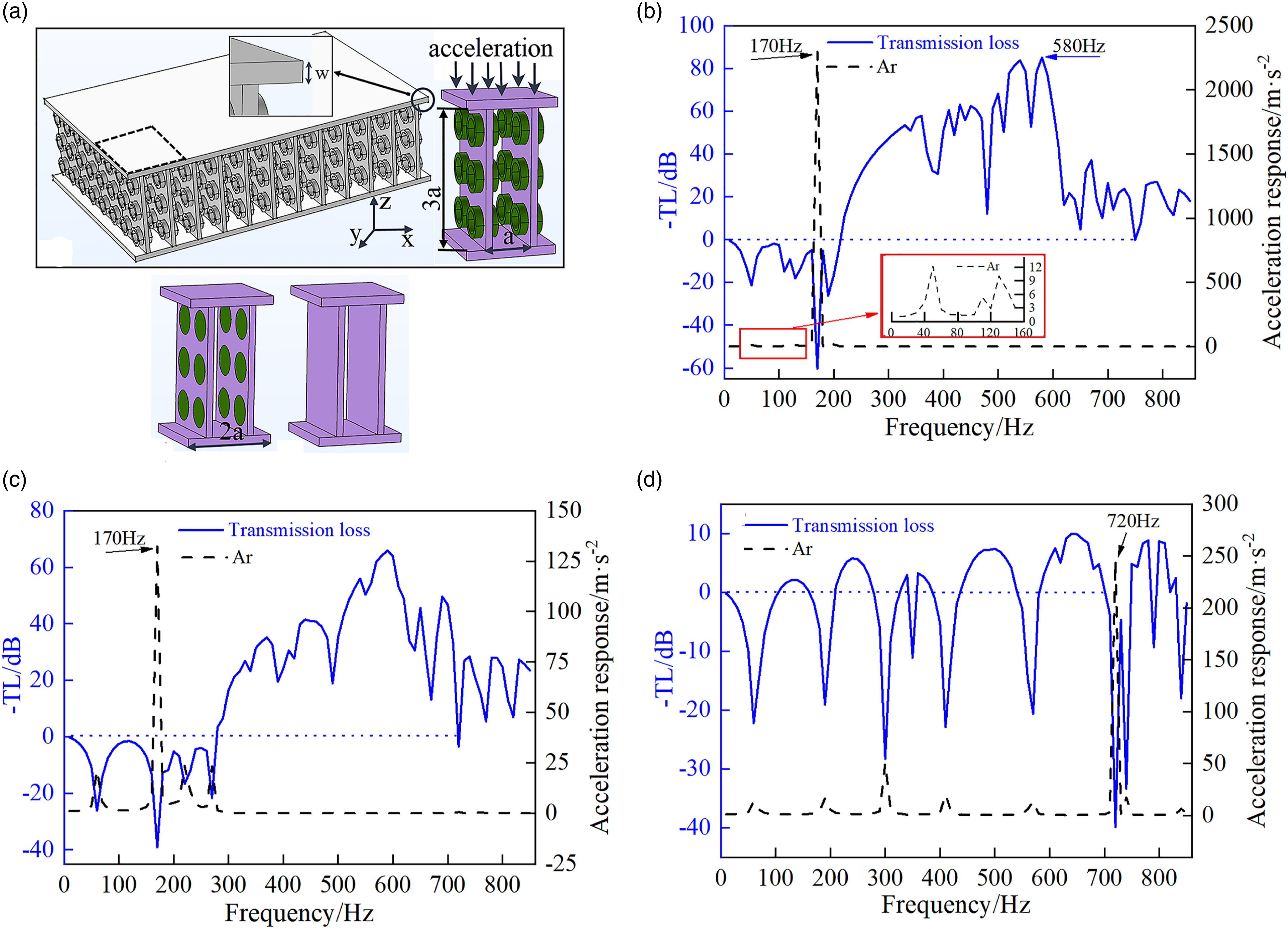
A vibration excitation is applied to the upper panel to obtain the vibration loss (left axis) and acceleration response (Ar) curve of the bottom plate (right axis) as shown in Figure 5. The PCSP still exhibits the attenuation characteristics of the forbidden band in Figure 5(b). Compared with the non-sandwich phononic crystal plate, the overall performance of the PCSP is slightly reduced with additional peaks and valleys apparent. Nonetheless, it displays a superior damping performance compared to the pure rubber splint which has almost no wide-frequency attenuation performance.
The most noticeable feature is that the acceleration amplitude of the PCSP at 170 Hz exceeds 2000 m/s2. However, the FTPCSP exceeds 125 m/s2 (Figure 5(c)), which is extremely unfavorable to low-frequency vibration reduction. The peak acceleration of the pure rubber splint is 720 Hz (Figure 5(d)). Based on this, it can be concluded that the addition of phononic crystals causes the modal resonance frequency of the system to move to the low-frequency region of 170 Hz as well as intensify the vibration amplitude at this frequency. Vibration displacement diagrams can provide some insight into the causes of vibration generation. Figure 6 shows the displacement and deformation at the low point (170 Hz) and the highest peak point (580 Hz) of the hollow crystal splint loss curve, respectively. As shown, the vibration at 170 Hz is transmitted to the lower panel to cause severe vibration, with the maximum deformation reaching 2 mm. However, at 580 Hz, the elastic wave cannot pass through the phononic crystals and only produces a small amount of deformation on one side of the excitation source such that the vibration reduction performance is superior. In order to avoid violent vibration near 170 Hz, materials with greater rigidity are required. Displacement deformation at frequencies: (a) 170 Hz; (b): 580 Hz.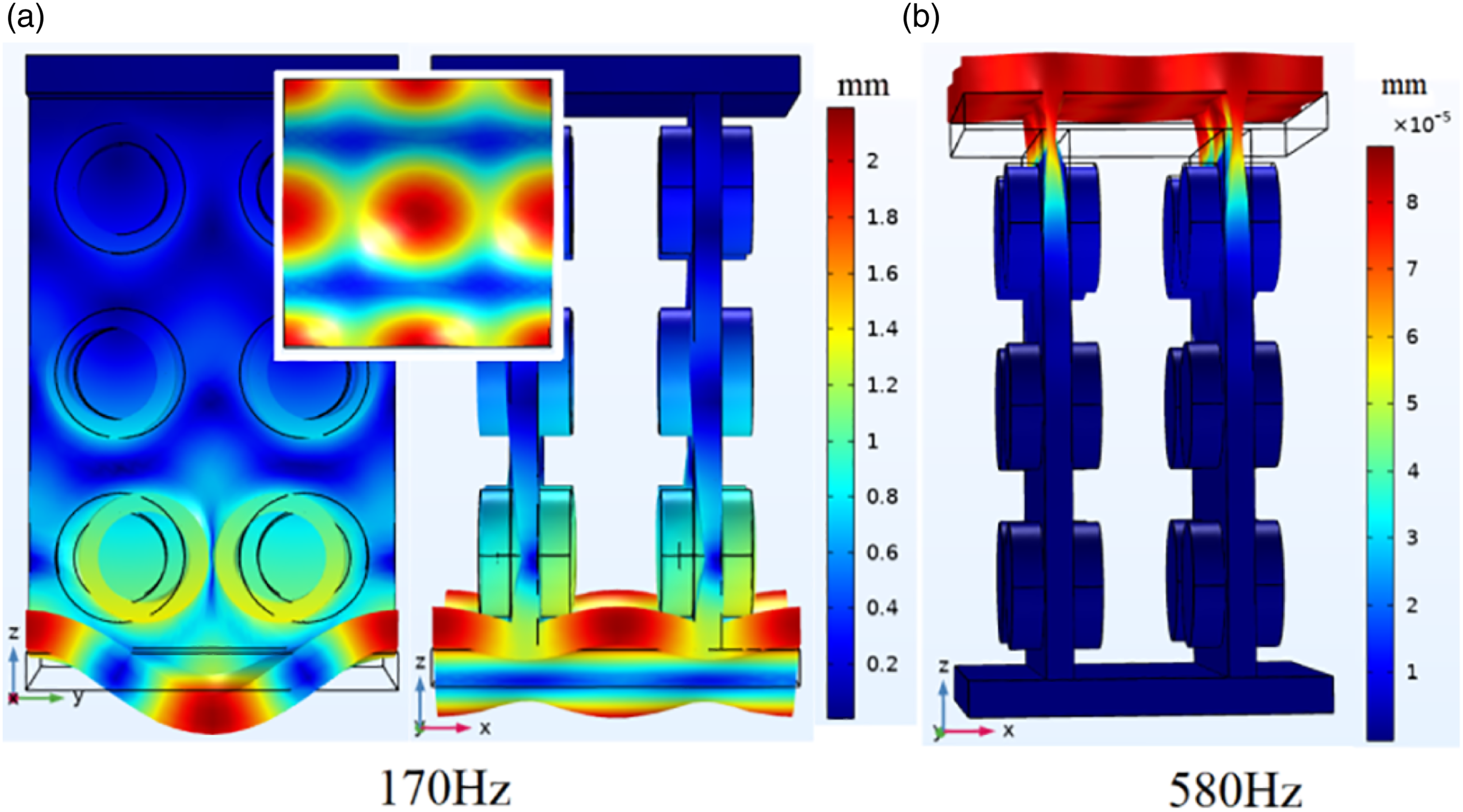
It can be seen from Figure 7 that after replacing the lower panel with a rigid structural steel plate (where ρ = 7850 kg/m3, υ = 0.3, E = 2e11 Pa), the acceleration peak at 170 Hz drops directly to 10 m/s2 whereas the two acceleration peaks at lower frequency do not change significantly. In general, the transmission loss performance in the bandgap is better than that of the rubber panel, and its performance is closely related to the bandgap characteristics of the phononic crystals. Attenuation curve of the rigid panel (lower panel is structure steel).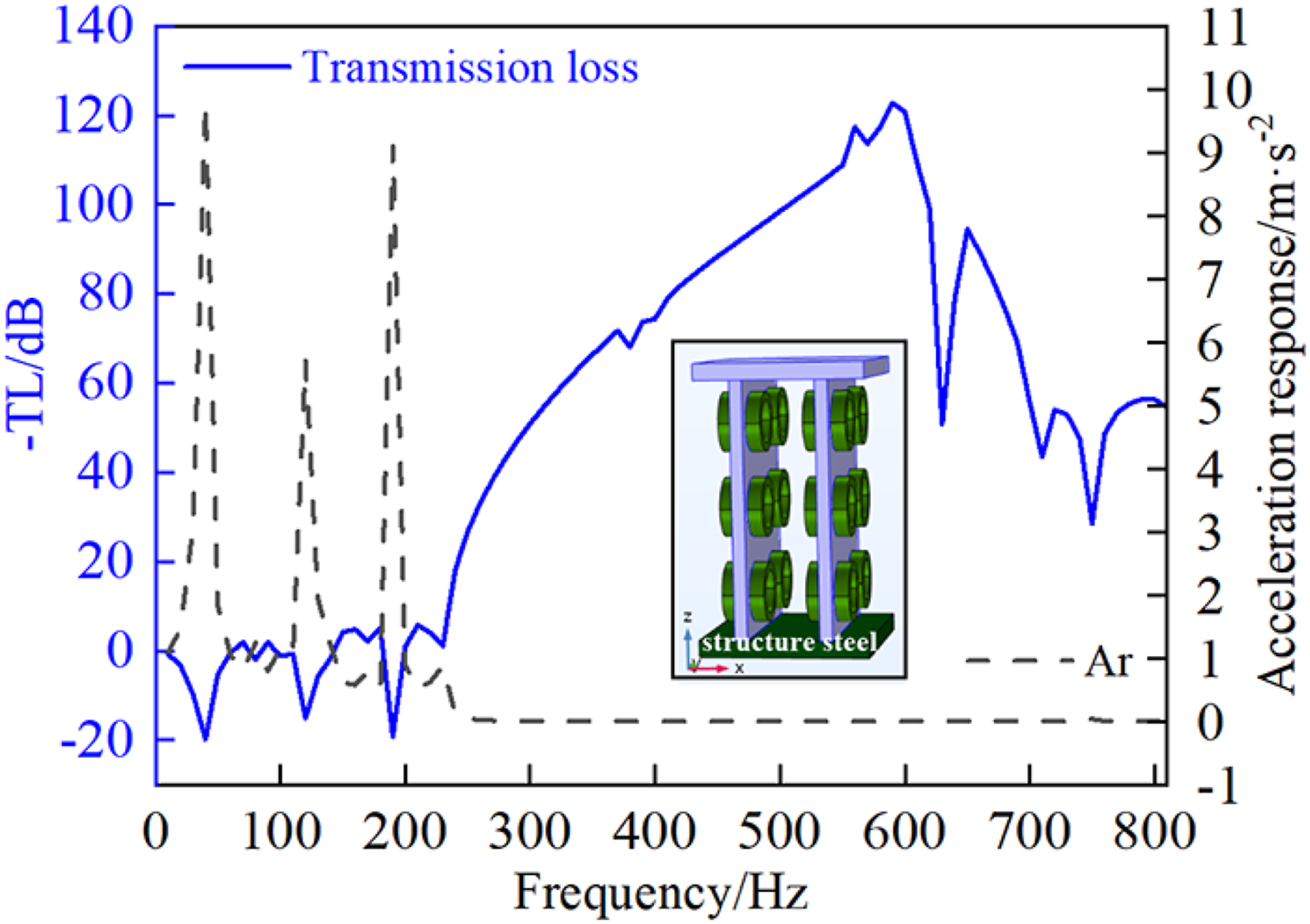
Influences of the geometric parameters on bandgap
The analysis in the above three sections demonstrates the excellent damping performance of the phononic crystal designed in this paper. Further, the size and the starting frequency of the bandgap determine the damping performance of the phononic crystal, so it is necessary to discuss the influence of the geometrical parameters on the three bandgaps of the phononic crystal proposed in this paper.
For the convenience of this section, we use SF to denote the starting frequency, TF to denote the termination frequency and W to denote the width of the bandgap. More specifically, SF-1, SF-2, and SF-3 denote the starting frequency of the first bandgap, the starting frequency of the second bandgap, and the starting frequency of the third bandgap, respectively. W-1, W-2, and W-3 denote the width of the first bandgap, the width of the second bandgap, and the width of the third bandgap, respectively. The results of the parametric analysis are shown in Figure 8. The influence of geometric parameters on the bandgap of PC1, where SF and TF are used to denote the starting frequency and the termination frequency, respectively. Triangular dashes correspond to the starting frequency and the termination frequency, short dotted lines to the width of the first band gap, line segments to the width of the second band gap, and dotted lines to the width of the third band gap.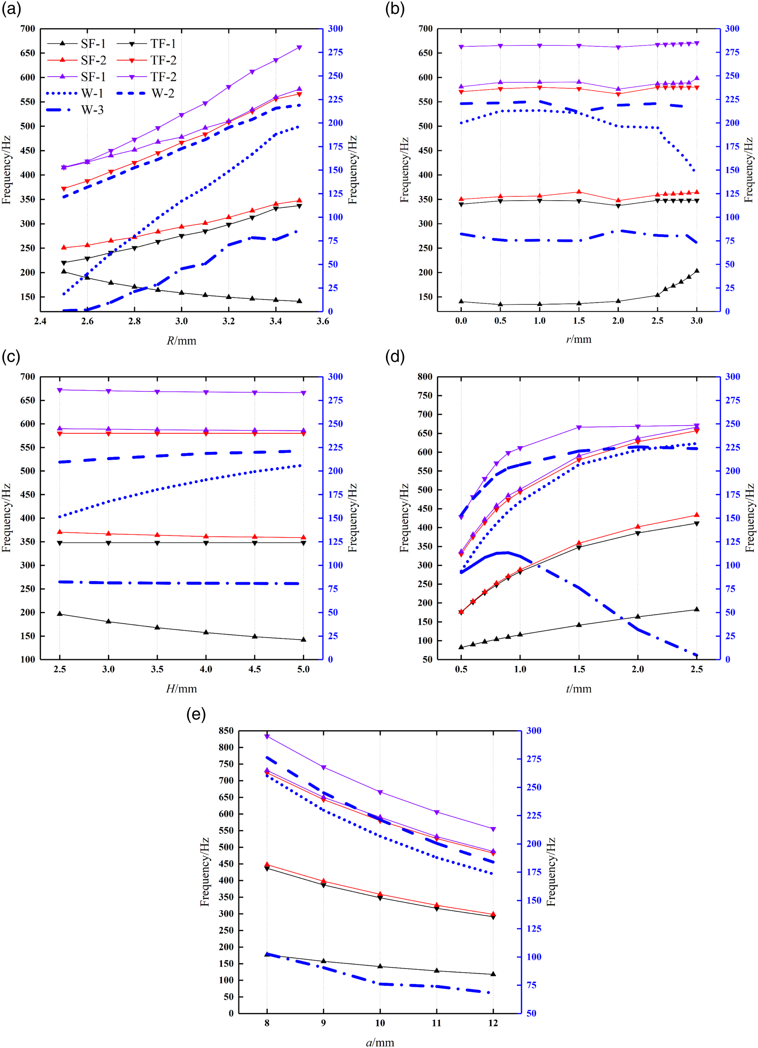
Figure 8(a) shows the effect of the outer radius R of the cup-shaped tungsten block on the three band gaps of PC1. Obviously, as R increases, the SF-1 becomes smaller but the TF-1 increases, which leads to a linear increase in W-1. Unlike SF-1, both SF2 and SF3 increase slowly as R. The decrease in SF-1 and the increase in TF-1 result in the fastest growth rate of W-1 among the three bandgap widths. It is noteworthy that at R = 2.3 mm the third bandgap disappears completely and W-1 also becomes narrow, which predicts that only one bandgap remains for PC1 below 800 Hz when R equals some value less than 2.3 mm.
Figure 8(b) shows the effect of the inner circle r of the cup-shaped tungsten block on the three bandgaps of the PCI. It is found that when r < 2.5 mm, the effect on both SF and TF for all three bandgaps is mild. It is noteworthy that SF-1 increases rapidly when r > 2.5 mm, which leads to a rapid decrease in W-1. At the same time, SF-3 gradually increases and W-3 becomes smaller. This suggests that with a constant R, increasing r thins the cup, which causes W-1 and W-3 to decrease.
Figure 8(c) shows the effect of the height H of the tungsten cup on the three bandgaps. Unlike the effect of the other geometrical parameters on the bandgap, the effect of H on the bandgap is relatively gentle. As H increases, SF-1 decreases making W-1 wider, but the changes in W-2 and W-3 are subtle. The effect of H on the low-frequency band gap is more significant.
Figure 8(d) shows the effect of the thickness t of the rubber matrix on the three band gaps. It is easy to see that a smaller t can lead to lower SF and TF. The band gap width curve shows that as t increases, W-1 and W-2 slowly increase and after t > 2.0 mm, W-1 > W-2. In addition, W-3 tends to zero after t > 0.9 mm and the third band gap will disappear completely.
From Figure 8(e), it can be understood that decreasing the lattice size a causes the SF and TF to increase, and the TF increases faster than the SF, which makes W smaller.
Conclusion
In this paper, three types of phononic crystal structures, namely, cup-shaped phononic crystal, solid cylindrical phononic crystal, and hollow circular phononic crystal, are designed by adding tungsten metal blocks to the rubber matrix. Firstly, the energy band and vibration loss analysis of the three phononic crystals were carried out by FEM, and it was found that the three phononic crystals have three complete band gaps below 800 Hz and an ultra-wide band gap with a width of over 200 Hz within 400 Hz. In addition, the average vibration loss value within the three band gaps reaches over 69 dB, which is much more outstanding than that of flat phononic crystals for low- and medium-frequency damping. Secondly, the physical mechanism of band gap formation is analyzed by using the modal of vibration displacement, which shows that the elastic waves are converted from longitudinal to transverse waves under the action of a large mass of tungsten block, thus consuming the energy of acoustic waves, and the vibration propagation is also hindered when the motion direction of the rubber substrate is at an angle of 90° to the wave vector
Footnotes
Acknowledgments
This paper is funded by the National Natural Science Foundation of China (Grant No. 52065013) and Regional Fund of National Natural Science Foundation of China (Grant No. 52165010).
Declaration of conflicting interests
The author(s) declared no potential conflicts of interest with respect to the research, authorship, and/or publication of this article.
Funding
The author(s) disclosed receipt of the following financial support for the research, authorship, and/or publication of this article: This work was supported by National Natural Science Foundation of China (52065013). National Natural Science Foundation of China (52165010).