
Abstract
Torsion deformable spatial beam and Costello theory are used to establish longitudinal-torsional-lateral coupled model of round balance rope. Based on Coulomb’s friction law and longitudinal-torsional-lateral coupled model, the nonlinear coupled dynamic model with friction constraint of round balance rope is established. Meanwhile, time-varying multi-segments non–equal-length element transformation method (TMN-ETM) is proposed to save computation time. Then, natural frequencies, lateral responses are calculated when the coupled stiffness coefficient is zero. And the calculations are compared with traditional solution method. The results show that only about few areas in the round balance rope loop have large stress norm value, while the rest parts have small stress values. Besides, dynamic responses of the balance rope with balance rope suspension rotor releasing are conducted. When the static friction is converted to dynamic friction, the friction torque and angle acceleration will be mutated at the switching instants, and slip-stick transition in angle acceleration occurs.
Keywords
Introduction
Flexible cables are light in weight and easy to fold which have been widely employed in diverse engineering applications, such as suspension bridges, 1 cable-pulley systems, 2 aerospace tether transportation system, 3 elevators,4,5 overhead crane system,6,7 cable-suspended swinging system, 8 and mine hoisting systems. 9 Hoisting ropes, conveyances, guide sheave, traction sheave, and balance ropes constitute multi-rope friction hoisting system in mine shaft. The upper ends of the balance rope are suspended at the bottom of two conveyances via balance rope suspension rotors (BRSRs). It is set up to balance the gravity of hoisting rope and obtain equal moments in mine friction hoisting system. 10 The BRSR is used to release the torsional force caused by the self-weight of round balance rope during operation. Therefore, the working state and mechanical properties of the balance rope directly affect the safe operation of friction hoisting system. 11 The round balance rope is only subjected to its own gravity during its movement, and it’s space oscillation displacement is large. Due to the inertia of round balance rope and its complex helical structure, it will cause lateral, longitudinal, and twisting or torsional vibration when round balance rope moves up and down. 12
The dynamic model of round balance rope established by traditional coordinate system is relatively complex. Thus, Shabana et al. 13 proposed absolute nodal coordinate formulation (ANCF) and applied it to the model and analyzed large deformation of cantilever beam. Lan et al. 14 proposed a new high-voltage electricity wire model to simulate the dynamic behavior of the wire after failed tensioning and during the nonlinear sliding between the wire and the iron tower. Wang et al. 15 presented the dynamic model of flexible filament bundle with viscoelasticity based on ANCF and analyzed its dynamic behavior. Zhang et al. 16 established a dynamic model of flat balance rope under multiple constraints with friction via using ANCF with non–equal-length element division method. These scholars focused on studying the translational motion of slender beam in plane, but ignored spatial torsion effect of slender beam.
Vetyukov et al. 17 proposed a rod model for large bending and torsion of an elastic strip, aiming at studying the bends and twists under the action of gravity force and varying span length between two clamped ends. Dmitrochenko et al. 18 studied the dynamical behavior of a uniform-rotating helicoseir with one fixed using ANCF. Yoo et al. 19 proposed a new finite element of a thin spatial beam using ANCF and Frenet frame, and implemented the model of a thin strip rotating around a vertical axis. However, Frenet frame is undefined at the inflection points and straight segments of the beam where its curvature is zero, leading to singularities and errors in their numerical analysis. 20
Shanana et al. 21 proposed using ANCF to model three-dimensional beam elements with the slope continuity, thereby analyzed its large rotation, torsion, shear, deformation, and the rotation of the beam cross section at the nodal points. Lots of scholars use 3D ANCF beam to analyze the dynamics of rotating shaft.22,23 However, 3D ANCF beam elements yielded too large torsional and flexural rigidities so that shear locking effectively suppressed the asymmetric bending mode for a slender flexible spatial beam. Schwab et al. 24 proposed new absolute nodal coordinate formulation with the elastic line approach to calculate a slender flexible spatial beam. Dombrowski 25 developed a large deformation beam element to describe slender beams with non-ignorable torsion effects. The number of degrees of freedom of this element is reduced from 24 to 14 compared to the three-dimensional flexible beam element proposed in reference. 26 This will effectively alleviate the problem that the computational efficiency is too slow due to too many degrees of freedom (DOFs). Yang et al. 27 proposed an improved variable-length beam element based on ANCF and arbitrary Lagrangian–Eulerian description to build dynamic model of a one-dimensional medium with mass transportation and a non-ignorable torsion effect, so as to research the dynamic behavior of drill pipe. However, this dynamic model does not take into account the coupled relationship between longitudinal stiffness and torsional stiffness.
Therefore, the torsion deformable spatial beam element and Costello wire rope theory are used to establish longitudinal-torsional-lateral coupled vibration of round balance rope with BRSR in friction hoisting system. Time-varying multi-segments non–equal-length element transformation method (TMN-ETM) is used to reduce the dimension of the dynamic equation matrix and save dynamics simulation time of longitudinal-torsional-lateral coupled balance rope vibration. Hence, large deformation of longitudinal-torsional-lateral coupled effect of round balance rope will be studied.
Dynamic equation of round balance rope
Physical description
Mine friction hoisting system is mainly composed of traction sheave, conveyance, hoisting rope, BRSR, and balance rope. The simplified model of friction hoisting system is shown in Figure 1(a). The BRSR is used to release the torsional force caused by the self-weight of round balance rope during operation. The outermost strand twist of multi-layer strand wire rope is formulated as outer strand twist, and the inner strand twist is formulated as inner strand twist. Due to the opposite twist direction between the inner rope and the outer rope, the torsional moment generated by the inner rope and the outer rope of the multi-layer strand wire rope can offset each other, but there is still some torsional moment in the round wire rope as shown in Figure 1(b). (a) Simplified model of friction hoisting system. (b) Schematic of the round balance rope.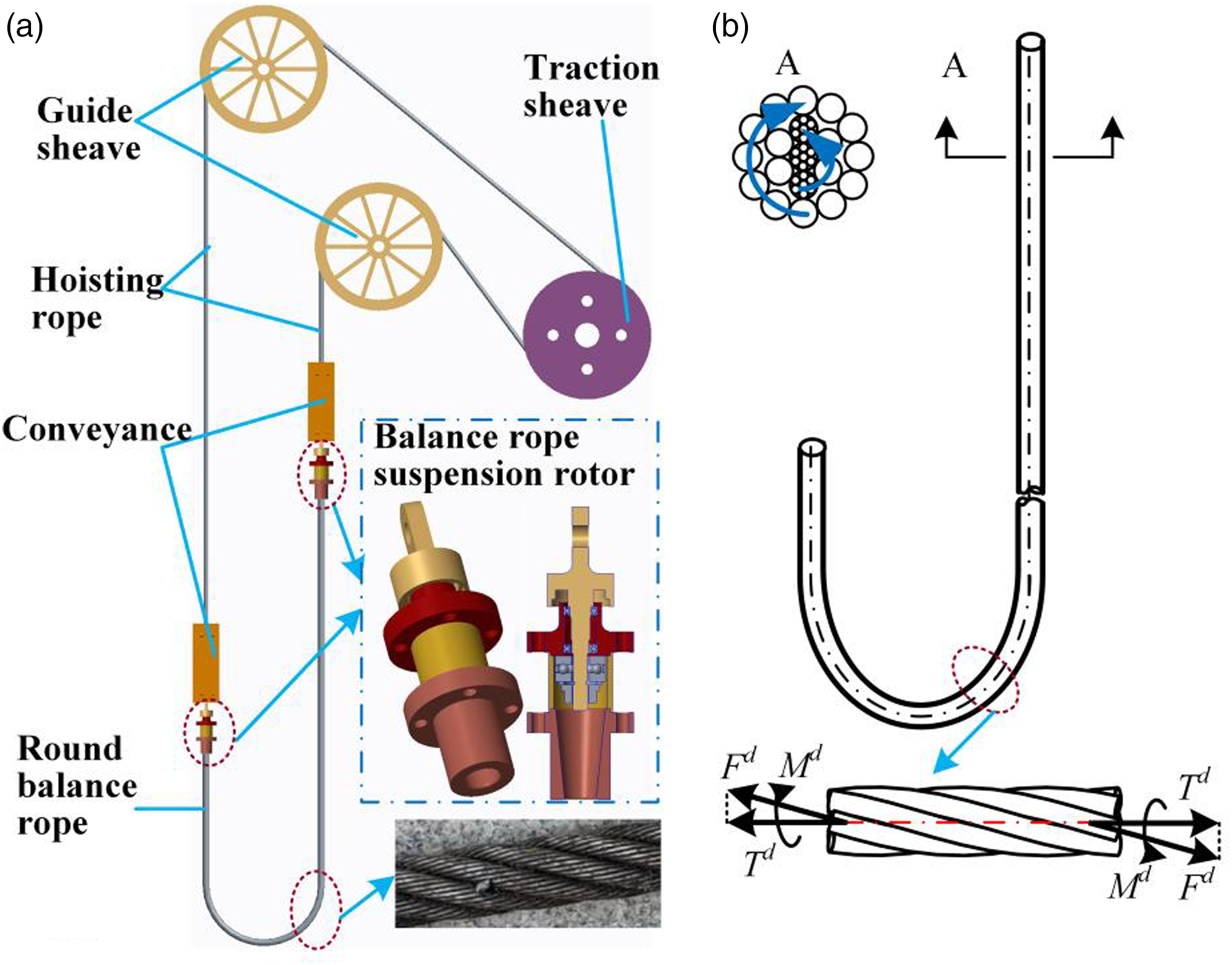
Costello wire rope theory, shown in Figure 1(b), is used to describe the coupling relationship between longitudinal and torsional stiffness of round balance rope. When the tensile-torsional deformation of the wire rope is considered and its bending deformation is ignored, the constitutive relation of the wire rope can be expressed as

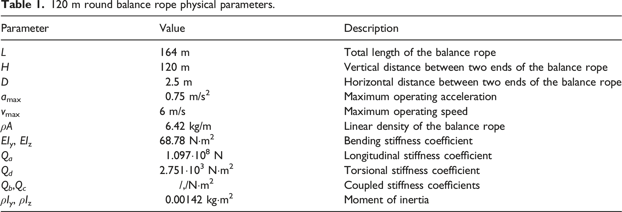
ε and τ represent axial strain and torsional curvature. T d and M d represent dynamic tension and dynamic torque in the wire rope, respectively. 12 Q a and Q d are longitudinal and torsional stiffness coefficients of the round balance rope, and Q b and Q c are coupled stiffness coefficients of the round balance rope. 28 The wire rope coupling coefficient can be obtained by importing the 3D model of the wire rope into the finite element software and then applying different boundary conditions.
However, the above constitutive relation ignores the bending deformation of the wire rope, and cannot describe the large spatial deformation behavior of the round balance rope. Therefore, it is necessary to establish a global coordinate system to describe the spatial coordinate relationship and large spatial deformation behavior of the round balance rope.
Description of coordinate systems for spatial round wire rope
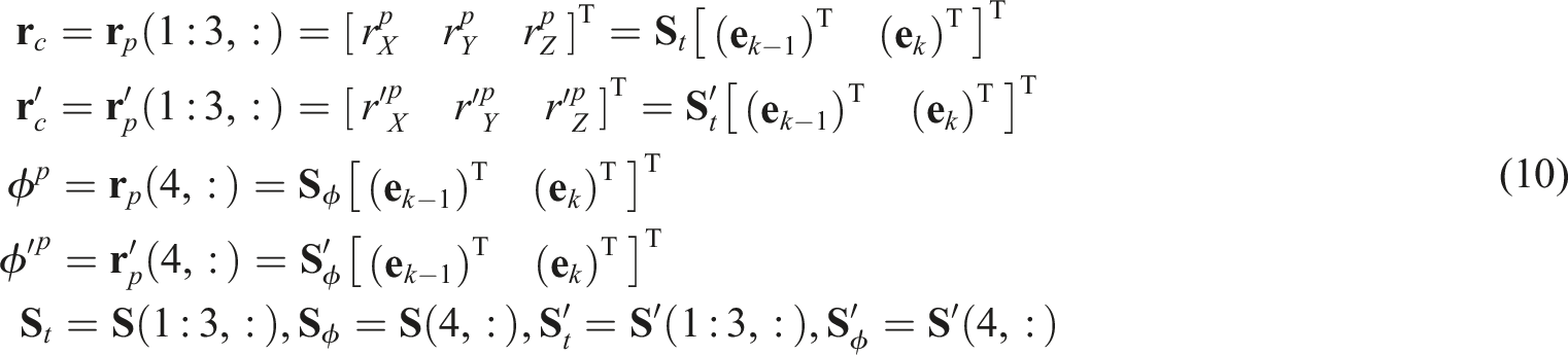
In the slack low tension rope, spatial positional posture of the round balance rope can be described from two aspects: (i) the translation of the local coordinate system of the round balance rope and (ii) the rotation of the local coordinate system on the round balance rope. The former can be represented by the position vector of the origin of the local coordinate system, namely, the position vector of the point on the center line of the round balance rope. The latter uses the direction cosine matrix Θ to realize the mapping from the local coordinate system to the global inertial coordinate system.
As shown in Figure 2(a), O-XYZ is the global inertial coordinate system, and the global position vector of the beam centerline is (a) Round wire rope in the inertial coordinate system. (b) Schematic of κ
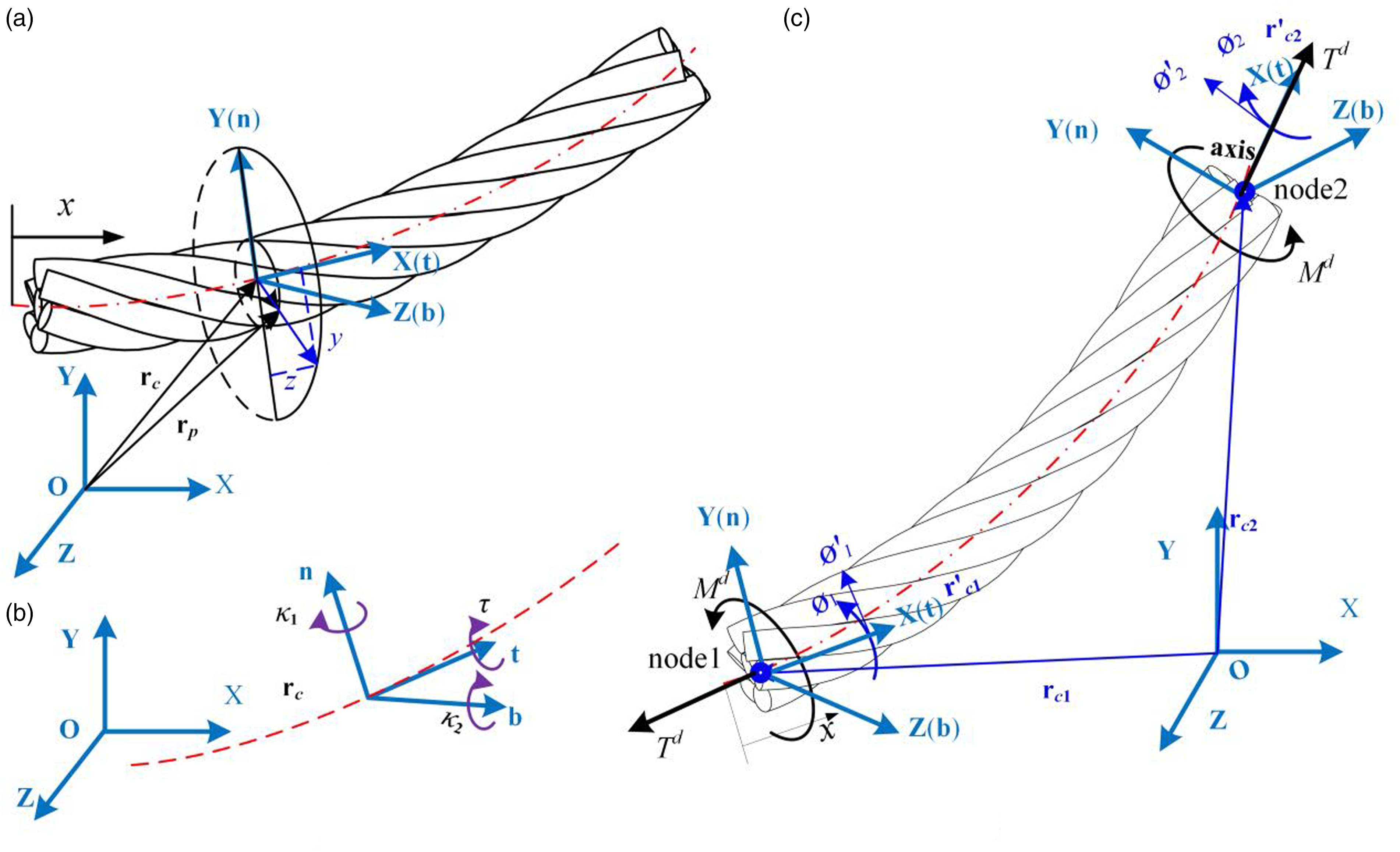
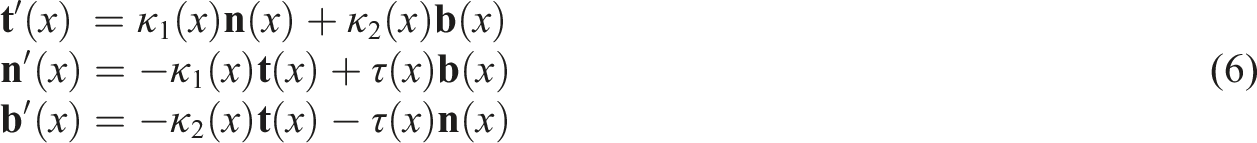
Let us define the local coordinate system on the round balance rope section as
The directional cosine matrix from the local coordinate system to the global coordinate system is

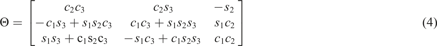
Assuming that the inertial coordinate system is rotated by Z-Y-X parallel to the local coordinate system and the corresponding Euler angle is Tait–Bryan angle,
25
the rotation matrix Θ can be expressed as

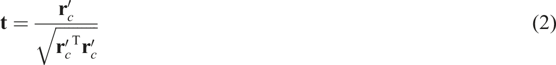
Considering the orthogonality of tangent axis


The matrix
The round balance rope is divided into seven segments in the axis direction as shown in Figure 3, and they are named part I, part II, part III, part IV, part V, part VI, and part VII, respectively. It is divided into ( Multi-segments non–equal-length element division method.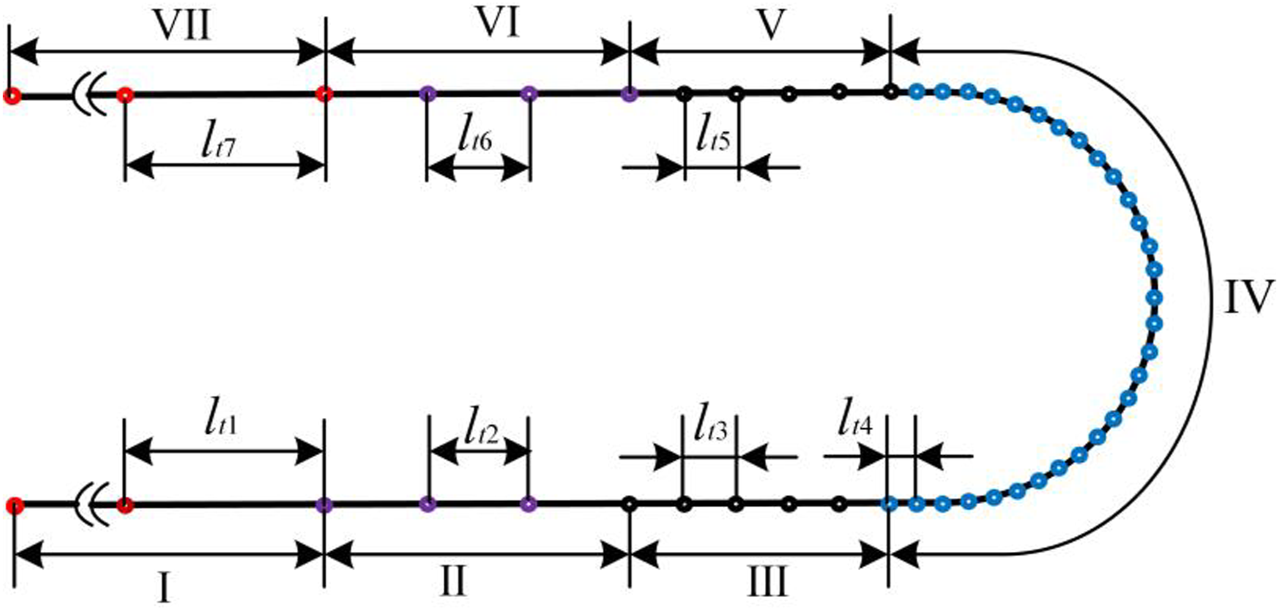
Equation derivation
Dynamic model of round balance without BRSR
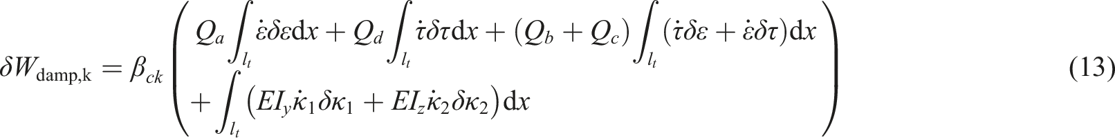
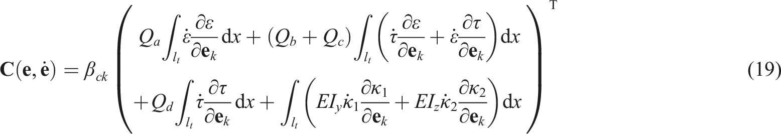
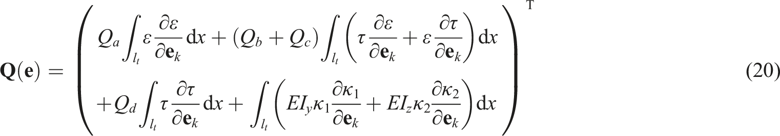
The element kinetic energy, strain energy, dissipated energy, virtual work done by the external load, gravity, concentrated force, and concentrated torque of round balance rope can be expressed as


Based on element energy expressions represented by equations (11)–(14), the dynamic equation of round balance rope can be yielded from Lagrange equation


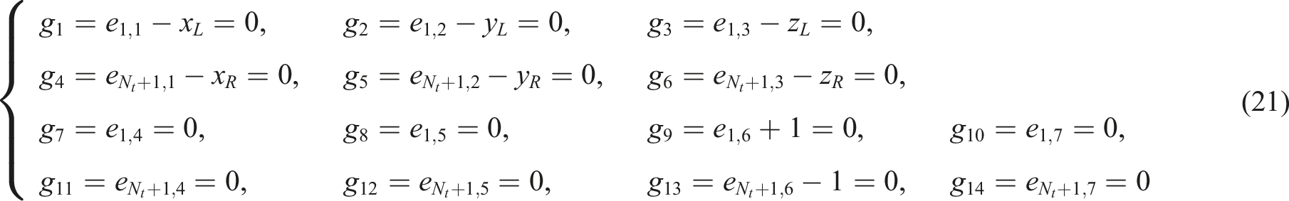
The round balance rope is fixedly connected to conveyance without BRSR

Dynamic model of round balance with BRSR
If the round balance rope is connected to the conveyance through BRSR, the constraint equation


Coulomb’s dry friction law
29
can be used to describe the contact friction force at the BRSR
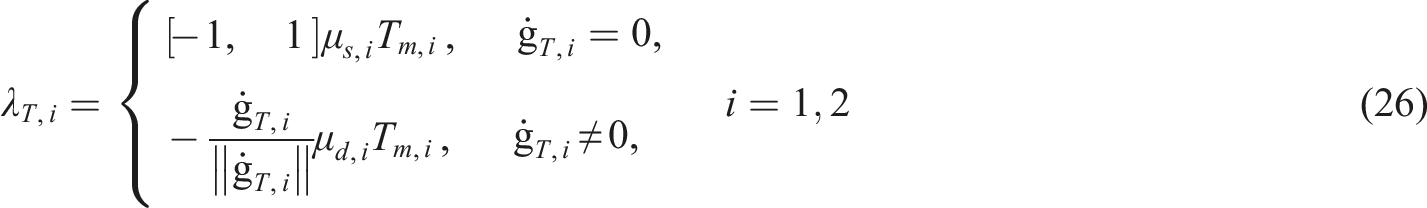


Combining equations (17) and (27) yields the dynamic equations with friction, which are expressed as
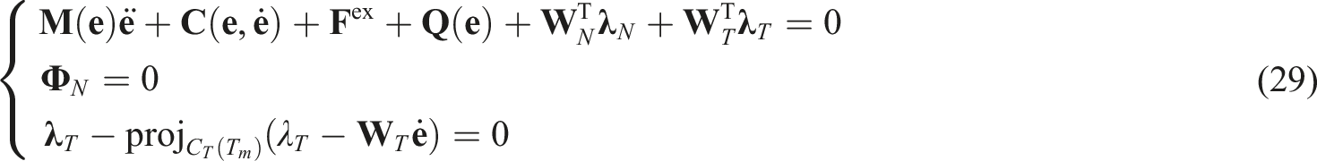
Equations (17) and (29) can be solved by the extended generalized-α algorithm. 16
Element transformation
As shown in Figure 4, the node position of the balance rope is transformed from Figure 4(a)to Figure 4(b). After the fourth segment is transformed, the number of the element in the fourth segment is evenly distributed on the left and right sides. The number of elements in the first segment is increased by one, the number of elements in the seventh segment is decreased by one, and the number of elements in other segments remains unchanged. TMN-ETM node transformation of the round balance rope.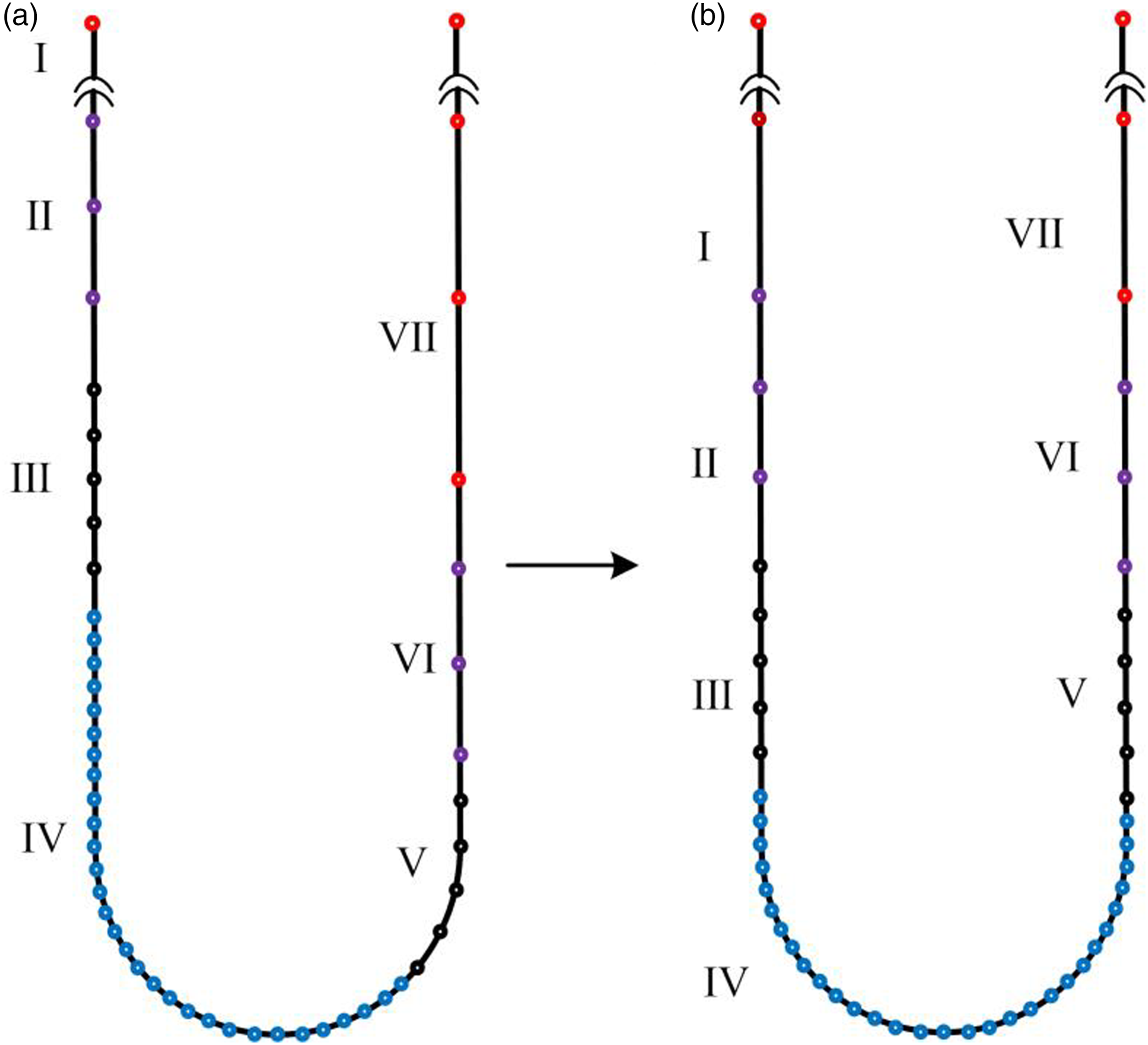
When three nodes need to be merged into two nodes at the critical point of the second segment and the first segment, it can be achieved by equation (30)


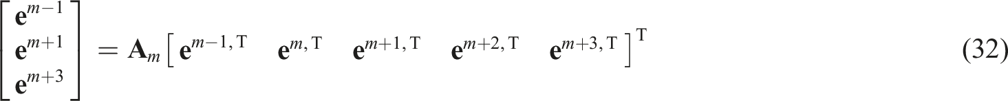
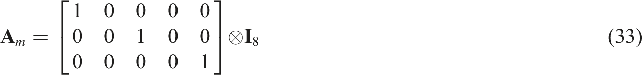


Among them,
At the same time, velocity coordinate
Flow chart of the TMN-ETM round balance rope is shown in Figure 5, the normal time step h is divided into a slightly smaller time step Flow chart of the TMN-ETM round balance rope.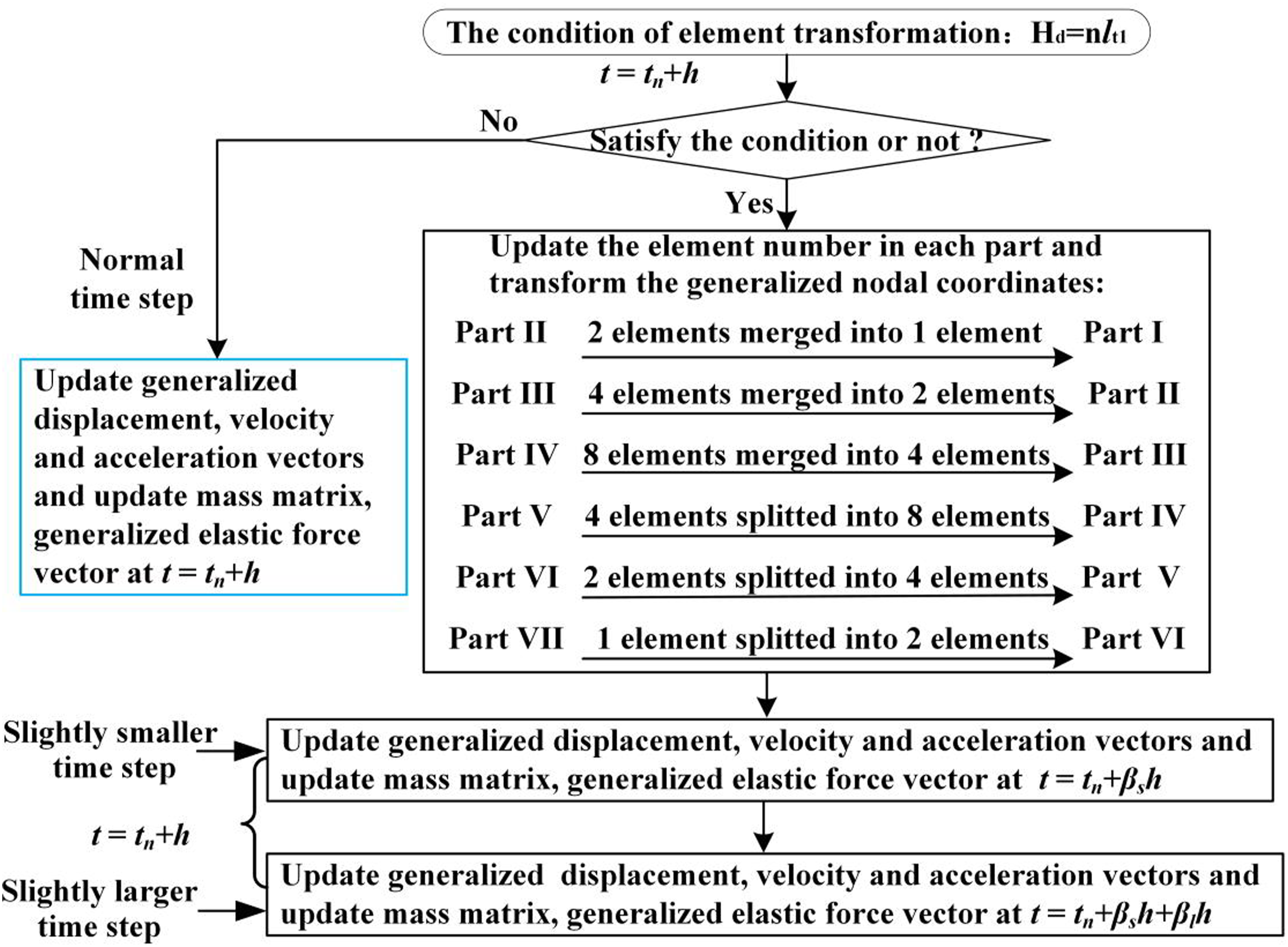
Application in round balance rope
Validation of the TMN-ETM
120 m round balance rope physical parameters.
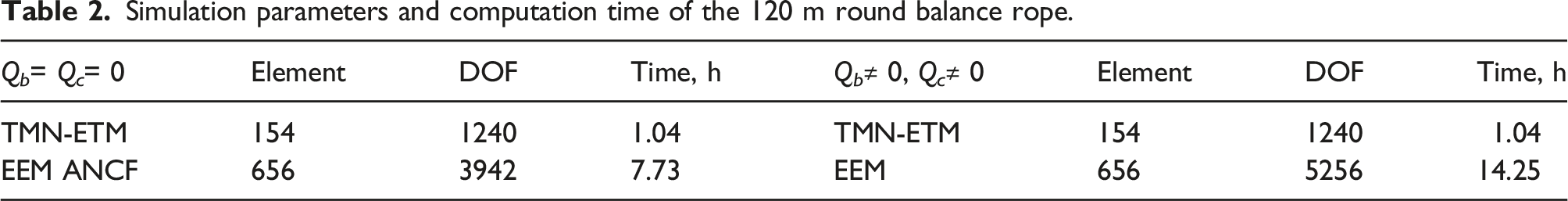
Simulation parameters and computation time of the 120 m round balance rope.
In order to verify the correctness of nonlinear coupled dynamic model with TMN-ETM, the coupled stiffness coefficients of the round balance rope in the calculation process are reduced to 0, namely, Q b = Q c = 0 N·m. Under the same physical parameters, the natural frequencies, the vibration displacement response are compared with ANSYS. The left side and right side observation positions are 3 m above the lowest point of balance rope in initial condition, respectively.
The first four out-plane and in-plane natural frequencies of the round balance rope obtained from ANSYS and TMN-ETM are depicted in Figures 6(a) and (b), separately. H is the height difference between the left and right conveyance. The solid line and dashed line represent the frequencies obtained from ANSYS and TMN-ETM, respectively. From Figure 6, it can be seen that the solid line and dashed line are completely coincident. That is to say, the frequencies obtained by the TMN-ETM and ANSYS are in excellent agreement. It is found that a curve veering phenomenon occurs in out-plane natural frequencies from Figure 6(a). However, neither frequency veering nor mode shift exists in in-plane natural frequencies of the round balance rope. In-plane natural frequencies do not change too much with the position of conveyances. First four out-plane and in-plane natural frequencies of the 120 m round balance rope.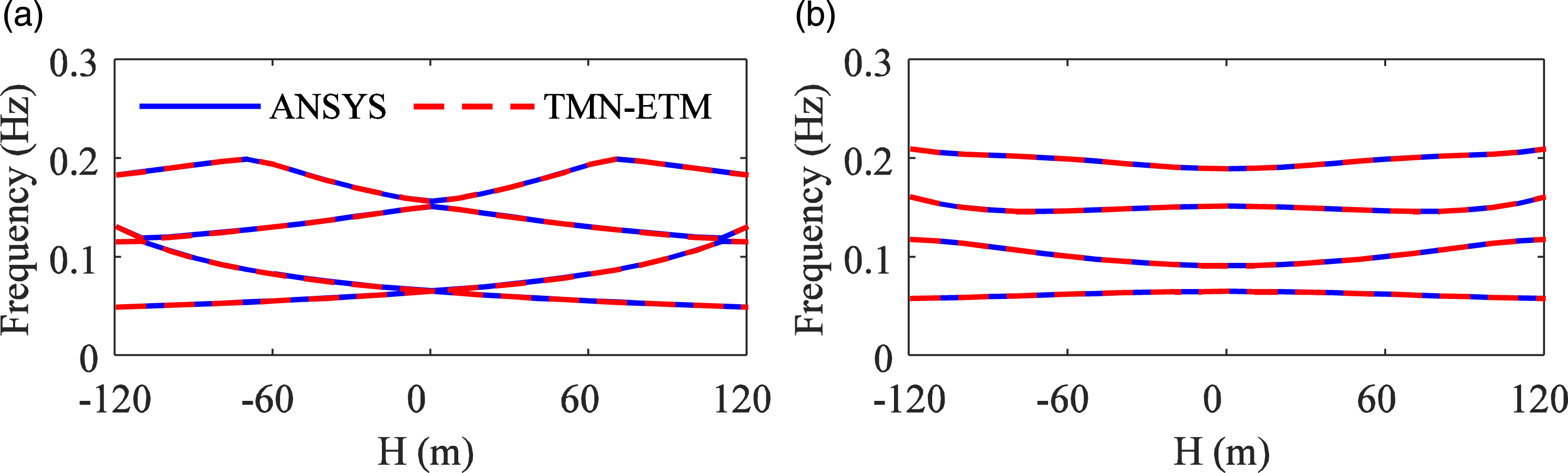
For the round balance rope under the non-excitation condition, the dynamic analysis is carried out by MATLAB. The lateral displacements of the selected space positions on the round balance rope are shown in Figure 7. The solid line and dashed line represent the displacements obtained from ANCF with equal-length element method (EEM), and nonlinear coupled dynamic model with TMN-ETM, respectively. From Figure 7, it can be seen that the lateral displacements of the selected space positions are in good agreement by two methods. That is to say, the lateral displacements of the round balance rope obtained by the TMN-ETM meet the error requirements when the coupling stiffness coefficient is zero. Lateral displacements of the selected positions.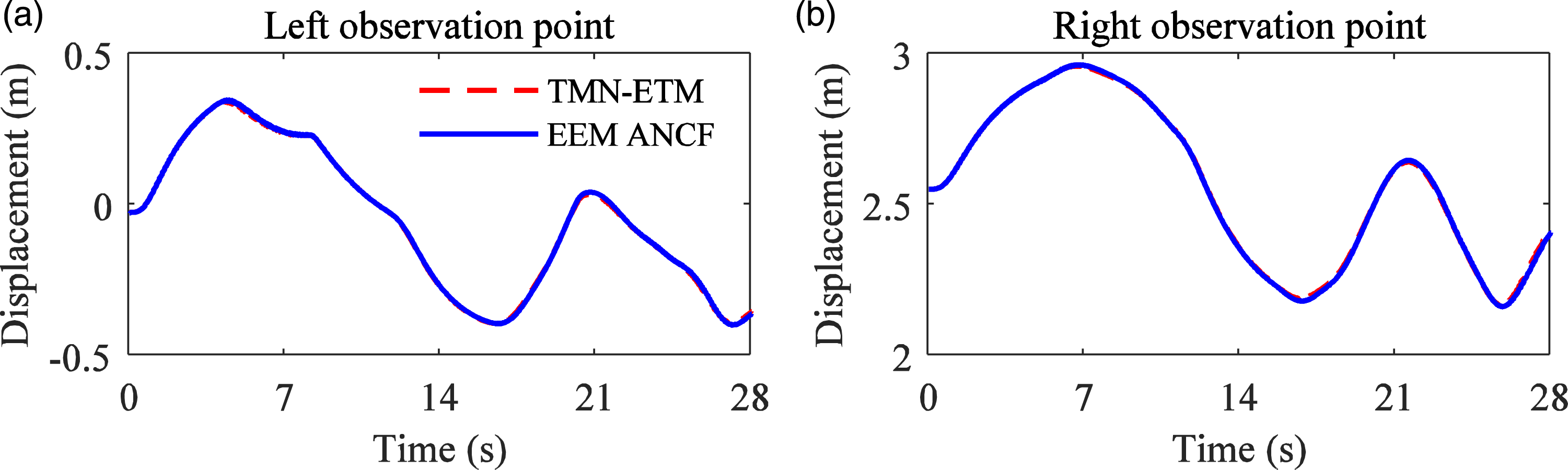
When the coupled stiffness coefficients of the round balance rope are not zero, set Q
b
= 2.371 × 10⁵ N·m, Q
c
= 2.301 × 10⁵ N·m, the correctness of nonlinear coupled dynamic model with TMN-ETM is verified by comparing dynamic response obtained by the nonlinear coupled dynamic model with EEM and nonlinear coupled dynamic model with TMN-ETM. For the round balance rope under the non-excitation condition, the dynamic analysis is carried out by MATLAB. The out-plane displacements and in-plane displacements of the selected space positions on round balance rope are shown in Figure 8. The solid line and dashed line represent the displacements obtained from the EEM and TMN-ETM, respectively. The arrow direction indicates the movement direction of round balance rope. As shown in Figure 8, out-plane lateral displacement at left observation point is negative, while out-plane lateral displacement at right observation point is positive. The left side out-plane lateral displacement and the right side out-plane lateral displacements do not jump between positive and negative values. The torsional displacements of the selected space positions on round balance rope are displayed in Figure 9. The solid line and dashed line represent the displacements obtained from the EEM and TMN-ETM, respectively. Since the coupled stiffness coefficients of the round balance rope is not zero, the longitudinal vibration of the round balance rope will cause torsional vibration of the round balance rope shown in Figure 9, which will drive the torsion of the round balance rope, and then generate out-plane lateral vibration. Lateral displacements of the selected positions of the 120 m round balance rope. Torsional displacements of the selected positions of the 120 m round balance rope.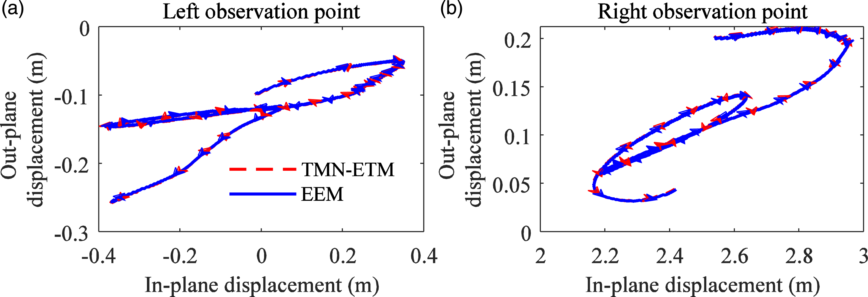
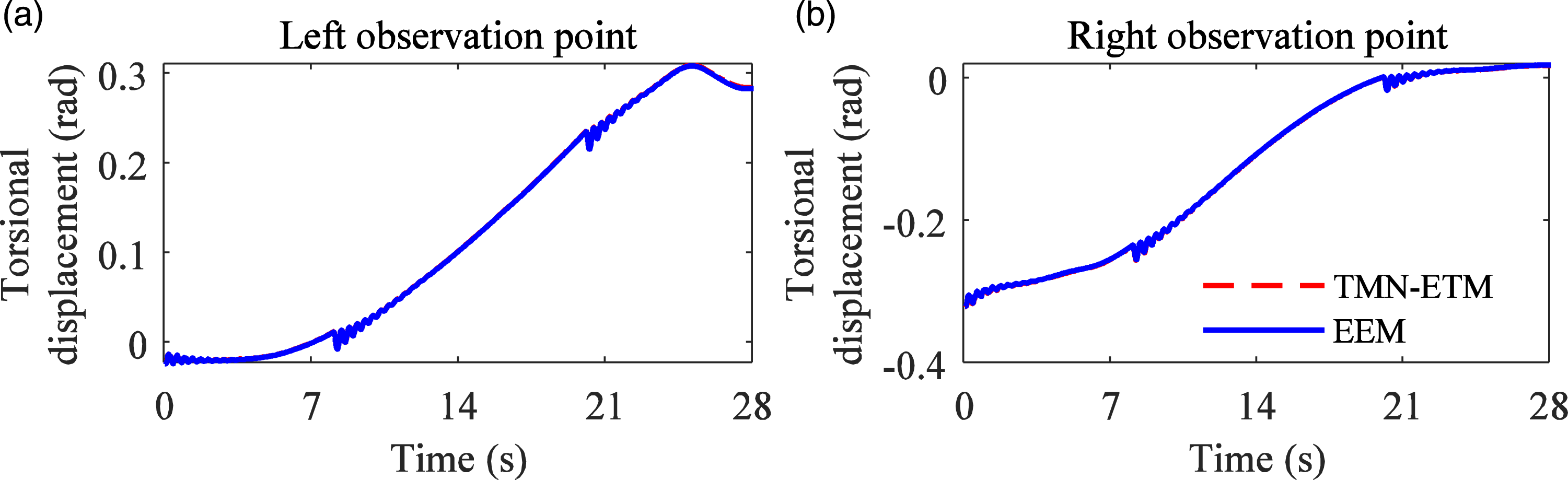
It can be noticed from Figures 8and 9that out-plane, in-plane, and torsional displacements of the selected space positions are in good agreement by two methods. That is, the lateral displacements and torsional displacements of the round balance rope obtained by the TMN-ETM meet the error requirements when the coupling stiffness coefficient is not zero.
Figures 10 and 11 show the element stress norm diagram of the round balance rope removing first and last element nodes. Figures 10(a)and 11(a)demonstrate the element bending stress and element torsional stress norm diagram by EEM, respectively. The highlighted part in the element bending stress norm diagram described in Figure 10(a)represents the element stress norm value of the round balance rope bending part, and the curve formed by the highlighted part corresponds to the displacement curve of conveyance. It can be seen from Figure 10(a)that only about few areas in the round balance rope loop have large stress norm value and are in bending state, while the rest parts have a small stress value and are in approximately straight state. Similarly, the same pattern appears in the element torsional stress diagram from Figure 11(a). Therefore, it is only necessary to perform finer element division in the places where the bending stress value and the torsional stress value are large, while the elements in other areas can be slightly rougher, thereby reducing the number of elements. Figures 10(b)and 11(b)illustrate the element bending stress and element torsional stress norm diagram by TMN-ETM. It can be seen from Figures 10and 11that the maximum values of element bending stress and the element torsional stress norm value obtained by the two methods in the calculation process are the same, and the amplitudes are relatively close. The element bending stress and element torsional stress norm value are stable over the time domain, and there is no sudden change in stress due to node transformation. This shows that the proposed method does not produce spurious stress caused by the longer element length of vertical segment. It can be proved that the proposed method is stable and convergent over the entire motion time domain. Element bending stress norm value of the 120 m round balance rope. Element torsional stress norm value of the 120 m round balance rope.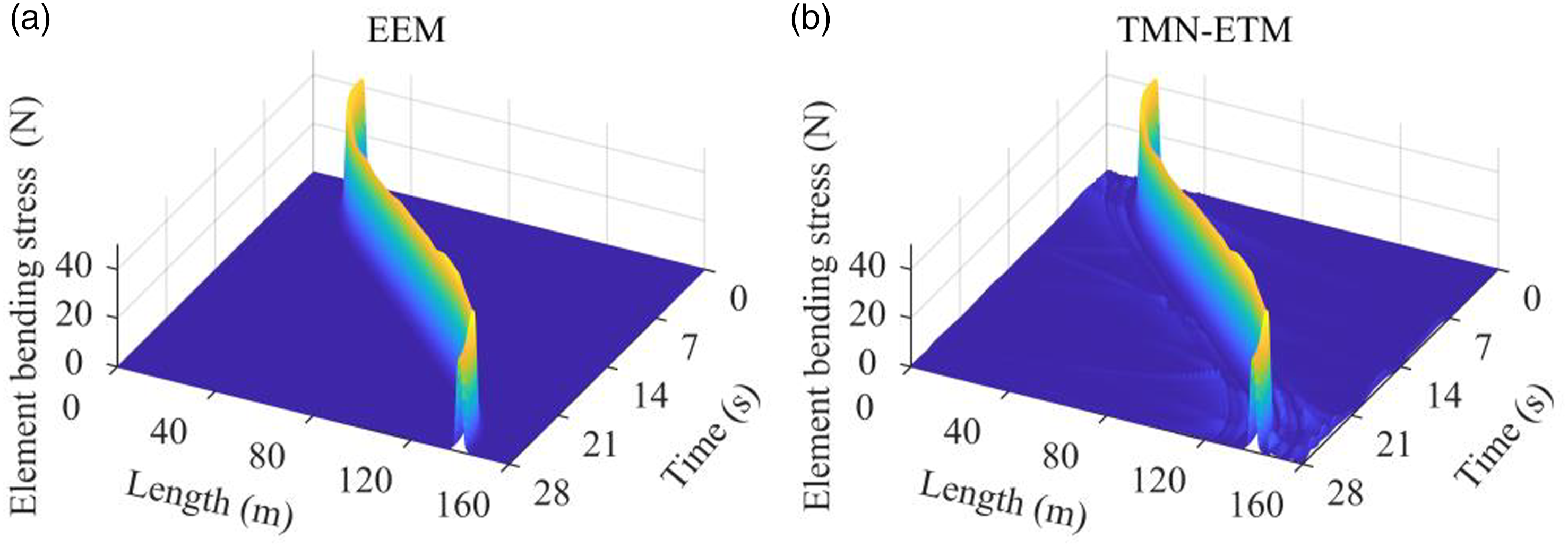
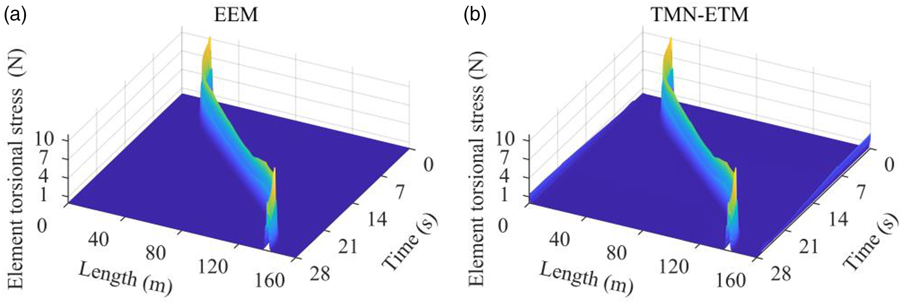
Figure 12(a) shows kinetic energy of the round balance rope. The blue solid line represents the kinetic energy obtained by EEM. The red dashed line and magenta dash-dotted line represent the kinetic energy obtained before and after the TMN-ETM node transformation, respectively. It can be seen that kinetic energy of the balance rope is in good agreement by EEM and TMN-ETM. The kinetic energy error between EEM and TMN-ETM is shown in Figure 12(b). It can be seen from the diagram that the relative kinetic energy error generated through the TMN-ETM is less than 1 J, which is much lower than the kinetic energy generated by the balance rope during the movement (difference of four orders of magnitude). The relative error of kinetic energy before and after TMN-ETM node transformation is shown in Figure 12(c). It can be seen from the figure that the relative error of kinetic energy generated by velocity change after TMN-ETM node transformation is less than 10−4 J, so the kinetic energy error generated by TMN-ETM node transformation can be ignored. (a) Balance rope kinetic energy. (b) Kinetic energy error between EEM and TMN-ETM. (c) Kinetic energy error before and after TMN-ETM node transformation.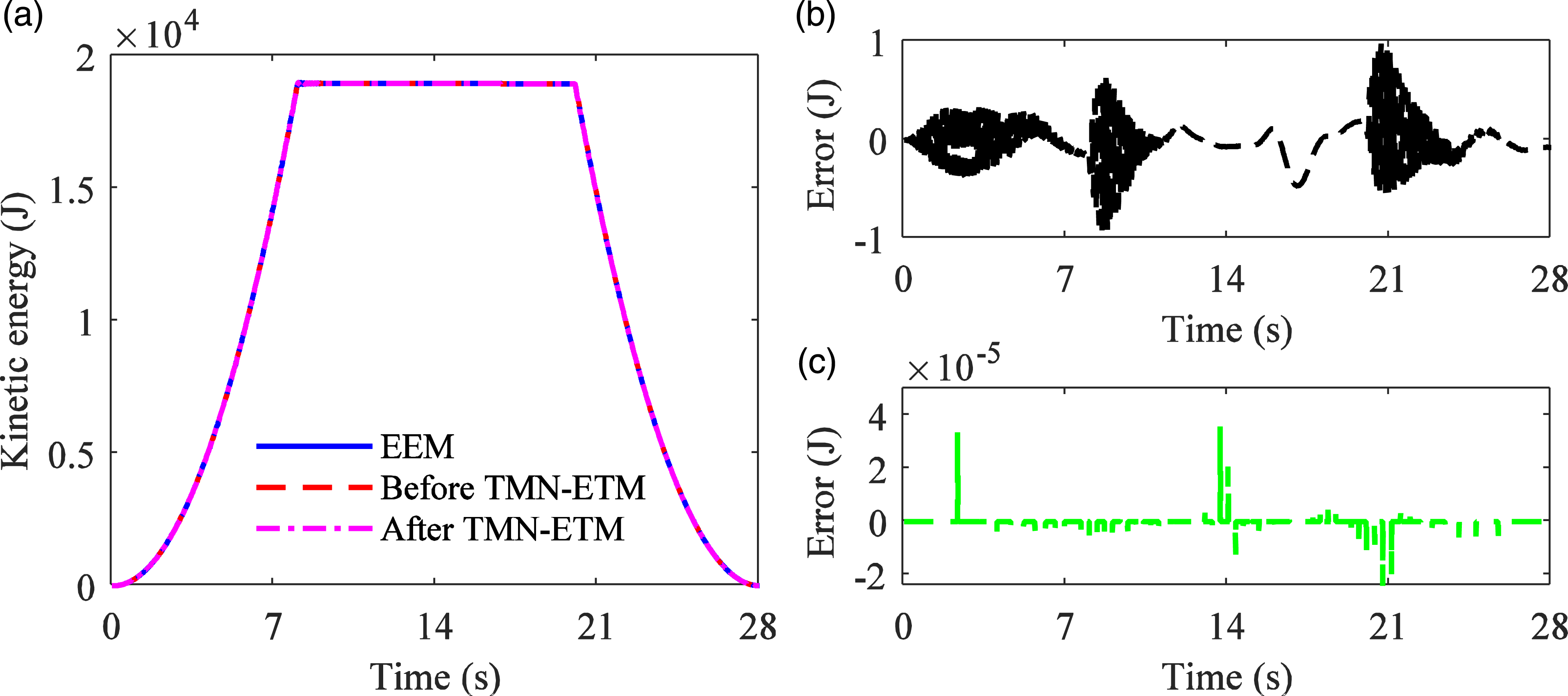
Computation time of the 120 m round balance rope is shown in Table 2. Compared with the ANCF with EEM, the element number of nonlinear coupled dynamic model with TMN-ETM is decreased by 502, and the computation time of simulation when Q b = Q c = 0 N·m under non-excitation is decreased by 86.5%. Compared with the nonlinear coupled dynamic model with EEM, the element number of TMN-ETM is decreased by 502, and the computation time of simulation when Q b ≠ 0, Q c ≠ 0 N·m under non-excitation is decreased by 92.7%. That is to say, nonlinear coupled dynamic model with TMN-ETM is stable and efficient.
By means of the same physical parameters, the natural frequencies and vibration displacements under non-excitation condition are compared with ANSYS and ANCF with EEM. We can detect that TMN-ETM is reliable and trustworthy, and TMN-ETM can be used to establish the dynamic model and analyze dynamic behaviors of the round balance rope.
Dynamic responses of balance rope with BRSR releasing
240 m round balance rope physical parameters.
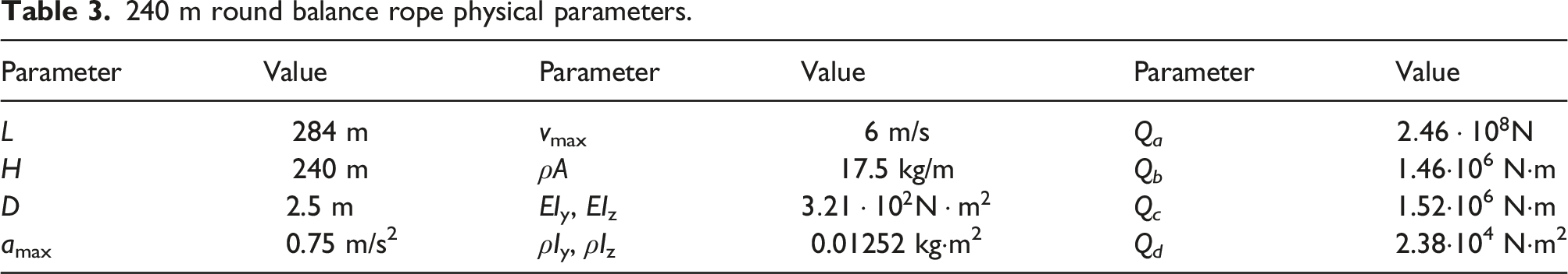
For the round balance rope under torsional friction constraint, that is equations (43), 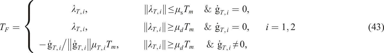
Figures 13(a)–(d) show the three-dimensional configurations of the round balance rope, its projection on XY plane and ZY plane, and torsional displacement of the round balance rope with BRSR releasing at different times, respectively. It can be seen from Figure 13that in the process of balance rope releasing torsional force, in-plane lateral displacements of the balance rope change little (Figure 13(b)), and out-plane lateral displacements and torsional displacements change violently (Figures 13(a), (c) and (d)), resulting in large out-plane lateral and torsional displacements. The out-plane lateral balance rope loop swings back and forth from negative region to positive region. (a) Three-dimensional configuration of the round balance rope at different times, and (b) its projection on the XY plane, and (c) its projection on the ZY plane, and (d) torsional displacement of the round balance rope.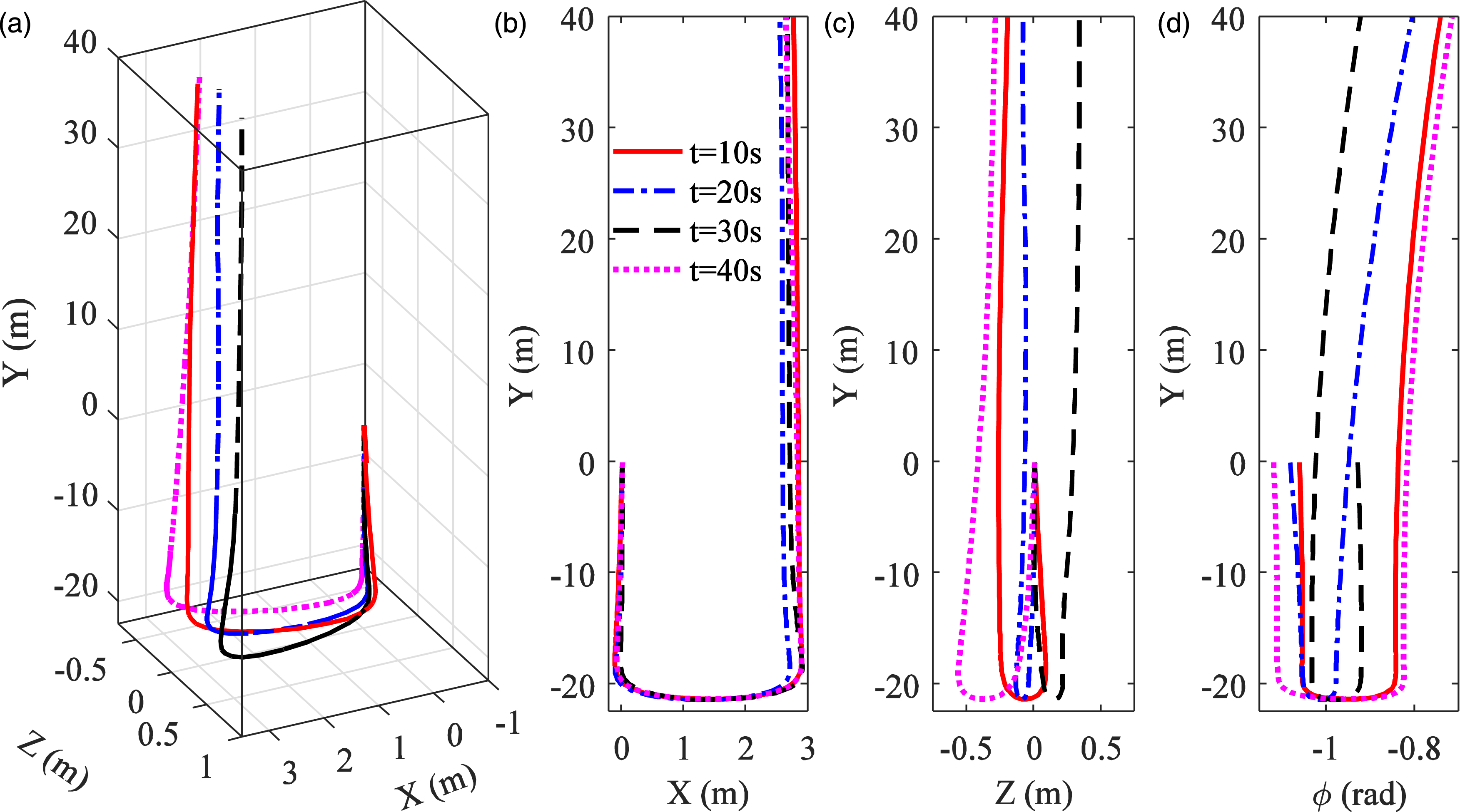
Angle acceleration, angle velocity, torsional displacement, and friction torque at right BRSR are displayed in Figures 14(a)–(d). It can be observed from Figure 14that at the moment of balance rope releasing torsional force, the angle acceleration, angle velocity, torsional displacement, and friction torque at the right end of the balance rope change dramatically and oscillate back and forth. When the torsional force of the balance rope is less than the static friction torque to be overcome, the friction between the balance rope and BRSR is static friction. Otherwise, the friction is converted to dynamic friction. At the switching instants, the friction torque and angle acceleration will also be mutated as depicted in Figures 14(a) and (d), and accompanied by slip-stick transition in angle acceleration, for instance, around t = 20 s and t = 20.8 s. Angle acceleration, angle velocity, torsional displacement, and friction torque at right BRSR.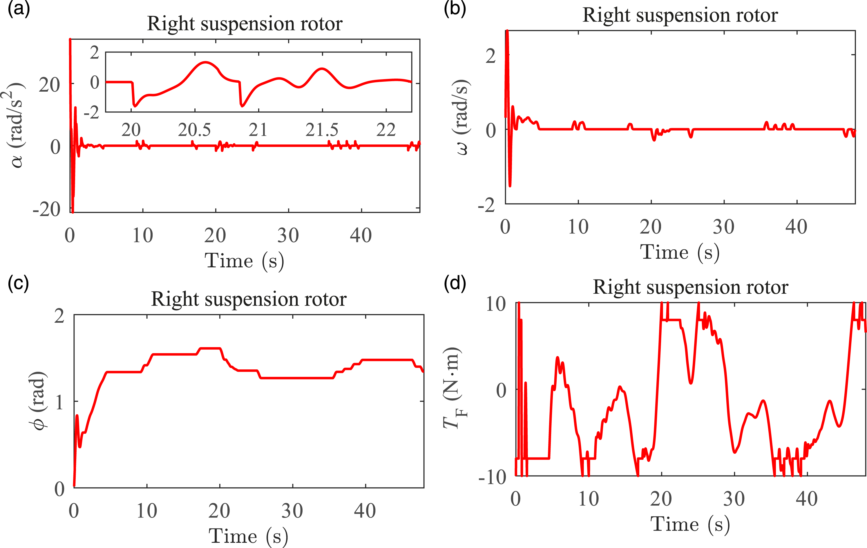
Conclusion
The torsion deformable spatial beam element and Costello wire rope theory are used to establish the longitudinal-torsional-lateral coupled dynamic model of the round balance rope in mine friction hoisting system. The nonlinear coupled dynamic model with friction constraint of the round balance rope under BRSR is proposed based on longitudinal-torsional-lateral coupled model and Coulomb’s friction law. Based on the spatial configuration characteristics of the balance rope, TMN-ETM is proposed to reduce the dimension of the dynamic equation matrix. By means of the same parameters, natural frequencies, lateral responses are compared with ANSYS and ANCF with EEM when the coupled stiffness coefficient is zero. Thereby, it can be concluded that TMN-ETM is stable and efficient.
Motion characteristics of the round balance rope without BRSR are analyzed when the coupled stiffness coefficient is not zero. The maximum torsional displacement and out-plane lateral displacement of the balance rope, caused by longitudinal-torsional coupling effect, appears at the right side balance rope loop below the balance rope. Both left and right side out-plane lateral displacements do not jump between positive and negative values during the motion of conveyance. Only about few areas in the round balance rope loop have large stress norm value and are in bending state, while the rest parts have a small stress value.
Dynamic responses of the balance rope with BRSR releasing are conducted. In the process of releasing the torsional force of the balance rope, in-plane lateral displacements of the balance rope change little, and out-plane lateral displacements and torsional displacements change violently. The out-plane balance rope loop swings back and forth from negative region to positive region. When the static friction is converted to dynamic friction, the friction torque and angle acceleration will be mutated at the switching instants, and accompanied by slip-stick transition in angle acceleration.
Footnotes
Declaration of conflicting interests
The author(s) declared no potential conflicts of interest with respect to the research, authorship, and/or publication of this article.
Funding
The author(s) disclosed receipt of the following financial support for the research, authorship, and/or publication of this article: This work was supported by the National Natural Science Foundation of China (51975571), and the Priority Academic Program Development of Jiangsu Higher Education Institutions (PAPD), China.