
Abstract
Because imbalanced power will cause the loss of the propulsion motor of the railway vehicle, and the increase in temperature will shorten the service life of the electric vehicle. Not only this but also increase the cost of electricity and maintenance. In the past, the industry only focused on methods to improve power quality such as load capacity, relay setting, and harmonic resolution. Now, the consider of three-phase unbalance rate (TPUR) must be applied. I propose special transformers wiring (STW) to improve the three unbalance rates and provide different transformer wiring methods. According to the IEEE Committee, in the future, power companies will need to install balanced relay stations to improve three-phase unbalance rate. The internal regulations of Taipower must be less than 4.5% (voltage unbalance rate (NPSUR) of 2.5% and motor temperature rise of 12.5%).
The derivation of the transformer “three-phase unbalance rate” model is the focus of the railway system. This research is based on the model derivation of different wiring methods to improve the problem caused by the three-phase imbalance and improve the using life of the train. They pointed out that Scott, Le-Blanc, and Modified-Woodbridge, the three wiring methods can be applied to future railway system and reduce the three-phase unbalance rate. They are in line with the IEEE standard (
Keywords
Introduction
The derivation of the transformer “three-phase unbalance rate” model is the focus of the railway system. In the past, railway system often studied the improvement of harmonic pollution, but ignored the existence of three-phase imbalance. This research is based on the model derivation of different wiring methods to improve the hot problem caused by the three-phase imbalance 1 and improve the service life of the train. And pointed out that Scott, Le-Blanc, and Modified-Woodbridge, the three wiring methods can be applied to future track system routes to improve the three-phase unbalance rate Figure 1.
The railway transformer power supply mode (as Figure 2), at present, the transformers used by various countries in the world are not the same. Designing a transformer, the quality of the power, has a great impact on the power supply system.
2
For power companies, voltage unbalance will affect the stability of the system’s power supply, leading to increased power consumption, resulting in increased ineffective power consumption and energy waste. Voltage fluctuations, swells or sags will reduce the life of the equipment and increase the temperature, resulting in an increase in the power consumption of the power system. The quality of the transformer has a great impact on the power supply system, and it has to be chosen carefully.
3
General three-phase balanced system circuit.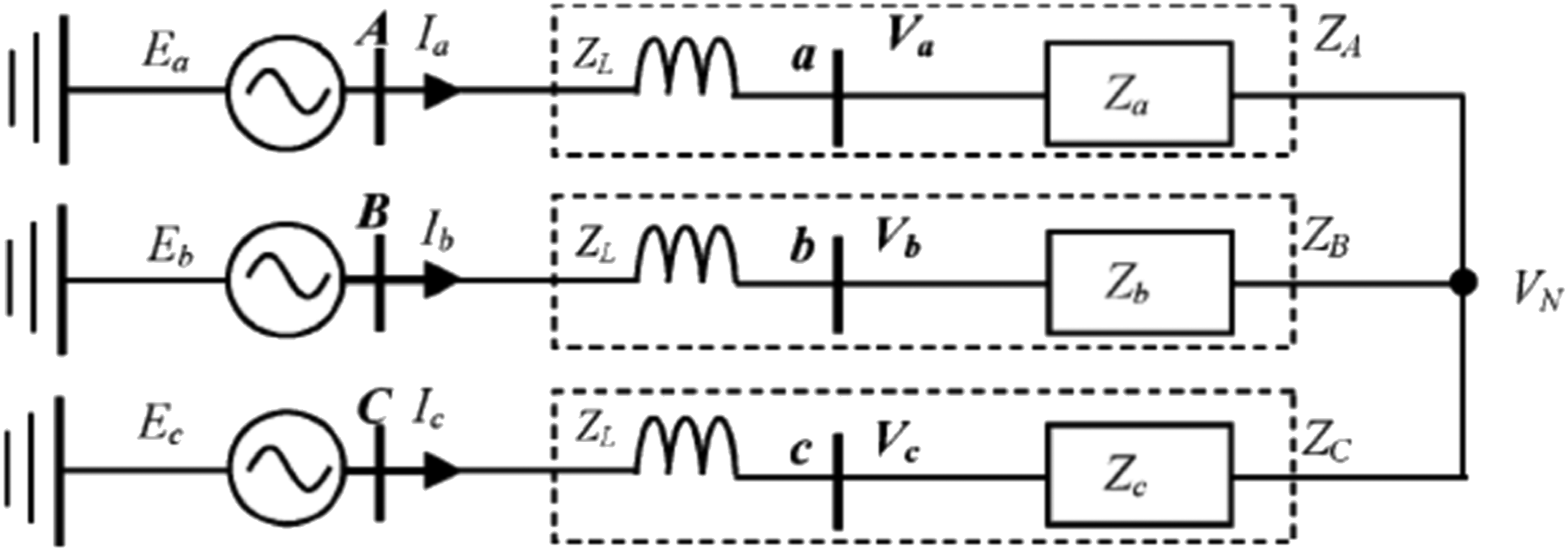
According to the IEEE Committee, in the future, power companies will need to install balanced relay stations to improve three-phase unbalance. The imbalance rate is higher than 50%, if the motor continues to operate, the motor will be only half of its life. 4 Therefore, the three-phase unbalance caused by the transformer wiring method has a great relationship with the propulsion power of the railway vehicle. To analyze the voltage unbalance rate, the negative phase sequence unbalance rate of the IEEE specification must be less than 2%, 5 you must start with the three-phase unbalance of the special transformer to see if it meets the voltage unbalance rate of less than 2% standard. To achieve the purpose of both power saving and efficiency.
How to define the voltage ungalance rate
Voltage stability is an important aspect of power supply, system operation and control. Research on Voltage Stability under the Condition of Three-phase Unbalance. In the proposed method, only one pair of solutions is calculated. Zero sequence Isolation transformer or ungrounded load. 6
The purpose of the current paper is to study multiple solutions, phenomenon of zero-sequence unbalanced network. As we all know, there are multiple solutions in the following situations Constant complex power load model, if a constant, assuming impedance load model, directly solve Neutral point voltage is possible.
The voltage can be calculated as follows


The definition of voltage unbalance rate varies from country to country, and the calculation formulas are also different. In this chapter, three types are proposed for comparison. 1) The NEMA expression for voltage imbalance is often referred to as the Line Voltage Unbalance Rate (LVUR) and described (NEMA) 2) The IEEE identification of imbalance voltage, moreover called so the “Phase Voltage Unbalance Rate (IEEE),” is given by


Max: maximum, V3L: Average value of three-phase line voltage, V3PD: Average value of three-phase phase voltage. 3) The IEC identification of voltage unbalance moreover termed the exact identification of imbalance voltage is defined: “The percentage voltage unbalance factor (IEC)”

Vn: Positive sequence voltage component, Vp: Negative sequence voltage component, Vn、 Vp: Calculated by Symmetric Component Analysis.
According to IEEE regulations, the three-phase unbalance rate needs to be within 2%, and other calculation formulas can be applied

Derivation of voltage unbalance rate of special transformer
Special transformer wiring is divided into V-V wiring, Scott wiring, Le-Blanc wiring, Modified-Woodbridge wiring, and Star-Zigzag wiring. Because the electric vehicle is a three-phase unbalanced load, most of the voltage unbalance is caused by the incomplete transposition of the three-phase unbalanced load on the transmission line,
7
so the system unbalance rate is mostly caused by the three-phase unbalanced load. In order to solve this problem, the railway traction power substation can consider using a special transformer wiring method to improve the three-phase unbalance problem.
8
Simplified from Figure 2 to Equivalent Circuit Figure 2. Schematic diagram of transformer equivalent circuit.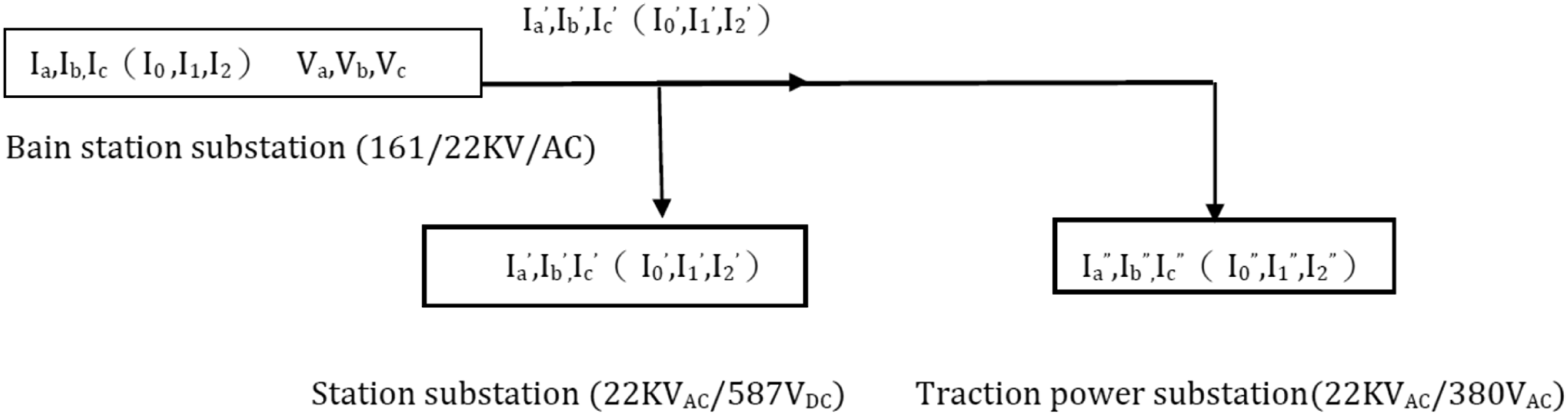
Here we define

A. Scott wiring transformer
Scott Transformers are used in non-grounded systems in England and Japan. The Scott transformer connection method is shown in Figure 3.
9
Scott transformer wiring diagram.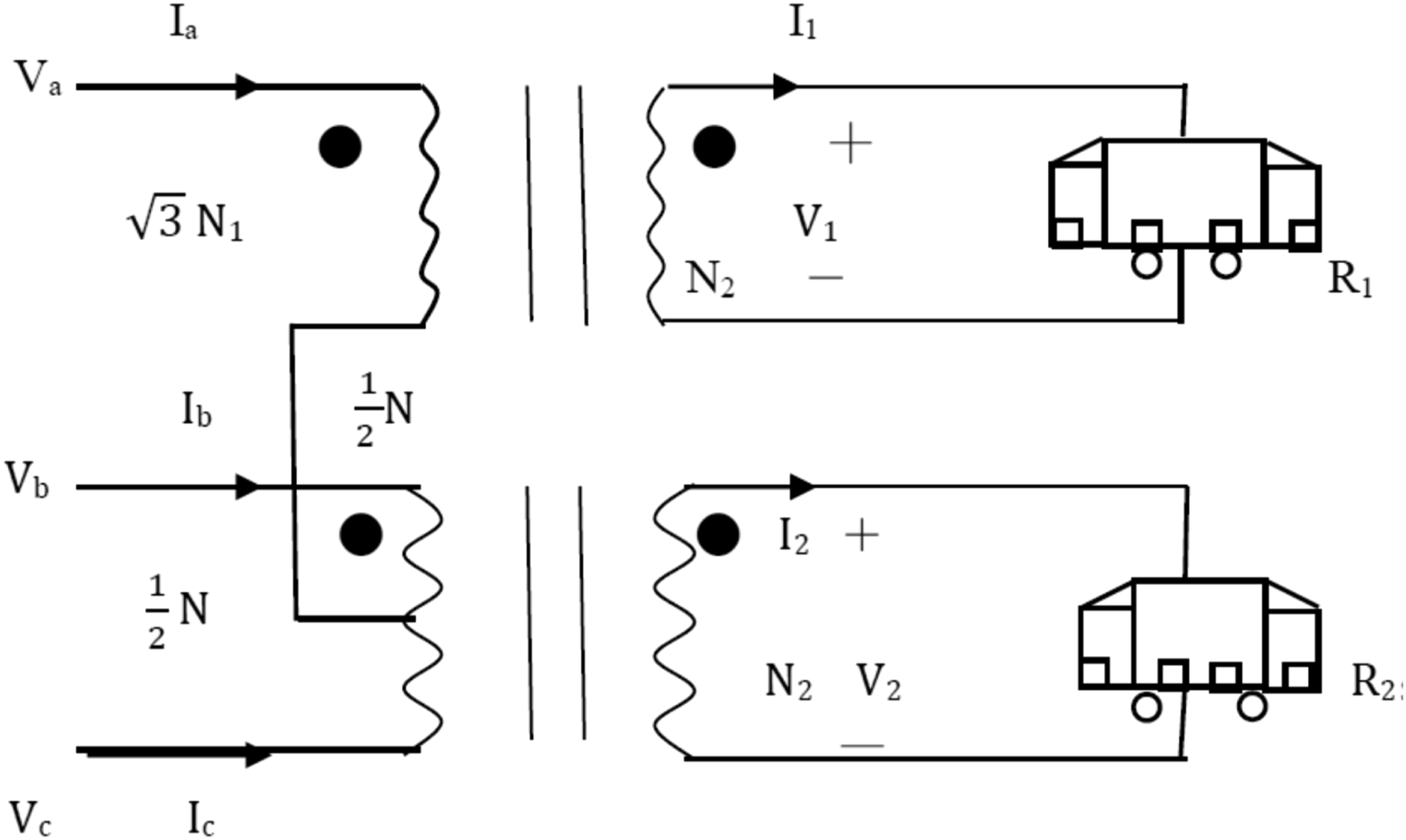
B. Le-blanc wiring transformer
Le-Blanc transformer is used in German railway system, and its Le-Blanc transformer connection method is shown in Figure 4. Le-Blanc transformer wiring diagram.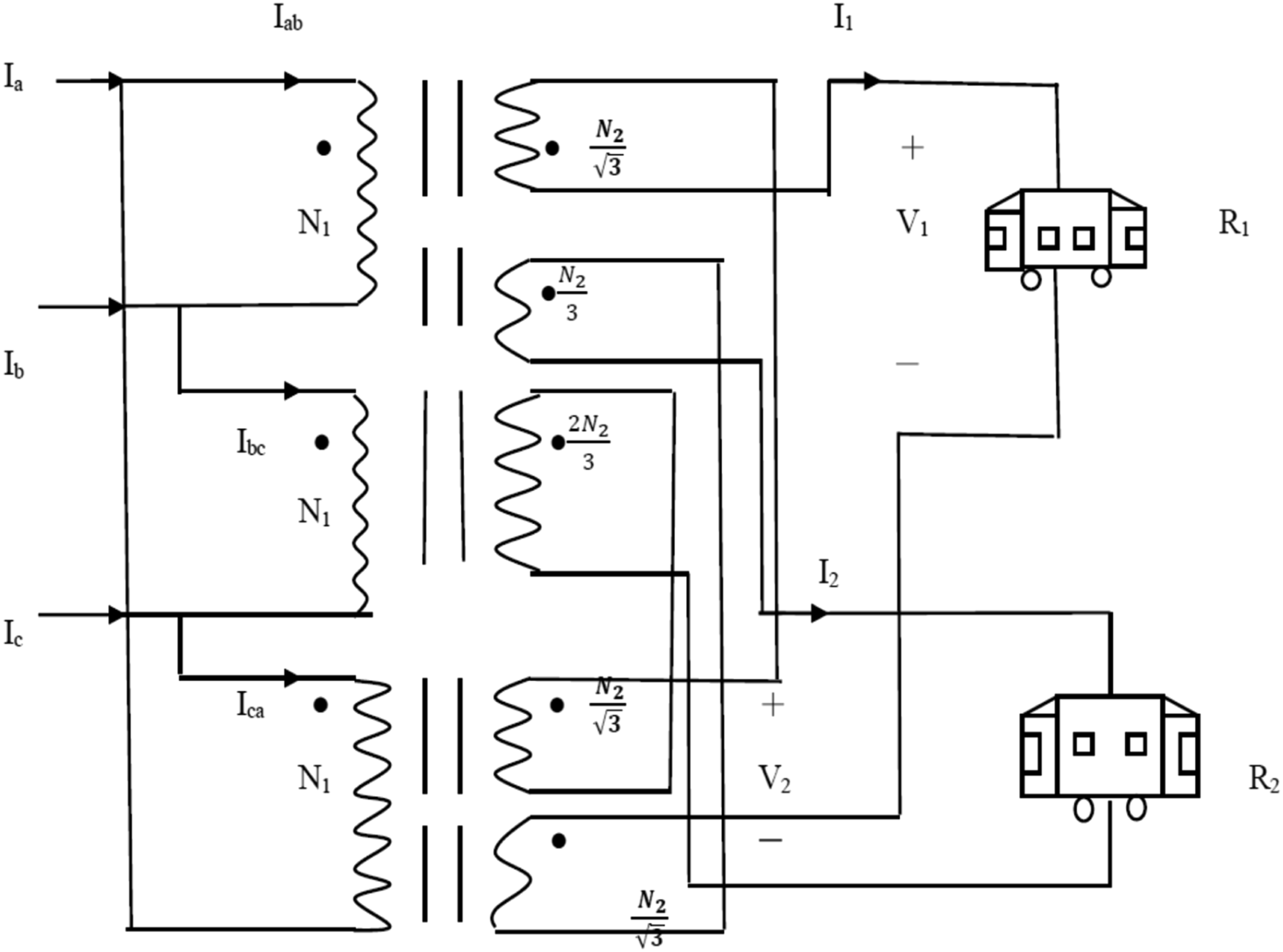
C. Modified-woodbridge wiring transformer
Modified-Woodbridge transformer is used in Japanese grounding system, and its transformer connection method is shown in Figure 5. Modified-Woodbridge transformer wiring diagram among them 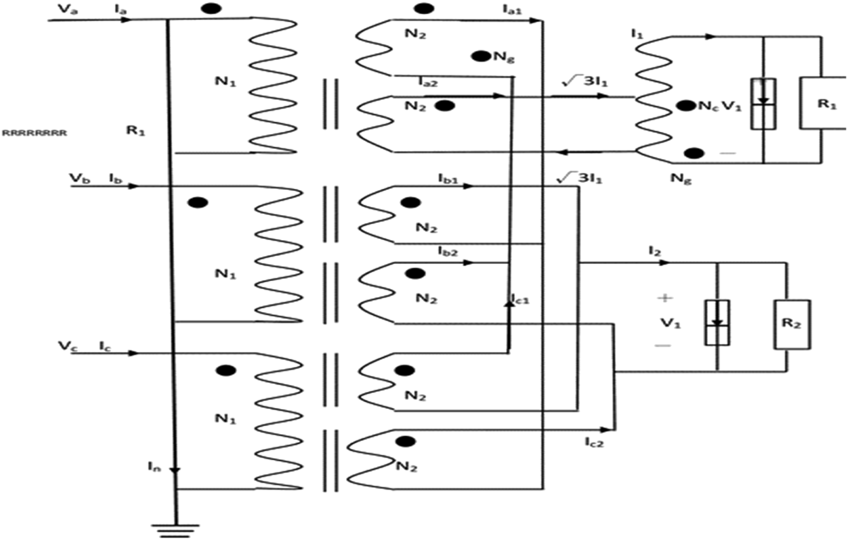
Relational derivation of three special wiring transformers
A. Scott wiring transformer derivation
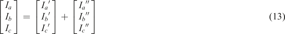
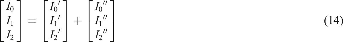
The relationship between Scott wiring transformers calculated according to Figure 4 is as and from (13) (14)


Important discussion: This situation is likely to be greater than 2% of the IEEE international standard, which is less suitable for railway TSS power.
B. Le-blanc wiring transformer relational derivation
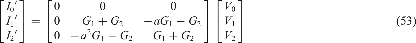
The relationship between Le-Blanc wiring transformers calculated according to Figure 5 is as follows
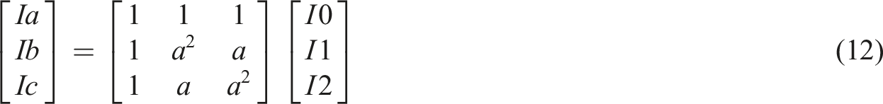
The three-phase symmetrical component matrix is
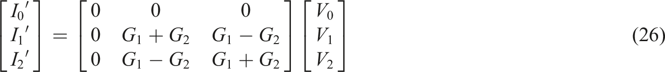

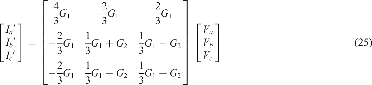
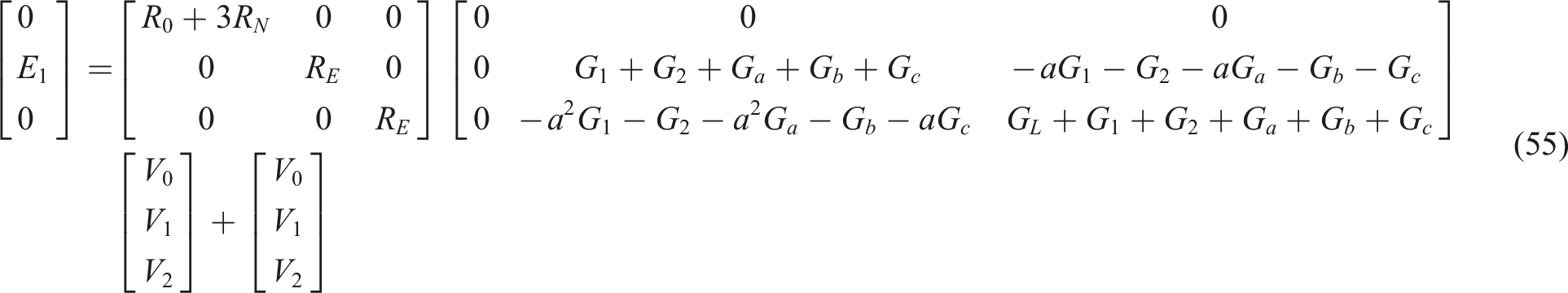
Will Le-Blanc the connection equations (14), (23), and (24) of the wiring transformer are substituted into the three-phase line-to-ground voltage formula (25)

Got

Among them, positive phase sequence voltage of voltage source, self-inductance, mutual inductance, impedance of voltage source to ground,


discuss focused on:
Usually GS >> G1, G2, if the denominators G1 and G2 are ignored, then (29) is

C. Modified-Woodbridge relational derivation of wiring transformer
The relationship between Modified-Woodbridge wiring transformer calculated according to Figure 6 is as follows Wiring diagram of single-phase transformer.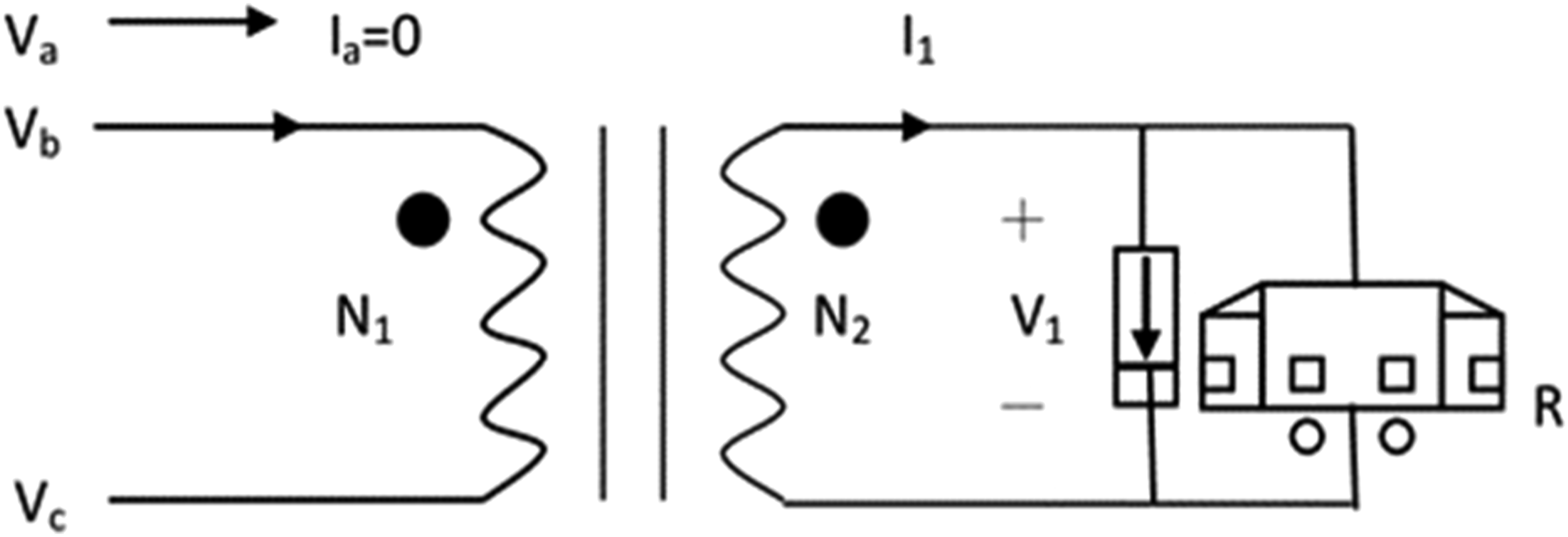
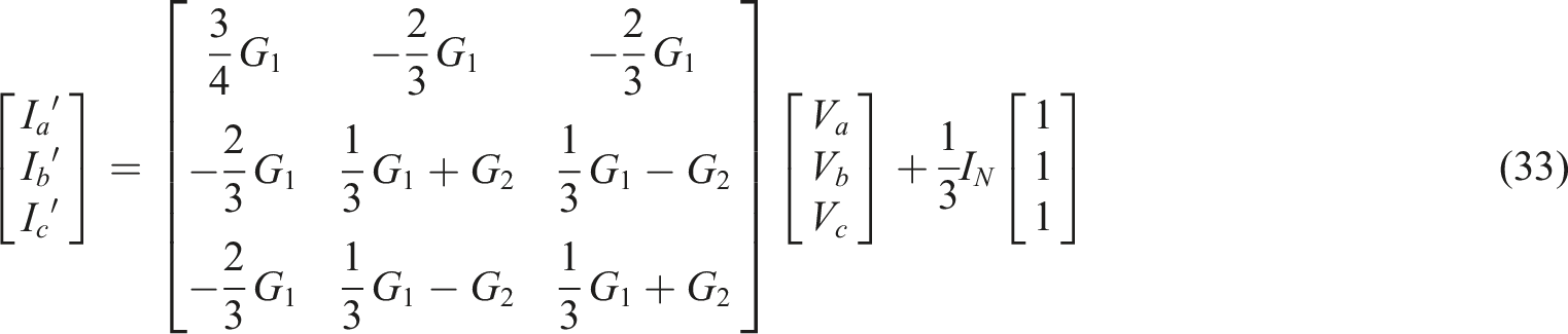
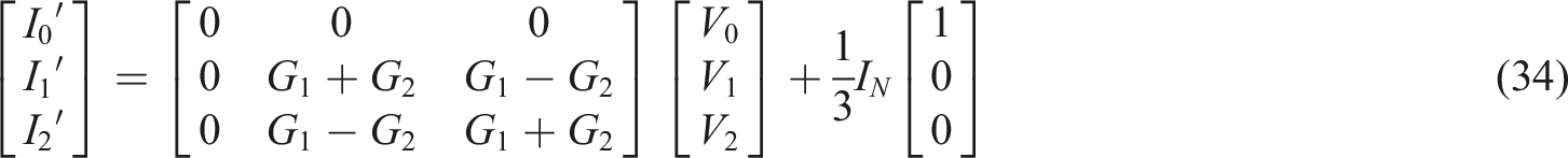
Substitute the relational expressions (33), (34), and (27) of the Modified-Woodbridge wiring transformer into the three-phase line-to-ground voltage formula (35)
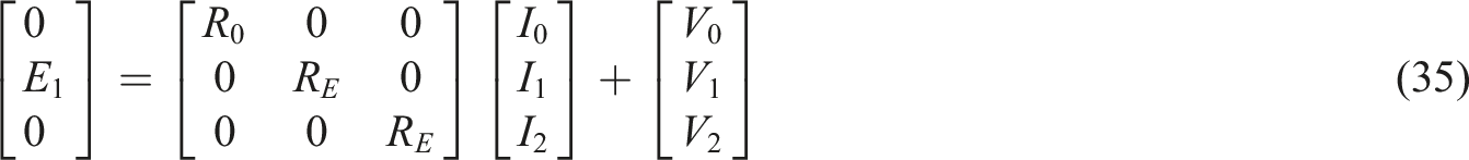
Got

Among them, positive phase sequence voltage of voltage source, self-inductance, mutual inductance, and impedance of voltage source to ground;
It is known from the symmetrical component analysis method that the three-phase unbalance rate is


discuss focused on:
Usually GS >> G1, G2, if G1 and G2 are ignored, then (38)
Got 1) From equations (26) and (16), it can be seen that Scott/Le-Blanc wiring transformer and Modified-Woodbridge wiring transformer ignore the three-phase load (i.e., no-load) and G1, G2; the same. 2) In this way, GS >> G1, G2, and the molecules are very small, so the three-phase unbalance rate is less than 2%, and the probability is very high. It is one of the ways to consider for traction power substation of railway system.
11

Derivation of voltage unbalance rate for traditional transformer and V-V wiring star-zigzag wiring
Traditional transformer wiring is divided into single-phase wiring and three-phase Wye-Delta wiring. Because Taipower adopts a central feeding system, on single-phase wiring transformers, the power source with a feeding point is strong, and the substation also has the favorable factor of small traction load, which is easier in emergency or maintenance. At present, the Taiwan Railway Bureau uses this system. The railway system does not use single-phase wiring transformers because of large harmonic problems and excessive reactive power. 12
A. Single-phase wiring transformer
Single-phase wiring transformer is used in Italian railway system, New Zealand railway system, Taiwan railway system, and its transformer connection method is shown in Figure 6.
From the calculation in Figure 6:
In

Simplified

Among them, the symmetric component analysis method shows that the three-phase unbalance rate is


Usually GS >> G. If the denominator G is negligible, then is

It is impossible to judge whether the three-phase unbalance rate will exceed the international standard of 2% under no load. 13
B. Three-phase Wye-Delta wiring transformer
Three-phase Wye-Delta wiring transformers are used in mainland China MRT and railway systems, Taipei MRT Tamsui Xindian line, and the transformer connection method is shown in Figure 7. Wiring diagram of three-phase Wye-Delta transformer.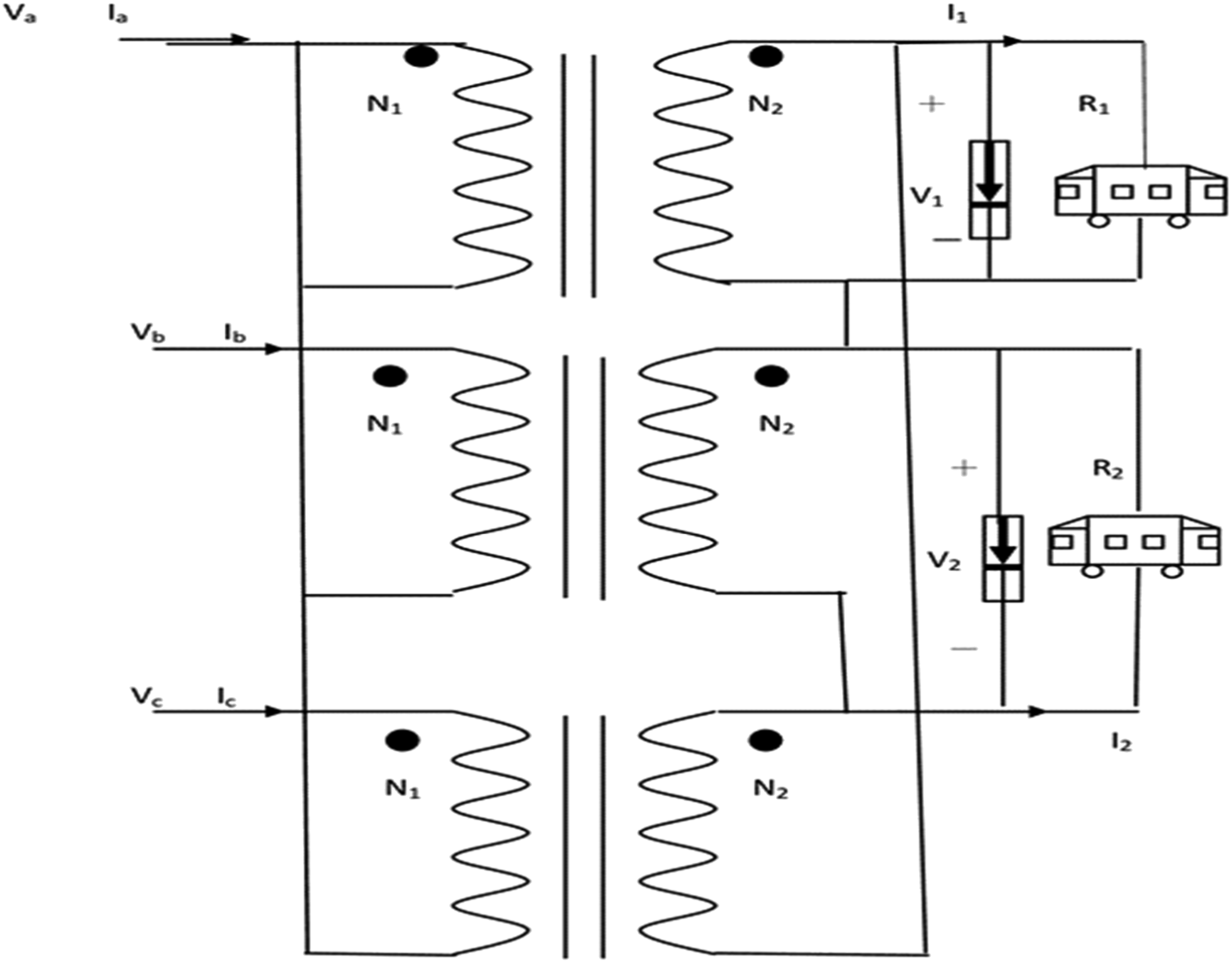
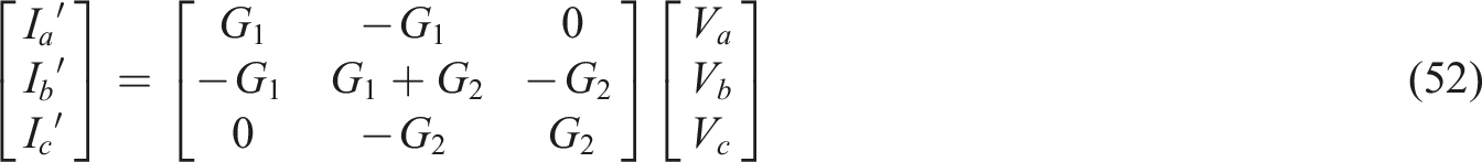
According to Figure 7, the three-phase Wye-Delta calculation shows that the relationship of the wiring transformer is as follows
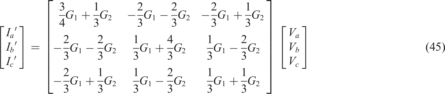
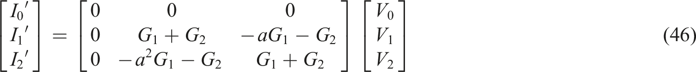
Substitute the relational expressions (45), (46), and (47) of the three-phase Wye-Delta wiring transformer into the three-phase line-to-ground voltage formula
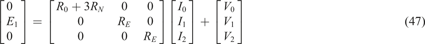
Got

It is known from the symmetrical component analysis method that the three-phase imbalance rate is


Usually GS >> G1, G2, if the denominators G1 and G2 are negligible, then (46)
Got (1) The wiring mode of three-phase Wye-Delta wiring is that the power at the feed point is weak, the substation has a large load, and emergency or maintenance is not easy, but because the MRT station is very short, and there are traction power substations about every two stations. In emergency situations or maintenance, there are 24 h of personnel on standby, and the replacement of spare parts is fast, which can make up for the shortcomings of the three-phase Wye-Delta wiring in this regard. (2) There is a three-phase imbalance problem in this wiring method. According to the calculation in (51), the molecule has an operator, and it is easy to produce an unbalance rate greater than 2%, so there is room for improvement. (3) Three-phase Wye-Delta wiring produces less harmonics than single-phase wiring.
14

C. V-V wiring transformer
V-V transformer is used in the national railway system of Finland, and its V-V transformer connection method is shown in Figure 8. V-V transformer wiring diagram.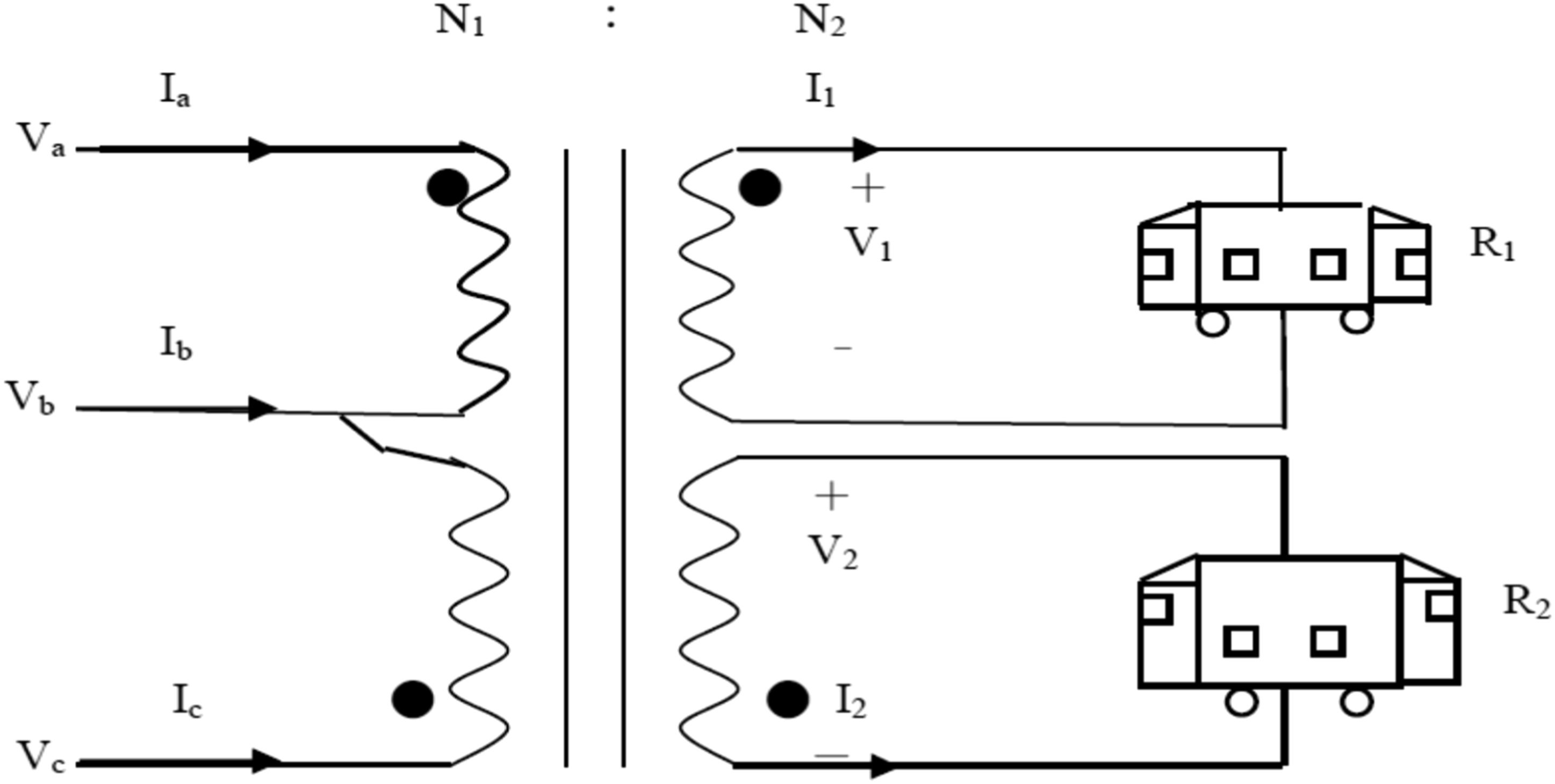
From the calculation in Figure 8 and from (20) (21)
From the three-phase line-to-ground voltage formula

Substituting (14), (49), and (50) into (51) gives


Important discussion: This situation is likely to be greater than 2% of the IEEE international standard, which is less suitable for power of railway system
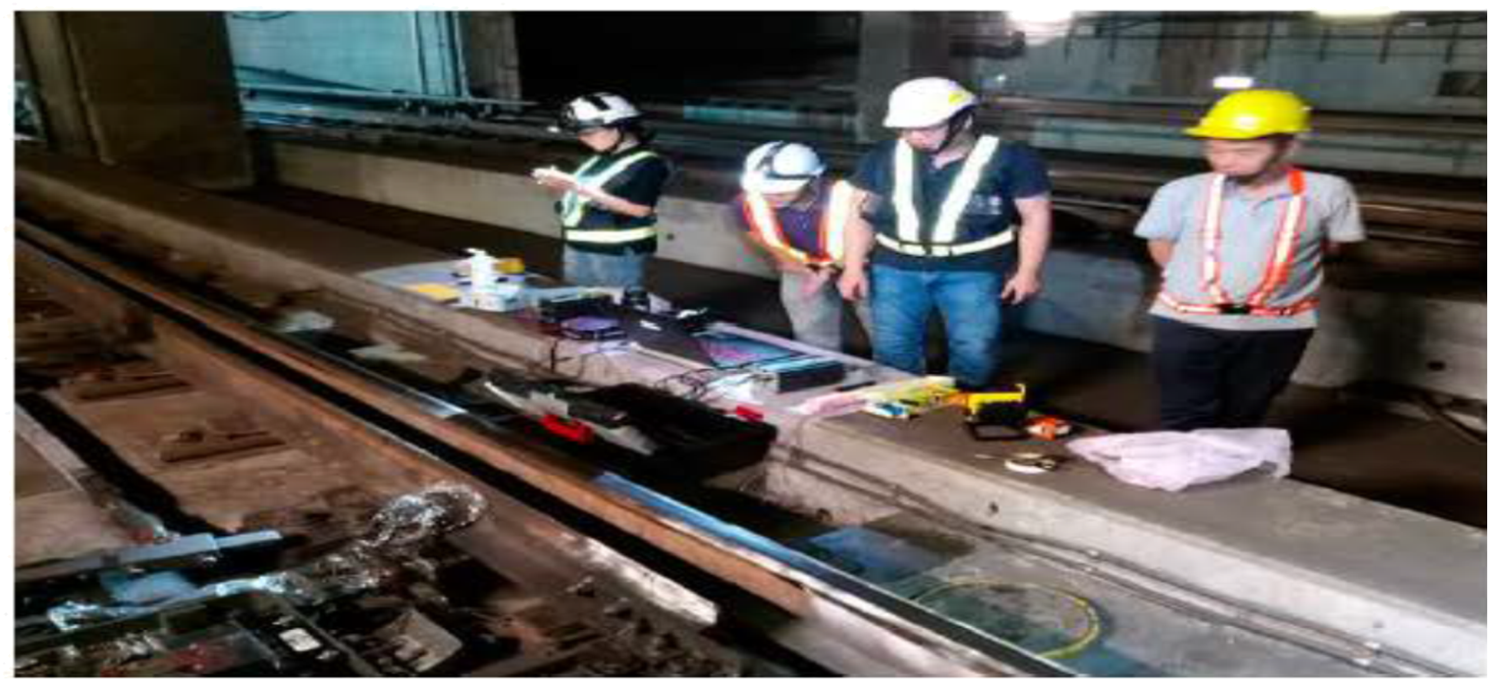
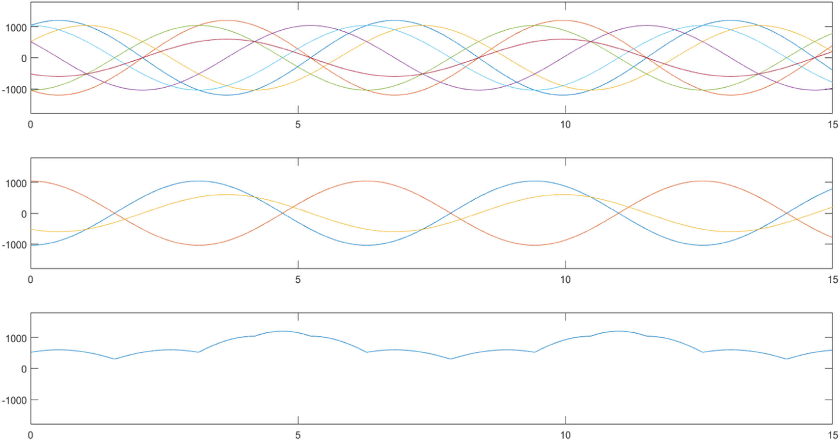
Taiwan high-speed railway adopts V-V connection, its three-phase unbalance rate is very high and over than 2%, there is still a lot of room for improvement (Figure 9, 10, and 11) 161KV voltage wire. Field potential measurement. 3 phase actual measurement imbalanced potential curve diagram.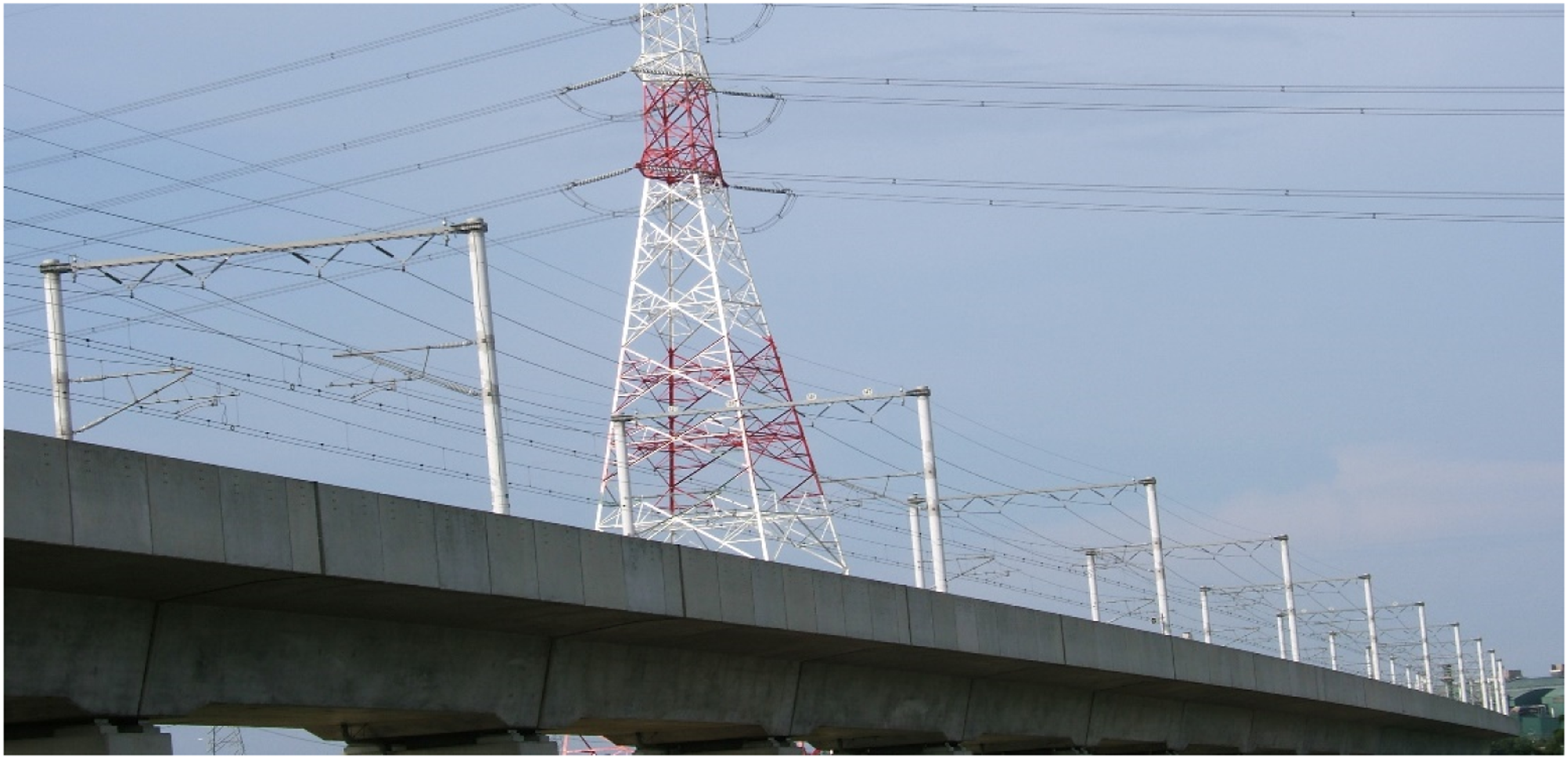
D. Star-Zigzag wiring transformer
The Star-Zigzag transformer is applied to the British subsea tunnel system, and its transformer connection method is shown in Figure 12. Star-Zigzag transformer wiring diagram.
The relationship
15
of Star-Zigzag wiring transformer calculated according to Figure 12 is as follows

Among them
Substitute the relational expressions (59), (60), and (27) of the Star-Zigzag wiring transformer into the three-phase line-to-ground voltage formula (64)
Got

Among them, positive phase sequence voltage of voltage source, self-inductance, mutual inductance, impedance of voltage source to ground;
It is known from the symmetrical component analysis method that the three-phase unbalance rate is


Usually GS >> G1, G2, G3, if the denominators G1, G2, G3 are negligible, then (65)
Got

Important discussion: This involves the angle of the operator. The molecules G1, G2, and G3 cannot be omitted, and the three-phase unbalance rate is easy to exceed 2%, so it is not suitable for power of railway system. 15
Conclusion
Comparison table of three-phase unbalance rate.
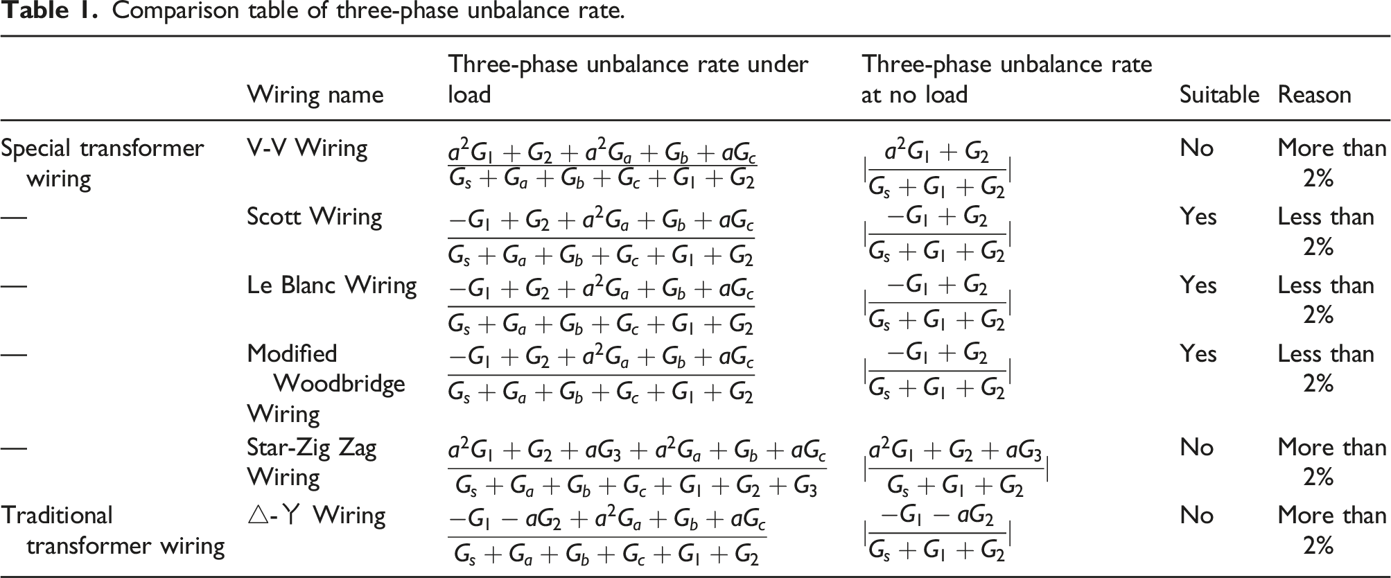
The three-phase balanced circuit will have sin and cos waveforms as shown in the simulation Figure 13, and the three-phase unbalanced circuit will have non-sin and cos waveforms as shown in the simulation Figure 14. If V-V Wiring, Star-Zig Zag Wiring is used, there will be generate irregular voltage waveforms, and long-term power supply for train driving will increase the temperature of the train, resulting in shortened service life and costing the company. 3 phase balanced potential simulation curve diagram. 3 phase imbalanced potential simulation curve diagram.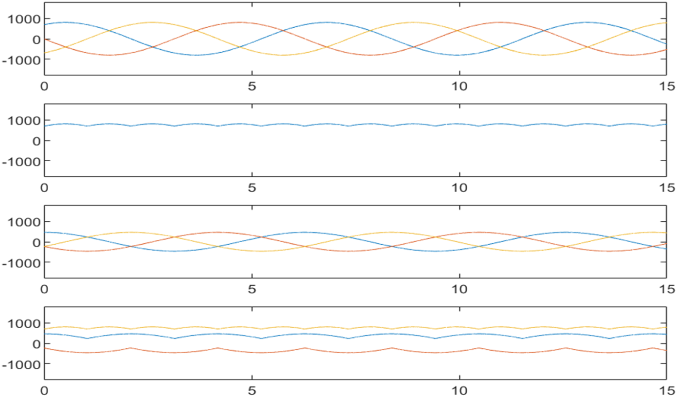
(e). 3 phase balanced potential simulation curve diagram. (f) 3 phase imbalanced potential simulation curve diagram.
Scott, Le-Blanc, and Modified-Woodbridge have improved the three-phase unbalance problem. This is a good situation, but because it is a special transformer wiring method, there is still little related experience and research, and there is still room for research on the protection of fault current relays. Of course, we hope that the smaller the short-circuit current, the better, and the smoother the power flow distribution.
In this way, the protection relay setting is simpler and the failure rate is smaller. The three usage rates in various countries in the world are not universal, and are generally designed and manufactured by the manufacturers themselves. Therefore, the impedance of the transformer is not a fixed value, and it depends on the material and the number of winding turns.
Footnotes
Declaration of conflicting interests
The author(s) declared no potential conflicts of interest with respect to the research, authorship, and/or publication of this article.
Funding
The author(s) received no financial support for the research, authorship, and/or publication of this article.