
Abstract
In this paper, a dynamics model of the gear-bearing transmission system with bending and torsion coupling is established, and the influence of gear shifted on the vibration characteristics of the gear system is considered. First, the time-varying mesh stiffness of the profile shifted gear is derived by using the potential energy method. Then, based on the Lagrange equation numerical method, the vibration differential equation of the model is obtained, and the differential equation is solved by the fourth-order Runge-Kutta method. Finally, the influence of the profile shifted coefficient and input torque on the vibration characteristics of the gear transmission system is analyzed by using the time domain graph and the frequency domain graph. The conclusions drawn from this study can help engineers better understand the running performance and vibration characteristics of profile shifted gear.
Introduction
Gear transmission is widely utilized in aerospace, wind power generation, and other industries as one of the most frequently used mechanical transmission technologies. External excitations such as rotational speed and torque, together with internal excitations such as time-varying meshing stiffness, tooth side clearance, and transmission faults, cause the gear system’s dynamic behavior to become more complex. As a result, gear system dynamics and the factors that influence them have become a major research topic.
Time-varying meshing stiffness is one of the most important internal excitations that cause vibration and noise in gear transmission systems. At present, many scholars have used finite element method, analytical method, and loaded tooth contact method 1 to calculate the time-varying mesh stiffness of gears. Baishun Zhao et al. 2 established a dynamic model considering the influence of geometric eccentricity by using the load-tooth contact method. Qibin Wang 3 and Kangkang Chen 4 have established a finite element model of time-varying mesh stiffness of cylindrical spur gears considering the effect of complex matrix and cracks to investigate the effect of the web width and bore diameter on the time-varying mesh stiffness of gears. Shuo Feng et al. 5 combined finite element method and analytical method to solve time-varying meshing stiffness of inner gear pair and investigated its influence on ring thickness. Through finite element modeling, Siar Deniz Yavuz et al. 6 studied the complex dynamic behavior of the transmission system including parallel shaft gear and cross shaft gear. Jiaxing Zhang et al. 7 developed a finite element method for determining time-varying meshing stiffness of gears based on some commercial software, and analyzed the influence of gear teeth misalignment on stiffness. Considering the influence of gear cracks and drive shaft cracks on the gear transmission system, Yong Shen et al. 8 calculated the time-varying meshing stiffness of gear by finite element method and analyzed the dynamic response of different faults. Although the finite element method is more accurate in solving the time-varying gear mesh stiffness, however, it takes too long to calculate the solution and causes unnecessary waste of time, so most scholars prefer to use the analytical method. Del Rincon A F et al. 9 presented a method to calculate the meshing stiffness and loaded transmission error. At the same time, the friction and the possibility of contact were considered. Hui Ma et al. 10 proposed an analytical model of time-varying meshing stiffness of cylindrical spur gears considering extended meshing and modified fillet-base stiffness and analyzed the effects of different modification parameters on the stiffness of the gear system. Chongyang Xie et al. 11 established a time-varying meshing stiffness model with tooth profile error by considering the influence of coupling flexibility between adjacent gear teeth. Zaigang Chen et al. 12 established an improved gear analysis model by considering the effects of tooth deformation and tooth profile deviation and revealed the mechanism of the effect of tooth body structure coupling on gear tooth meshing stiffness. Jinhai Wang et al. 13 proposed a time-varying meshing stiffness calculation model for displacement gears and investigated the effect of displacement coefficient on gear tooth stiffness. Zaigang Chen et al. 14 established a time-varying meshing stiffness model for internal profile shifted gear pairs based on the potential energy principle. Zhifang Zhao et al. 15 established a fractal contact model considering the influence of tooth surface roughness on gear pair and studied the influence of roughness and tooth surface sliding friction on time-varying meshing stiffness. Diez-Ibarbia A et al. 16 proposed a model to assess the energy efficiency of the spur gear and investigated the effect of the profile shifted coefficient on efficiency.
The dynamic characteristics of the gear system are very complicated, so it is significant to study the mechanism of its influence on the healthy operation of the system. Zhao Weiqiang et al. 17 investigated the vibration characteristics of a pitting fault gear transmission system considering the effects of eccentricity and friction. Zheng Cao et al. 18 proposed a cylindrical spur gear dynamics model considering the effects of time-varying meshing stiffness, tooth clearance and tooth misalignment. Weiwei Liu et al. 19 established the high-speed gear transmission system of wind turbine considering the influence of electromagnetic torque disturbance and eccentricity, and analyzed the influence of electromagnetic torque disturbance on the dynamic response of the system. Sha Wei et al. 20 established an uncertain single-stage gear dynamic model to investigate the effect of uncertain parameters to the system, and the results were verified by experiment. Yong Yi et al. 21 established a nonlinear model of gear transmission system considering time-varying pressure angle and tooth gap, and the dynamic characteristics of the system were investigated with tooth gap as the control variable. Wenchao Mo et al. 22 established a dynamic model of a helical gear transmission system considering the influence of sliding friction and gear error and studied the influence of gear error on the vibration characteristics of the system. Considered the gear eccentricity and nonlinear bearing force, Xiang et al. 23 investigated the effect of gear eccentricity and rotational speed on the gear system.
In summary, the majority of recent research has focused on the normal cylindrical spur gear system, whereas with no consideration of the effect of gear profile shifted on the gear transmission system. In this paper, a nonlinear dynamics model of a 16-degree-of-freedom gear-rotor-bearing transmission system is established, the time-varying mesh stiffness of the profile shifted gear is computed by using the potential energy principle, the nonlinear differential equations are obtained by using Lagrange’s equation, and the differential equations are solved using the fourth-order Langer-Kutta method in this paper. The effects of the profile shifted coefficient and input torque on the dynamic characteristics of the gear system are investigated.
Time-varying meshing stiffness of profile shifted gears
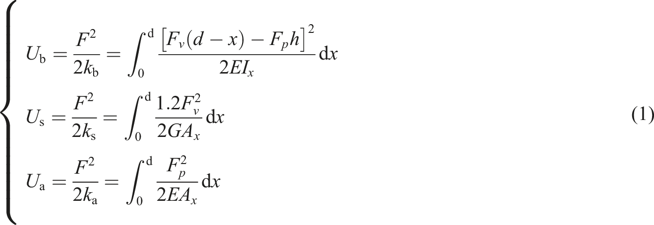
The most dominant source of internal excitation for gear vibration noise is time-varying meshing stiffness, which has a straightforward impact on gear operational life. As a result, accurate estimation of time-varying meshing stiffness is critical for researching gear dynamic characteristics. In this paper, based on the potential energy principle, the gear tooth is simplified to a variable-section cantilever beam. As illustrated in Figure 1, its bending energy, shear energy, and axial compression energy are computed as follows: Spur gear cantilever beam model.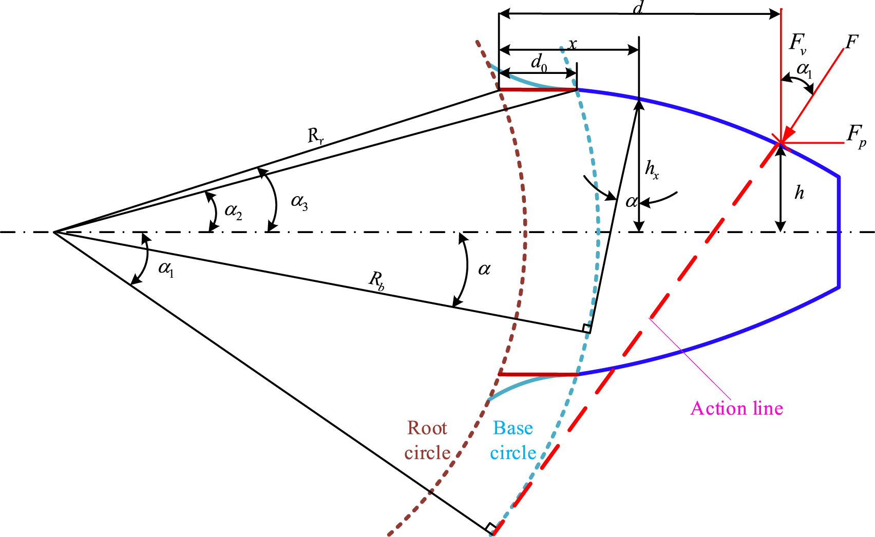
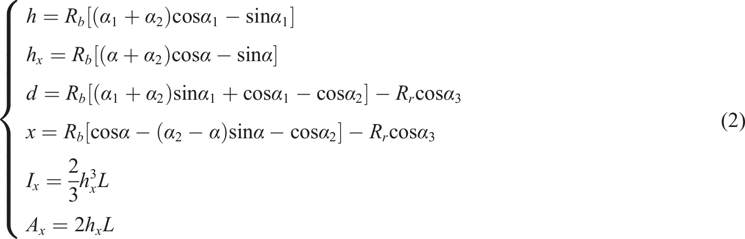
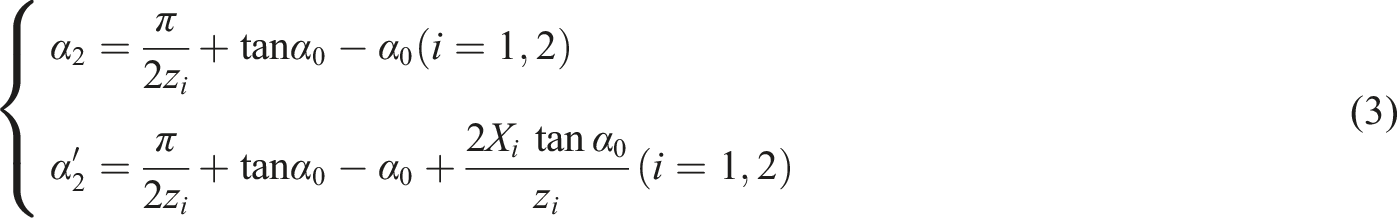
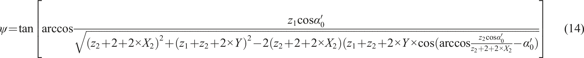
When the gear is shifted, Engagement angle of the profile shifted gear.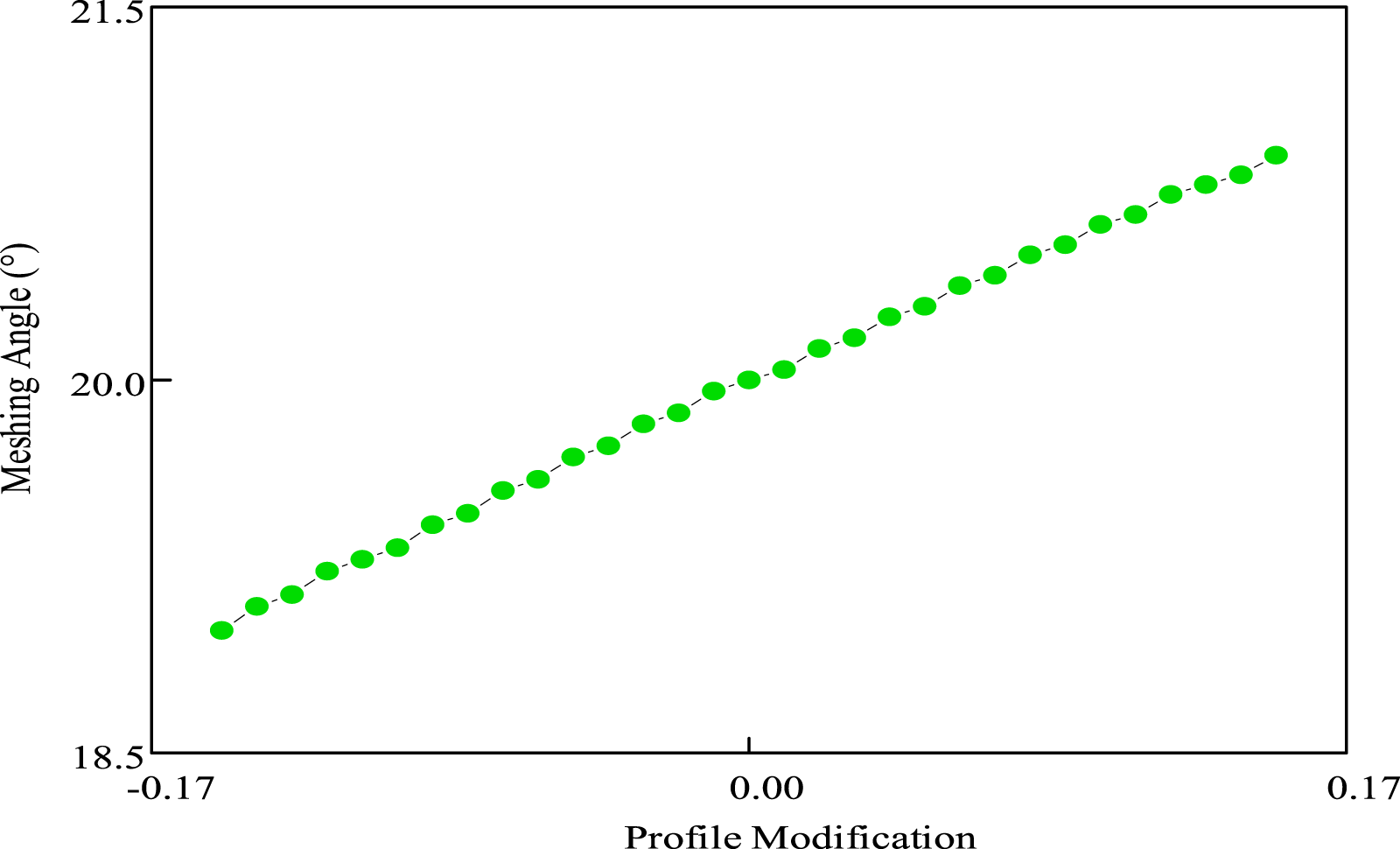

The center distance of the gear will also change accordingly with the change of the profile shifted coefficient, and the center distance of the gear after the shifting is as follows:


The time-varying mesh stiffness of gears is solved based on the energy method, bending stiffness kb, shear stiffness
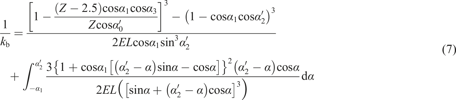
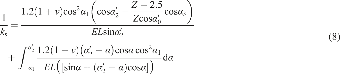
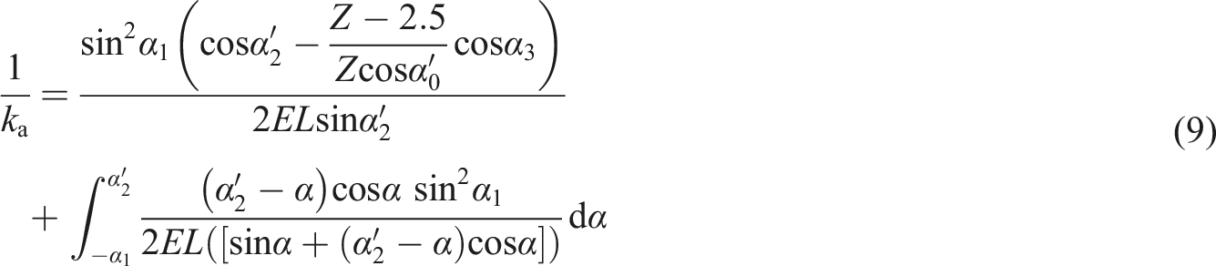
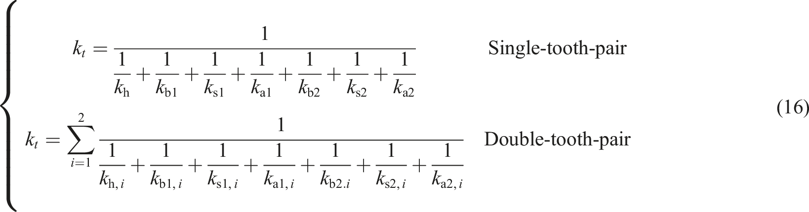
Due to the phenomenon of alternating single and double tooth meshing in the process of gear meshing, therefore,


The Hertz contact stiffness of the gear pair is calculated as follow:
24

Combining equations (7)–(15), the total time-varying meshing stiffness of the gear pair is calculated as follows:
The time-varying meshing stiffness of the profile shifted gear is shown in Figure 3, from which it can be seen that the time-varying meshing stiffness increases with the increase of the shifting coefficient when the gears take positive shifting, and the changes is nonlinear, while the double-tooth meshing duration decreases and the single-tooth meshing duration increases. This is because the gear overlap ratio decreases when the gear is in positive transmission, and the tooth thickness of the positive transmission gear increases compared to the standard gear. The opposite result is obtained when the gears are negatively shifted, and the magnitude of the time-varying meshing stiffness decreases as the absolute value of the shifting coefficient increases, while the double meshing duration increases and the single meshing duration decreases. Time-varying meshing stiffness of profile shifted gears. (a) Positive shifted transmission. (b) Negative shifted transmission.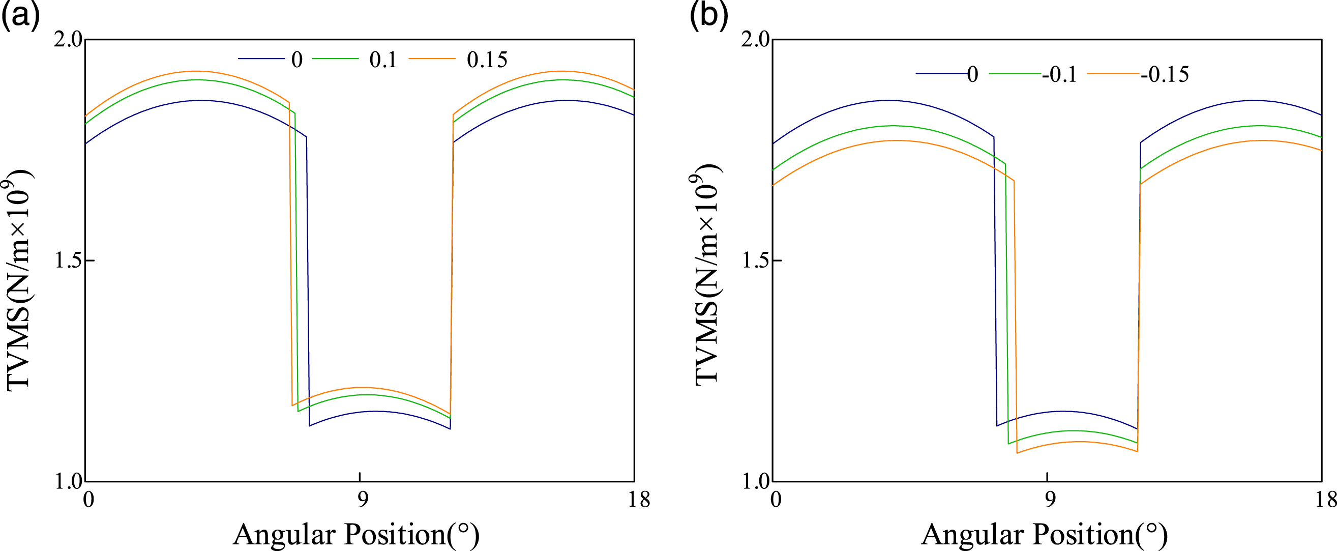
Dynamic model
The dynamic model of the gear system
For the convenience to illustrate, a diagram of the structure of the gear-bearing transmission system is shown in Figure 4. The system is symmetrically arranged with the gear shaft, utilizing deep groove ball bearings as the support of the gear shaft, and ignoring the effects of installation errors and thermal deformation of each part. For this structural diagram, a multi-degree-freedom bending-torsion coupled gear-rotor-bearing transmission system centralized mass dynamics model considering profile shifted and friction is established in this paper, as shown in Figure 4. The structural diagram of the gear-rotor-bearing transmission system.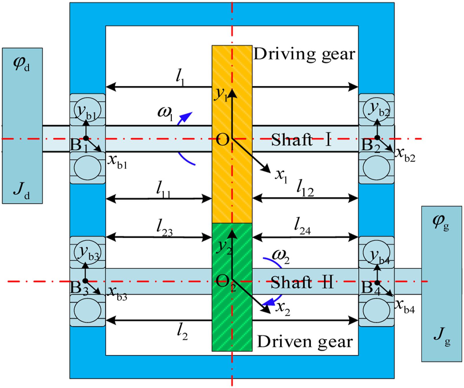
In Figure 4, O1, O2 are, respectively, represent the theoretical rotational center of the driving gear and driven gear,
In Figure 5, m1 and m2 are the mass of the driving and driven gear, G1 (xg1, yg1) and G2 (xg2, yg2) are the center-of-mass coordinate of the gear. Eccentric distances of gear pair are ρ1 and ρ2, in addition, ρ2 = 2ρ1. rb1 and rb2 are the radii of the base circles. The moment of inertia with reference to the center of mass is J1 and J2. Dynamics model of bent-torsion coupled gear-rotor-bearing transmission system.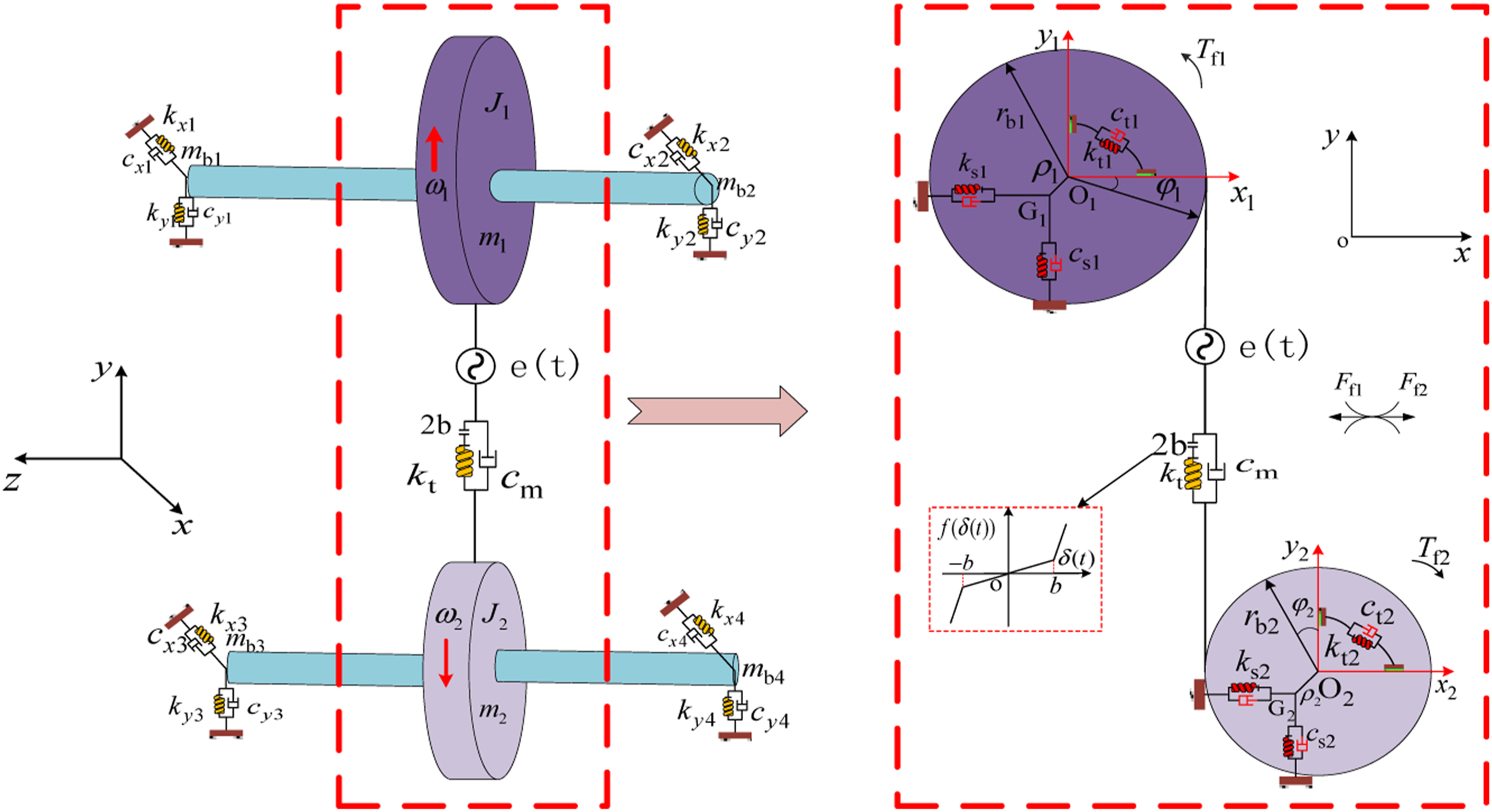
As shown in Figure 5, The angular displacement generated by the flexible vibration of the gear, including the input/output, driving/driven gear, are assumed to be


The elastic deformation of the gear drive shafts in the direction of rotation as follow:
Dynamic transmission error between two meshing gears is defined as

During the gear meshing operation, the dynamic meshing force Fm was specified as:

Figure 6 is a diagram of the gear pair meshing. In Figure 6, the meshing point is M, Diagram of the gear pair meshing.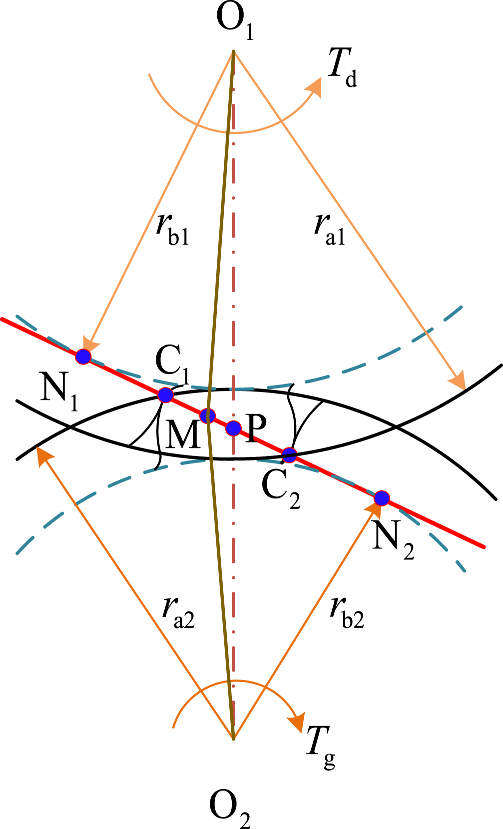


The dynamic of the ball bearing
Figure 7 is the diagram of the ball bearing. The outer ring of the bearing has interference fit on the bearing seat, and the inner ring has also interference fit with the shaft, and the balls are evenly arranged between the inner and outer rings. It can be ignored the centrifugal force of the balls. The deformation of the ball can be express as The diagram of the ball bearing.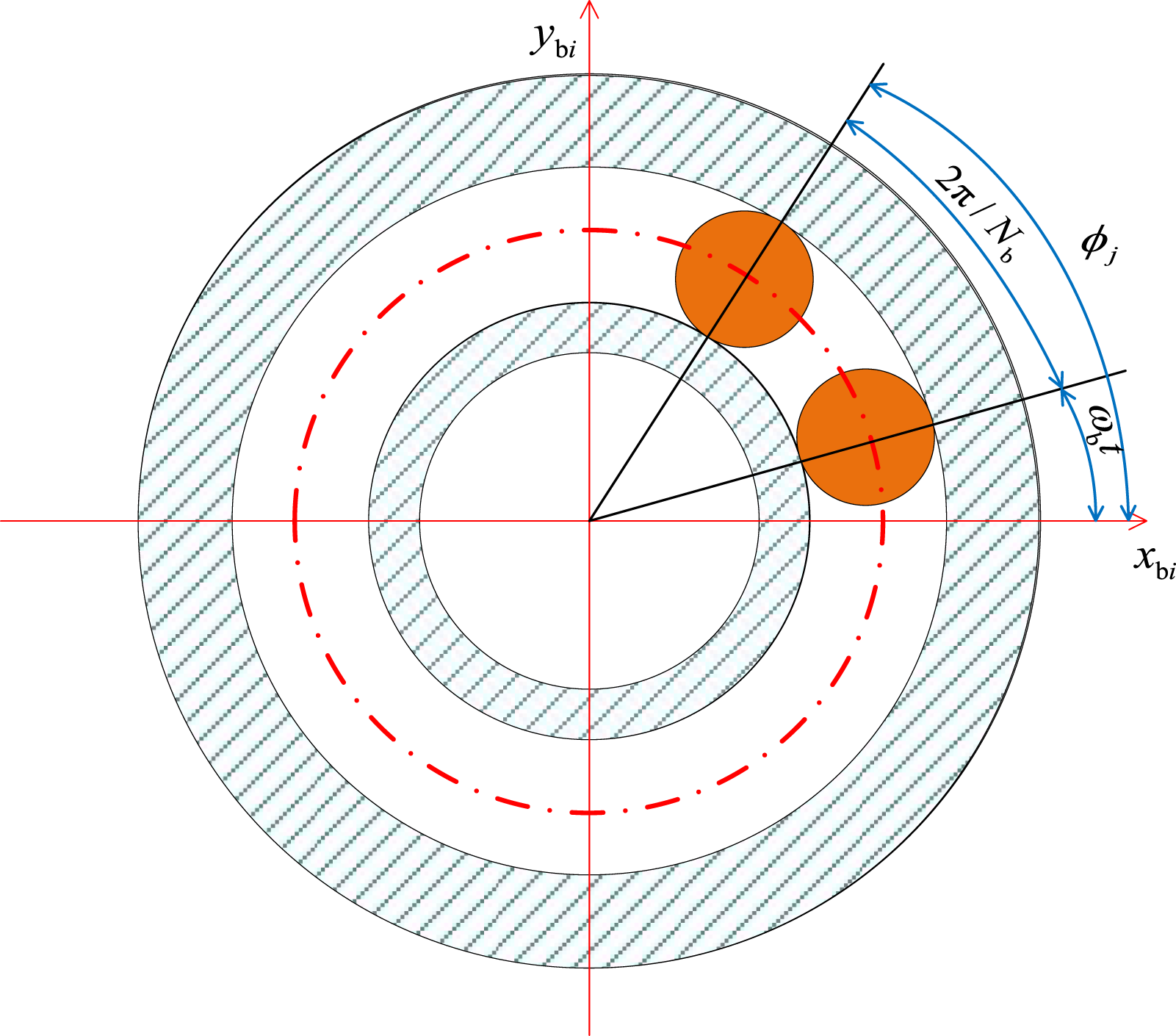


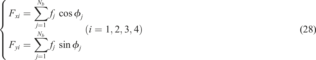
The dynamic bearing force is decomposed into component forces along the x, y directions. The two component forces are written as
Mathematical model of gear system
The vibration differential equation for the 16 degrees of freedom of the gear-bearing transmission system can be derived from the Lagrangian equation. The differential equation of the system is obtained by carrying equations (30)–(34) into the Lagrangian equation (29). The Lagrangian equation is as follows:

The displacement vector of the gear system is shown below:

The system takes into account the effects of friction, load, time-varying meshing stiffness, etc. The kinetic energy of the system T, the potential energy U due to the deformation of gears, drive shafts and bearings, and the dissipation energy R taking into account the damping effect of the components are all calculated. It can be described as


The generalized force vector is given below:

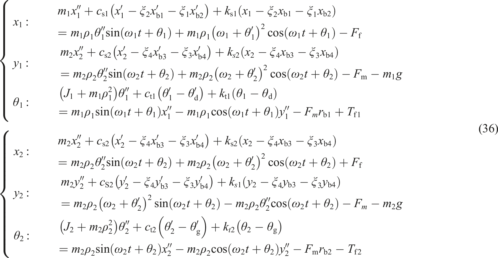
Differential equations of vibration at the input and output of the system are seen in below:
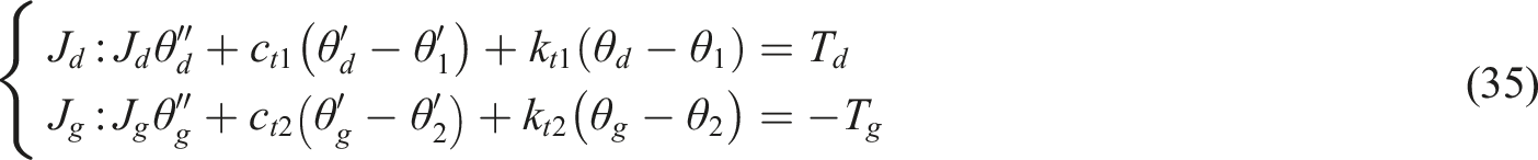
Differential equations for the vibration of the driving and driven gears are seen in below:
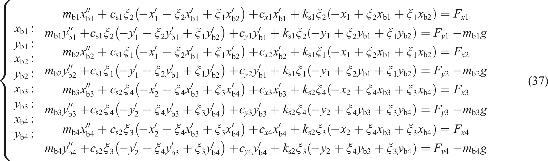
The differential equation of vibration of the bearing is as follows:
Result
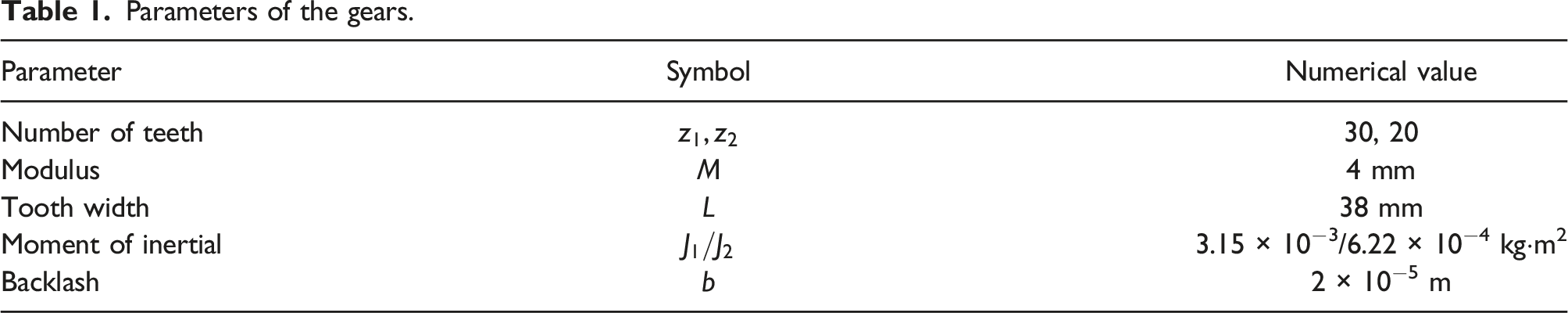
Parameters of the gears.
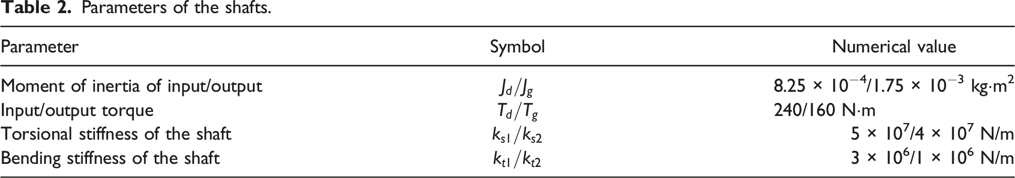
Parameters of the shafts.
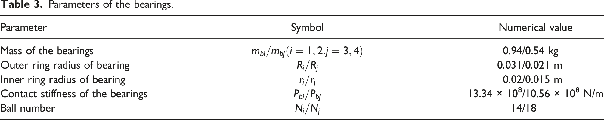
Parameters of the bearings.
Effect of profile shifted on vibration characteristics
In this section, on the basis of the time-varying meshing stiffness calculation of the above-mentioned profile shifted gears, the effect of different profile shifted coefficients on the vibration characteristics of the gear transmission system was investigated. The speed of the driving gear was set to 3000 r/min and the tooth surface friction coefficient is 0.1, the pinion shifting coefficient was selected as 0, 0.1, 0.15, −0.1, −0.15, and the other parameters were taken as the same values.
Figure 8 shows the time domain waveforms of the pinion with various profile shifted coefficients in the x2, y2, and θ2 directions. The profile shifted coefficient has varying degrees of influence on the gear’s vibration in different directions. The vibration displacement in the θ2 direction is significantly large. The vibration displacement in the x2 direction is most clearly affected by the profile shifted coefficient variation in Figure 8(a), as well as the vibration displacement decreasing when a negative profile shifted coefficient is employed and increasing when a positive profile shifted coefficient is used. The amplitude of the vibration displacement in the y2, θ2 directions does not change considerably in Figure 8(b) and (c), but the change in the θ2 direction is more obvious. Because the profile shifted coefficient has no effect on the gear system’s vibration waveform, the gear shifted has no effect on the gear system’s initial motion form. The time domain waveform at different profile shifted: (a) The displacement of x2 direction; (b) The displacement of y2 direction; (c) The displacement of θ2 direction.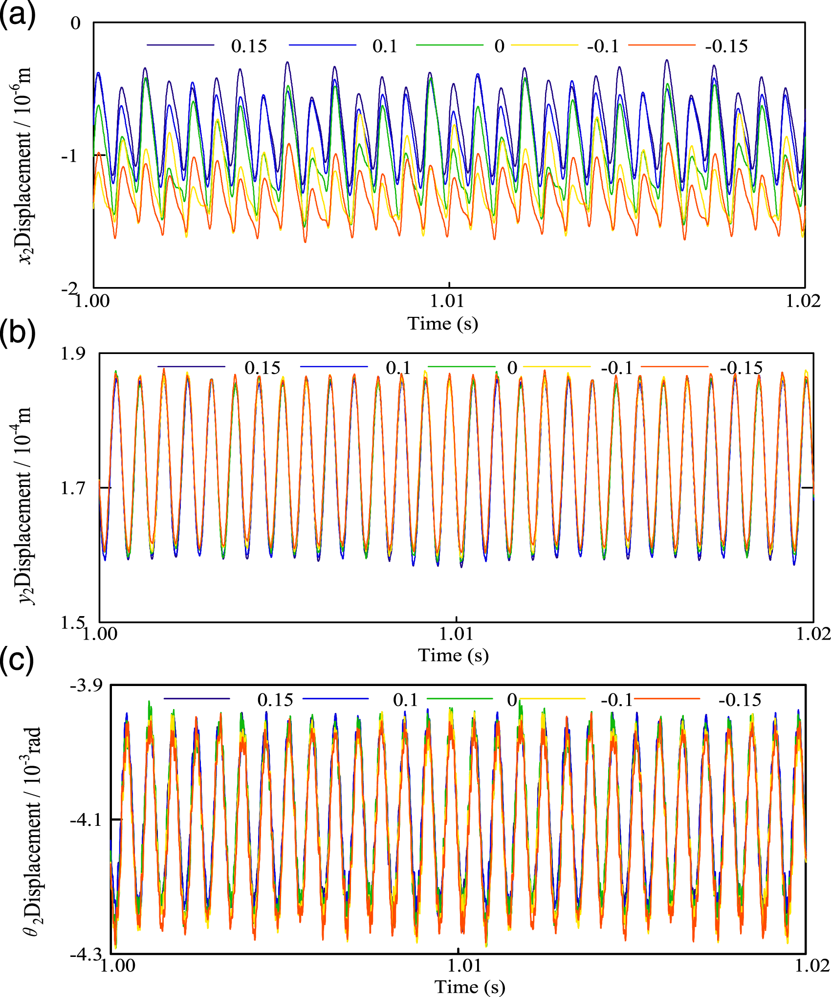
The peak-peak value (P-P) of the time domain waveform in the different directions is shown in Figure 9. It indicates the degree of changes in the vibration of the gear system. P-P has a tendency to decrease and then increase in the x2 and y2 direction. In the θ2 direction, it changes in alternating forms of increase and decrease. According to the changing trend of the P-P, the minimum value appears in the profile shifted coefficient −0.06,818. The vibration displacement of the gear system is minimal in this case. The peak-peak value of the time domain waveform: (a) In x2 direction; (b) In y2 direction; (c) In θ2 direction.
The spectrum plots of standard gearing in the x2, y2, and θ2 directions are shown in Figure 10(a)–(c). As shown in the figure the gears have approximately the same frequency components in all three directions, and the meshing frequency The frequency spectrum of the system at no profile shifted: (a) The spectrum of x2 direction; (b) The spectrum of y2 direction; (c) The spectrum of θ2 direction.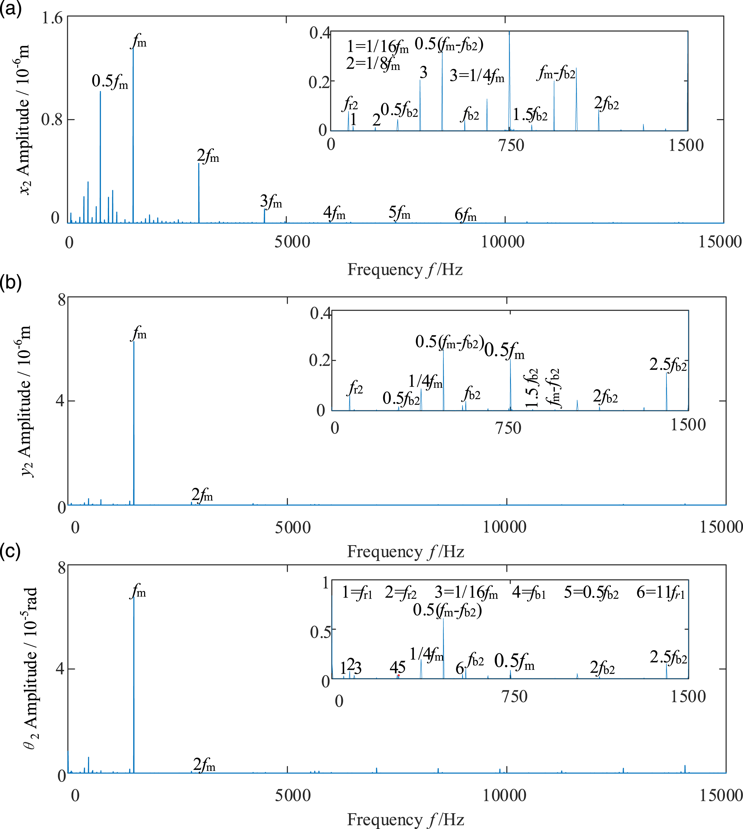
The effect of gear profile shifted on gear vibration in the y, θ direction is slight in the frequency spectrum, so this work only makes analysis for the variation in the x direction. Figure 11 shows the spectrum of the shifted gear in the x2 direction with different shifting coefficients, where (a) and (b) are negative transmission and (c) and (d) are positive transmission. Compared with Figure 10(a), the magnitudes at The frequency spectrum of the system at different profile shifted: (a) At profile shifted in −0.1; (b) At profile shifted in −0.15; (c) At profile shifted in 0.1; (d) At profile shifted in 0.15. The amplitude of the frequency.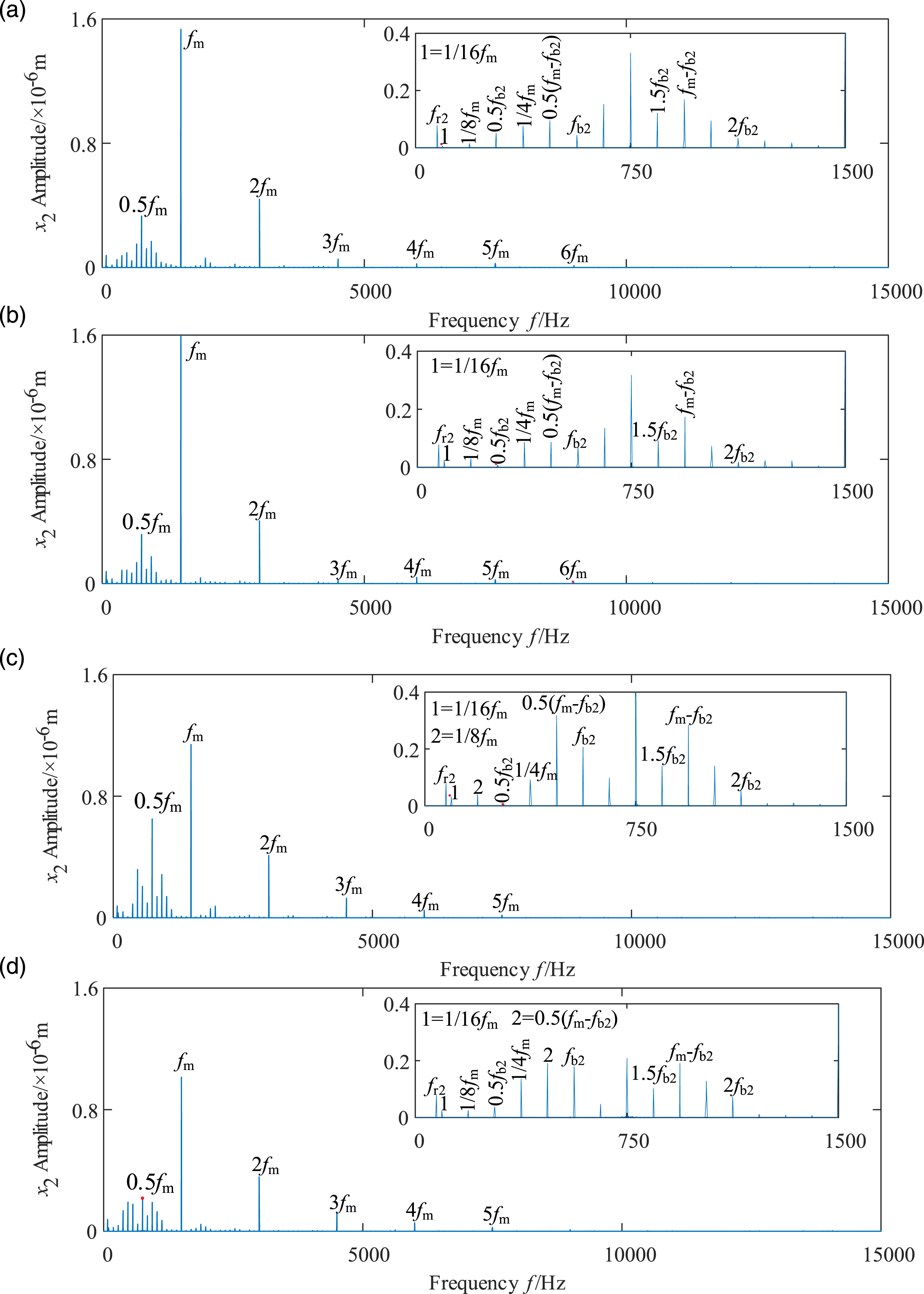
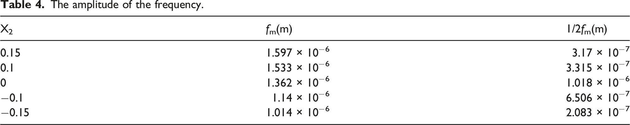
Figure 12 shows the dynamic meshing force of the gears with different profile shifted coefficients. As shown in the figure, the dynamic meshing force of the gearing system is maximum when the gear shifting coefficient Gear dynamic meshing force at different profile shifted: (a) Dynamic meshing force; (b) Regional enlarged drawing.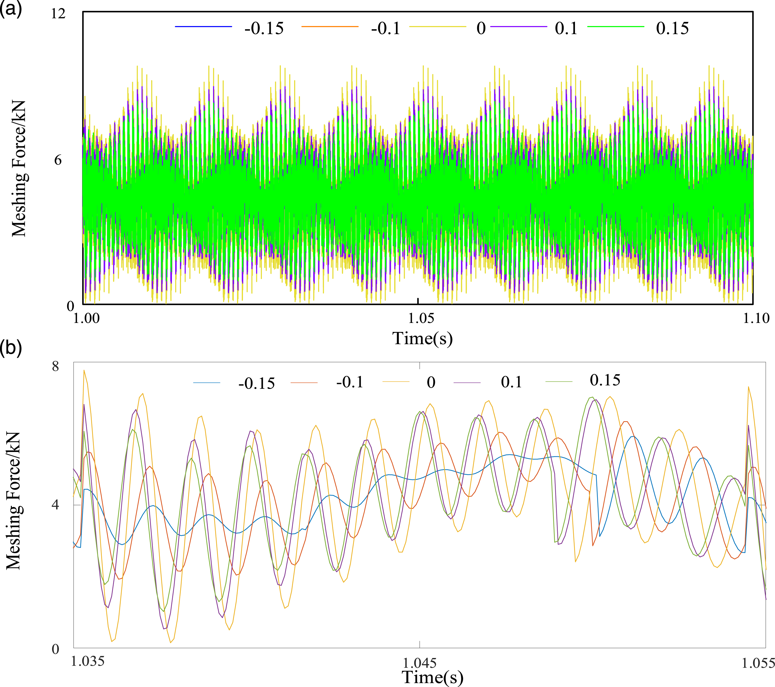
Effect of input torque on vibration characteristics
The effect of the input torque on the dynamic characteristics of the gear system is investigated in this work. Figure 13 shows the time domain waveform with input torque as the control parameter at profile shifted coefficient −0.06,818. It can be seen in Figure 13 that the gear system’s vibration will be deflected as the input torque change. Meanwhile, the vibration displacement of the gear system increases as the input torque increases. The time domain waveform at different torque: (a) The displacement of x2 direction; (b) The displacement of y2 direction; (c) The displacement of θ2 direction.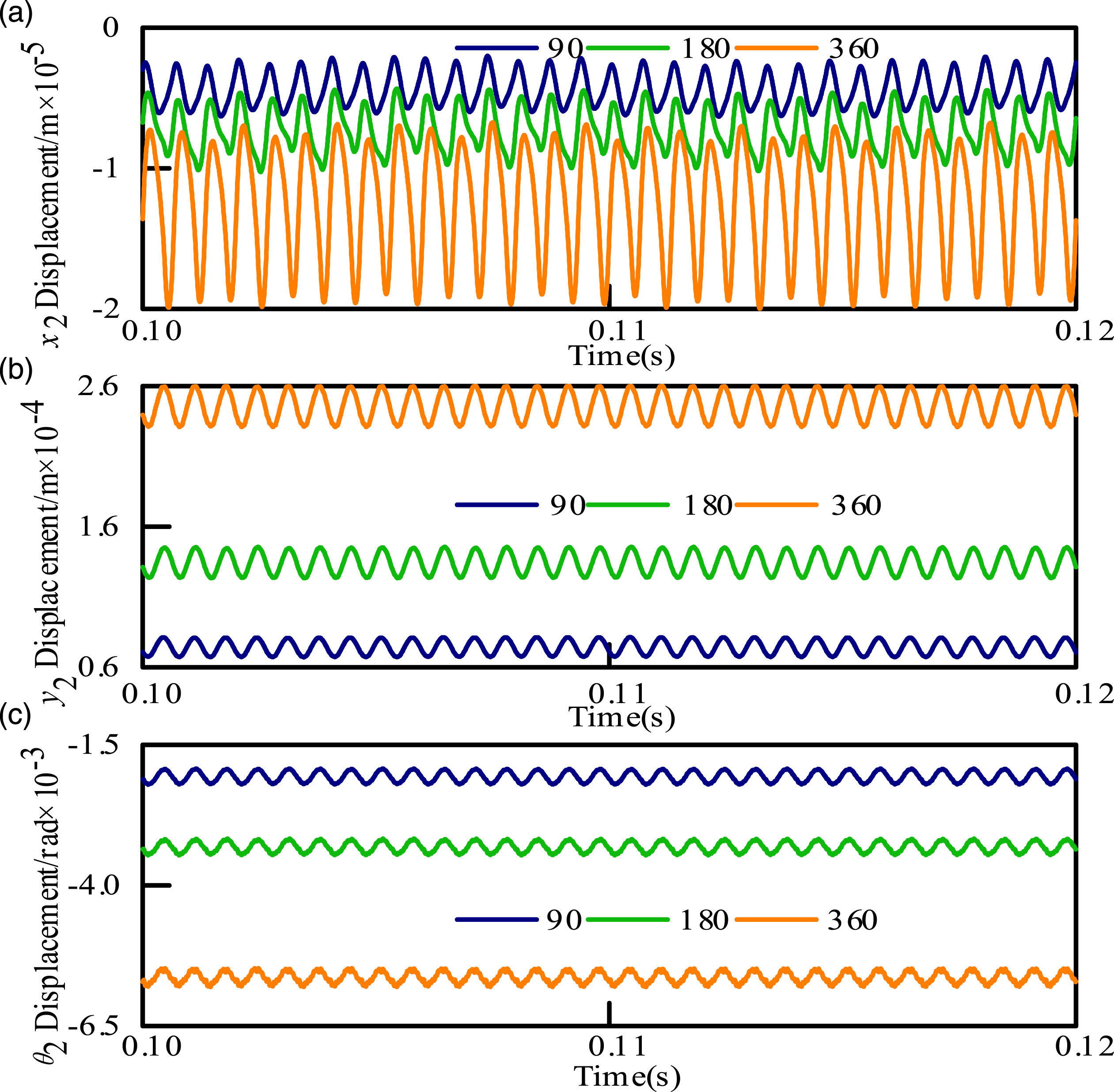
The frequency spectra of the gear system under different input torques in x2, y2, and θ2 directions are shown in Figure 14. It is obviously that the meshing frequency fm is the dominant frequency and its amplitude much larger than other frequency components. The multiples of the meshing frequency 2fm can be seen in the figure. In the x2 and y2 directions, the amplitude of meshing frequency tends to increase with a change in the input torque. It is worth noting that there is a significant increase in 0.5fm in Figure 14(b). There is an apparent change of frequency amplitude 0.5 (fm − fb2) in the θ2 direction. The frequency spectrum of the system under different input torques: (a) Td = 90 N·m; (b) Td = 180 N·m; (c) Td = 360 N·m.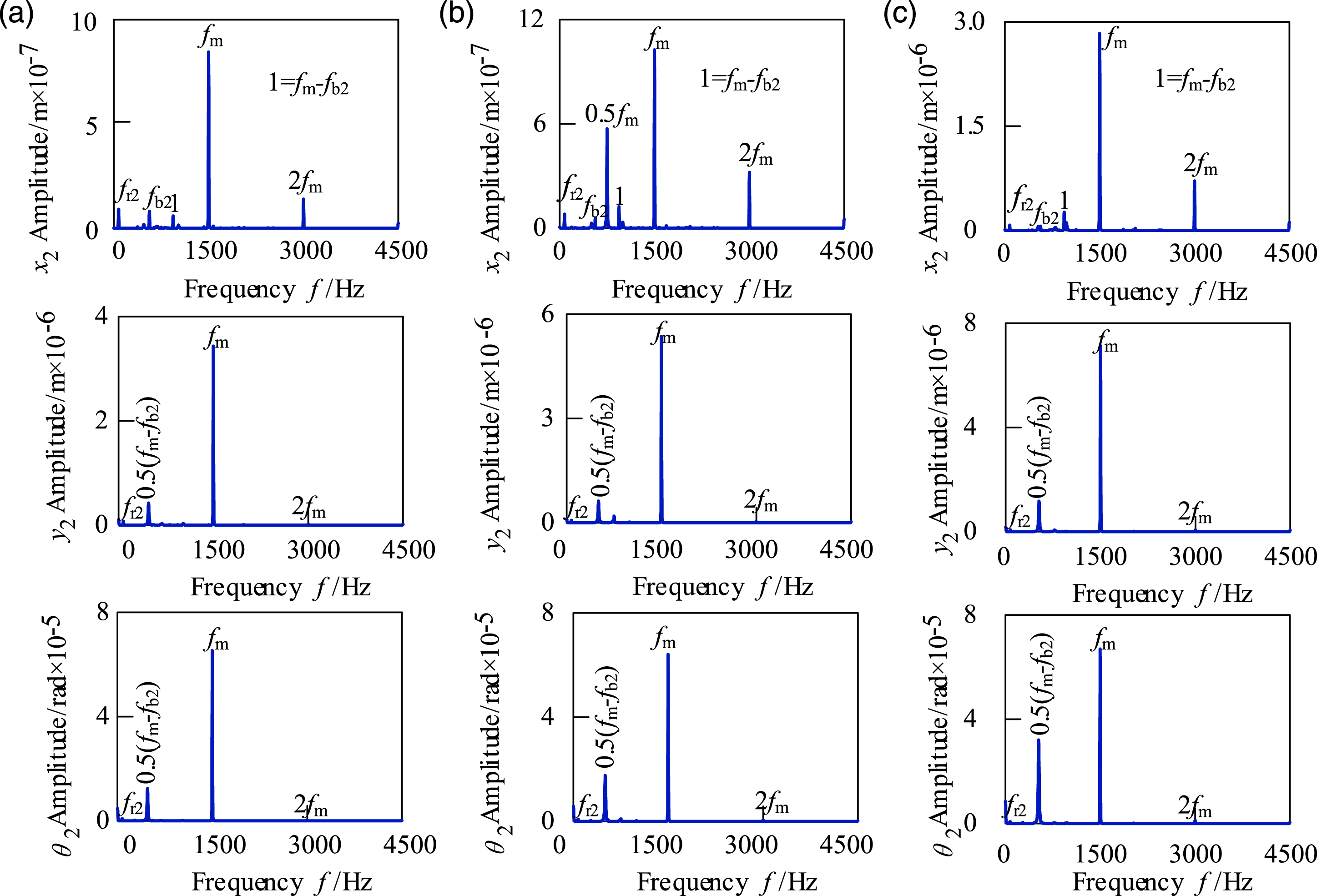
Conclusions
In this paper, a dynamic model of a 16-degree-of-freedom bending-torsional coupling profile shifted gear transmission system is established to study the influence of the profile shifted coefficient on the system. The potential energy method is used to derive and solve the time-varying mesh stiffness of the profile shifted gear. The vibration characteristics of the profile shifted gear transmission system are studied through the time domain and frequency domain diagrams. The main conclusions drawn from this study are as follows: 1. Considering the Hertzian contact stiffness, bending stiffness, shear stiffness and axial compression stiffness, the pinion is shifted, and the time-varying meshing stiffness of the profile shifted gear is solved by numerical simulation. For positive transmission, the time-varying meshing stiffness of the gears increases and the double-tooth meshing interval decreases. On the contrary, for negative transmission, the time-varying mesh stiffness of the gears decreases, but the double-tooth meshing interval increases. 2. Through the analysis of the time domain diagram, the vibration displacement undergoes a complex variation process as the profile shifted coefficient changes, moreover, the vibration displacement can be effectively reduced when a suitable coefficient is used. Meanwhile, when the positive transmission is adopted, the meshing frequency component increases and the vibration shock advances; when the negative transmission is adopted, the meshing frequency component decreases and the vibration shock lags. 3. With the increase of the input torque, the vibration displacement will be intensified and deflected, and the amplitude of frequency has an obvious change.
In all, the model established in this paper provides assistance in the investigation of the vibration of the profile shifted gear system. Conclusions can be used for applications on gear vibration and noise reduction.
Footnotes
Declaration of conflicting interests
The author(s) declared no potential conflicts of interest with respect to the research, authorship, and/or publication of this article.
Funding
The author(s) disclosed receipt of the following financial support for the research, authorship, and/or publication of this article: The project was supported by the Liaoning Revitalization Talents Program (no. XLYC1905003) and Educational Commission of Liaoning Province of China (no. LQGD2020016).