
Abstract
This paper proposes a frequency domain-based analytical framework for seismic performance of viscously damped outrigger systems. Based on a core–outrigger–damper–column simplified model, the global dynamic stiffness matrix is assembled from the core modeled as a Timoshenko beam, damped outriggers as complex rotational stiffness comprising outriggers, dampers, and perimeter columns, and inherent damping using Leung’s theory and modal damping construction. A general numerical method combining Wittrick-Williams algorithm and Newtonian iteration is developed to study the dynamic characteristic of such systems with multiple damped outriggers. The fast Fourier transformation (FFT) and the inverse Fourier transformation (IFFT) are then integrated with the principle of potential energy to obtain the equivalent nodal force and thus the time history response by transformations between time and frequency domains. Finally, the stochastic analysis is conducted via the transfer function resulting from the global stiffness matrix with the stochastic seismic excitation following Kanai-Tajimi spectrum. The proposed approach is verified by comparison with the finite element method through a case study of a tall building implemented with viscously damped outriggers. This study shows that the proposed analytical framework could serve as a powerful tool for evaluating the performance of viscously damped outrigger systems.
Highlight
A frequency domain-based analytical framework is proposed for the seismic performance evaluation of dampedoutrigger systems. Wittrick-Williams algorithm and Newtonian iteration are combined to study dynamic characteristic. FFT and IFFT are integrated with the principle of potential energy to obtain time history dynamic response. Stochastic seismic excitation is adopted following Kanai-Tajimi spectrum. A complete set of non-dimensional parameters are defined associated with the structural properties and dampers. The core is modeled as a Timoshenko beam to better represent the mechanism of damped outriggers.
Introduction
In the past several decades, the number of high-rise buildings has skyrocketed to address the housing issue due to the rapid growth of global population and process of urbanization. 1 As tall buildings continued soaring toward sky, outriggers were introduced to connect core and perimeter columns as a whole to resist lateral excitations, for example, wind and earthquake. 2 A great deal of research studies regarding the number, location, and stiffness of outriggers has been carried out.3–7 These studies emphasized the benefit of outriggers from the structural stiffness perspective.
However, the increase of structural stiffness typically means the increase of sizes of structural members, which in turn leads to stronger seismic excitation and thus requires bigger sizes of structural members and so on and so forth. One solution to break this dilemma is to supplement damping by installing energy dissipation devices in tall buildings, which has been vastly studied.8,9 For instance, active tuned mass dampers, 10 tuned liquid sloshing dampers, 11 and magnetorheological (MR) dampers 12 have been applied to reduce wind-induced vibration in a benchmark tall building. Nevertheless, the typical arrangements of dampers in tall buildings are either ineffective because of the relatively small inter-story drift or too costly due to the mass and space requirement for a big unit on the top of the buildings. 13 A more effective arrangement of dampers is in need.
To tackle the aforementioned issues, O’Neill 14 and Smith and Willford 13 presented the damped outrigger concept where viscous dampers were vertically installed on the load path between the perimeter columns and the end of outriggers cantilevered from the core. In comparison to traditional outriggers which strengthen the connection of core and outer columns as a whole, the damped outrigger systems focus on the supplementary damping aspect at the expense of structural stiffness; the gain of increasing damping to reduce excessive vibration outweighs the reduction of stiffness. Later, this concept was applied in two resident buildings in the Philippines, and the supplemental damping ratio and construction cost were around 5.2–11.2% and $5 million USD, respectively. 15
Inspired by this innovation, a good number of research studies regarding theoretical analysis, finite element method (FEM), and experimental validation have been conducted. Theoretically, Chen and Wang 16 and Chen et al. 17 studied the relationship of damping and damper based on a core–outrigger–damper model using virtual work principle and Dirac function, respectively. Tan et al. 18 and Fang et al. 19 pointed out that perimeter columns should be included. Subsequently, the damped outrigger concept has been developed to include buckling-restrained braces (BRBs),20,21 variable stiffness dampers, 22 MR,23,24 tuned inertial mass electromagnetic transduce, and 25 rotational inertial dampers. 26 An inspiring development was the negative stiffness damper, which could potentially remove the restriction of perimeter columns and expand the application scope of damped outrigger system. 27 These studies mainly focused on theoretical analysis and used the Euler–Bernoulli beam theory to model the core.
The FEM analysis was used to verify the effectiveness of the core–outrigger–damper–column representation. For instance, such representation was verified by comparing the dynamic characteristic, inter-story drift, and roof acceleration with the corresponding 3D finite element model. 28 A more elaborated case study can be found in Lu et al. 29 Subsequently, the 3D finite element analysis of such system equipped with viscous dampers or/and BRB were examined in Refs. 30–32. These studies further paved the way for applying damped outriggers in engineering practice.
A series of experiments were carried out to validate the vibration reduction of damped outrigger systems. A shaking table test was conducted to test the seismic performance of an eight-story steel structure with two outriggers.33,34 A structure implemented with variable stiffness dampers was conducted under harmonic excitation, 22 while real-time hybrid simulation of an MR-equipped damped outrigger system was conducted with MR tested experimentally and the rest modeled numerically. 35 Similarly, the real-time hybrid simulation of a viscously damped outrigger system subject to wind and earthquake excitation was carried out.36,37 These studies verified the effectiveness of damped outrigger system in reducing structural responses under lateral loadings.
Thus far, applications of damped outrigger systems have been found in two resident buildings of 40-story Shangri-La Palace in the Philippines, 13 a 68-story North-East Asia Trade Tower in Songdo in Korea, 38 and an office tower in New York City. 39 Other excellent reviews on structural outrigger systems and their implementations can also be found in Smith, 40 Ho, 41 and Kavyashree et al. 42
Despite the encouraging research progress so far, there still lacks a comprehensive method for evaluating the seismic performance of viscously damped outrigger systems while addressing the following four issues. First, the previous studies modeled the core as an Euler–Bernoulli beam, which is acceptable where outrigger systems typically could be applied with the bending deformation of the core to be dominant. Because the energy dissipation mechanism of the damped outrigger systems is to make use of vertical deformation between the core and perimeter columns and to fully assess the applicability of damped outrigger systems, Timoshenko beam theory is required to capture the influence of shear deformation and rotatory inertia of the core, or more compactly as the slenderness ratio of height–radius of the core. Second, although there have been some valuable insights of such systems by using FEM and based on a specific building carrying out parametric analysis, the conclusions obtained have limited extension to cover wider ranges of buildings. This is because the parameterization is not complete and only includes some of the non-dimensional parameters defined in this paper: slenderness ratio of height–radius of the core, stiffness ratios of core–column and core–outrigger, number and location of outriggers, and damper parameters. Third, as the essence of the damped outrigger system is to increase supplementary damping at the expense of structural stiffness, that is, the gain obtained from the supplementary damping has to outweigh the loss of structural stiffness, such tradeoff between supplementary damping and structural stiffness reflected in the design practice is to evaluate time history dynamic response of the systems under seismic excitation, which could provide intuitive perception for engineers and researchers. Finally, because structural responses of the systems vary even with the same peak ground acceleration due to the frequency content and duration of earthquakes, that is, the stochasticity of seismic excitation in nature, a more scientific way to examine the system performance is to take such stochasticity into account during analysis. A systematic approach that addresses the aforementioned aspects needs to be developed.
Because of the capacity of large output force and reliable performance during their lifetime, viscous dampers have been playing an important role in mitigating seismic responses.9,43,44 In this paper, a frequency domain-based analytical framework for seismic performance of viscously damped outrigger systems is proposed. Based on a core–outrigger–damper–column simplified model, the global dynamic stiffness matrix is assembled from the core modeled as a Timoshenko beam, damped outriggers as complex rotational stiffness comprising outriggers, dampers, and perimeter columns, and inherent damping using Leung’s theory 45 and modal damping construction. A general numerical method combing Wittrick-Williams algorithm46,47 and Newtonian iteration 48 is developed to study the dynamic characteristic of such systems with multiple damped outriggers. The fast Fourier transformation (FFT) and inverse fast Fourier transformation (IFFT) are then integrated with the principle of potential energy to obtain the equivalent nodal force and thus the time history response by transformations between time and frequency domains. Finally, the stochastic analysis is conducted via the transfer function resulting from the global stiffness matrix with the stochastic seismic excitation following Kanai-Tajimi spectrum. The proposed approach is verified by comparison with the finite element method through a case study of a tall building implemented with viscously damped outriggers.
The proposed analytical framework
This section lays out the proposed analytical framework for seismic performance viscously damped outrigger systems, shown in Figure 1. This analytical framework contains three main components: modeling, analytical formulation, and numerical solutions, involving dynamic characteristic, deterministic, and stochastic analyses, which will be elaborated in the following sections. Frequency domain-based analytical framework for seismic performance of viscously damped outrigger systems.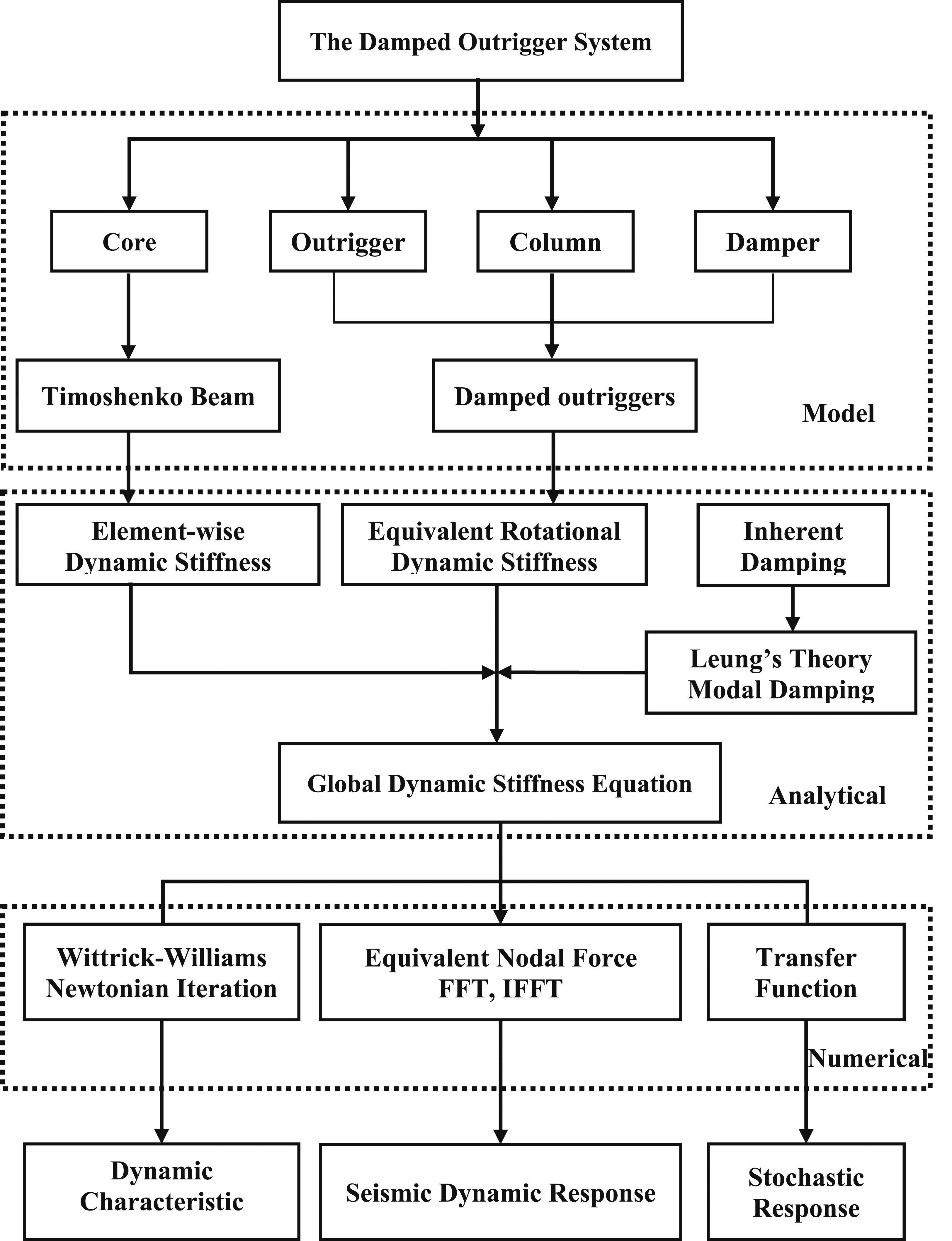
Modeling
Before going into detailed analysis using the finite element method for engineering application, abstracting key components that form the main mechanism and looking into the insight of the whole structural behavior are obviously beneficial. This was done in the benchmark study of a 76-story building, where the building was modeled as a cantilevered beam and structural response could then be derived from the analysis of the beam. Likewise for traditional outrigger systems, Taranath simplified the structure as a core–outrigger–column model while neglecting the typical floors and beams. 3
In Figure 1, the proposed analytical framework contains two levels of modeling: the higher level represents the damped outrigger systems as a core–outrigger–damper–column model, whereas the lower level uses Timoshenko beam to model the core, and damped outriggers to comprehensively model the remaining three, later modeled as equivalent rotational dynamic stiffness. Obviously, the core–outrigger–damper–column model for damped outrigger systems is a natural extension of classic outrigger model with dampers included. Notice the similarity of the resisting moments in both traditional and damped outrigger systems: the resisting moments due to the compression and tension of perimeter columns act on the core through outriggers; consequently, the damped outrigger systems can also be further simplified as a cantilevered beam with equivalent rotational dynamic stiffness attached with it. As opposed to traditional outriggers which only provide stiffness contribution, the equivalent rotational dynamic stiffness has contribution both in stiffness and damping because of the presence of dampers, and the coupling effect of outriggers due to compatibility at perimeter columns further makes the analysis of such systems complicated. Beside the relatively big stiffness compared to installed dampers, this is probably why the perimeter columns were neglected in the early research studies, where the axial stiffness of perimeter columns was assumed to be infinitely large, at which point the coupling effect between different outriggers disappeared. The core–outrigger–damper–column model for damped outrigger systems was presented in the author’s early works18,19 and have been verified by other researchers.27,49,50
In regarding the core, a Timoshenko beam is suggested in the proposed analytical framework. The early theorical work always used Euler–Bernoulli beam to model the core with the underlying assumption that the bending deformation of the core is dominant, which is partly true when outriggers are applied for tall buildings. However, the presence of shear deformation and rotatory inertia of tall buildings, as well as buildings with the implementation of multiple damped outriggers, could significantly influence the modal damping ratios of damped outrigger systems, which was addressed in a recent paper. 51 For this reason and as well as an Euler–Bernoulli beam could be considered as a special case of a Timoshenko beam, the Timoshenko beam theory is adopted in the analytical framework for its capability of applying into more tall buildings.
Analytical method
Although the finite element method that discretizes the target structure into small segments and uses piece-wise linear function to approximate exact solution has been overwhelmingly successful in engineering practice with increasing computational power, the analysis results tend to be project specific, that is, the conclusions are only applicable for the analyzed building.
In contrast to the finite element method, as shown in Figure 1, dynamic stiffness method is adopted herein. The global dynamic stiffness matrix of the damped outrigger system results from element-wise dynamic stiffness of the core split by outriggers, and equivalent rotational dynamic stiffness of damped outriggers composed of outriggers, dampers and perimeter columns, and intrinsic damping. By introducing some non-dimensional parameters that characterize the structural properties into the formulation of dynamic stiffness matrix, the analysis results are no longer limited to a specific building but rather wider range of buildings that feature the same properties.
As with distributed-parameter method, the dynamic stiffness method derives its solution from exact partial differential equations of motion, but it takes one step further by relating its end forces to its end deformation. While applying boundary and compatibility conditions to solve the equations in the former seems tedious, these conditions are automatically satisfied in the process of assembling the dynamic stiffness matrix which is analogous to the finite element method. Furthermore, such treatment turns out to be consistent with the derivation of equivalent rotational dynamic stiffness of damped outriggers.
The previous theoretical analysis in this field ignored intrinsic damping of the system, which is acceptable from the perspective of supplementary damping ratio. But for dynamic response evaluation, the absence of intrinsic damping could overestimate the suppression effect of the damped outrigger systems. To appropriately evaluate the superiority of damped outrigger systems over the corresponding traditional outrigger systems, the inherent damping matrix is included in the analytical framework, specifically, Leung’s theory is used to derive frequency-dependent mass matrix from dynamic stiffness matrix and the inherent damping matrix is constructed using the modal damping theory for specified intrinsic modal damping ratios, which will be elaborated in the next section.
Analysis types and numerical methods
In Figure 1, the analytical framework provides a useful tool to systematically evaluate the performance of viscously damped outrigger systems and develops corresponding numerical solutions to study systems’ dynamic characteristic, seismic dynamic response, and stochastic response considering the uncertain of earthquake excitation. The Wittrick-Williams (WW) algorithm is integrated with Newtonian iteration to study the dynamic characteristic. For tall buildings with multiple damped outriggers, obtaining characteristic equation of such systems is practically unfeasible. This is when numerical methods come into play. Specifically, the natural frequencies of the corresponding traditional outrigger system calculated by the WW algorithm are used as initial values for Newtonian iteration due to its local convergence property, and the modal damping ratios and natural frequencies are then extracted from the obtained complex frequencies of the system. FFT and IFFT are combined with the principle of potential energy to analyze seismic dynamic response. Notice that the similarity of dynamic stiffness method and finite element method, the seismic excitation is first transformed into frequency domain via FFT, the equivalent nodal force is then calculated based on the principle of potential energy, and the frequency-dependent response of the system is subsequently calculated and transformed back in time domain via inverse fast Fourier transformation (IFFT) to obtain the time history response. The dynamic stiffness method is blended with the random vibration theory to conduct stochastic analysis. With stochastic seismic excitation modeled as Kanai-Tajimi spectrum, the dynamic stiffness equation of such system is reformulated in the form of transfer function of the nodal deformation to seismic excitation. Subsequently, other physical response quantities as well as their associated response power spectrums can be calculated. Because only a few degrees of freedom exist in the formulation of dynamic stiffness matrix, the response variance can be calculated with a little computation expensive.
Problem formulation
This section starts with the core–outrigger–damper–column model of the viscously damped outrigger system. The derivations of element-wise dynamic stiffness of the core split by outriggers and equivalent rotational dynamic stiffness composed of outriggers, dampers, and perimeter columns are briefly revisited for the sake of completeness, more details are referred to Fang. 51 Following Leung’s theory and the modal damping theory, the inherent damping matrix is constructed, and the dynamic stiffness equation of the viscously damped outrigger system is finally derived.
The core–outrigger–damper–column model
Because the core, outriggers, dampers, and columns form the main mechanism of the damped outrigger system, the core–outrigger–damper–column model is adopted herein. As shown in Figure 2(a), the core having a height of Core–outrigger–damper column model of the damped outrigger system. (a) The analytical model. (b) The simplified model.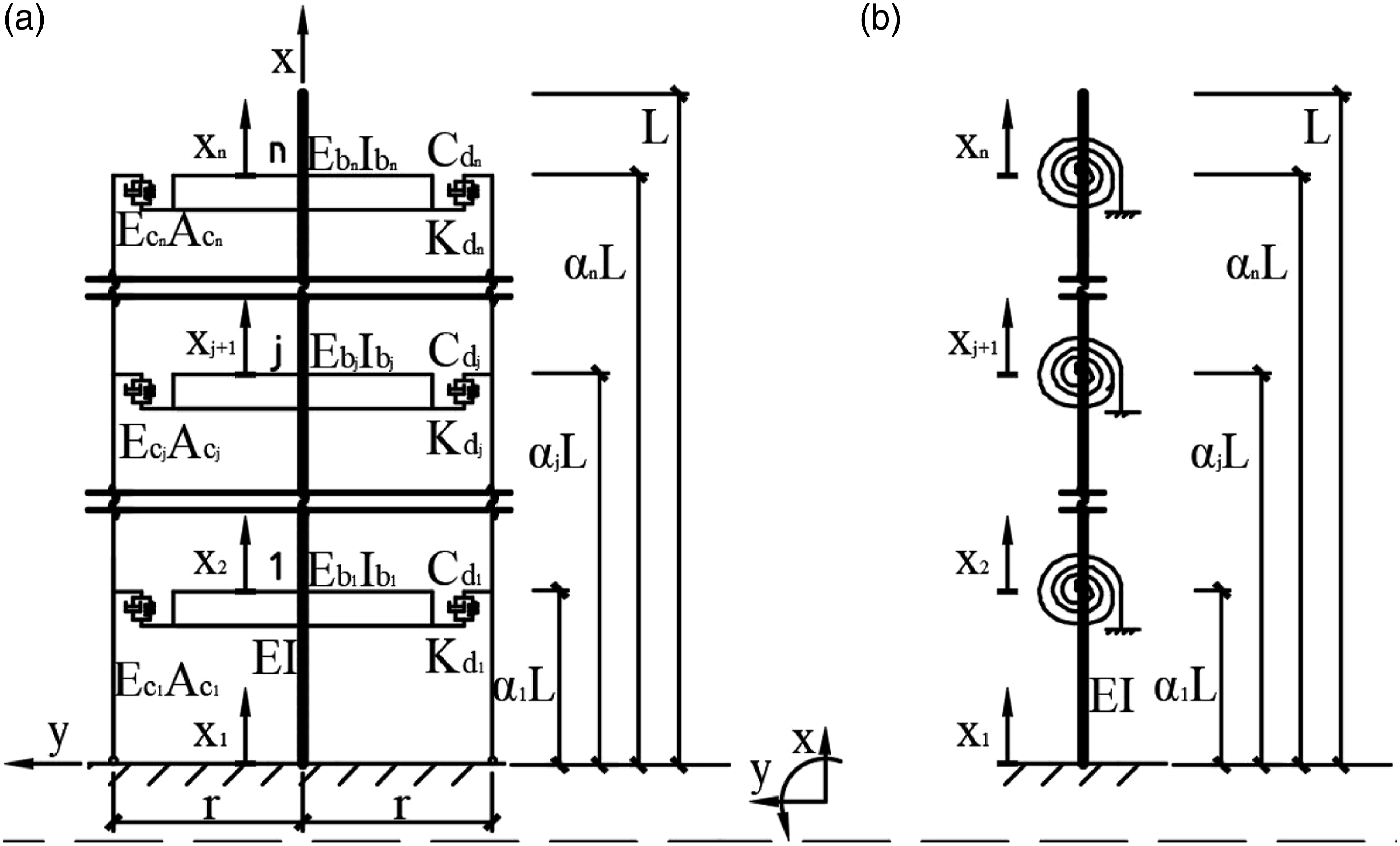
The element-wise dynamic stiffness
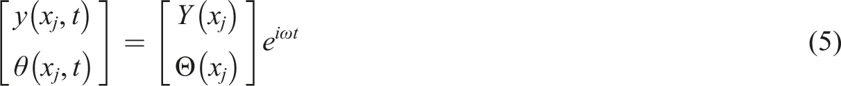
For each element segmented by outriggers and modeled as a uniform Timoshenko beam, the equations of free vibration are given as follows
53


Three non-dimensional parameters relating to excitation frequency, shear deformation, and rotatory deformation are introduced


The slenderness ratio of height–radius of the core is defined as follows

The shear deformation and rotatory inertia can then be rewritten as follows

Note that
In order to derive the non-dimensional dynamic stiffness matrix, axial position and element length are normalized by

For a Timoshenko beam, the shear force and moment, respectively, are as follows
52


The shear forces and moments at both ends are defined as follows

By relating end forces to end deformation with equations (5)–(9), the non-dimensional element-wise dynamic stiffness of a Timoshenko beam can be expressed as follows

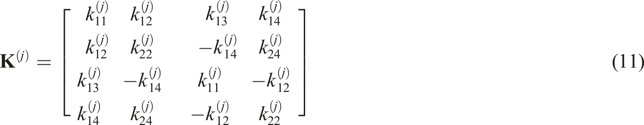
The entries of the dynamic stiffness matrix,
Equivalent rotational dynamic stiffness
Derivation of structures with one viscously damped outrigger systems is rather simple because the viscous damper is connected in series with the perimeter column, which resembles Maxwell model with a spring and a viscous damper in series. 54 In the case of structures with more damped outriggers, things get complicated due to the coupling effect of outriggers along the perimeter column direction. Instead of deriving the equivalent rotational dynamic stiffness from the stiffness perspective, the dynamic flexibility matrix was used based on deformation compatibility, as was done in Tan et al. 55 and Fang, Tan. 19 In the recent paper, 51 the author extended previous work by considering the variation of size of columns and outriggers at different elevation levels. For the sake of completeness, the derivation is briefly reviewed herein.
Due to the deformation compatibility of outriggers along the perimeter column direction, the rotation of the core at the j-th outrigger level is induced by the cumulative deformation of the perimeter column from the ground, the corresponding damper deformation, and the rotation of the j-th outrigger, that is,


The deformation of the perimeter column between the j-th and j-1-th outriggers is as follows

The force equilibrium equation at each outrigger level yields the following

Four non-dimensional parameters associated with structural properties and damper parameters, for example, stiffness ratio of core–column, stiffness ratio of core–outrigger, viscous damping coefficient, and stiffness of viscous dampers, are further defined as follows


Substituting equations (13)–(19) into equation (12) and having some algebraic manipulations lead to


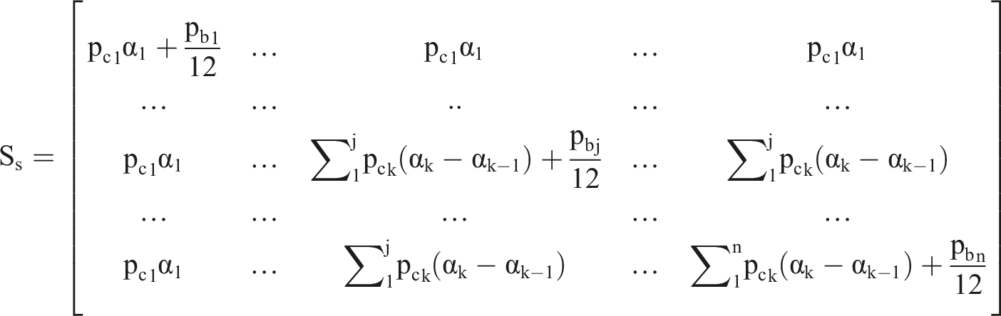
Equation (19) can be rewritten as dynamic stiffness form


It is worth mentioning that the structural component,
Inherent damping matrix construction
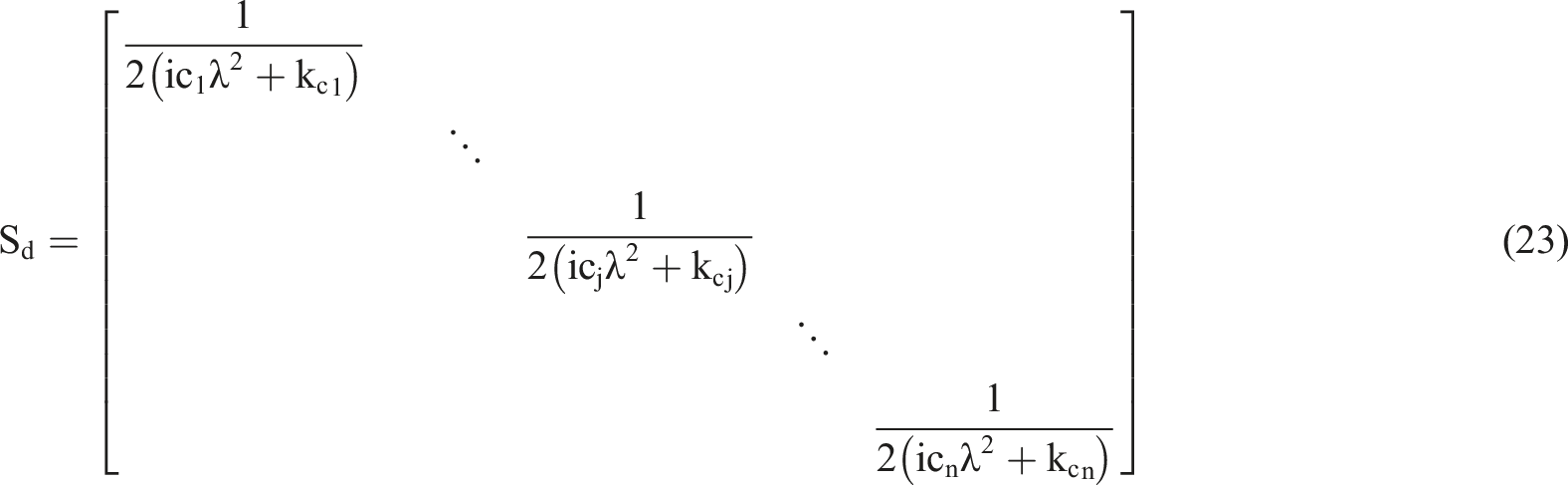
Although a damping term could be included in partial differential equation to derive element-wise dynamic stiffness, it is challenging to find the correspondence in the finite element method. Alternately, this section constructs frequency-dependent damping matrix combing Leung’s theory and the modal damping theory.
Probably, the simplest way to construct damping matrix is to use modal damping construction, which is a linear combination of mass and stiffness matrixes. In order to find the corresponding matrixes analogous to the finite element method, according to Leung’s theory that relates the mass matrix to the dynamic stiffness matrix
45

To improve the calculation efficiency in differential, the difference formula is used

Similar to the classical modal analysis, applying the orthogonal conditions by manipulating the shape function leads to


As most used in structural dynamic computation, modal damping is assumed, which also satisfies orthogonality

The inherent damping matrix following the above derivation can then be given as follows

Therefore, the modified dynamic stiffness matrix including inherent damping is as follows

Dynamic stiffness equation
Analogous to the finite element method, the dynamic stiffness equation is formulated by assembling element-wise dynamic stiffness of the core (equation (10), equivalent rotational dynamic stiffness of damped outriggers composed of outriggers, dampers, and perimeter columns (equation (24)), and inherent damping matrix (equation (32)), that is,


It is worth noting that the element-wise dynamic stiffness
Numerical solutions for performance evaluation
The previous section formulated the viscously damped outrigger system using the dynamic stiffness method, and this section develops three numerical solutions to evaluate the system performance with respect to dynamic characteristic, seismic dynamic response, and stochastic response.
Dynamic characteristic via Wittrick-Williams algorithm and Newtonian iteration
To study the dynamic characteristic of viscously damped outrigger systems, the free vibration of the transcendental equation


Because using the determinant of dynamic stiffness matrix for multiple damped outrigger systems to derive analytical formula of structural dynamic characteristic is practically infeasible, a numerical method needs to be developed. In the recent paper, a universal numerical solution to solve such systems is presented via combination of the Wittrick-Williams (WW) algorithm and Newtonian iteration; specifically, the Newtonian iteration due to its local convergence property starts with the natural frequencies of the corresponding undamped outrigger system, which are calculated by the WW algorithms. 51
Essentially, the WW algorithm is a frequency calculator by calculating the total number of natural frequencies below the trial frequency

The algorithm calculates the natural frequencies by continuously narrowing down frequency interval,

Once the frequencies

Seismic dynamic response by the means of FFT and IFFT
Besides dynamic characteristic, dynamic response of such systems subject to earthquake excitation is also of concern, as is common practice in engineering application. This subsection presents a method to calculate the seismic dynamic response of viscously damped outrigger systems by means of FFT, the principle of potential energy, and inverse fast Fourier transformation (IFFT).
Frist, notice that the global dynamic stiffness of the damped outrigger system is formulated in frequency domain and the seismic input is transformed into the frequency domain via FFT

Second, as the formulation of dynamic stiffness is the relationship of end forces versus end deformation similarly to the finite element method, distributed forces need to be converted into the form of nodal forces, and the equivalent nodal force can be derived from the principle of the total potential energy as follows
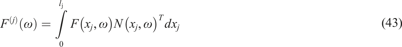
Assembling the element-wise equivalent nodal force vector leads to the global nodal force vector (equation (34)).
Finally, in view of equation (35), the time-domain structural response can be generated using the IFFT, for example, the nodal deformation is given by

Both the calculation of FFT and IFFT are available in MATLAB Toolbox.
Stochastic analysis
The previous focus was on deterministic analysis of viscously damped outrigger systems, but stochastic analysis is more essential due to two main kinds of uncertainties: (1) Structural parameters, such as material and geometrical deviations from the design and (2) external excitations like earthquake and wind. For the former, Monte Carlo simulation (MCS), 59 perturbation technique, 60 and polynomial chaos expansion 61 could be applied, whereas MCS, 59 perturbation technique, 62 stochastic averaging, 63 stochastic linearization,64–66 and equivalent nonlinear system 67 could be used in the latter situation. The challenge is the coupling between nonlinearity and stochasticity, which could be universally handled by MCS with various spectral representation methods to produce sample function involved more efficiently,68,69 or by probability density devolution method with the principle of preservation of probability. 70
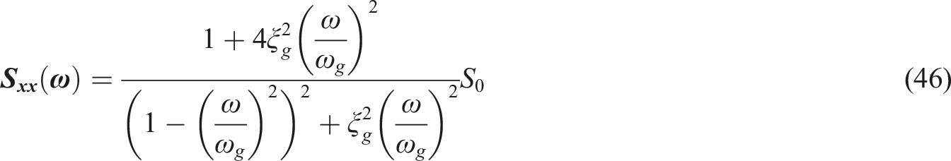
As external excitations are generally of more concern, particularly to deal with the uncertainty of earthquakes, Housner 71 proposed a white noise process to model earthquake-induced ground accelerations, followed by better spectrums characterized by filtered white noise models, for example, the Kanai-Tajimi spectrum72,73 and Clough-Penzien model. 74 Given that the Kanai-Tajimi spectrum is widely accepted, this model is integrated within the frequency domain-based analytical framework for the response variances of the viscously damped outrigger system subjected to stochastic seismic excitation as below.
From equation (35),

The above expression can be viewed as the transfer function of external force to nodal deformation. Subsequently, the displacements and rotations of the buildings can be obtained using shape function, as indicated in equations (5) and (6), as well as the shear forces and moments based on equations (7) and (8).
With the stochastic seismic excitation modeled as filtered white noise following the Kanai-Tajimi spectrum, its auto-power spectrum function is as follows72,73
According to the random vibration theory, the stational response power spectrum of the system, particularly the nodal deformation, is as follows
75

The covariance matrix of the nodal deformation can be calculated with integration of the response power spectrum over frequency
75


In calculation, the integration frequency can be truncated to cover interested range. Also, the presence of inherent damping could not only avoid the overestimation of reduction effect compared to the corresponding traditional outrigger system but also reduce the calculation cost with bigger frequency interval during integration. Furthermore, only a few DOFs make the integration practically feasible as opposed to the finite element method.
Illustrated example: The St. Francis Shangri-La Palace
This section presents the application of the proposed analytical framework for seismic performance evaluation of the St. Francis Shangri-La Palace, which was the first building implementing damped outriggers. First, the building model description of the St. Francis Shangri-La Palace is introduced. By applying the proposed analytical framework, the seismic performance of this building is then evaluated in terms of dynamic characteristic, time history dynamic response, and stochastic response subject to ground uncertainty following Kanai-Tajimi spectrum. The efficacy and correctness of the proposed approach is finally verified by the finite element method.
Model description
The St. Francis Shangri-La Palace in the Philippines contains two similar 60-story residential towers with a height of 210 m, one of which typical plan view is shown in Figure 3. The plan size is 20 m × 20 m with a 0.5 m thick inner concrete core 12 m × 12 m, and 12 perimeter columns with a cross-section of 2 m × 2 m. Eight viscous dampers are used to control structural response for each direction at each outrigger level. The structural parameters are as follows: the net area and moment of inertia of the core are A = 23 m2 and I = 507.92 m4, respectively; the Young’s and shear moduli of concrete are E = 3.6e10 pa and 0.4 E, respectively, the shear coefficient is Plan view of the St. Francis Shangri-La Palace.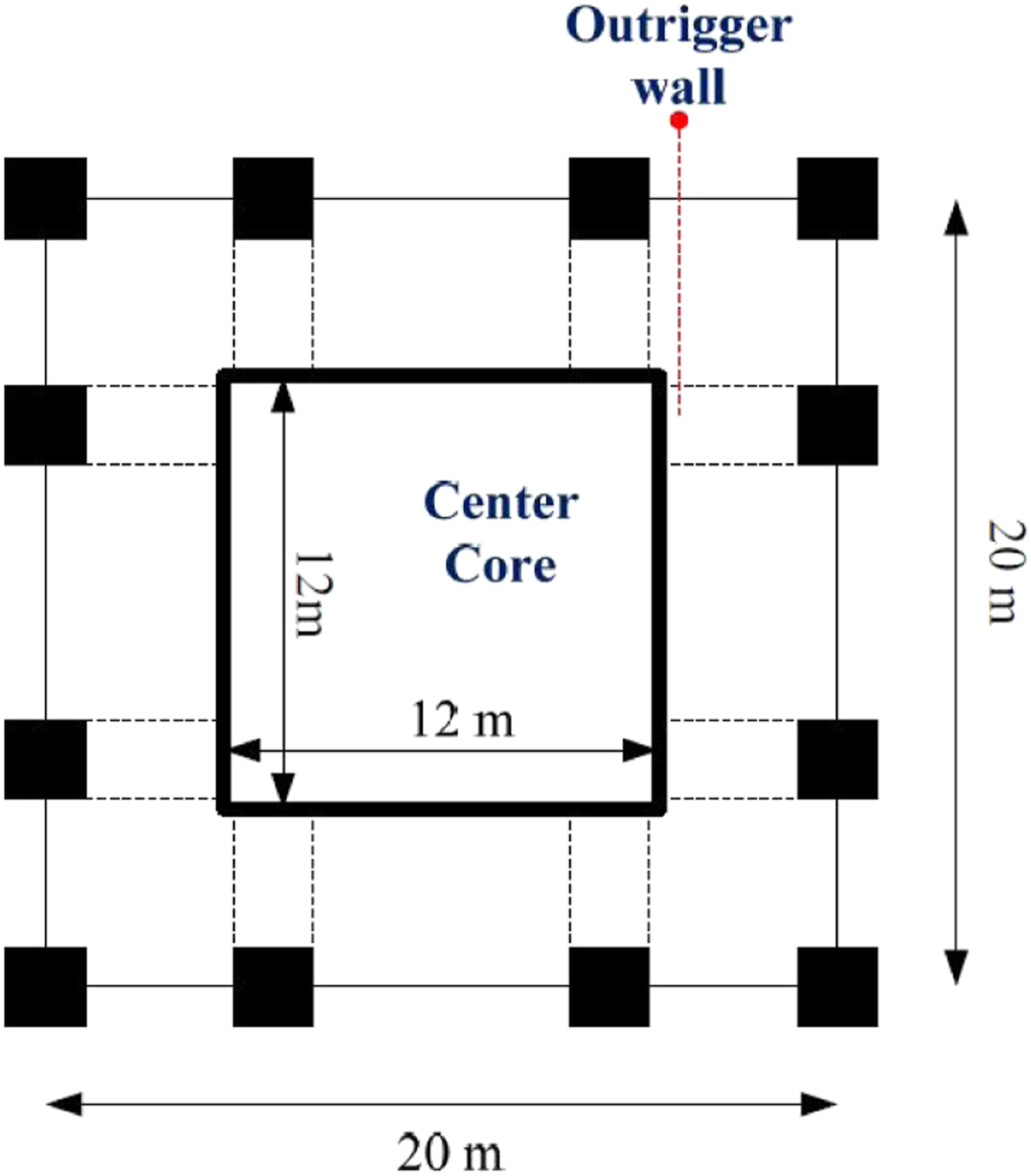
According to the definitions, the stiffness ratios are
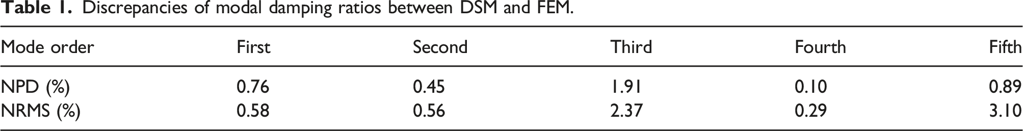
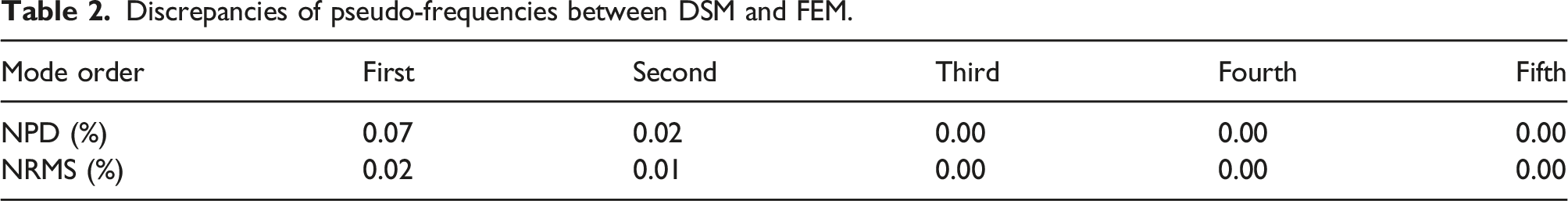
To quantify the discrepancies between the DSM and FEM analysis results, two quantitative indexes, namely, the normalized peak difference (NSP) and the normalized root mean square (NRMS), are used and defined as follows


Dynamic characteristic
The first five modal damping ratios and pseudo-frequencies calculated using both DSM and FEM versus non-dimensional damping ( Comparison of modal damping ratio and frequency between DSM and FEM. (a) Modal damping ratio. (b) Normalized frequency. Discrepancies of modal damping ratios between DSM and FEM. Discrepancies of pseudo-frequencies between DSM and FEM.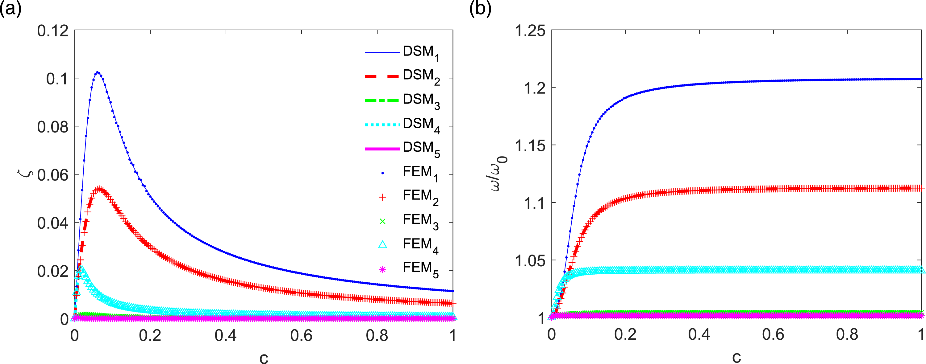
Dynamic response
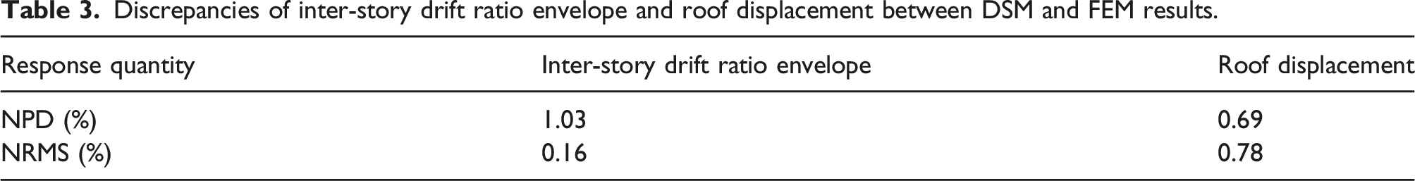
Figure 5 shows the envelop of inter-story drift angle and the time history dynamic response of roof displacement of such system subject to El Centro wave record with peak round acceleration (PGA) of 0.1 g ( Comparison of time history dynamic response of roof displacement between DSM and FEM under 0.1 g El Centro wave record. (a) Envelop of inter-story drift angle. (b) Time history of roof displacement. Discrepancies of inter-story drift ratio envelope and roof displacement between DSM and FEM results.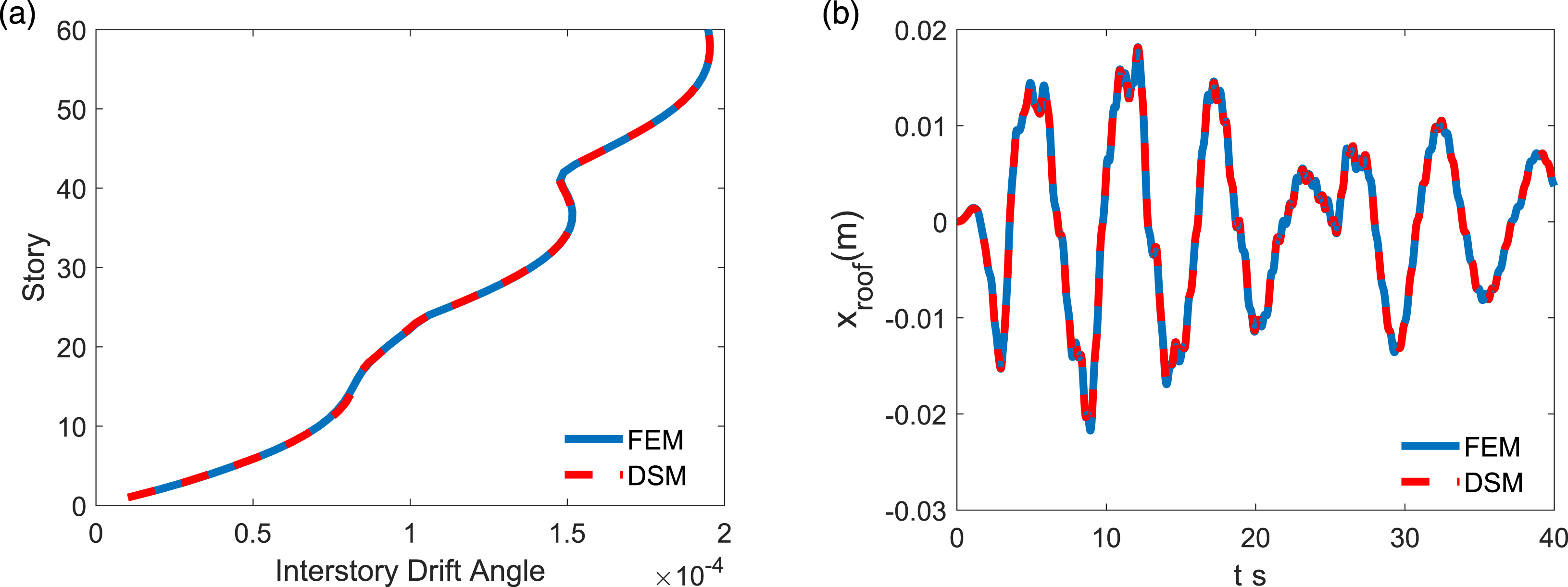
Stochastic response
In this section, the ground motion uncertainty is modeled by Kanai-Tajimi spectrum with parameters as natural frequency
Figure 6 compares the transfer function of the roof displacement to the ground acceleration calculated from the DSM and FEM between excitation frequency Transfer function of roof displacement to ground acceleration. (a) Magnitude. (b) Phase angle (rad). Discrepancies of magnitude and phase angle of transfer function of roof displacement to ground acceleration between DSM and FEM. Note: The phase angles at rounds 2, 6, and 11 Hz are removed from the comparison due to the reverse of direction.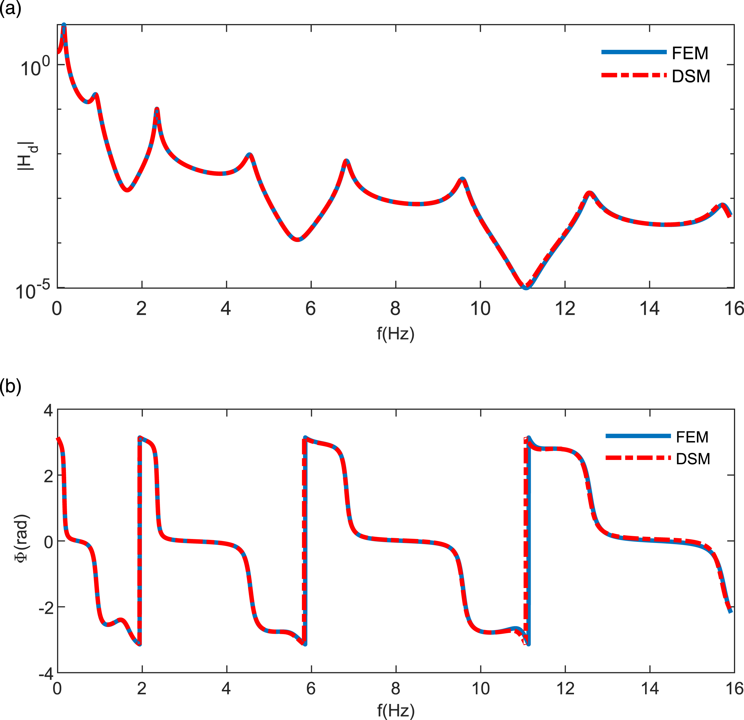
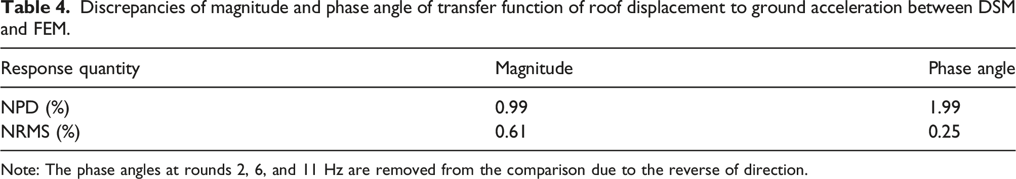
Figure 7 shows the response variance of roof displacement of the damped outrigger system versus damping subject to stochastic excitation following Kanai-Tajimi spectrum. Note that the optimal non-dimensional damping (see equation (19)) to minimize roof displacement is 0.08, rather than the optimal first modal damping (0.06), suggesting that the damping-based design could generally allow the systems to achieve good performance but might not be optimal to achieve design objectives. The corresponding FEM results from the solutions of the Lyapunov equation (see Refs. 78-80 for more details) are also plotted in Figure 7 for comparison. Again, the results from both methods match pretty well with the discrepancy metrics of NPD and NRMS being 0.11% and 0.05%, respectively. Response variance of roof displacement versus damping with Kanai-Tajimi spectrum parameters: 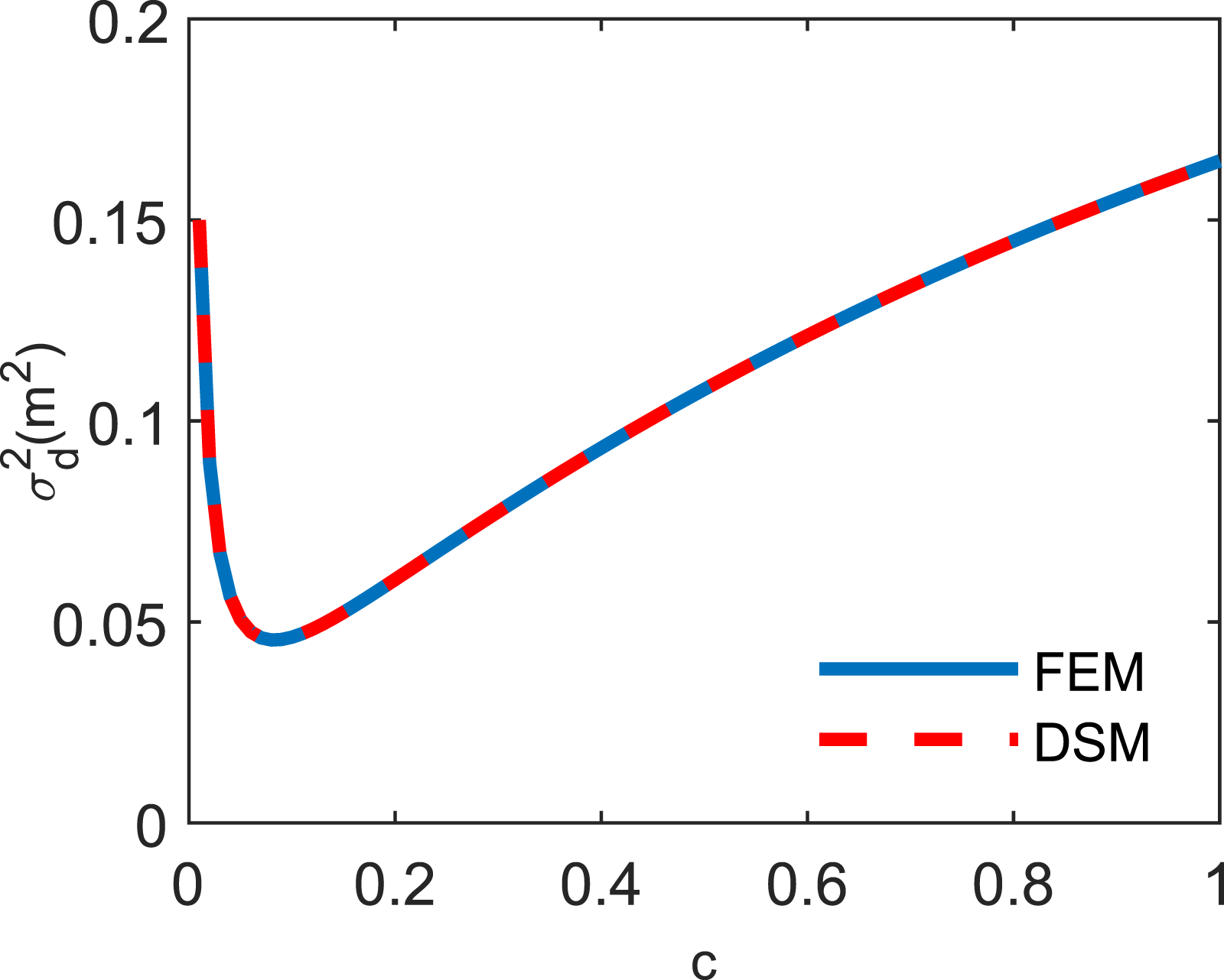
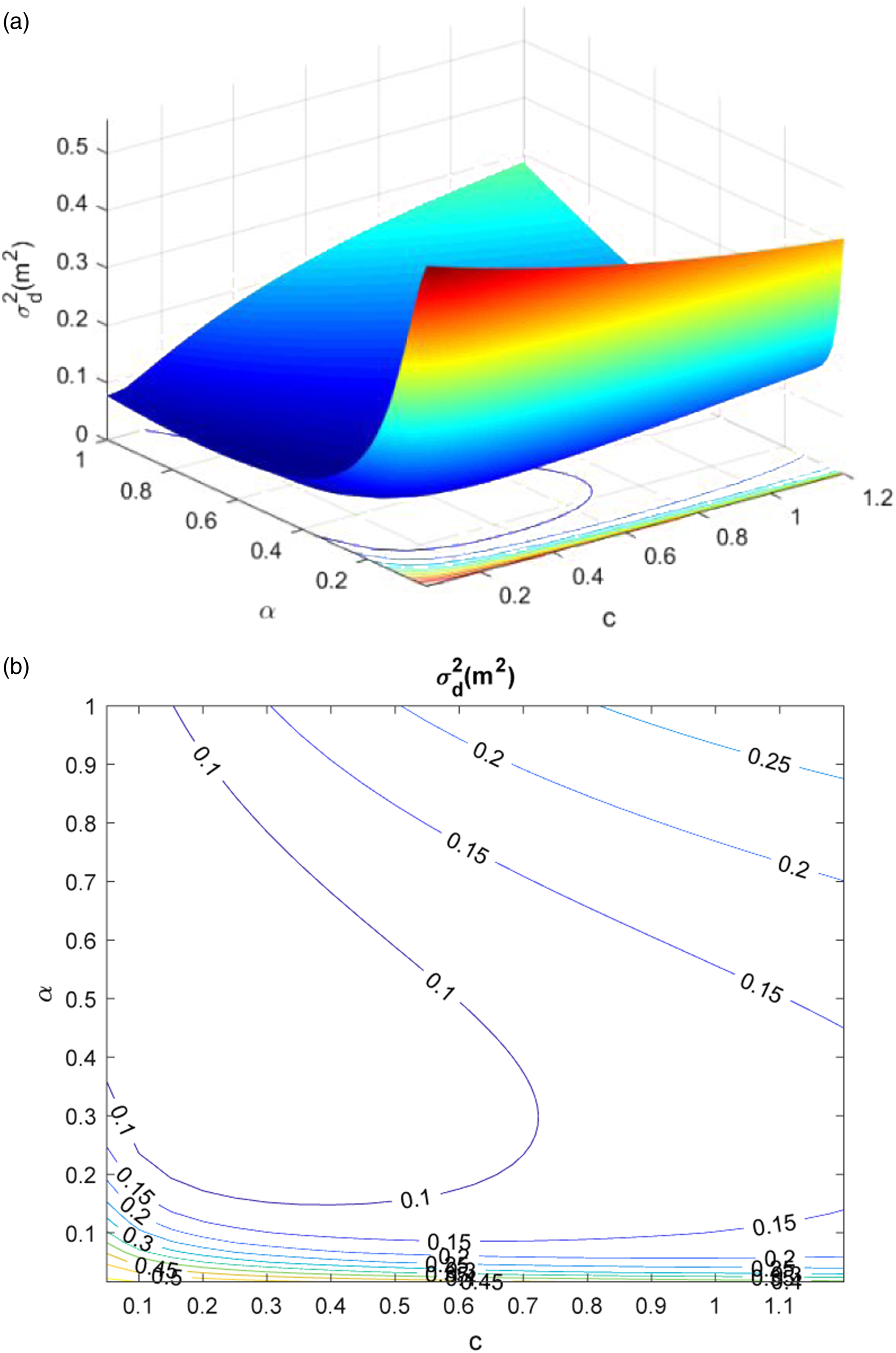
To investigate the influence of damped outrigger location, Figures 8 and 9 show the response variances of roof displacement versus damping coefficient and damped outrigger location by assuming only one damped outrigger is utilized. In calculation, the core is discretized into 60 elements as each story as a calculating point, that is, Response variance of roof displacement based on continuous model. (a) Surface plot. (b) Contour plot. Response variance of roof displacement based on FEM. (a) Surface plot. (b) Contour plot.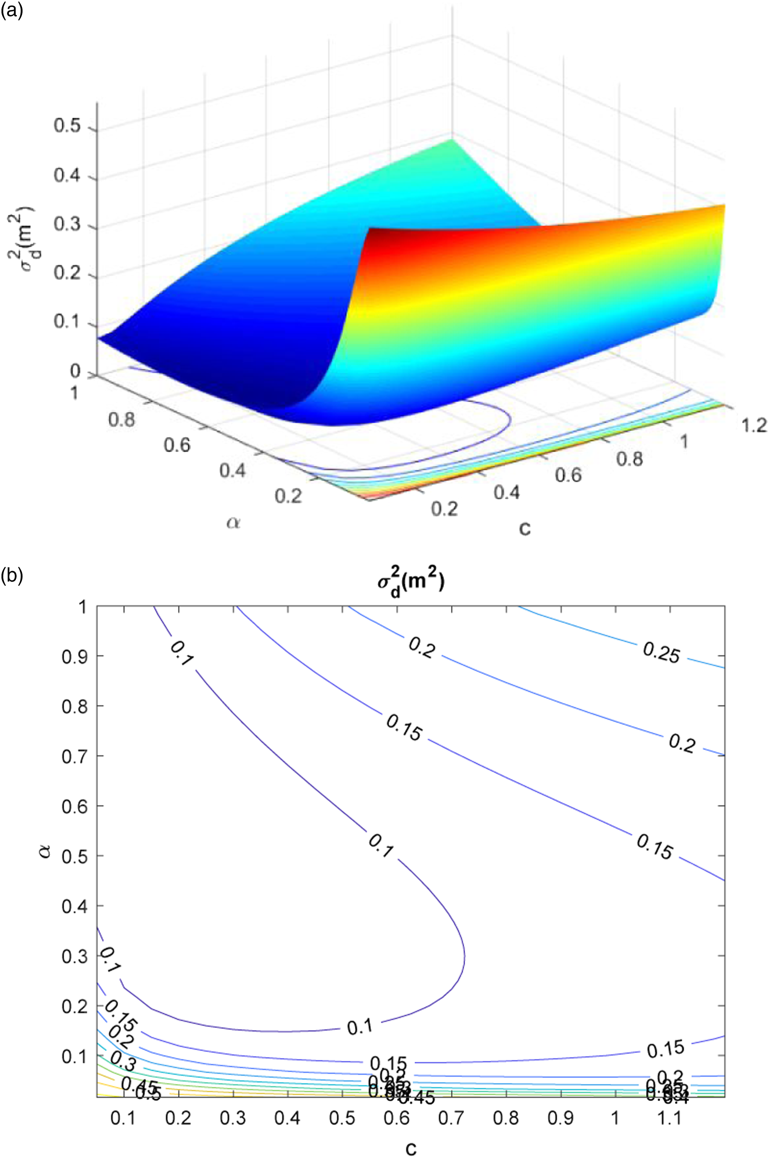
For the ease of discussion, Figure 10 further compares the results of two methods by fixing one factor, where FEM-N = j and DSM-N = j in Figure 10(a) represent the response variances of the roof displacement with the damped outrigger fixed at the j-th story using FEM and DSM, respectively, whereas FEM-c = j and DSM-c = j denote the corresponding results with the non-dimensional damping c = j from FEM and DSM, respectively. For instance, DSM-N = 30 and DSM-c = 0.2 correspond to the response variance of the roof displacement with the designs of the damped outrigger placed at the 30th floor and the non-dimensional viscous coefficient fixed at 0.2. In Figure 10(a), as the damping coefficient increases, the response variance of roof displacement reduces and then increase after it reaches its minima; Figure 10(b) shows a similar trend for damped outrigger position, though the sensitivity is much less than damping coefficient. Likewise, the response variances of roof displacement associated with viscous coefficient and the location of damped outriggers in Figures 8–10 obtained from DSM and FEM methods only have 0.11% and 0.05% differences according to the NSP and NRMS metrics, respectively. Influence of damping coefficient and damped outrigger location on the response variance of roof displacement. (a) Damping coefficient. (b) Damped outrigger location.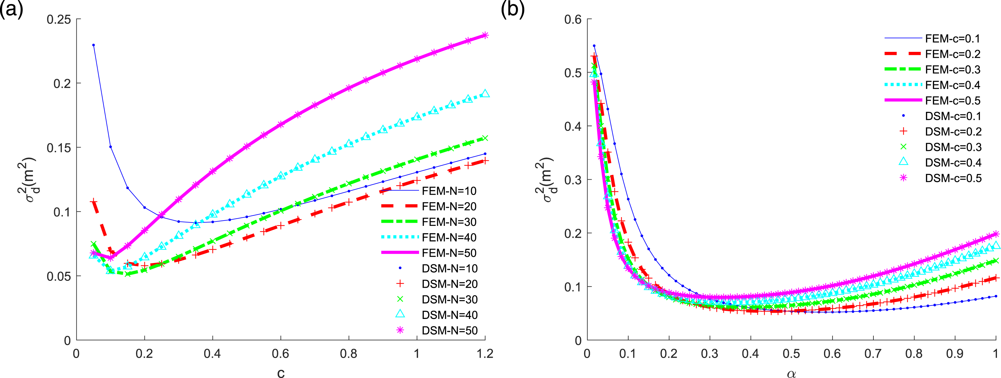
Conclusions
This study proposed a frequency domain-based analytical framework for the seismic performance of viscously damped outrigger systems. Based on a core–outrigger–damper–column simplified model, the global dynamic stiffness matrix was assembled from the core modeled as a Timoshenko beam, damped outriggers as complex rotational stiffness comprising outriggers, dampers, and perimeter columns, and inherent damping using Leung’s theory and modal damping construction. A general numerical method combing Wittrick-Williams algorithm and Newtonian iteration was developed to study the dynamic characteristic of such systems with multiple damped outriggers. The FFT and IFFT were then integrated with the principle of potential energy to obtain the equivalent nodal force and thus the time history response by transformations between time and frequency domains. Finally, the stochastic analysis was conducted via the transfer function resulting from the global stiffness matrix. The proposed approach was verified by comparison with the finite element method through a case study of a tall building implemented with viscously damped outriggers. This study showed that the proposed analytical framework could serve as a powerful tool for evaluating the performance of viscously damped outrigger systems.
Footnotes
Acknowledgment
The author gratefully acknowledges the insightful suggestions and encouragement from Prof. Quang Wang of Shantou University.
Declaration of conflicting interests
The author(s) declared no potential conflicts of interest with respect to the research, authorship, and/or publication of this article.
Funding
The author(s) disclosed receipt of the following financial support for the research, authorship, and/or publication of this article: This study received support from the Special Program of Guangdong Science and Technology in 2021 (grant no. 210715155861712).
In reference 80, slight changes are made to the article title to match the revised title of the reference.
Appendix
For
The shape functions are as follows
The equivalent nodal force is as follows