
Abstract
The disc spring system is applied to the vibration screen, which can effectively reduce the exciting force and improve screening capacity. In this work, the dynamic characteristics and screening performance of the disc spring vibration screen are studied. The modal simulation and experimental results show that the model vibration direction at first natural frequency is consistent with the working direction of the vibration screen. Moreover, the trajectory analysis and discrete element screening simulation prove that the disc spring vibration screen has better screening performance than the coil spring vibration screen. Eventually, by comparing required exciting force under the same amplitude, fatigue life of the spindle bearing, and energy consumption between the coil spring and disc spring vibration screen, it can be found that disc spring vibration screen has better mechanical properties, higher reliability, and lower energy consumption.
Keywords
Introduction
Screening operation is widely applied in metal metallurgy, mining, chemical industry, food processing, and public hazard treatment.1–3 Vibration screen is a type of engineering machinery that completes the screening process and improves the screening efficiency.4,5 With the reciprocating vibration of the screen mesh, the processes of loosening, layering, touching, and screening particles in vibration screen are completed. 6 The elliptical vibration screen has the characteristics of simple structure, stable working state, large processing capacity, easy operation and daily maintenance, so it is widely used in sand and gravel mining industry.7,8
The coli springs are adopted as elastic support elements in traditional elliptical vibration screens. This type of elastic elements has low stiffness, which makes the overall stiffness of the elliptical vibration screen low. 9 The natural frequency of the traditional elliptical vibration screen in the vibration direction is far lower than working frequency, which leads to a large exciting force to achieve the required amplitude. However, with the development of large-scale and high-speed vibrating screen, exciting force of vibrating screen is increasing to satisfy the required amplitude.10–12 The greater exciting force means more energy loss and higher vibration intensity, which will accelerate the fatigue damage of component and reduce the service life of the vibration screen. 13 Furthermore, the greater exciting force also brings more noise pollution and lower screening efficiency. 14 Therefore, the problems of structural optimization to reduce excitation force and improving the screening efficiency need to be further studied.
For structural optimization of vibration screen, Jiang and Zhou studied the kinematics and spatial behaviors of variable-amplitude equal-thickness elastic screen (VAETES) and vibration screen with elastic screen surface (EVS),15,16 respectively, and they effectively solved the problem of moist coal material accumulation and screen aperture blockage. A flip-flow screen with crankshaft-link structure (FFSCLS) proposed by Li has excellent performance for moist coal screening. 17 Improvement for design of beam structures in large vibrating screen considering bending and random vibration is studied by Peng and Liu, 18 which aims to conduct a systematic mechanics analysis of the beam structures and improve the design method. To solve the problem of damage due to large dynamic stress of the lateral plates during working process of the vibration screen, the natural modes and distribution of dynamic stress of lateral plates are calculated and analyzed, and the lateral plate structure is optimized by means of the improved genetic algorithm. 19 However, the above researches are mainly based on structural parameter design and kinematics characteristics, which do not directly solve the problem of excessive exciting force.
For improving the screening efficiency, the combined effects of vibration parameters on the elliptical screening processes are analyzed based on the Taguchi orthogonal experiment method by Zhao et al. 20 A hybrid MACO-GBDT algorithm based on the Ant Colony Optimization is proposed for optimizing the screening performance of elliptical vibration screen by Chen et al. 21 The above researches are achieved by changing the screen parameters to increasing the screening efficiency. Nevertheless, there are few studies focusing on optimizing the structure of the vibration screen to improve the corresponding screening efficiency.
Notably, the disc spring system has been proven to have high stiffness and excellent dynamic characteristics in our previous studies, 22 which can effectively reduce the exciting force by resonance amplification amplitude and maintain a stable working state.23,24 Nevertheless, the dynamic characteristics and screening performance of the disc spring vibration screen still need to be further explored.
In this work, the disc spring system is applied to the elliptical vibration screen as an elastic support component. The dynamic characteristics of the disc spring vibration screen are studied by numerical analysis, finite element simulation, and experiment. Then, the natural frequencies, mode shapes, and amplitudes at different positions are obtained by modal and amplitude test. Moreover, the screening processes of the coil spring and disc spring vibration screen are analyzed through the amplitude synthesis trajectory. Furthermore, the modeling and screening simulation of the coil spring and disc spring vibration screen are carried out by discrete element method, and the screening efficiency and time of two vibration screen are obtained and compared. Eventually, dynamic characteristics, screening capacity, fatigue life, and energy consumption are compared between coil spring vibration screen and disc spring vibration screen.
Method and methodology
Object description and mechanics analysis
Based on the research on the dynamic characteristics of the disc spring system,
25
the disc spring vibration screen is designed as shown in Figure 1. The disc spring vibration screen has three layers with the length of 6.5 meters and width of 4.2 meters. Eight groups of the disc spring system are used as elastic support of vibration screen, and the mass of whole disc spring vibration screen is 5.5 t. The exciting force of large vibration screen is generated by the eccentric block. The disc spring used in our study is heavy, and the edge thickness of the disc spring is 8 mm. Meanwhile, the disc springs at two adjacent ends are tightly locked. Thus, the disc spring is unlikely to rotate under working condition, in which the velocity of air fluid has little change. Therefore, the aeroelastic effects
26
have little influence on the disc spring system and can be neglected. Experimental prototype of disk spring vibration screen.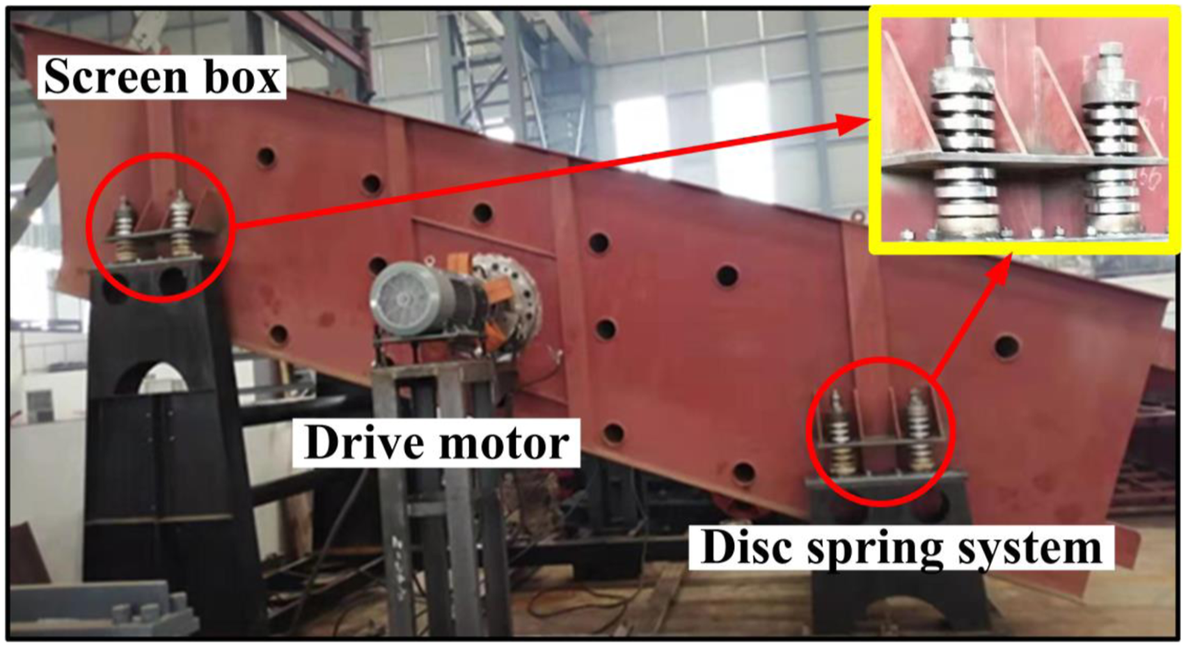
When the disc spring system is compressed, some of the kinetic energy of the vibration screen is converted into internal energy and stored in the disc spring system. When the disc spring system returns to its original length, the internal energy stored in the disc spring system is converted into kinetic energy to lift up the vibration screen. The disc spring system has larger rigidity and compression than coil spring system. According to the energy harvesting theory, 27 the disc spring system can convert more energy than the coil spring system.
The large disc spring vibration screen belongs to the near resonance screen, so its equation of motion can be approximately replaced by vibration equation of the inertia vibration screen. The dynamic model of the disc spring vibration screen is established as shown in Figure 2. Dynamic model of disk spring vibration screen.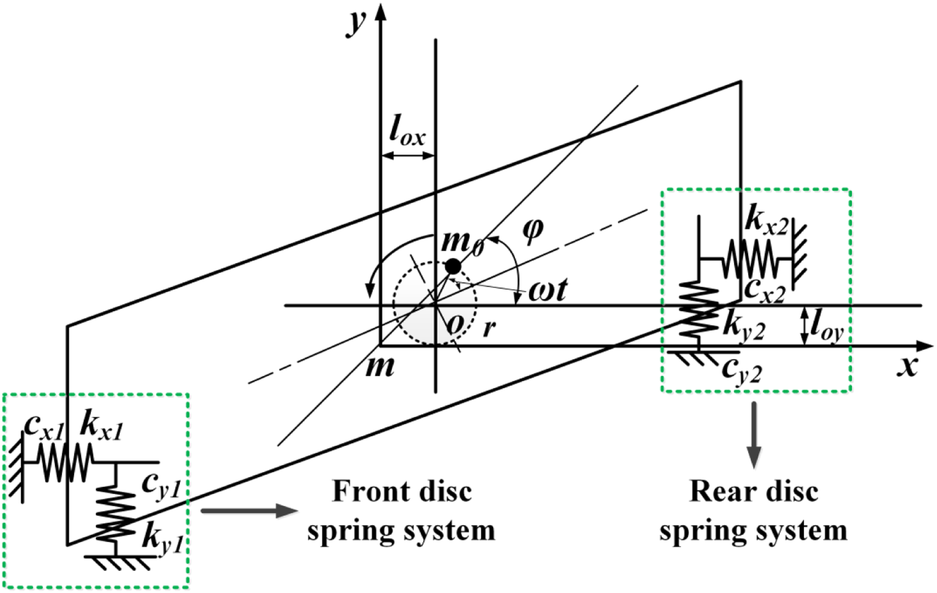
The synthetic inertia force generated by the eccentric block on the rotating shaft is shown in the equation (1)

The relative inertia force in X and Y direction are shown as
28

In equation (2), F
x
(t) and F
y
(t) are inertia force of eccentric block in X and Y direction rotating relative to the axis. Referring to the Figure 2, the force equations of disc spring system along X and Y directions are obtained in equation (3)
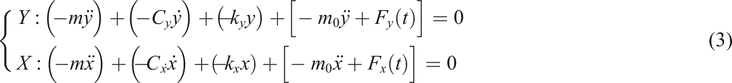
In equation (3), the masses of the disc spring vibration screen and eccentric block are shown as
The vibration equations of disc spring system along X and Y directions and rocking vibration equation around the Z axis are obtained in equation (4)
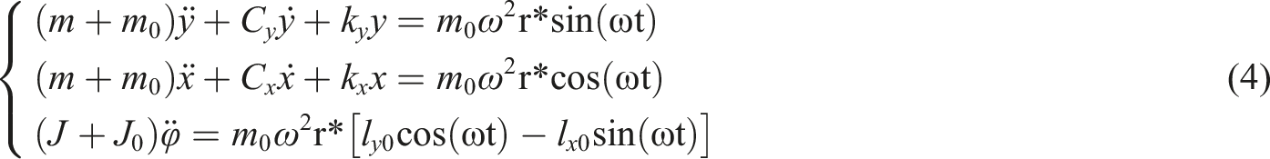
J and J
0
are moment of inertia of the disc spring vibration system and eccentric block to centroid of system. The l
x0
and l
y0
are the distance of eccentric block rotating axis to system centroid along X and Y directions. The
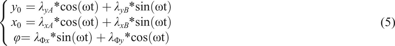
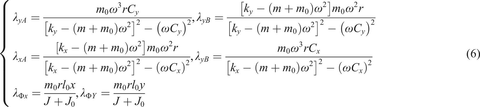
The equation (5) is differentiated twice and brought into equation (6). The equation (6) can be obtained
The equation of motion for any point on the vibration system model is shown as equation (7)

Modal simulation and experiment
Modal analysis is one of the most effective methods to study the dynamic characteristics of structures,
29
and each mode has a specific natural frequency and mode shape to reflect the natural vibration characteristics of its mechanical structure.
30
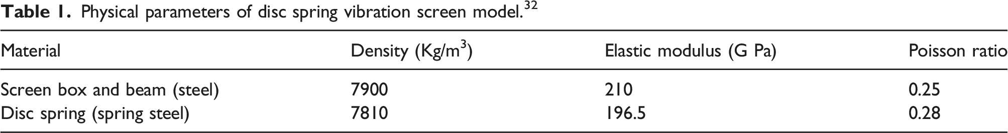
To simplify the model and improve the simulation efficiency, the actual vibration screen is simplified as follows: (1) the exciting force generated by the eccentric block is replaced by the sinusoidal force applied to drive shaft; (2) the fixed support is replaced by surface constraints applied under each disc spring system; (3) the screen box is fixedly connected with the beam, transmission shaft, and disc spring system. The finite element model of vibration screen is shown in Figure 3, and Table 1 shows the physical parameters of disc spring vibration screen model. Finite element model of disk spring vibration screen. Physical parameters of disc spring vibration screen model.
32
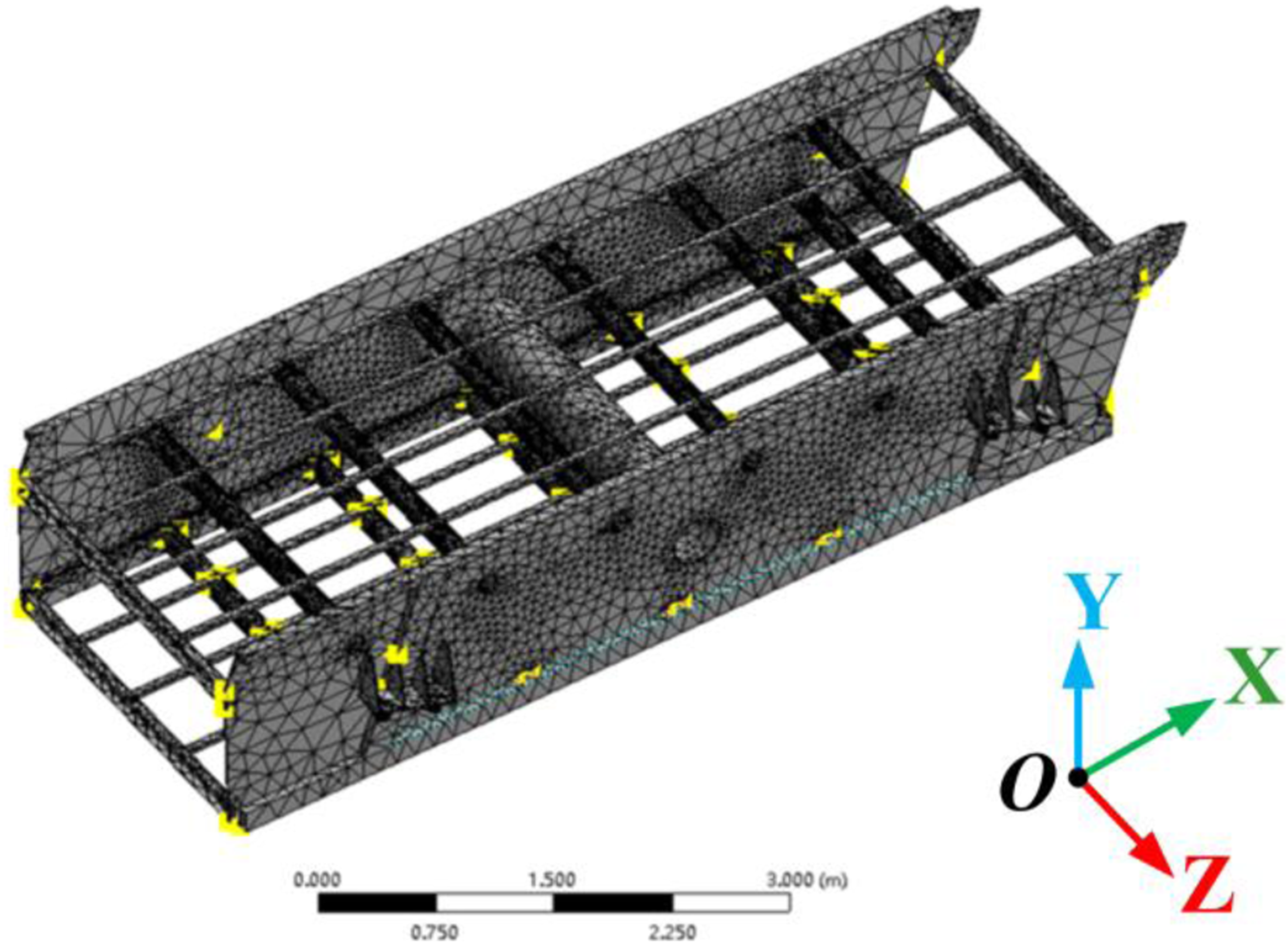
The structural steel with a density of 7900 kg/m3 is selected in simulation to make up the mass difference between simplified model and actual vibration screen. And the actual density of steel used in the vibration screen is only about 7300 kg/m3. Therefore, there is little mass difference between simplified model and actual vibration screen.
Reasonable boundary conditions are applied after the modeling is completed. All parts of the vibrating screen are in surface-to-surface contact, and the bottom ends of the eight disc spring groups are all set as fixed constraints. The weak spring setting is turned on to prevent the calculation from converging due to excessive displacement deformation of the shaker. After preprocessing, the Block Lanczos algorithm 31 is adopted for modal simulation.
To explore the modal characteristics of the disc spring vibration screen, the experiment platform of the modal test is built in Figure 4(a). The impacting excitation is generated by a heavy hammer in the upper left corner of Figure 4(a). The vibration signals are received by the acceleration sensor pasted on the surface of the vibration screen box. The acceleration data are monitored and collected by the Siemens data acquisition instrument (LMS SCADAS Mobile SCM05).
33
The natural frequency and mode shapes are obtained by modal analysis and processing of acceleration signal. Specific experimental equipment and scenarios of (a) modal test and (b) amplitude test.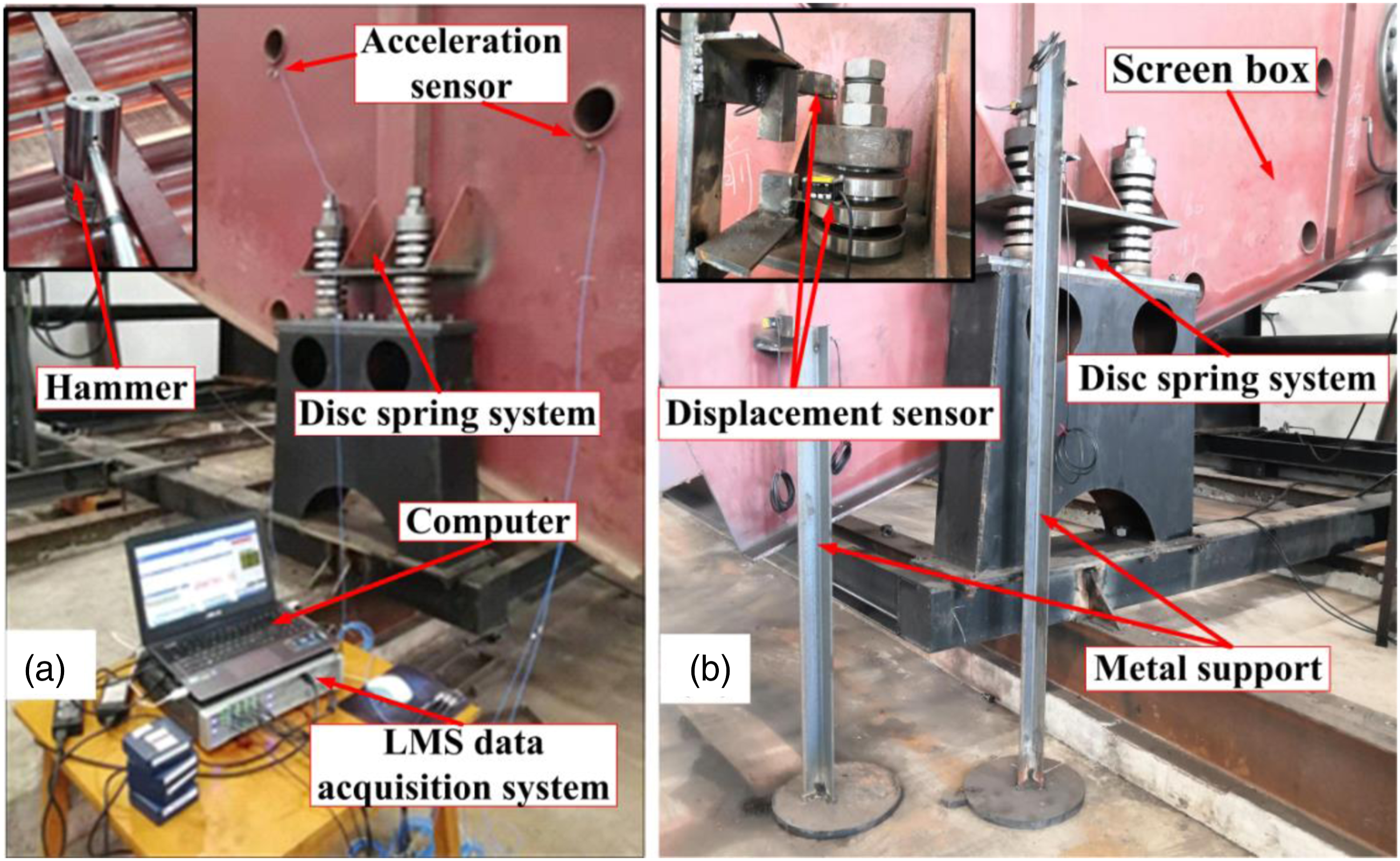
Amplitude simulation and experiment
To further study the dynamic characteristics of the disc spring vibration screen, the amplitude simulation and experiment are carried out. The disc spring system model is established in modal analysis. The transient analysis module in finite element software is used to simulate the working process of vibration system. 34 By replacing exciting force produced by eccentric block, the dynamic force in the form of sine wave is exerted on the four corners of upper surface in disc spring system. The frequency of dynamic force is same as the working frequency, which is 16.33 Hz (980 r/min). The full algorithm 35 is adopted in the transient analysis. The damping coefficient of disc spring system is set to be 0.1. 36
The amplitude experimental equipment and scenarios are shown in Figure 4(b). The dynamic force is produced by rotation of eccentric block. There are two laser displacement sensors supported by metal frames to measure the amplitudes in X and Y direction, respectively. The value of amplitude is collected by signal acquisition module in LMS.
Discrete element method simulation of screening process
Besides the dynamic characteristics of the disc spring vibration screen, the screening performance is also studied by discrete element method.
37
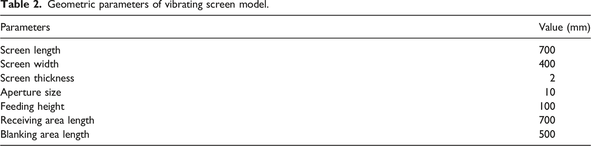
Simplified vibration screen in Figure 5 is mainly composed of feed port, screen box, screen mesh, and bottom box. The geometric parameters of the vibration screen model are shown in Table 2. It is noteworthy that the screen box is designed to be semi-closed to present the particle splashing process. There will be a small amount of particles moving out of the screen model in simulation, which is consistent with the actual industrial production. The bottom box is divided into two parts: receiving are and blanking area. The undersized fine particles are collected in receiving area and oversized coarse particles are collected in blanking area. Discrete element model of vibrating screen (dimension in mm). Geometric parameters of vibrating screen model.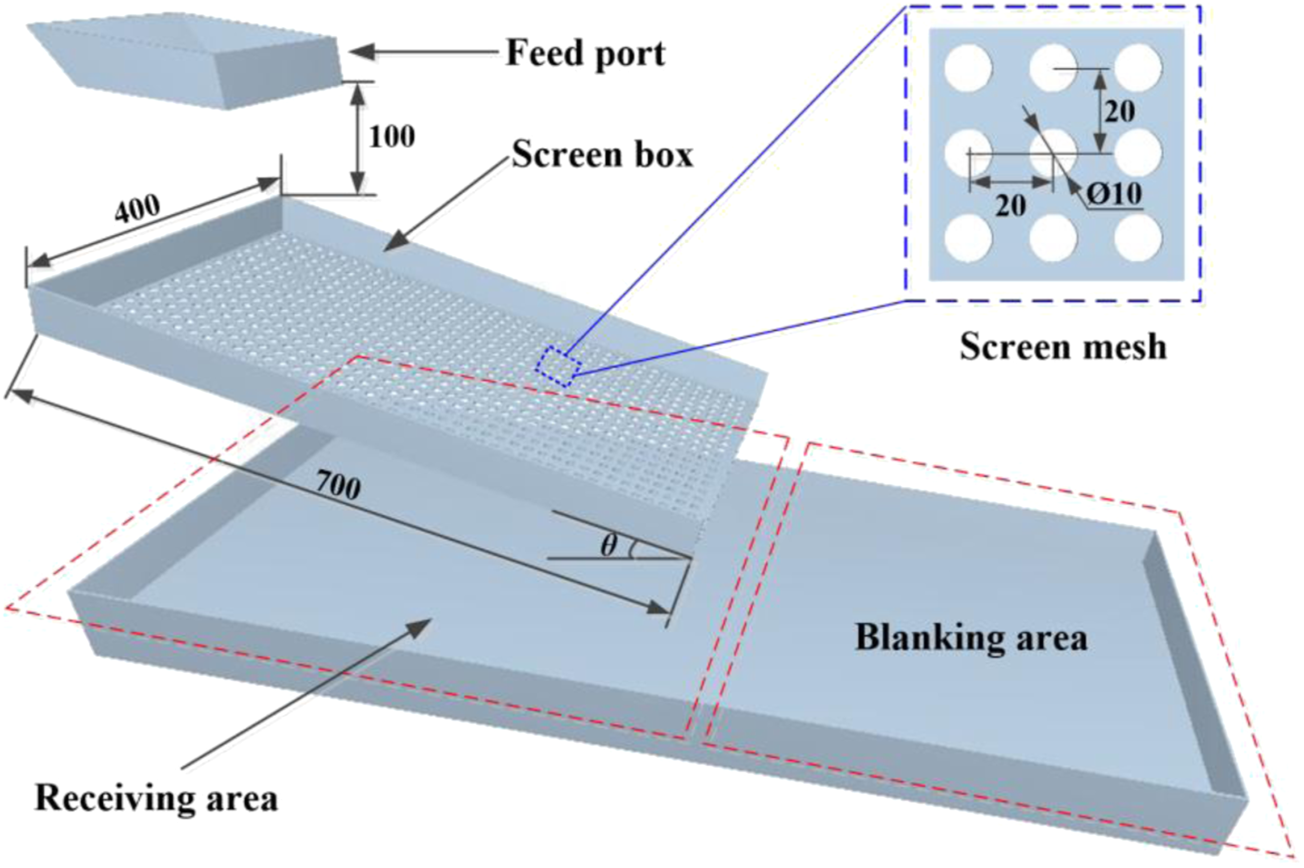
The three different shapes of wet sand and gravel particles are modeled and the corresponding discrete element model is modeled by filling ball method.
38
The modeling process is shown in Figure 6. Discrete element model of wet sand and gravel particles with different shapes: (a) flat particle, (b) triangular cone particle, and (c) ellipsoid particle.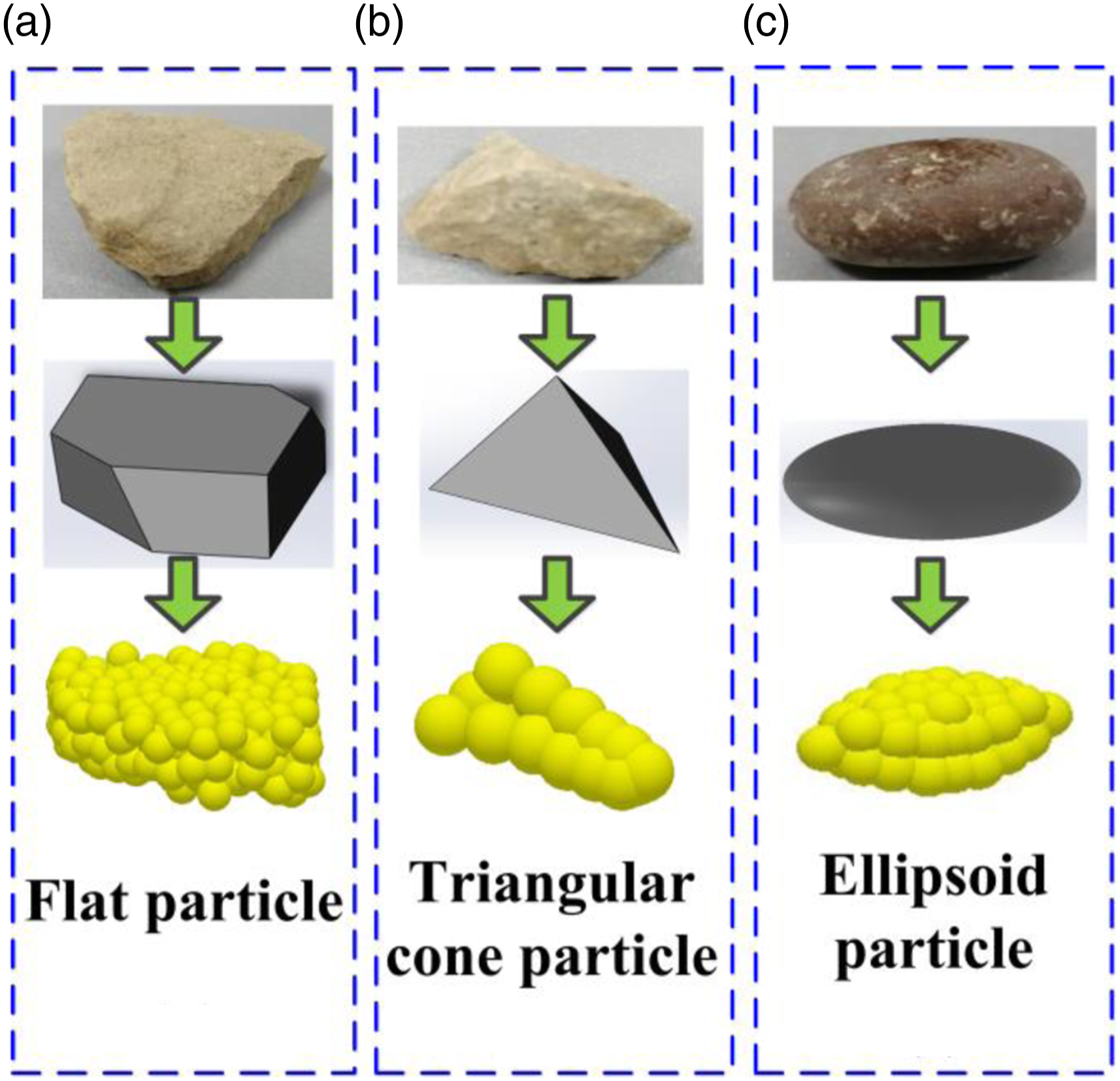
Results and discussion
Dynamics characteristics analysis
The external diameter of the disc spring is 125 mm while internal diameter of the disc spring is 61 mm. The vertical rigidity of a single disc spring is 44,207 N/mm, and the mass of a single disc spring is 0.587 kg. According to the frequency test method in references 39 and 40, the first-order resonant frequency of single disc spring is 1381.86 Hz.
Meanwhile, the mode shapes and frequencies of the vibration screen under first four-order modal are shown in Figure 7(a)–(d). The gray shading represents the mode shape of the vibrating screen in static state while the color images represent the mode shape at the maximum deformation of the vibration screen. As can be seen from Figure 7(a), the vibration screen vibrates up and down along the Z direction at the first-order natural frequency of 16.061 Hz. At this time, the disc spring group undergoes tensile and compressive deformation along the Z direction while the screen box and beam both translate only along the Z direction. The second-order natural frequency of the vibration screen is 20.256 Hz, at which the screen box swings along the Y direction, and the maximum swing is located at the middle beam of the vibrating screen as shown in Figure 7(b). It can be seen from Figure 7(c) that the center of the vibration screen does not move at the third-order natural frequency while the two ends of the vibration screen warp. Meanwhile, it can be seen from Figure 7(d) that the out-of-phase warping motion occurs around the center of the vibration screen on both sides of the screen box of the vibration screen at the fourth-order natural frequency. First four mode shapes and natural frequencies in simulation.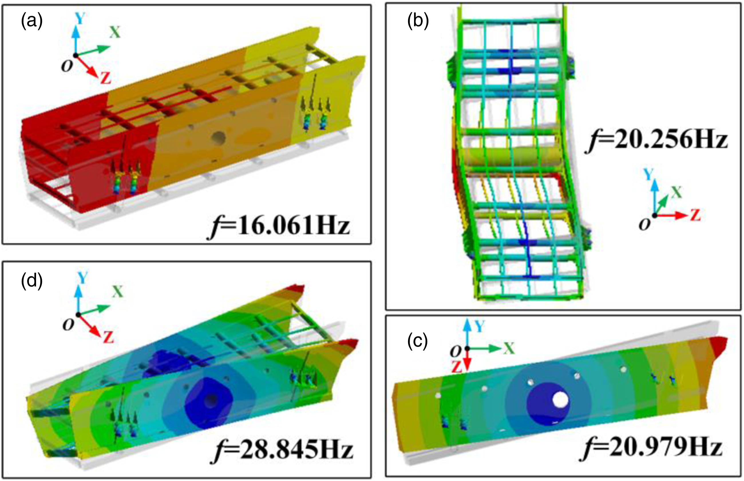
In general, it can be seen that the whole vibration screen moves up and down along the Z direction under the first-order vibration mode, which is consistent with the actual movement direction of the vibration screen, and is conducive to the loosening and screening of materials. At the same time, the first-order natural frequency of 16.061 Hz is close to the working frequency of 16.3 Hz. Thus, a smaller excitation force is required to obtain larger amplitude in the Z direction by resonance. It is noteworthy that deformation mode occurs at the first natural frequency. However, the displacement of rigid body modes is far less than that of deformation mode on screen box. Meanwhile, the stress caused by deformation is within limit of yielding of steel in screen box. Of course, the structural fatigue damage caused by deformation mode is worthy of attention. At present, the effective solution to avoid deformation mode of the screen box is to improve the structural rigidity of the overall screen box, which is the key problem we are focusing on.
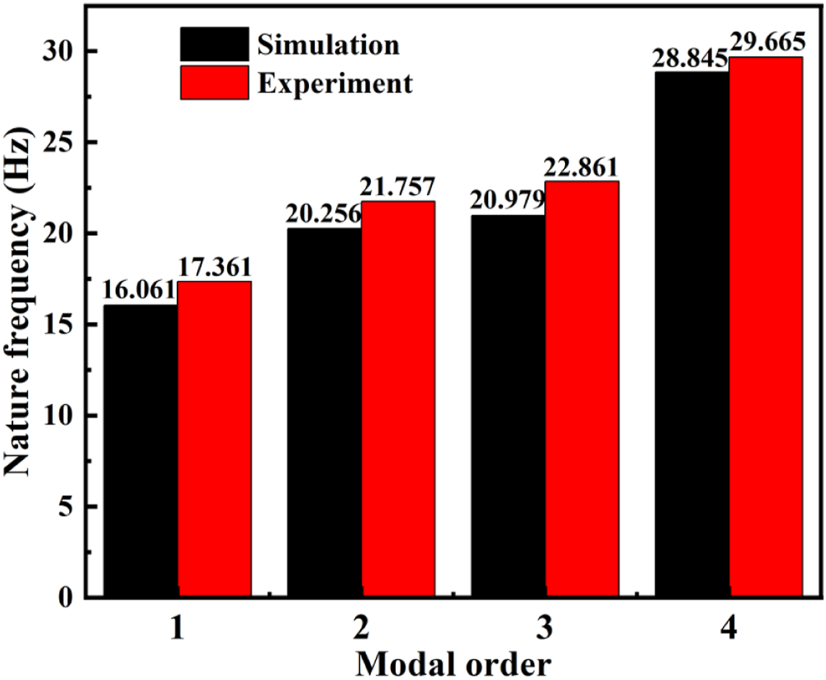
The first four mode shapes and natural frequencies in experiment are shown in Figure 8. To more intuitively and clearly show the vibration shape under each order mode in the vibration screen experiment, the black wire frame in Figure 8 represents the vibration shape of the vibration screen in static state while the yellow wire frame represents the vibration shape at the maximum deformation of the vibration screen. Due to the complex modal shape of model, it is difficult to show the distortion of the model in experiment with conventional angle picture. The modal shape (b) has been properly modified. The above treatment does not affect the authenticity of the test results. Obviously, it can be seen that mode shape of the vibration screen in simulation is in good agreement with that in experiment. At the same time, the comparison of natural frequencies between simulation and experiment is shown in Figure 9. It can be seen from Figure 9 that the simulation natural frequency is slightly higher than in experiment. The damping is ignored in the modal simulation, which will further cause the calculated value to be higher than the actual value. However, the effect of damping on the modal frequency of disc spring vibration screen is far less than that of rigidity. To ensure the good mechanical performance of the disc spring system and convenience of assembly, a preload is applied when the disc spring system is assembled. The disc spring system with preload has greater vertical rigidity, which leads to higher nature frequency in experimental than that in simulation. Overall, there is little difference between simulation value and experimental value. This shows that the simulation and experiment of the vibration screen have good consistency, and the established finite element model can simulate the screening experiment of the vibration screen well. First four mode shapes and natural frequencies of the disc spring vibration screen in experiment. First four natural frequencies of the disc spring vibration screen in simulation and experiment.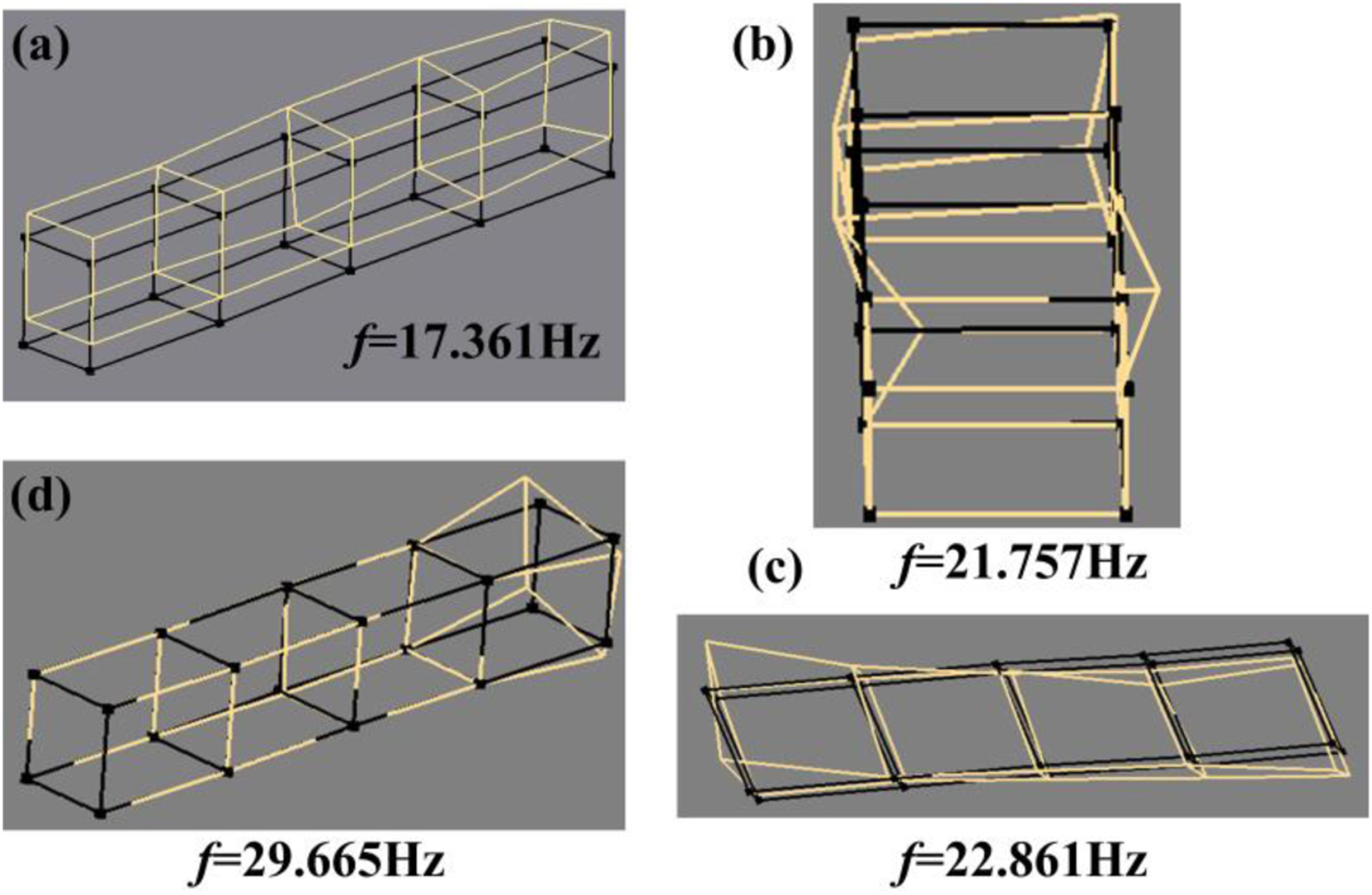
To obtain the vertical and horizontal amplitudes of the vibrating screen under working condition, the amplitude simulation and experiment of vibration screen are carried out. Figure 10 shows the simulation and experimental amplitudes of the disc spring vibration screen at different positions. The black curve represents the amplitude of vibration screen in the Z direction while the red line represents that in X direction. It can be seen from Figure 10(a), (c), and (e) that the simulated amplitudes of the vibration screen in the Z and X directions are all sinusoidal waveforms, and the waveforms are very stable. The maximum amplitude in simulation along the Z direction is 9.6 mm while that along X direction is 3.6 mm. The corresponding experimental amplitudes are shown in Figure 10(b), (d), and (f). It can be seen that the Z-direction and X-direction amplitude waveforms are also sinusoidal waveforms, but some modulation phenomena appear. The reason for this phenomenon is that the working vibration screen causes the vibration of the foundation, which causes the displacement sensor to shake. So the displacement has small fluctuations, but the error is within allowable range. The maximum amplitude in experiment along the Z direction is 8.8 mm, and that along the X direction is 3.2 mm. By comparing the amplitudes in simulation and experiment in Figure 10, it can be found that the two have good consistency, which further illustrates the accuracy of the simulation. Amplitude in Y direction and X direction at different position of vibration screen in simulation ((a), (c), and (e)) and experiment ((b), (d), and (f)).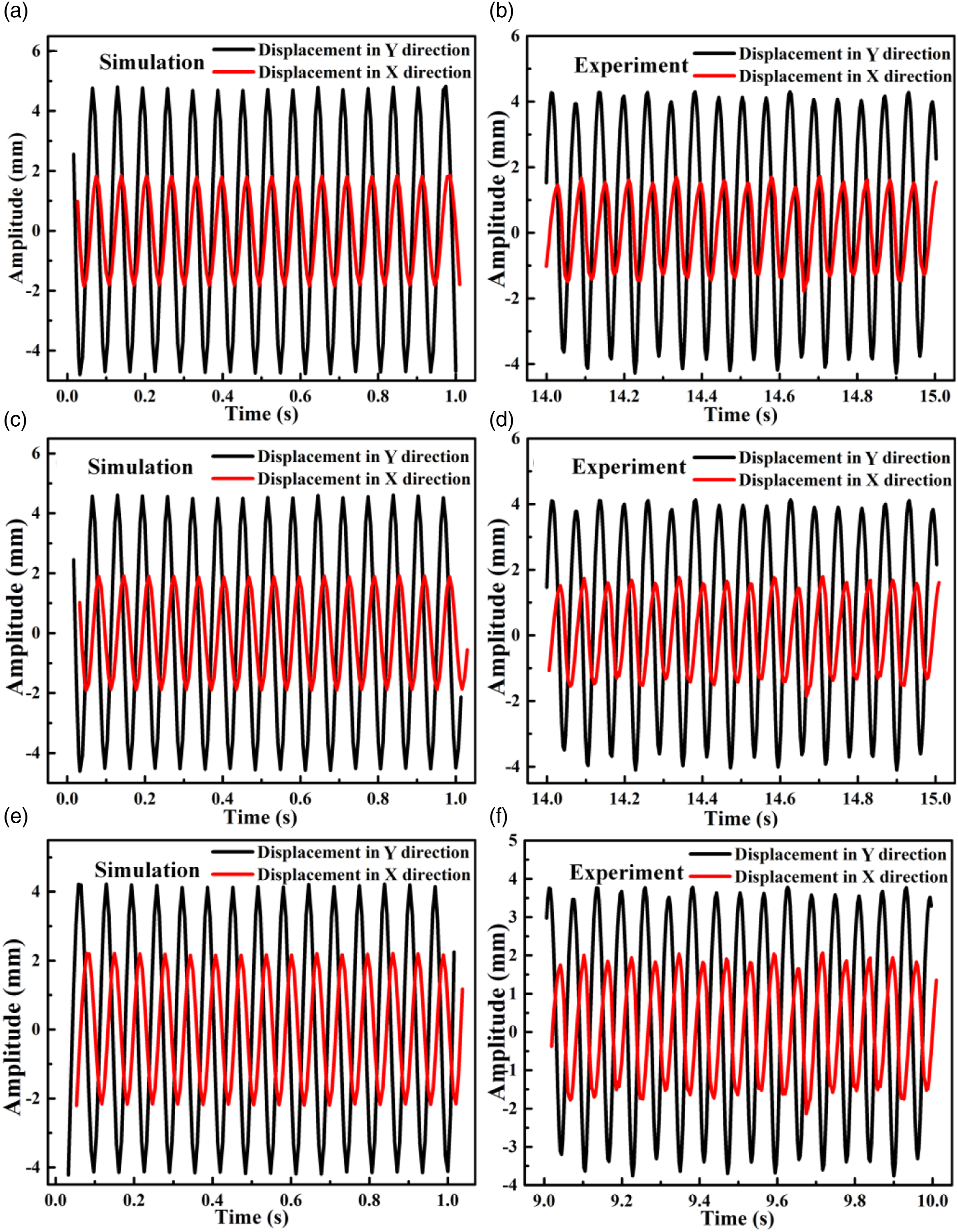
Screening mode analysis
According to the horizontal and vertical amplitude curves of the disc spring vibration screen in Figure 10, the vibration trajectories at different positions of the disc spring vibration screen are synthesized in Figure 11. The motion trajectories of the feed port, middle of screen box, and discharge outlet are shown in Figure 11(a), (b), and (c), respectively. It can be seen from Figure 11 that the trajectories of spring vibration screen gradually rotate clockwise, and the minimum axis radius of the elliptical trajectory slightly increases. Vibration trajectory of disk spring vibration screen in experiment: (a) feeding port, (b) middle of screen box, and (c) discharge outlet.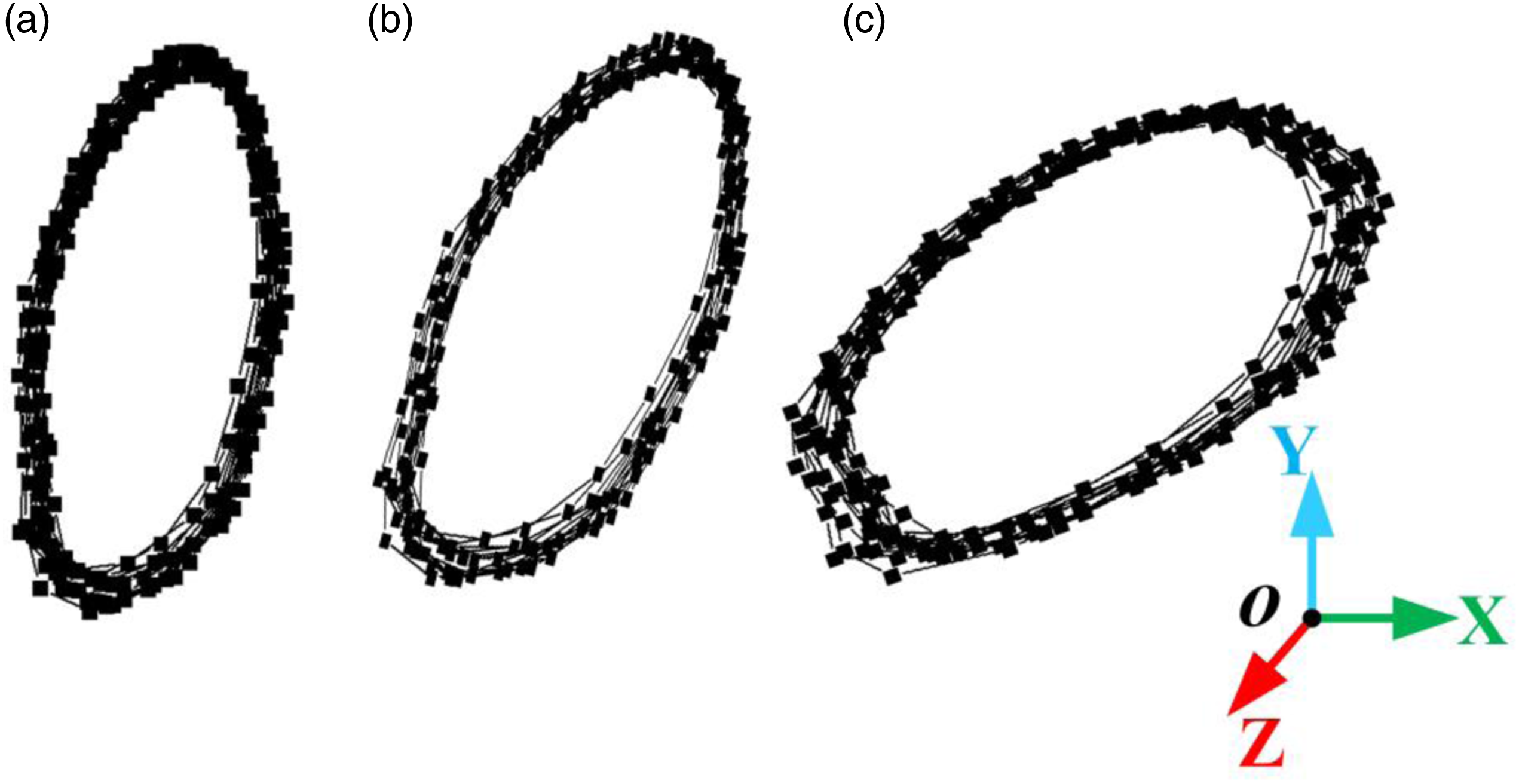
To further explore the similarities and differences between the motion trajectories of the disc spring vibration screen and the coil spring vibration screen on the screening efficiency, the wet sand and gravel screening process is studied by discrete element method.
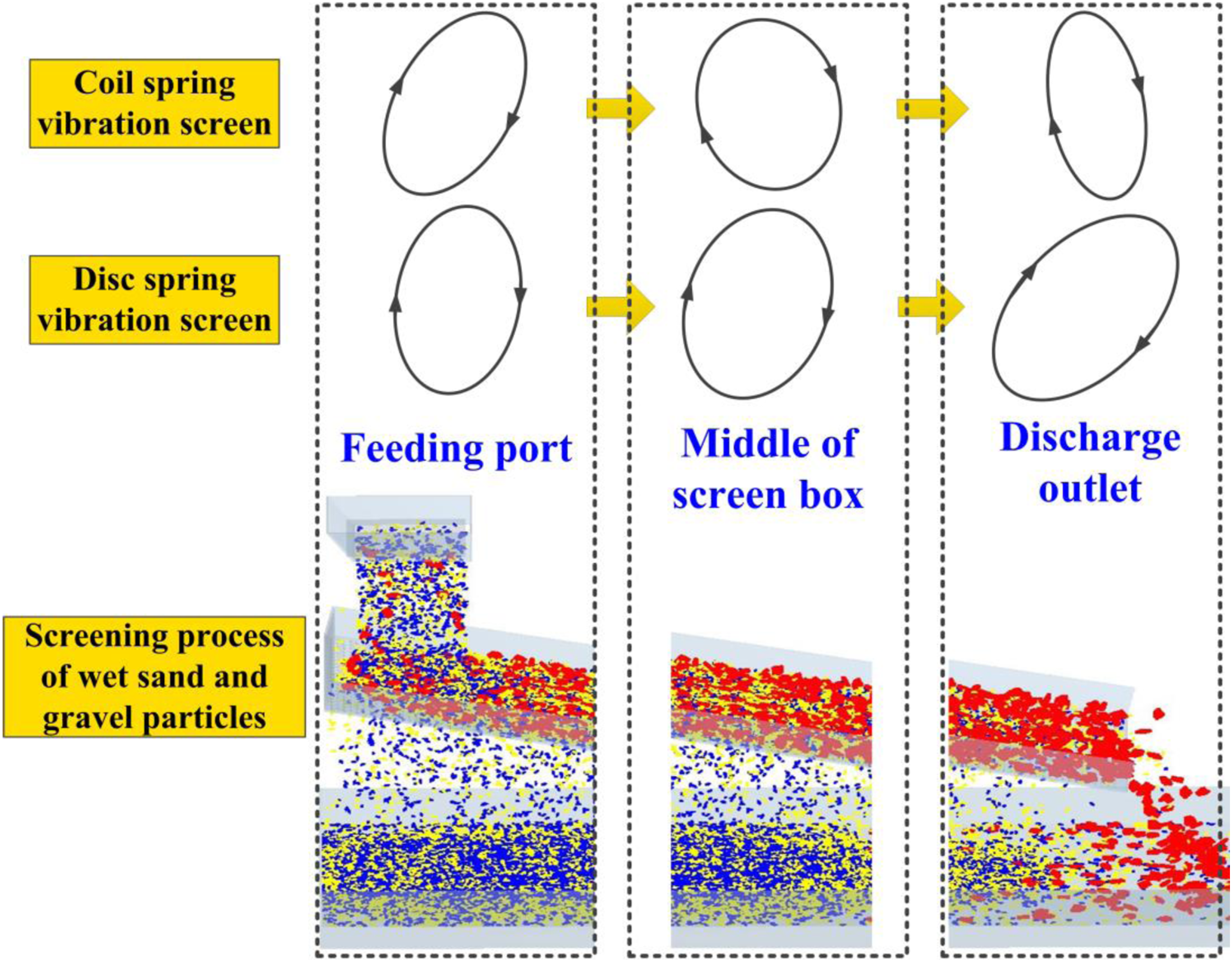
Figure 12 shows the trajectories of the coil vibration screen and the disc spring vibration screen at feeding port, middle of screen box, and discharge outlet. Meanwhile, the screening process of wet sand and gravel particles corresponding to the different position is presented at the bottom of Figure 12. The trajectories of coil spring vibration screen at different positions refer to the experimental study of circular vibration screen by Zhao.
41
It can be seen from Figure 12 that the trajectories of the vibration screen at three positions are all elliptical and move clockwise. However, there are also some differences between the trajectories of the coil spring vibration screen and the disc spring vibration screen: (1) At the feeding port, the vertical component of the elliptical trajectory of the disc spring vibration screen is larger than that of the coil spring vibration. However, the horizontal component of that of the disc spring vibration screen is smaller. It can be observed from the screening process of wet sand and gravel particles that the feeding port is located in the area with a large number of fine particles passing through the screen. At this time, wet sand and gravel particles have just entered in screen box, and the large vertical movement of the screen surface can contribute to quickly loosening of wet sand and gravel particles. The greater the degree of particle looseness leads to better screening performance. Therefore, the change of the trajectory at feeding port of the disc spring vibration screen is conducive to the screening of fine particles, so as to improve the screening efficiency. (2) At the middle of screen box, the elliptical trajectory of the coil spring vibration screen rotates counter-clockwise by nearly 90°, and the horizontal component of the amplitude further increases, which results in slowing down of the horizontal movement of particles on the screen surface. Although the residence time of particles can be prolonged and the probability of screening can be increased, it also extends the screening time and reduces the screening efficiency. However, the trajectory of the disc spring vibration screen rotates slightly clockwise. The large vertical component of this trajectory is still maintained, while the horizontal component increases slightly. The types of trajectory result in high screening efficiency of fine particles in middle of the screen box, while accelerating the fluidity of wet sand and gravel particles. (3) At the discharge outlet, the vertical component of elliptical trajectory of the coil spring vibration screen increases while the horizontal component decreases. However, the trajectory of the disc spring vibration screen at discharge outlet continues to rotate clockwise, and the horizontal component of that increases significantly. It can be observed from the screening process that when the particles move to discharge outlet, most of the fine particles have been sieved. At this moment, there are mainly particles with large size on the screen surface. Therefore, increasing horizontal amplitude at the discharge port will lead the large size particles to faster discharging, avoiding accumulation, improving the handing capacity, and increasing the treatment efficiency. Screening process trajectory of disc spring vibration screen and coil vibration screen.
The above motion trajectory analysis of the coil spring and disc spring vibration screen indicates that motion trajectory of disc spring vibration screen can obtain higher screening efficiency and greater output.
Dynamic parameters in coil spring and disc spring vibration screen.
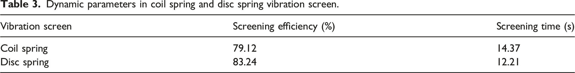
It can be seen from Table 3 that the screening efficiency of disc spring vibration screen is 4.12% higher than that of coil spring vibration screen, and the screening time is shortened by 2.16 s. The screening efficiency and time results of DEM verify the rationality and reliability of the vibration screen trajectory analysis. Thus, the superiority of the disc spring vibration screen is proved again.
Mechanical, fatigue, and life performance analysis
The amplitude and amplification factor of the coil spring and disc spring vibration screen under the same working frequency and exciting force are shown in Figure 13. It can be observed that the amplitude of disc spring vibration screen in the vertical and horizontal directions is much larger than that of the coil spring vibration screen, and the amplification factors of the two vibration screens are consistent with the amplitudes.
42
Therefore, the disc spring vibration screen has better dynamic performance compared with the coil spring vibration screen. Dynamic characteristics of coil spring and disc spring vibration screen.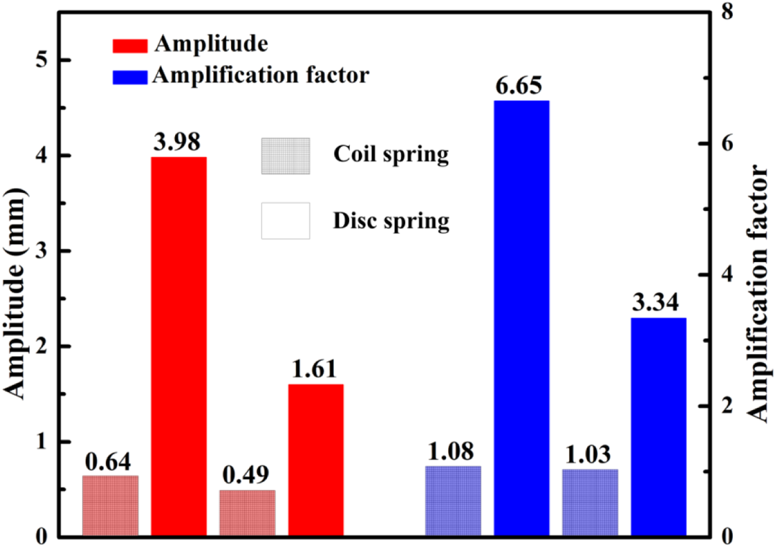
Dynamic parameters in coil spring and disc spring vibration screen.
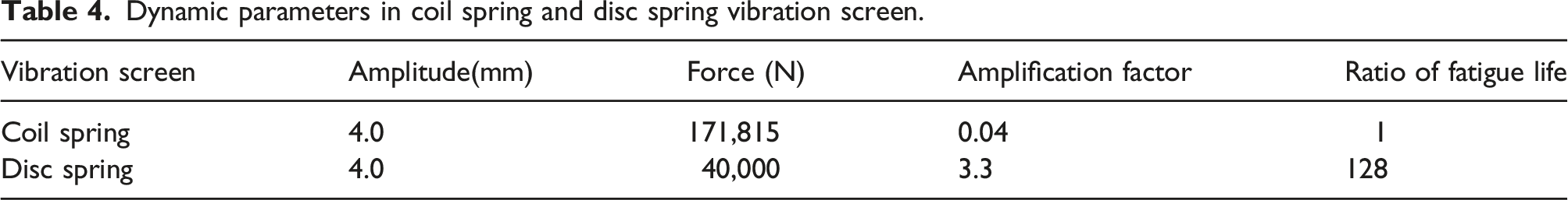
The rotating spindle bearing of vibration screen is easy to damage under the effect of alternate forces.43,44 The replacement and maintenance process of bearings is time-consuming and labor-intensive, which seriously affects the progress of wet sand and gravel production and brings huge economic losses to the enterprise.
Fortunately, the required exciting force is significantly reduced under the same amplitude in disc spring vibration screen, which greatly prolong the fatigue life of the spindle bearing. According to the calculation of bearing life equation (8),
45
the fatigue life of the spindle bearing of the disc spring vibration is 128 times that of the coil spring vibration screen under the same amplitude
Due to the special structural of disc spring, the vertical rigidity of the disc spring is much higher than that of ordinary coil spring. Meanwhile, the processing of coil spring with large vertical rigidity is extremely difficult and costly. Moreover, the coil spring with large vertical rigidity increases the assembly difficulty. Furthermore, the vertical rigidity can be more easily adjusted through combination of disc springs. Therefore, the disc spring does demonstrate the superiorities in increasing bearing life of vibration screen.
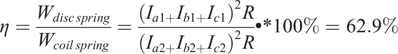
Besides long service life and high reliability, energy consumption is another important evaluation indicator in vibration screen.46,47The exciting force is generated by the rotation of the eccentric block driven by motor. Therefore, the energy consumption of the vibration screen mainly depends on the energy consumption of the motor. The simple calculation equation of energy consumption of three-phase motor
48
is shown in equation (9)
W is the total energy consumption of three-phase motor. I a , I b , I c are the current of each phase line, and R is the corresponding resistance.
Measured value of each phase current in coil spring and disc spring vibration screen.
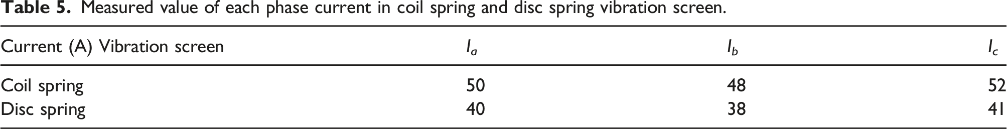
It can be clearly seen that the energy loss of disc spring vibration screen is only 62.9% that of coil spring vibration screen, which greatly reduces the production cost and meets the needs of environment protection.
Conclusion
The vibration screen with disc spring system as elastic support component is designed to reduce the working load, ensure mechanical linearity, and increase the amplitude in this work. The dynamic characteristics, screening mode and fatigue and life performance of disc spring vibration screen has been analyzed by finite element and discrete element method. The following conclusions can be drawn from the previous discussions:
The previous four natural frequencies and mode shapes of the disc spring vibration screen are obtained by simulation and experiment. It is found that the model moves up and down in vertical direction at first natural frequency (17.361 Hz), which is consistent with the moving direction of the vibration screen.
Then, the amplitude simulation and test of disc spring vibration screen are carried out, and the results show that the working amplitude is stable under the working frequency. The maximum amplitude in vertical direction is 8.8 while that in horizontal direction is 3.2 mm. The above amplitudes can fully meet the needs of industrial production.
In addition, the motion trajectories on different positions of the vibration screen box are obtained with above amplitudes. It can be found that the elliptical trajectories on the screen box gradually rotate clockwise from the feeding port to the discharging outlet, which indicates that the horizontal displacement component of the motion trajectory increases gradually as the wet particles move along the screen surface. By further comparing the screening efficiency and screening time under the trajectories of the coil spring and disc spring vibration screen, the higher screening efficiency and shorter screening time are obtained with disc spring vibration screen.
Moreover, the dynamic analysis suggests that the exciting force required by the disc spring vibration screen is 23.2% that of the coil spring vibration screen under the same amplitude while the power loss of the disc spring vibration screen is only 62.9% that of the coil spring vibration screen. Furthermore, by comparing the fatigue life of spindle bearing between the coil spring and disc spring vibration screen, it can be found that the fatigue life of the spindle bearing in disc spring vibration screen is 128 times that of the coil spring vibration screen.
The above results show that the disc spring vibration screen has stronger screening efficiency, greater screening capacity, better mechanical properties, higher reliability, and lower energy consumption than the coil spring vibration screen. The invention of the disc spring vibrating screen provides guidance and reference for the subsequent design and application of vibration screen.
Footnotes
Author contribution
Jiacheng Zhou and Libin Zhang designed and conducted the simulation and experiment, and wrote the first draft of the article. Longchao Cao conducted experimental analyses. Jiacheng Zhou and Junjie Tang contributed to the systematic review of the literature, and data retrieval and extraction. Libin Zhang and Kuanmin Mao conceived and analyzed the data and drafted the article. Longchao Cao and Lianqing Yu funded this research and provided all the experimental devices.
Declaration of conflicting interests
The author(s) declared no potential conflicts of interest with respect to the research, authorship, and/or publication of this article.
Funding
The author(s) disclosed receipt of the following financial support for the research, authorship, and/or publication of this article: This work was supported by the National Natural Science Foundation of China (NSFC) under grant number 62204178 and 52105446, the Natural Science Foundation of Hubei Province under grant number 2022CFB995, Guidance Project of Science and Technology Research Program of Hubei Provincial Department of Education under grant number B2021107, and Knowledge Innovation Program of Wuhan-Shuguang Project under grant number 2022010801020252.