
Abstract
In this study, a finite element model of a pressure cartridge-type pin puller is used to simulate the actuation process and predict the actuation shock using the deflagration equation of state and the fluid-structure coupling algorithm of the MSC/Dytran. The established model is validated by comparing the simulation results with the experimental results for pressure and actuation shocks. Based on the established finite element model, the contribution of the four shock sources to the actuation shock is quantitatively decoupled by changing the state of the pin puller. The results demonstrate that the maximum shock caused by the piston impact was 7454.33 G in the analysis frequency range of 500 Hz–10 kHz. The piston impact was the primary contributor to the actuation shock, accounting for approximately 80.80%. The contribution of the shock caused by payload release was approximately 18.56%. However, the total contributions of the shock generated by the pyrotechnic charge combustion and piston cutting off the shear pin were less than 1%. The conclusions of this study can provide a reference for the structural and shock-reduction design of pressure cartridge-type pyrotechnic separation devices.
Keywords
Introduction
Pressure cartridge-type pin pullers are typical low-shock pyrotechnic separation devices that are widely used for locking and releasing spacecraft structures, 1 such as solar arrays and antennae. The pyrotechnic charges in the pressure cartridge burn to produce high-pressure gas, which pushes the piston back and subsequently releases the payload. The combustion of the pyrotechnic charges, expansion of the chamber and retraction of the piston are coupled in a few milliseconds of actuation time. These complex internal actuation processes are challenging to measure and observe experimentally. On the other hand, the pyrotechnic shock (pyroshock) generated by these actuation processes may cause the failure of microelectromechanical systems on board the spacecraft,2,3 leading to the failure of the entire space mission. 4 Therefore, it is necessary to efficiently and accurately simulate the combustion of pyrotechnic charges and the motion of the moving mechanism using the explicit dynamic finite element method to obtain the stress changes in the moving mechanisms and actuation shocks during the actuation process. The results obtained from simulations can not only guide the structural design of pressure cartridge-type pyrotechnic devices but also provide an accurate source of shock input for predicting the pyroshock environments of complex spacecraft structures. 5 In addition, analysing the time and frequency characteristics of different shock sources and quantifying the contribution of each shock source to the actuation shock of the pin puller can help in taking effective shock-reduction measures.
Theoretical modelling6–11 and numerical simulation12–15 are the most common methods used to study the actuation processes of pyrotechnic separation devices. Theoretical modelling develops mathematical models to predict the actuation processes of pin pullers based on experimental results.6–8 Mathematical models can simulate the pressure generated by the combustion of pyrotechnic charges, and thus obtain the velocity and displacement of the internal moving mechanism. However, mathematical models are zero-dimensional, assuming that thermodynamic parameters are only a function of time. Therefore, they can neither visualise the flow field distribution of the combustion products nor predict pyroshock. Numerical simulations have the advantages of low cost and reliable results. Commercial hydrocodes such as ANSYS/Autodyn, ANSYS/Ls-Dyna and MSC/Dytran have been widely used to simulate the separation processes of pyrotechnic separation devices and predict the separation shock. The Jones–Wilkins–Lee equation of state (EOSJWL) for explosives is often used to simulate the combustion of pyrotechnic charges in a pressure cartridge based on the principle of energy equivalence.12–15 However, the JWL equation of state can only simulate instantaneous detonation, which generates high pressure with an oscillation step. The deflagration equation of state (EOSDEF) expressed in the MSC/Dytran can simulate both the reaction rate and pressure generated by the subsonic combustion of pyrotechnic charges. 16 Zhao et al. 17 used the EOSDEF to simulate the pressure–time profiles of two pyrotechnic charges (C/KNO3 and Al/KClO4) burning in a closed bomb. The relative error between the simulations and experimental results is less than 10%.
Time splitting is the most common method15,18,19 for decoupling the pyrotechnic shock sources. To calculate the contribution of different types of shock sources to the shock of the actuation process, the shock acceleration curves obtained from numerical simulations 15 and tests18,19 were split according to critical temporal moments in the actuation process, such as ignition/detonation and mechanism movement. Kozmic et al. 18 decoupled the experimental acceleration–time histories of a pyrotechnic separation nut. They found that the bolt release mechanism and internal piston impact determined the high-frequency and low-frequency portions of the separation shock, respectively. Because different shock sources are assumed to be independent, the time-splitting method ignores the coupling of the various shock sources within a few milliseconds of the actuation time. To address this problem, some researchers have modelled different pyroshock-generating mechanisms separately to identify the characteristics of various pyrotechnic shock sources. Xiong et al. 20 used ANSYS/Ls-Dyna to construct individual finite element models of a separation nut. They found that the contributions of the preload release and internal mechanism collision to the separation shock were 63% and 5%, respectively. However, there has been little discussion regarding the shock generation mechanism and shock decoupling of pin pullers. Standards related to pyroshock21–23 only provide the shock response spectrum (SRS) of pin pullers and attenuation rules with respect to distance.
This study simulates the actuation process and output shock of the pin puller based on the deflagration equation of state 16 and the fluid-structure coupling algorithm developed into the MSC/Dytran. The accuracy of this model was validated by comparing the results of the simulations and the multiparameter test system. Based on the established finite element model, the state of the pin puller is changed to decouple the contribution of pyrotechnic charge combustion, payload release, piston impact and piston cutting off the shear pin to the actuation shock. The fluid-structure coupling simulation process and shock source decoupling method proposed in this study can be applied to the structural and shock-reduction design of pressure cartridge-type pyrotechnic separation devices.
Pin puller and multiparameter test system
Structure and auction process of pin puller
The pin puller considered in this study comprises mainly igniters, housing, piston, shear pin and cushion, as shown in Figure 1. The pin puller installed two igniters to ensure reliable actuation. The igniter used lead styphnate (10 mg) as the primary charge. The main charge was aluminium-potassium perchlorate (APP), with a charge of 75 mg. The design value of the payload was 10 kN, and the design stroke of the piston was 12 mm. Schematic of pin puller.
The actuation process of the pin puller is shown in Figure 2, and can be divided into five stages according to the four critical states. First, the APP starts to burn after ignition, producing hot gas. The hot gas flowed through the orifice and into the expansion chamber, pushing the piston to shear the shear pin. Subsequently, the piston cut off the shear pin and quickly retracted to 11 mm to release the payload. In Stage 3, the piston continues to retract and thereafter impacts the cushion at the end of its stroke. In Stage 4, the piston rebounds from the cushion. Finally, the piston stopped moving under the pressure. The primary mechanisms generating the output shock of the pin puller include pyrotechnic charge combustion, piston cutting off the shear pin, payload release and piston end of stroke impact. Sequence of the actuation process.
Multiparameter synchronous test system
A multiparameter synchronous test system was constructed to test the output shock of the pin puller and pressure profile in the chamber. The principle and test setups are shown in Figures 3 and 4, respectively. A 60 cm × 60 cm × 1 cm aluminium plate was suspended with elastic ropes to exclude the effect of gravity on the relative velocity when releasing the payload. The pin puller was mounted at the centre of the shock response plate through a steel fixture, and fitted with an igniter on one side and a CY-YD-205 piezoelectric pressure sensor to monitor the pressure changes in the chamber. The accelerations in the main direction of the shock (Z-axis as shown in Figure 4) were measured using a PCB 350B01 accelerometer at 15 cm from the centre of the shock response plate. The payload was applied to the piston by using bolts and the force blocks. A CL-YD-3103 force sensor placed between the force block and nut was used to monitor the application process of the payload. For the measurements, the sampling rate of the data acquisition system was set as 1 MHz to reduce aliasing. The transducer specifications are listed in Table 1. The tests were performed using a Kistler-5015A charge amplifier and a DEWE-4010 data acquisition system (DAQ) with a maximum sampling rate of 2 MHz for all eight channels. The analog-to-digital converter for the DAQ employs a 16 Bit resolution. The specifications of transducers, signal conditioners and DAQ meet the requirements of the pyroshock test.
22
The ignition controller sent an ignition signal to the igniter. Simultaneously, the DAQ receives the trigger signal and starts to work. The accelerometer recorded the acceleration signals, and the pressure transducer recorded the pressure profiles in the chamber, which were thereafter conditioned and transmitted to the DAQ. Schematic of the multiparameter synchronous test system for the pin puller. Test site of the multiparameter synchronous test system. Specifications of the transducers.
21
Numerical simulation model
Simulation process
Figure 5 shows the simulation process performed in three steps. The first step is to develop a simplified geometric model of the multiparameter synchronous test system. In addition, the material parameters of the solid structures were obtained from literature. The material parameters of the main charge were obtained using the general thermodynamics code REAL
24
and tests. Second, a finite element model was established using the pre-processing software MSC/Patran.
16
Finally, the finite element model was computed using MSC/Dytran.
16
The combustion process of the main charge is calculated in the Eulerian domain. Subsequently, the general coupling method computes the fluid-structure interaction between the Lagrangian and Eulerian meshes, and transfers the pressure and displacement parameters. The output shock of the pin puller is calculated using an explicit integration method. Numerical simulation process.
Finite element model
According to the structure of the pin puller and multiparameter synchronous test system, a finite element model comprising a pin puller, fixture and shock response plate was developed, as shown in Figure 6. An integrated model of the igniter, end cap and housing of the pin puller was established to simplify the model. The pyrotechnic charges were simplified to one layer of APP. A 1/2 model was developed based on the symmetry of the structure. The fluid domain was divided into Eulerian meshes with sizes of 0.5 mm, and the total number of units was 69,120. The pin puller, fixture and shock response plate were divided into Lagrangian meshes, with sizes ranging from 1.0 to 2.0 mm, and the total number of units was 534,749. An acceleration monitoring point was set 15 cm from the centre of the shock response plate to obtain the shock acceleration in the Z-direction. A pressure monitoring point was set in the Eulerian domain to monitor the pressure inside the chamber in which the pressure sensor was installed. The finite element model uses an international unit system. Finite element model.
The pin puller is bolted to the fixture. To simplify the calculation, the contact between the pin puller and fixture was defined as a rigid connection. The fixture and shock response plate were connected through shared nodes. The interaction among all other Lagrangian components was modelled using contact surfaces, with a friction coefficient of 0.1. Free boundary conditions were applied to the shock response plate. A payload was applied to the piston using a bolt.
Material models
Combustion model
The EOSDEF in MSC/Dytran can simulate the pressure and reaction rate of pyrotechnic charge combustion and obtain the energy parameters. Based on the interior ballistic theory, the EOSDEF makes the following assumptions to describe the combustion process of pyrotechnic charges: 1. All pyrotechnic charge grains start to burn at 0 ms, and the ignition delay time is ignored. 2. The exposed burning surfaces of all pyrotechnic charge grains burn simultaneously and move inward in the direction perpendicular to itself. 3. All pyrotechnic charge grains are of the same size and configuration. 4. The components of the combustion products remain unchanged.
25
5. Heat losses during the combustion process are not considered.
The burning rate of the main charge satisfies Saint–Robert law,
26
as expressed in equation (1)
The time derivative of the burn fraction of the main charge is determined by the shape and the burning rate of the main charge, as expressed in equation (2)

In equation (3), X and Y are two parameters of the form function.

Material parameters of main charge APP.
Structure material
Material parameters of solid structures.
Numerical simulation results
Actuation process
The pressure contours in the pin puller during the actuation process are shown in Figure 7. Figure 8 shows the time histories of the pressure at the pressure monitoring point, displacement of the piston and burn fraction of the APP. In Stage 1, the APP started to burn at 0 ms, forming a high-pressure area in the combustion chamber. It can be seen from Figure 7(a) that the pressure inside the expansion chamber rises rapidly at 0.05 ms owing to the high-pressure gas flowing into the expansion chamber through the orifice. Next, the piston is gradually accelerated by the pressure and starts to shear the pin at 0.20 ms. The APP stops burning at tB (0.25 ms), as shown in Figure 8. The pressure reaches a peak of 26.55 MPa at 0.20 ms. The movement of the piston increases the volume of the expansion chamber. Thus, the time when the pressure peak occurs is earlier than that for the end of combustion. The shear pin fails at point A in Figure 8, and Stage 2 begins at approximately 0.45 ms. Pressure nephograms at critical moments during the actuation process. (a) t = 0.05 ms (b) t = 0.20 ms (c) t = 0.45 ms (d) t = 0.70 ms (e) t = 0.85 ms (f) t = 1.40 ms. Time–pressure history of the chamber, time–displacement history of the piston and burn fraction.
During Stage 2, the piston was rapidly accelerated by the pressure, causing the chamber volume to increase, and accordingly, the pressure decreased. At the beginning of Stage 3, the piston moved to the unlock stroke (11 mm) and detached from the fixture at point B (0.70 ms), as shown in Figure 8. At point C in Figure 8, the piston retracts to the maximum stroke (12 mm) and impacts the cushion at 0.82 ms. Simultaneously, the pressure reaches a minimum value of 10.84 MPa. Subsequently, Stage 4 begins, and the piston rebounds from the cushion. The pressure rises again and reaches the secondary peak of 14.23 MPa at 0.96 ms. Subsequently, the pressure oscillates. After 1.40 ms, the piston stops moving under pressure, as shown in Figure 8. The actuation time of the pin puller is less than 2 ms. The finite element simulation process proposed in this study can simulate the coupling process of combustion of the main charge, flow of combustion products, and separation process of piston motion, unlocking and collision.
Comparison of numerical simulation results and experiments
A simulation was performed using EOSJWL to verify the accuracy of the results from the finite element model using EOSDEF. Based on energy equivalence, the primary charge (10 mg) and APP (75 mg) were simplified to a 50 mg charge of TNT with a loading density of 1.63 g/cm3. The detonation products of TNT were described using the JWL equation of state, and the material parameters were obtained from the literature.
30
Figure 9 shows a comparison of the pressure profiles obtained from the simulations and tests. In the tests, the pressure increased rapidly after ignition at t1 (0.45 ms). The first pressure peak is 24.98 MPa at t2 (0.70 ms). Subsequently, the pressure decreases because the chamber volume increases owing to piston retraction, reaching a minimum value of 9.97 MPa at t3 (1.16 ms). At this point, the piston impacts the cushion and rebounds, causing the chamber volume to decrease. The pressure increases and reaches the second peak of 13.44 MPa at t4 (1.38 ms), and subsequently, pressure decreases due to the heat losses. Comparison of pressure–time histories from experiment and simulations.
Comparison of pressure results obtained by different models and experiments.
An eighth-order Butterworth digital filter filters the acceleration–time histories from simulations and experiments to eliminate aliasing and low-frequency drifts, with upper and lower cut off frequencies set as 100 Hz and 30 kHz, respectively. SRS was calculated using an improved recursive digital filtering method.
31
The frequency range was 100 Hz–10 kHz, the frequency spacing was set as 1/12 octave and damping ratio ξ is set as 0.05. Figure 10 compares the acceleration–time histories and the corresponding SRS from the simulations and tests. The difference between the simulation and experimental results is mainly attributed to some simplifications made during the modelling process, resulting in a change in the stiffness and mass distribution of the entire system. The acceleration–time history from the model using EOSJWL was greater than that of the experimental result, as shown in Figure 10(a). The shock generated by the ignition event reached the monitoring point earlier than that during the test, and the acceleration–time history from the model using the EOSDEF was of the same order of magnitude as the experimental result and had similar oscillatory characteristics. In the frequency domain, most of the experimental SRS was surrounded by ± 6 dB of the simulated SRS, as shown in Figure 10(b). The average difference between the simulated and the experimental SRS is 3.91 dB and 2.99 dB over the entire frequency band for the two models using the EOSJWL and EOSDEF, respectively. Overall, the finite element model using EOSEDF predicts more accurate pressure and output shock results than the model using EOSJWL. The non-linear finite element simulation process proposed in this study can be used for the accurate prediction of pyrotechnic shock sources. Comparison between numerical simulation and measured shock. (a) Acceleration time history (b) Shock response spectrum.
As shown in Figure 10(b), the actuation shock of the pin puller was distributed over a wide frequency range and had a high amplitude. Eriksson 32 found that the signal-to-noise ratio of the experimental SRS below 500 Hz is extremely low, and the SRS will thereafter be useless below 500 Hz. In addition, pyroshocks generate material stress waves that may excite microelectronic chips to respond to high frequencies, causing damage to electronic devices. 22 The upper frequency of SRS is typically 10 kHz when evaluating the damage potential of a pyroshock. Therefore, a frequency range of 500Hz–10 kHz was selected for this study to analyse the characteristics of various shock sources.
Shock decoupling analysis
Finite element model for decoupling shock sources
The actuation time of the pin puller was less than 2 ms, and different pyroshock-generating mechanisms were coupled in the time domain. Therefore, decoupling shock sources using the time-splitting method is difficult. Several finite element models of the pin puller in different states have been developed to decouple the actuation shock, as shown in Figure 11. Different finite element models for decoupling shock source. (a) Model 1 (b) Model 2 (c) Model 3 (d) Model 4.
Shock sources contained in different finite element models.
Characteristics of shocks of different models
Figure 12 compares the acceleration–time histories, and the corresponding SRS and ESD from the different finite element models. Because the piston does not impact the cushion, the acceleration–time histories of Models 1 and 2, depicted in Figure 12(a), are nearly identical until 1 ms. It can be seen from Figure 12(b) that the shock of Model 1 is significantly greater than that of other models. The peak SRS was 9093.7 G at 8063.5 Hz. The shock of Model 2 is slightly smaller than that of Model 1, with a peak SRS of 4560.76 G at 5381.7 Hz. The shocks of Models 3 and 4 are much smaller than those of Models 1 and 2, with a maximum value of SRS less than 900 G. For Model 4, APP combustion is the only source of pyroshock. The shock energy is concentrated in the far field (<3 kHz). The maximum amplitude of the ESD is 513.4 g2 s/Hz at 1098.9 Hz, as shown in Figure 12(c). Shock from different finite element models. (a) Acceleration (b) Shock response spectrum (c) Energy spectral density.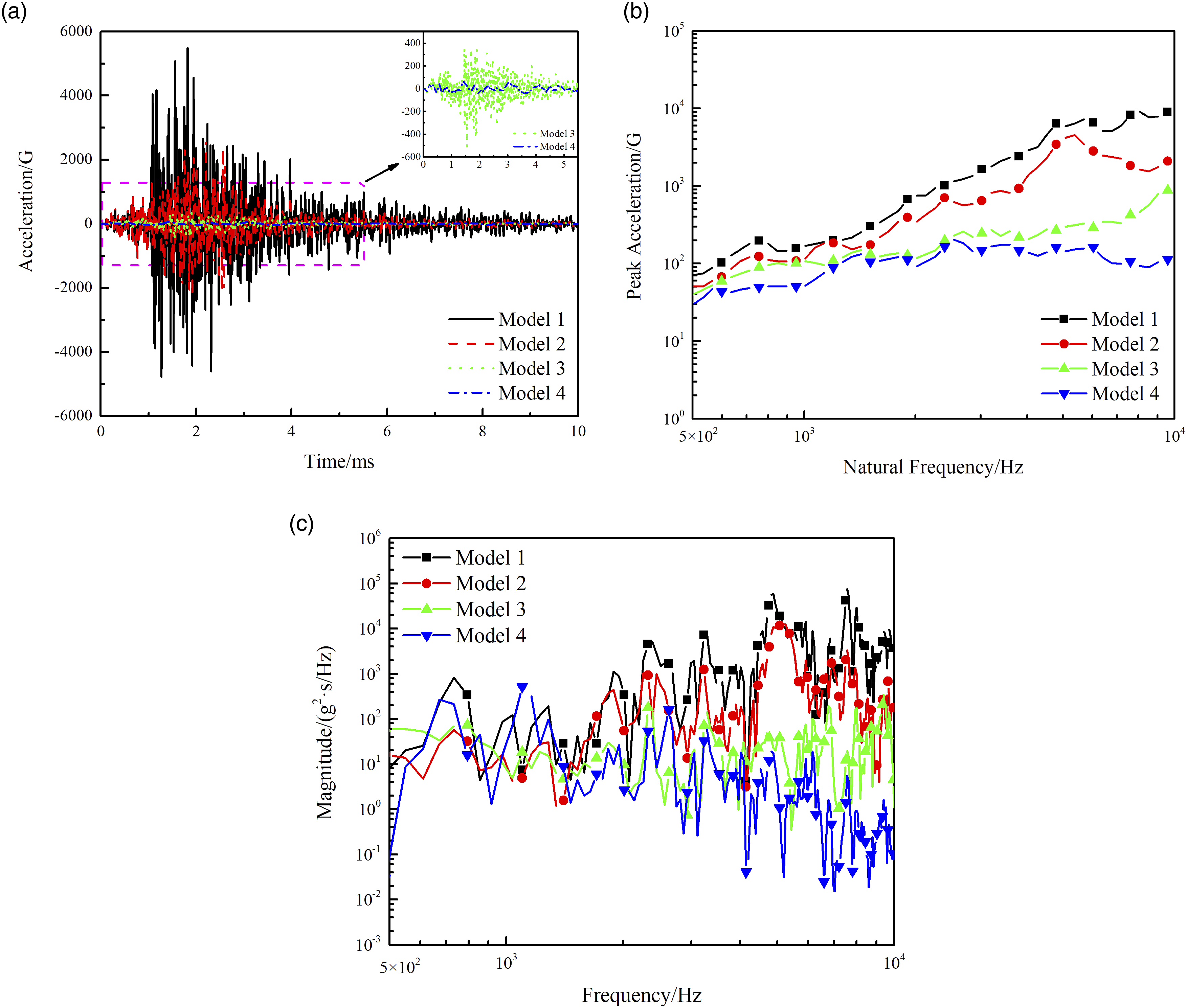
Decoupling the SRS of different shock sources
According to the shock sources contained in the different finite element models listed in Table 5, the SRS generated by the various shock sources can be calculated using equations (5)–(8).


The SRSs of the different shock sources were calculated, as shown in Figure 13(a). Figure 13(b) shows the relative values of the SRS, which is the ratio of the SRS of each shock source divided by the SRS of Model 1 at each frequency. From the results in Figure 13(b), the shock generated from the combustion of APP contributes significantly to the far-field pyroshock (<3 kHz). In addition, the piston cutting off the shear pin is also the primary contributor to the far-field pyroshock. Because the shear pin is only 2.5 mm in diameter and made of low-strength 5A03 aluminium alloy, the fracture process of the shear pin was a plastic deformation of the material. The shock generated by the piston cutting off the shear pin is less than 800 G over the whole frequency domain, as shown in Figure 13(a). The shock generated by the payload release contributes significantly to mid-field pyroshock (3–10 kHz), and the maximum value of the SRS is 4247.3 G at 5381.7 Hz. The piston impacting the cushion features a metal-to-metal impact and plastic deformation of the materials. Therefore, the shock induced by the piston impacting the cushion is the primary contributor to the pyroshock in the overall frequency domain, and the maximum value of SRS is 7454.3 G at 8063.5 Hz. Calculated SRS and relative value of SRS of different shock sources. (a) Calculated SRS (b) Relative SRS values. SRS: shock response spectrum.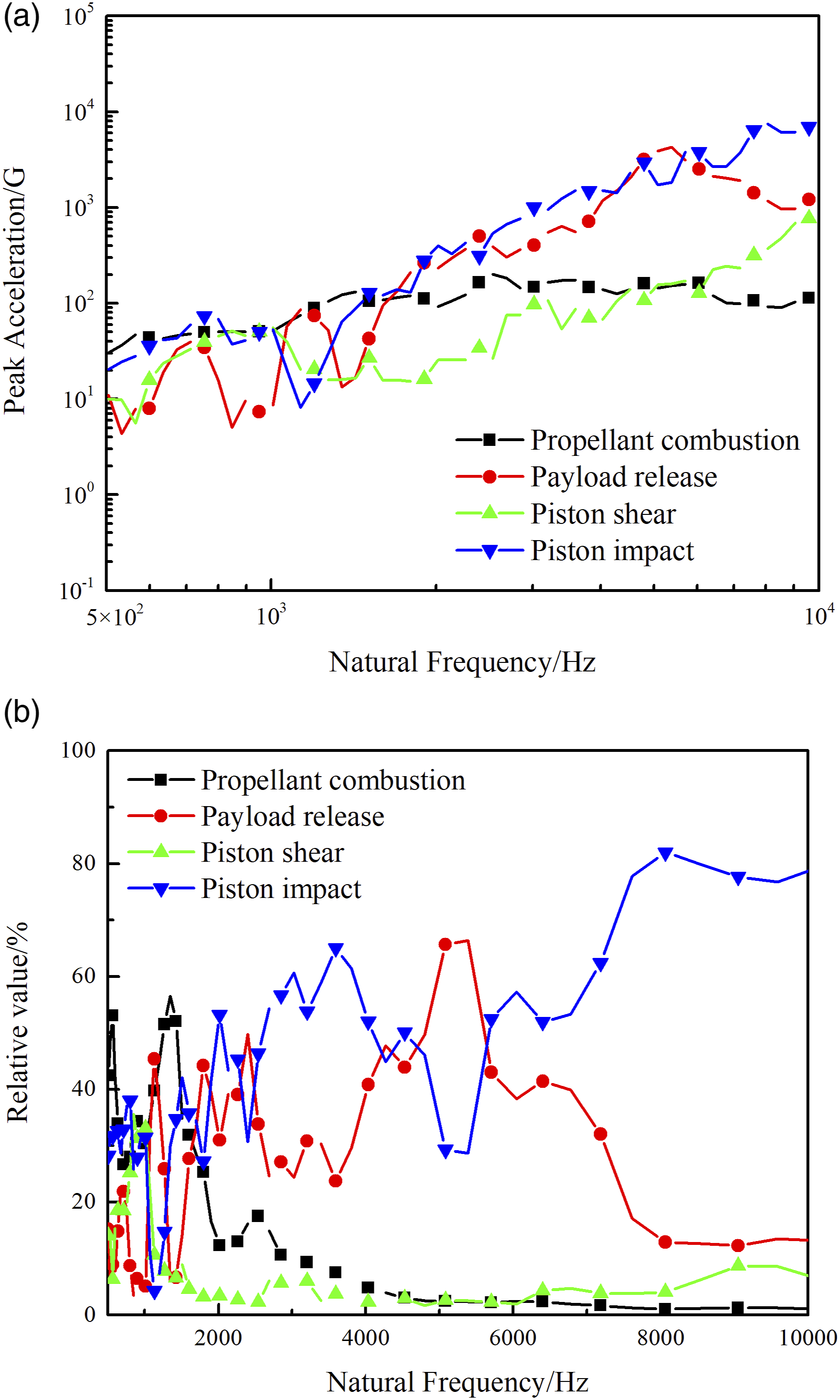
Contribution of different shock sources
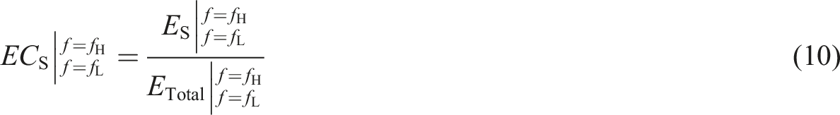
The related standards for pyroshocks propose that the energy of the shock sources can be calculated from the ESD. In addition, source energy scaling has been used to predict pyroshock environment.21,22 In this study, the ESD was used to calculate the contribution of various shock sources to the actuation shock of the pin puller. The shock energy can be obtained by integrating the ESD from different finite element models, as expressed in equation (9)
Shock contributions from various shock sources.
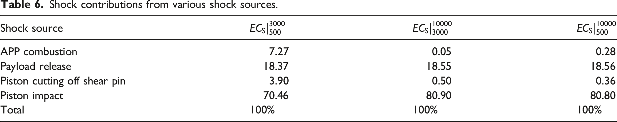
From Table 6, because the direction of transmission of the combustion wave is perpendicular to the main direction of the shock, the APP combustion is not a significant contributor, accounting for 0.28% of the entire frequency domain. The piston cutting off the shear pin was also not a major contributor, accounting for 0.36% of the total frequency range. In addition, the shock contributions of these two shock sources to the far-field pyroshock were more significant than those of the mid-field pyroshock. The shock contributions of the payload release to the far-field and the mid-field pyroshocks were approximately equal. The shock contribution caused by the payload release did not exceed 19% over the entire frequency range. The actuation shock of the pin puller was primarily driven by the piston impacting the cushion. The shock contribution of the piston impacting the cushion was 80.80% over the entire frequency range. These results indicate that the design to reduce the shock of the pin puller should focus on the shock induced by the piston end of the travel impact. One method is reducing the rising rate of the gas pressure and maximum pressure 19 to decrease the velocity of the piston at the end of the piston stroke. On the other hand, the structure and material of the cushion can be optimised to absorb more energy generated by the piston impact.33–35
Conclusion
This study proposes a reference numerical simulation method to predict the separation process and shock of pressure cartridge-type separation devices. A finite element model for predicting the actuation process of the pin puller and output shock was established based on a multiparameter synchronous test system and MSC/Dytran software. The coupling process between the flow of combustion products and piston motion was simulated, the generation mechanism and time–frequency characteristics of the actuation shock were analysed, and the sources of the actuation shock were quantitatively decoupled. The results can guide the structural design and selection of shock-reduction methods for pressure cartridge-type pyrotechnic separations. The results demonstrate that the established finite element model using the EOSDEF can simulate APP combustion and movement of the internal moving components. The pressure and actuation shock predicted by this finite element model agreed with the experimental results. However, the model using EOSJWL overestimated the pressure and actuation shock. The SRSs of the different shock sources were calculated using finite element models for different states. In the analysis frequency range of 500 Hz–10 kHz, the peak SRS for the payload release and piston impacting the cushion is greater than 4000 G. The SRSs for the APP combustion and piston cutting off the shear pin were less than 800 G. The contributions of APP combustion, payload release, piston cutting off the shear pin and piston impact to the actuation shock are quantitatively decoupled. The piston impacting the cushion was the main contributor to the actuation shock. This shock accounts for 80.80% of the total actuation shock. The shock induced by payload release accounts for 18.56%. The contribution of piston cutting off the shear pin was minor, accounting for 0.36%. The contribution of APP combustion is minimal, accounting for 0.28%.
Footnotes
Acknowledgements
Declaration of conflicting interests
The author(s) declared no potential conflicts of interest with respect to the research, authorship, and/or publication of this article.
Funding
The author(s) received no financial support for the research, authorship, and/or publication of this article.