
Abstract
Muffler with circular section and inner symmetric acoustical elements has been habitually used in industry. In order to improve the acoustical performance, an advanced eccentric muffler having ellipse cross-section, multiple chambers, and multi-segment perforated/non-perforated tubes is presented. Concerning about high order wave effect to the muffler, a finite element method (FEM) run on COMSOL package is adopted. In addition, the influence of sound transmission loss with respect to various geometric parameters has been explored. In order to simplify the optimization process, a simplified objective function established by an Artificial Neural Network (ANN) and FEM has been implemented and connected to a Genetic Algorithm (GA). Two case studies of muffler optimization for two kinds of design parameter sets (one of Lin and Lout and the other of Lin1 and Lout 1) are introduced. Two targeted frequencies (1000 Hz and 2500 Hz) are selected and applied in the two cases’ muffler optimization. Simulated results reveal that the acoustical influence relating to various geometric parameters is huge. The sound attenuation will increase in the low frequency region if the curvature ratio δ (ratio of long axis to short axis in ellipse) or the X (horizontal length of the muffler’s body) increases. Consequently, the study demonstrates a methodology in the optimization of a four-chamber ellipse and eccentric muffler internally inserted with multi-segment perforated/non-perforated tubes.
Introduction
Muffler with circular section has been habitually used in industry.1,2 Based on a fluid dynamic theory, Munjal 3 estimated muffler’s noise reduction using a four-pole transfer matrix in 1957. Sullivan and Crocker4,5 proposed coupled equations for the outer and the inner tubes of a perforated muffler. The acoustical effect discussed above ignores the higher order wave. To conquer this drawback, Ih and Lee6,7 presented a theoretical method to forecast the acoustical performance of a circular-sectioned and expansion muffler. Considering the flow effect to the muffler, Chu et al. 8 analyzed the effects of airflow on a reactive muffler. Nevertheless, the research of muffler having ellipse cross-section is rarely addressed.
In order to realize the acoustical behavior of a muffler having an ellipse cross-section, Denia started the ellipse muffler analysis using the Helmholtz equation in 2001. 9 But, it is constrained in one dimension only. Mimani and Munjal, 10 in 2018, proposed a 3-D acoustic analysis of elliptical chamber mufflers which have an end inlet and a side outlet using an impedance matrix approach. Mimani and Munjal, 11 also investigated the acoustical performance for an elliptical end and expansion-chamber muffler using the transverse plane-wave theory. Considering plane wave model, Siano et al. analyzed acoustic performance and related fluid-dynamic for an automotive muffler. 12 Yet, the acoustical effect of a higher order wave was neglected. In order to obtain more accurate prediction, Mimani and Kirby 13 assessed acoustical performance by using a numerical mode matching method of Kirby.14–16 However, the acoustical performance mentioned above is confined in the region of cut-off frequency below. Besides, there is no discussion relating to muffler optimization which is necessary in solving engineering problem of space-constrained issue and cost concern. 17 Considering a high-order-mode effect in mufflers, Chiu and Chang et al. implemented muffler optimization within a space-constrained situation using eigen function;18–21 however, the discussion of straight/reverse mufflers’ cross section were restricted on rectangular and circular shapes only.
Even though the one-chamber ellipse mufflers with a straight perforated tube mentioned above is found to have an acoustical improvement in low frequencies, it is still insufficient for noise abatement in wide frequency region. Therefore, a multi-chamber and eccentric muffler equipped with ellipse cross-section and internally connected with multi-segment perforated/non-perforated tubes is proposed. For the muffler having complicated mechanism, it is hard to assess acoustical field using a theoretical analysis;22–26 therefore, a FEM (Finite Element Method) simulation is then considered to be used in the acoustical simulation.
Considering a high order wave effect in muffler, the ellipse muffler is acoustically analyzed by using a finite element method (FEM) run on COMSOL package. Regarding the optimization using the FEM, it is time-consuming in model establishing and computer calculation. 27 Chang et al. 28 thus established a simplified objective function used in the muffler optimization via the neural network in conjunction with a genetic algorithm in 2009. Later, Chiu, 29 in 2014, optimally assessed rectangular side inlet/outlet plenums internally hybridized with two crossed baffles using Artificial Neural Network (ANN) and a genetic algorithm. Therefore, to facilitate the optimization process, a simplified objective function established by ANN and FEM will be adopted and connected to a Genetic Algorithm (GA). Besides, two case studies of muffler optimization by using two kinds of design parameter sets (one of the Lin and Lout and the other of the Lin1 and Lout 1) are introduced. To protect people’s hearing health, two sensitive frequencies of 1000 Hz and 2500 Hz are chosen as the targeted frequencies used in the muffler optimization.
Mathematical model of the FEM (Run on the COMSOL Package)
As indicated in Figure 1, an ellipse muffler internally inserted with baffles, perforated tubes and an eccentric outlet has been introduced. The boundary condition for the acoustical field of a solid boundary used in the acoustical model with the COMSOL package is An ellipse muffler internally inserted with baffles and perforated tube and an eccentric inlet.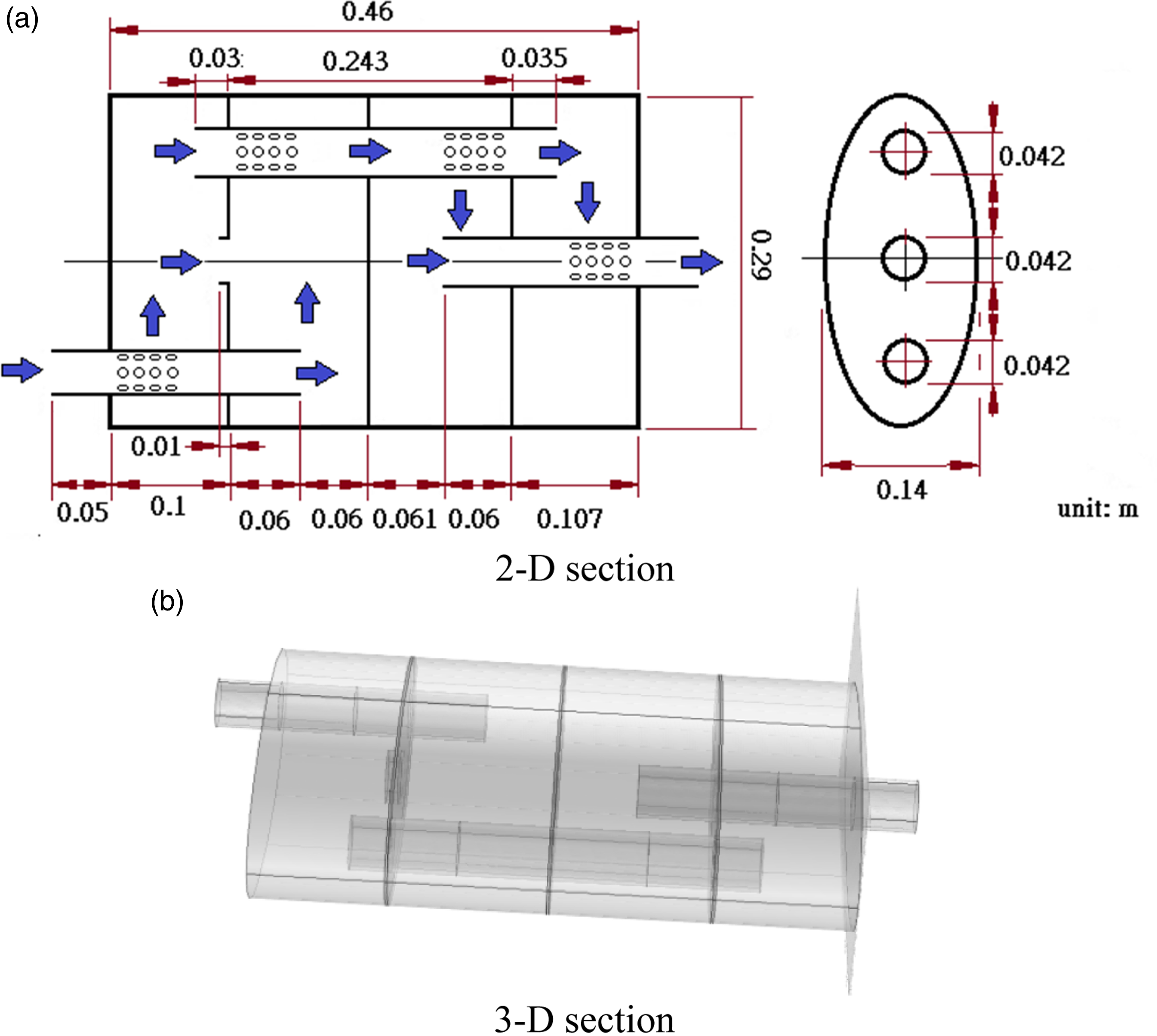

The boundary condition of perforated tube (a solid boundary) used in the COMSOL model is


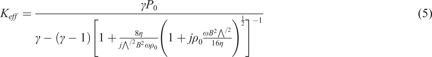
The Johnson-Champoux-Allard model used for analyzing acoustical behavior of a porous acoustical wool yields

The bulk factor (
The governing equation of sound wave propagating along the muffler yields


The TL (Transmission Loss) for muffler is

Model check
Before muffler’s shape optimization is performed, an accuracy verification of FEM model (run on COMSOL) is required. As seen in Figure 2, the simulated TL of a muffle equipped with perforated tubes is confirmed by an experimental data.
30
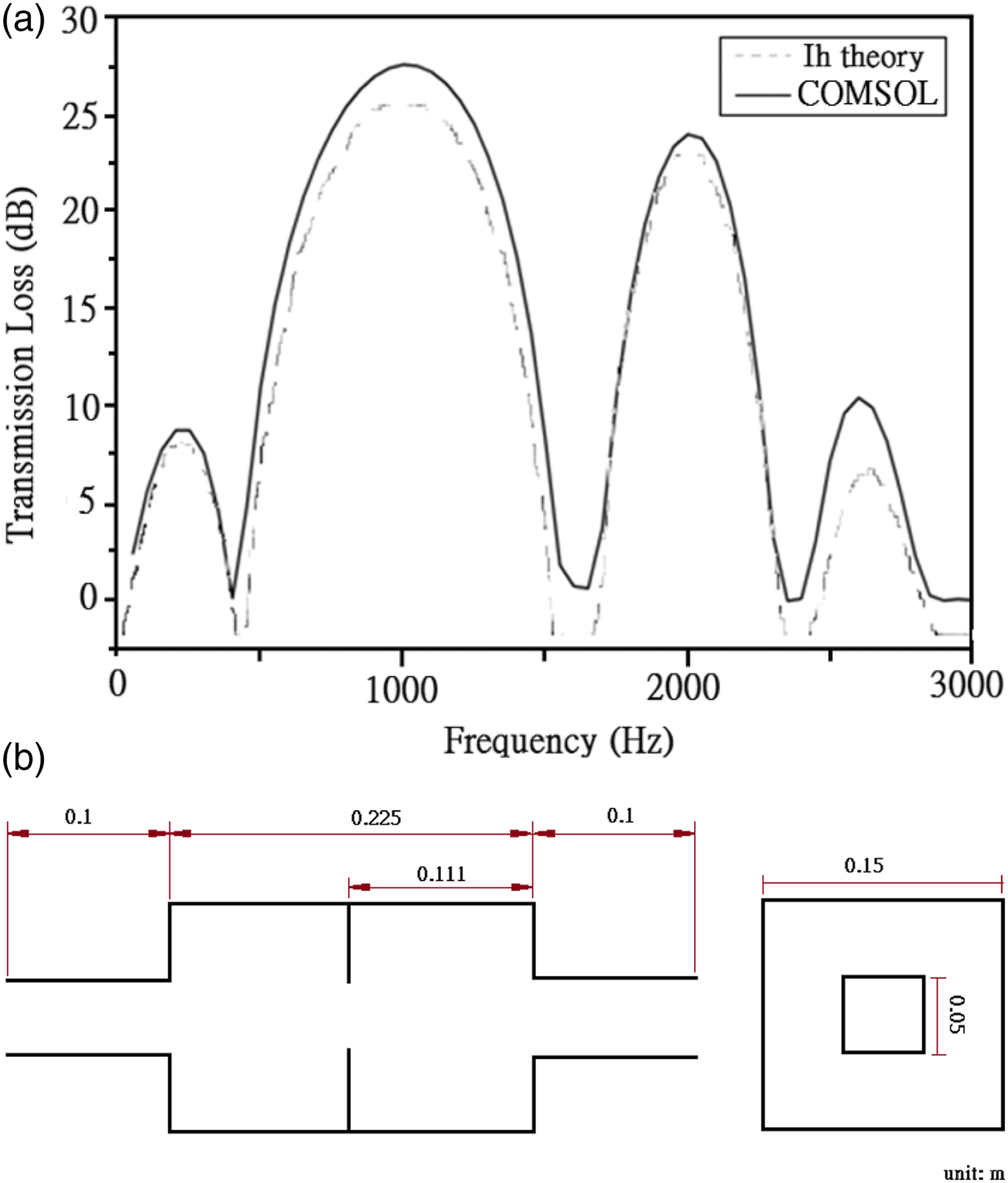
Result reveals that the tendency of TL curve to the experimental data is in agreement even though there is a little fluctuation occurred at 700 Hz, 2750 Hz, and 3100 Hz which is probably caused by experimental deviation errors. In addition, as depicted in Figure 3, the simulated TL of a muffler internally inserted with a baffle is also compared to the analytic data by Ih.
31
Result in Figure 3 discloses that they have the same tendency of the TL curves. Therefore, the accuracy of FEM model run on COMSOL is acceptable and will be applied in the following section. An accuracy check of the one-chamber muffler with internally extended and perforated tubes.
30
Accuracy check of an internally partitioned baffle chamber compared to IH’s theory
31
and COMSOL.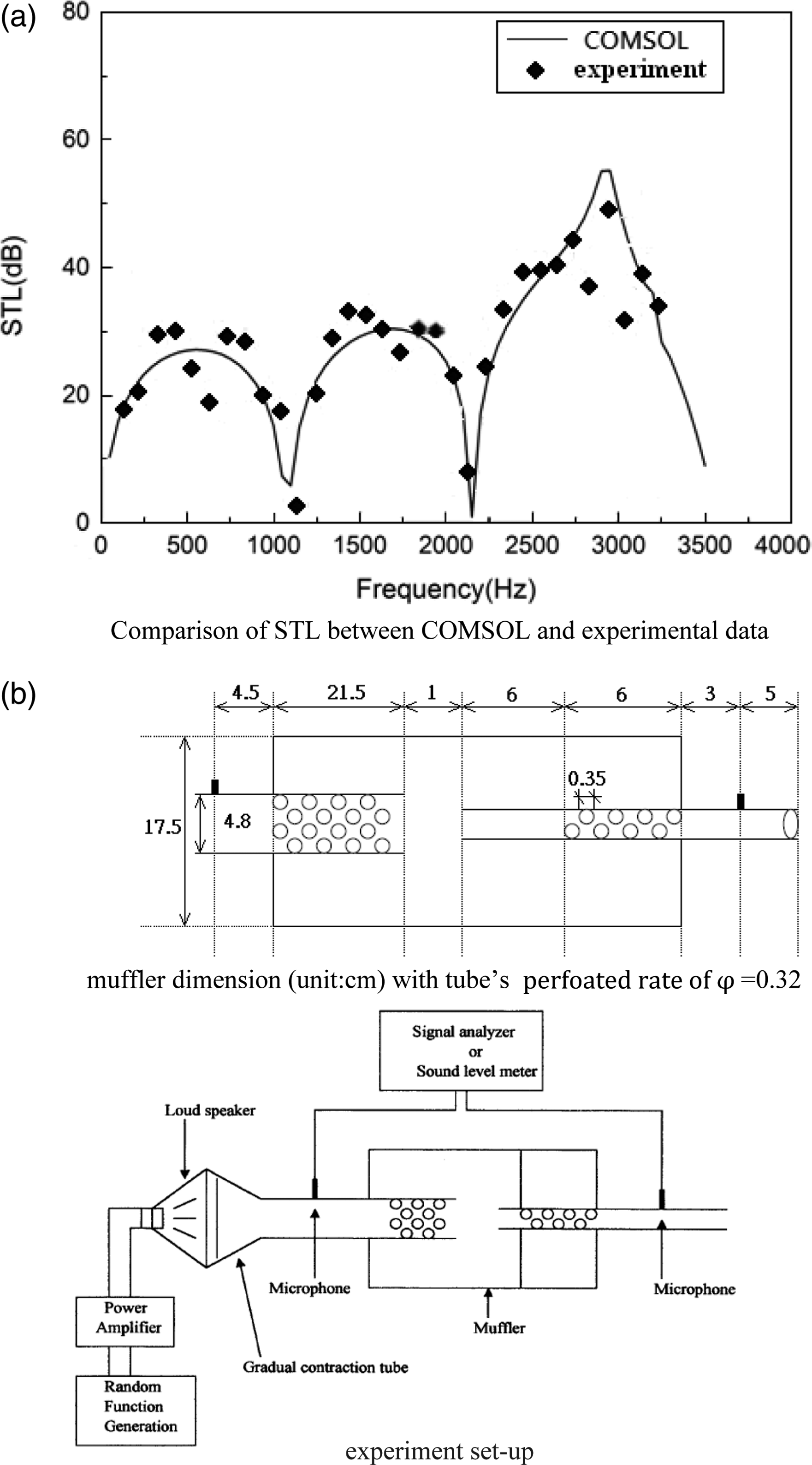
Artificial neural network model
The structure of ANN (Artificial Neural Network) is depicted in Figure 4. As illustrated in Figure 4, because of the hidden layers inside the ANN structure, the mathematical function of ANN is in an implicit form which will cause the inconvenience during the calculation process. Therefore, in order to enable the calculation, an explicit form using a polynomial neural network is obligatory. As can be seen in Ivakhnenko’s research work ,
32
these interconnections within the layers of neurons are simplified. In addition, the related weight factor can be adaptably adjusted and the coefficients of polynomial transfer functions can be easily calculated when using the polynomial neural network in conjunction with a regression process. As depicted in Figure 4, for a network with h number of hidden layer, the total output of neural network yields The structure of a polynomial neural network.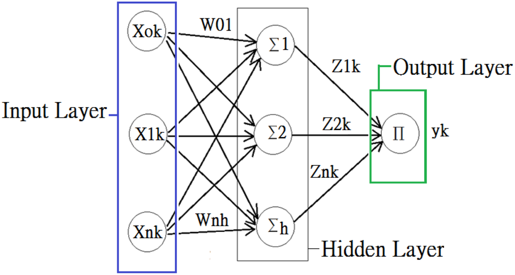

Expanding equation (8) yields

Subsequently, the ANN model is trained and tested by inputting both the training data bank and the testing data bank. The related data bank is composed of design parameters and theoretical TL which is obtained from the COMSOL’s acoustical simulation. The polynomial calculation together with the PSE standard will be carried out. The PSE (a deviation of mean square) yields

Genetic algorithm
Based on the concept of Darwinian natural selection, Holland
33
invented a Genetic Algorithms (GA). Later, Jone
34
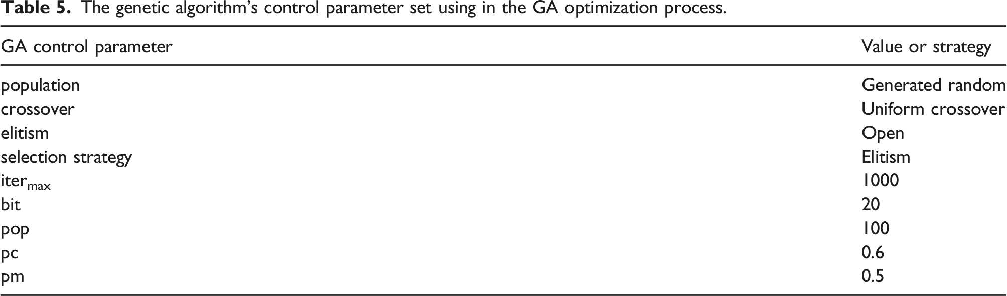
extended the GA theory to practical application. And, because of great ability in the global searching, the application of GA method has been widely developed in many fields.35,36 To efficiently search for global optimum in the muffler design work, the GA optimization will be adopted and in conjunction with ANN model and COMSOL. Here, seven kinds of GA’s control parameters, including gene population (pop), a length of chromosome (bit), a selection strategy (elitism), a mutation ratio (pm), a crossover ratio (pc), and a maximum iteration (itermax), are chosen. The related GA optimization process is depicted in Figure 5. As illustrated in Figure 5, each pair of candidate parents will be chosen via coding, decoding process and linked to the ANN model (a simplified objective function). The precision (MM) of parameter set’s search is Flow chart of GA optimization.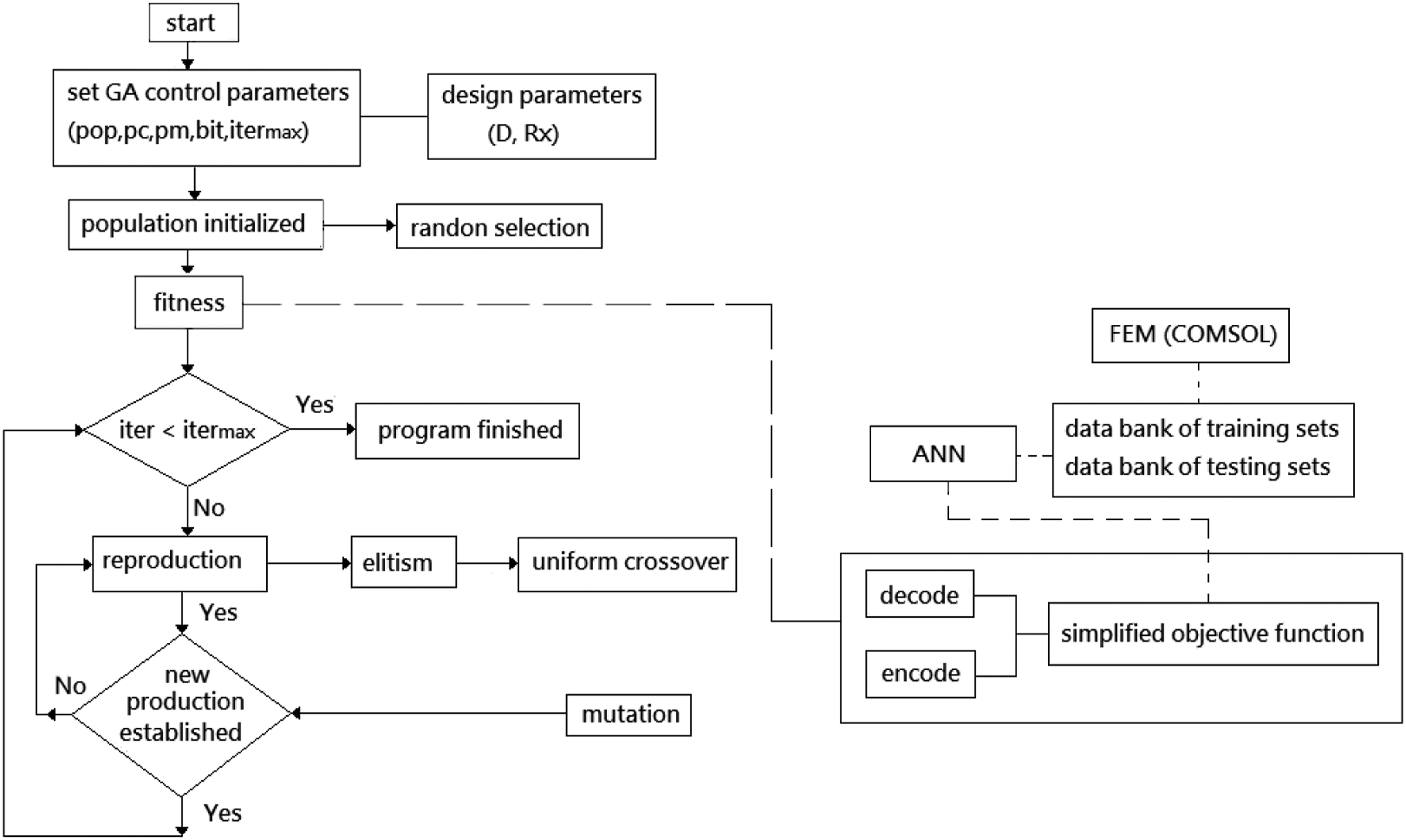

Sensitivity analysis
Concerning about the acoustical influence with respect to various acoustical elements which are located inside the muffler, several kinds of design parameters are chosen as the target parameters during the following acoustical sensitivity analysis.
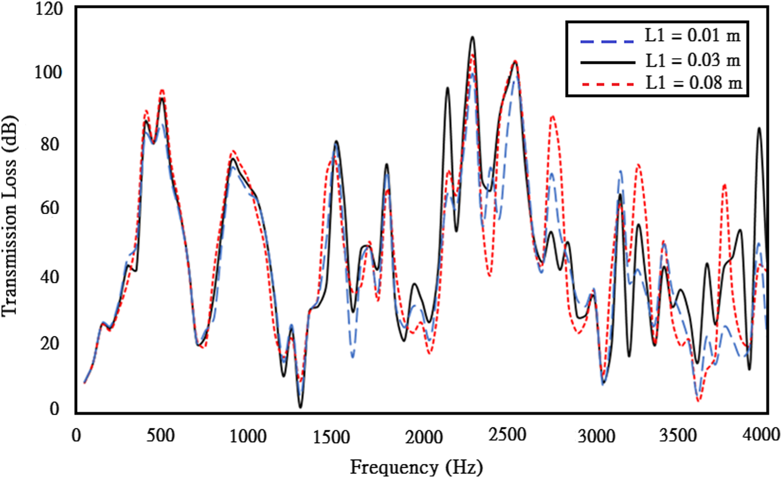
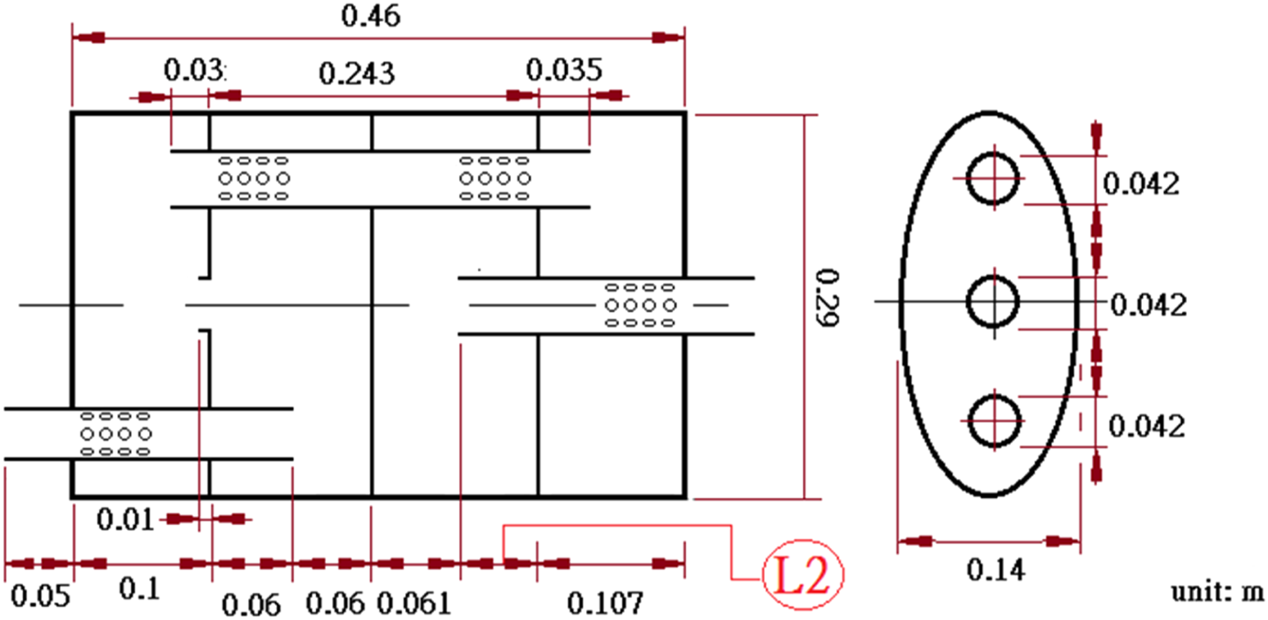
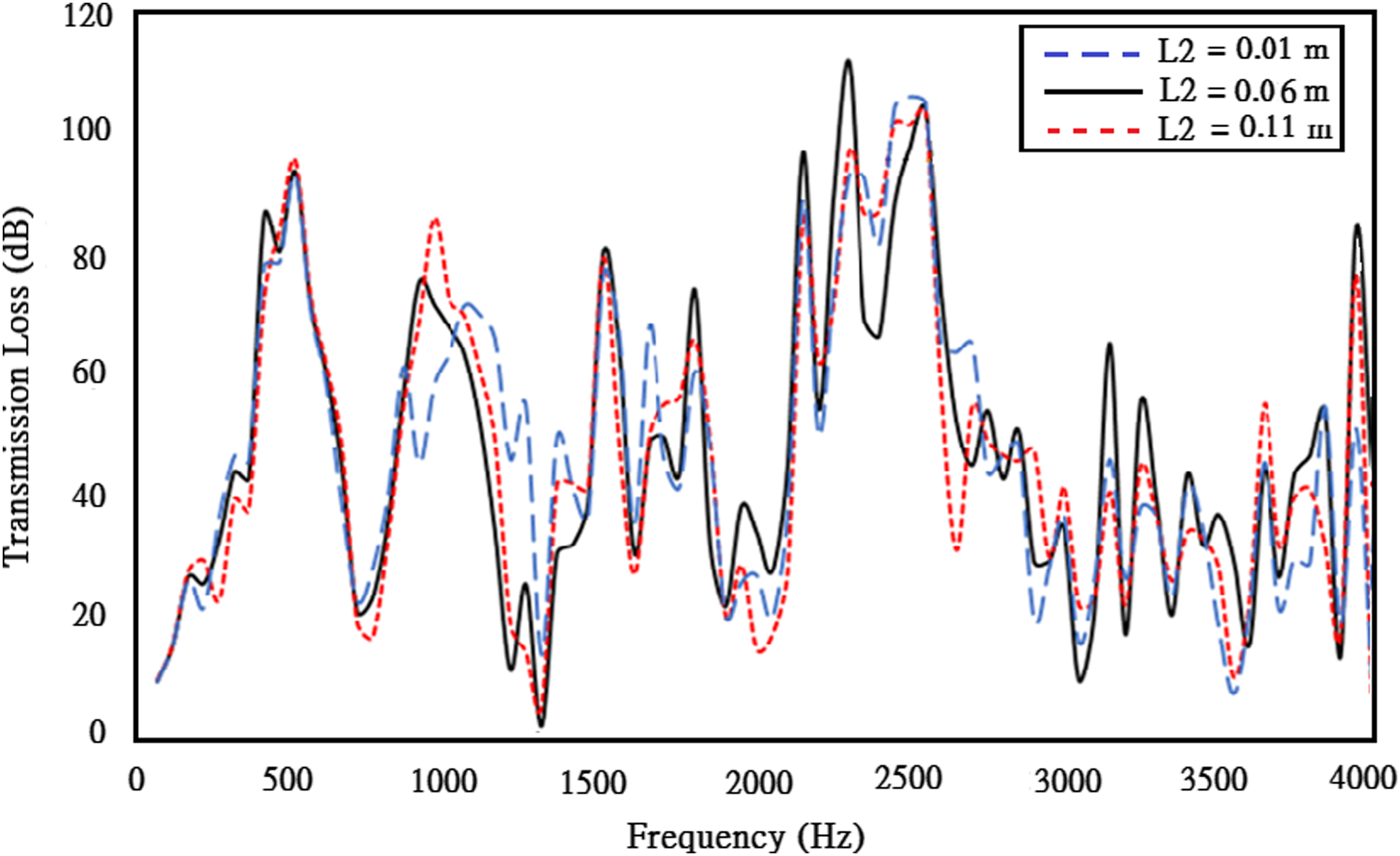
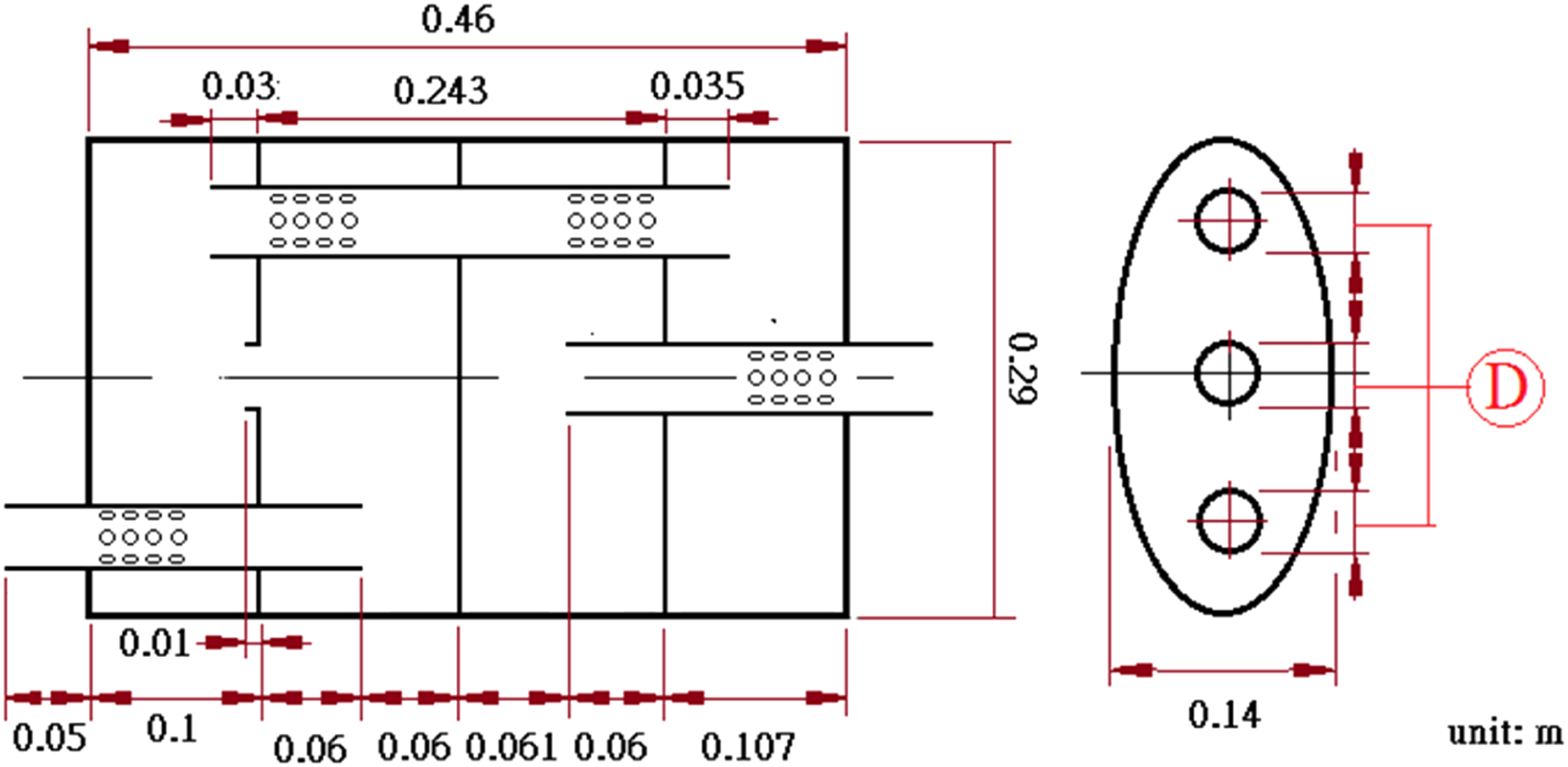
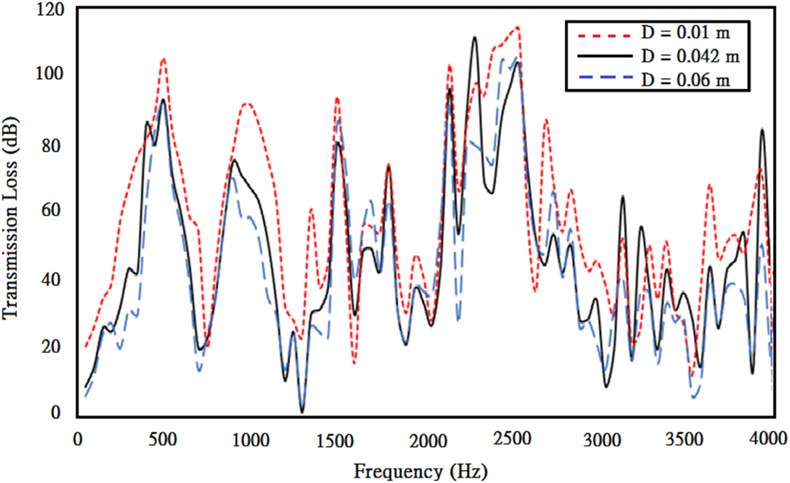
As indicated in Figure 6, L1 (length of the first chamber’s upper tube) has been selected as a design parameter. Result in Figure 7 reveals that the TL will be fluctuated when varying the L1. The TL will increase when L1 increases at the frequency region of 1500 Hz below. Apparently, a reactive effect at low frequency is obvious when the length (L1) of non-perforated tube increases. Similarly, as illustrated in Figure 8, L2 (length of the third chamber’s middle tube) is chosen as the design parameter. The simulated result plotted in Figure 9 also indicates that the fluctuation of TL is also obvious if varying the value of L2. There is a trend that the TL curve will be horizontally shifted when tuning the perforated tube’s length. Moreover, the D (diameter of the perforated/non-perforated tube) is selected as the design parameter and shown in Figure 10. The influence of TL curve with regard to D depicted in Figure 11 shows that the TL will proportionally increase if D decreases. Subsequently, the acoustical influence with respect to X (horizontal length of the muffler’s body portrayed in Figure 12) is also investigated. As illustrated in Figure 13, the fluctuation of TL is large when adjusting the value of X. There is a trend that the TL will increase at the frequency region of 1500 HZ below when X increases. The selected parameter of L1. The influence of TL with respect to L1. The selected parameter of L2. The influence of TL with respect to L2. The selected parameter of D. The influence of TL with respect to D. The selected parameter of X. The influence of TL with respect to X.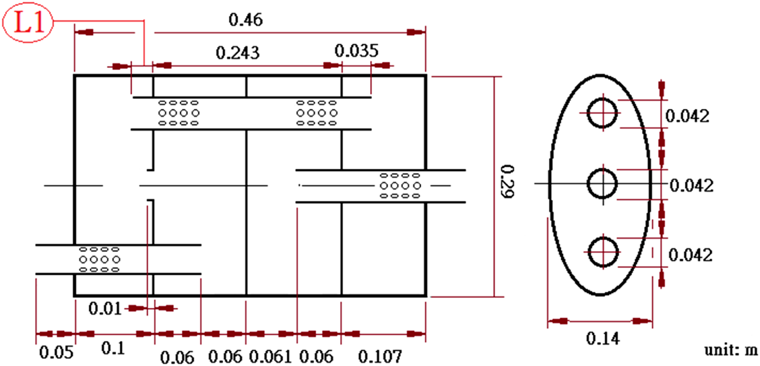
Furthermore, considering the ellipse’s curvature effect, both of AA and BB (the lengths of ellipse muffler’s two axes shown in Figure 14) are adjusted and the ellipse’s curvature δ defined by AA/BB is selected as the design parameters. The influence of TL with respect to curvature δ is analyzed and displayed in Figure 15. As seen in Figure 15, the fluctuation of TL is huge when the curvature δ varies. As shown in Figure 15, the TL decreases at the frequency region of 1500 Hz below when the curvature δ increases. The selected parameters of AA and BB (the lengths of muffler’s two axes). The influence of TL with respect to curvature ratio δ (=AA/BB).
Case study
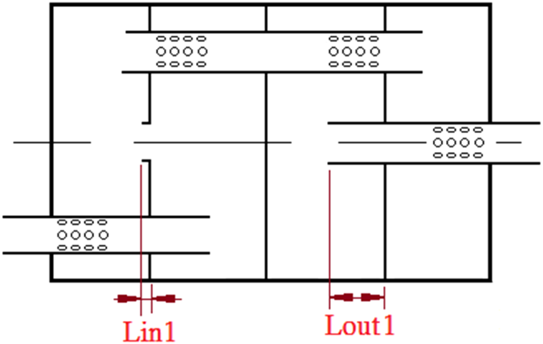
In order to improve the acoustical performance of muffler, a four-chamber and eccentric ellipse muffler internally divided by three baffles, and inserted with four segments of perforated/non-perforated tubes is introduced. As mentioned, the influence of TL with respect to geometric parameter sets, including L1, L2, D, X, and AA and BB, have been assessed. Results signify that the TL relating to these design parameters is sensitive. In order to evaluate an optimal design data of the four-chamber and eccentric ellipse muffler, two kinds of design parameter sets, including (Lin, Lout) and (Lin1, Lout1) shown in Figure 16 and Figure 17, have been adopted in the muffler optimization in case I and case II. Here, Lin is the length of the second chamber’s lower tube, Lin1 is the length of the first chamber’s middle tube, and Lout (=Lout1) is the length of the third chamber’s middle tube. The selected design parameters of Lin and Lout used for muffler optimization (case I). The selected design parameters of Lin1 and Lout1 used for muffler optimization (case II).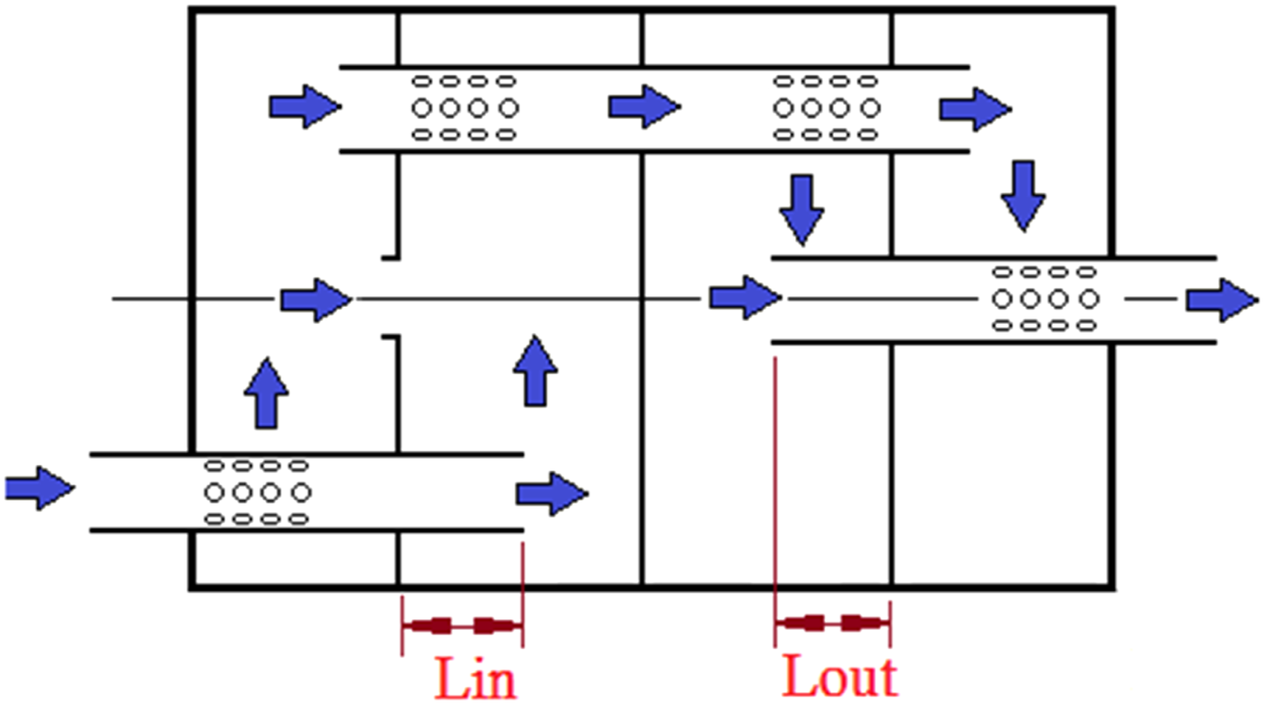
Case I
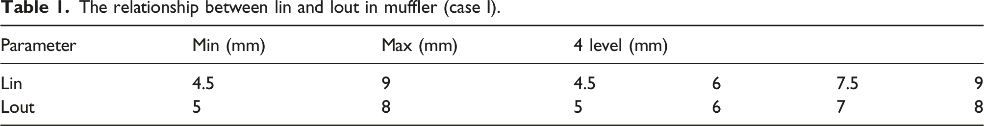
The relationship between lin and lout in muffler (case I).
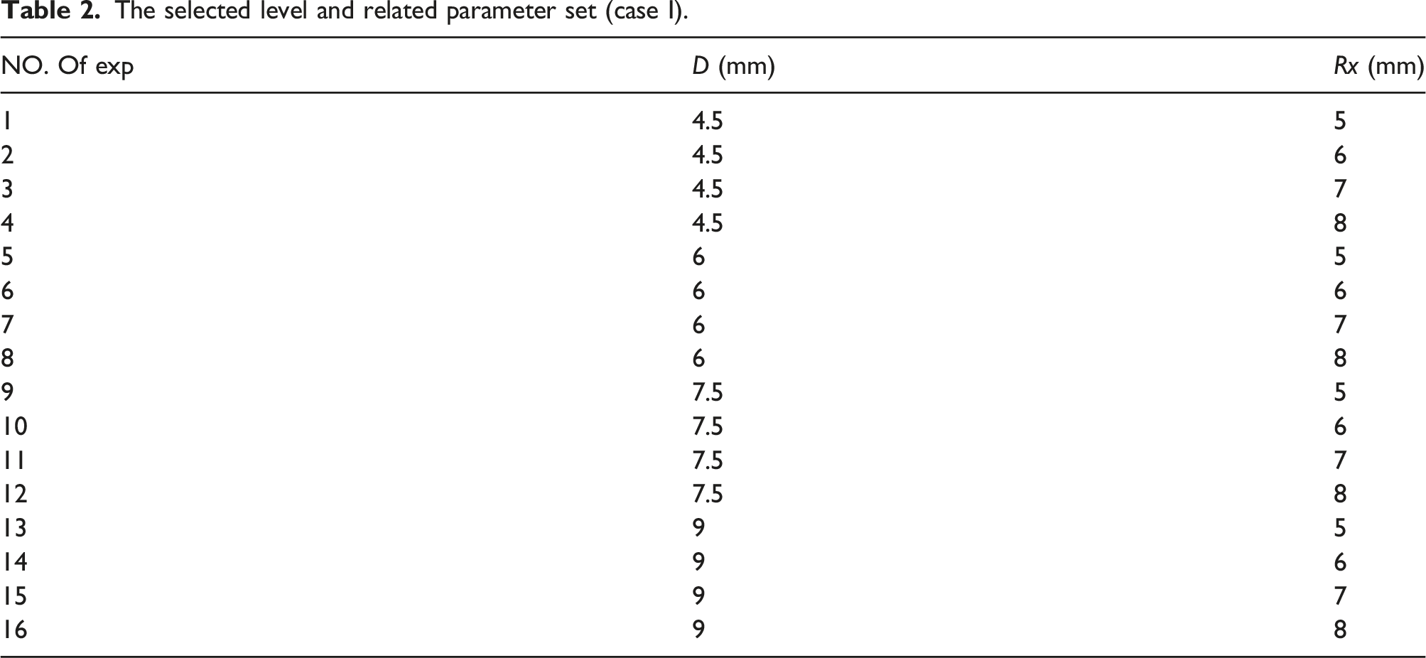
The selected level and related parameter set (case I).
Target Frequency — 1000 Hz


Target Frequency — 2500 Hz


Case II
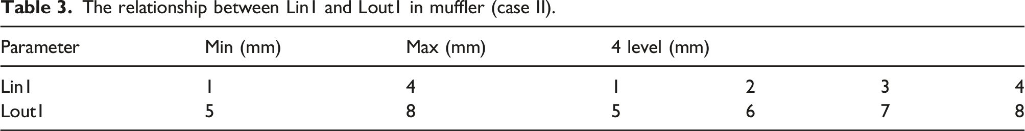
The relationship between Lin1 and Lout1 in muffler (case II).
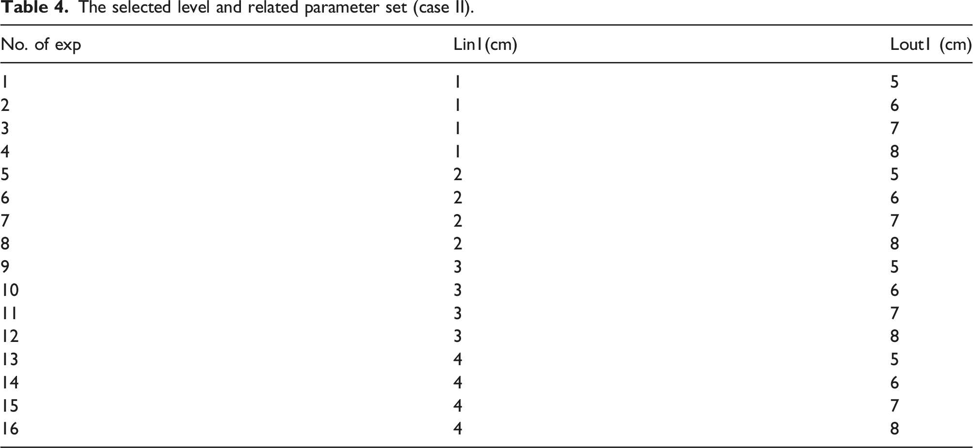
The selected level and related parameter set (case II).
Target frequency — 1000 Hz


Target frequency — 2500 Hz


Results and discussion
Results
Case I
The genetic algorithm’s control parameter set using in the GA optimization process.
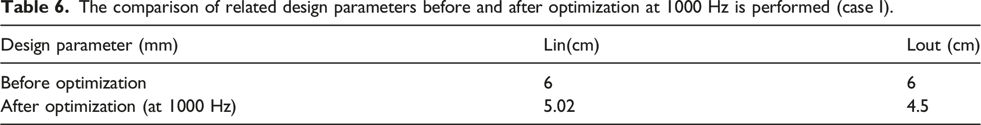
The comparison of related design parameters before and after optimization at 1000 Hz is performed (case I).
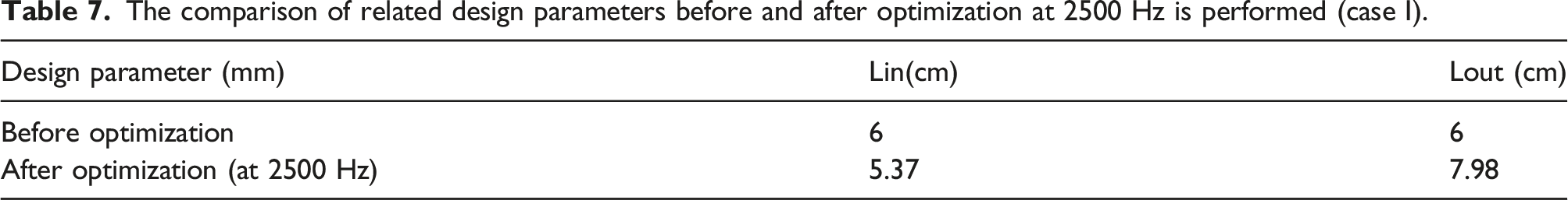
The comparison of related design parameters before and after optimization at 2500 Hz is performed (case I).
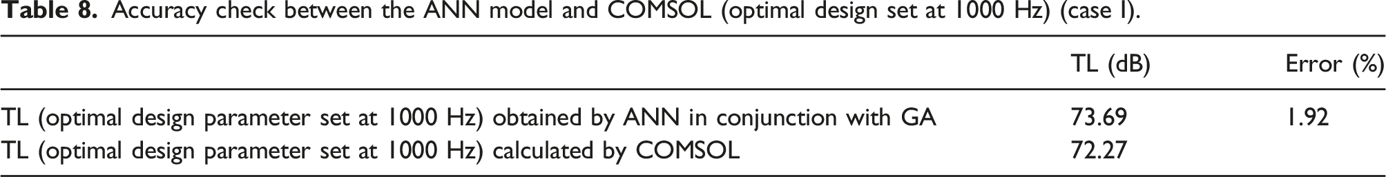
Accuracy check between the ANN model and COMSOL (optimal design set at 1000 Hz) (case I).
Accuracy check between the ANN model and COMSOL (optimal design set at 2500 Hz) (case I).

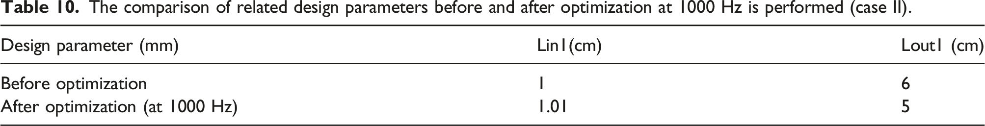
The comparison of related design parameters before and after optimization at 1000 Hz is performed (case II).
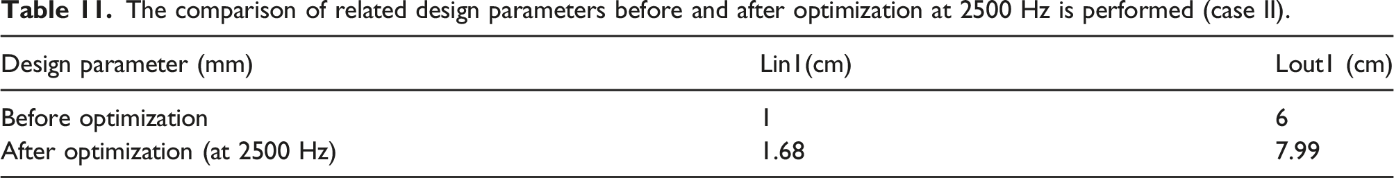
The comparison of related design parameters before and after optimization at 2500 Hz is performed (case II).
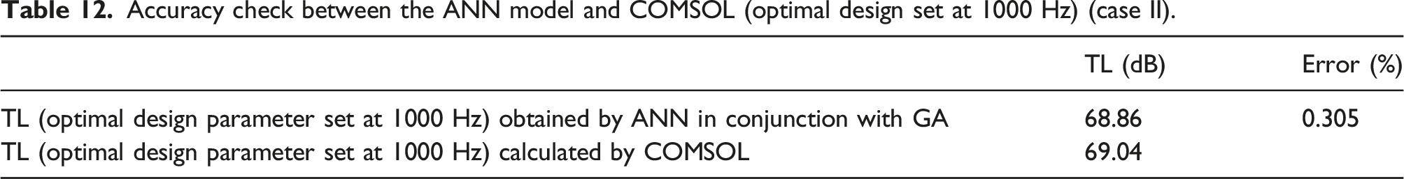
Accuracy check between the ANN model and COMSOL (optimal design set at 1000 Hz) (case II).
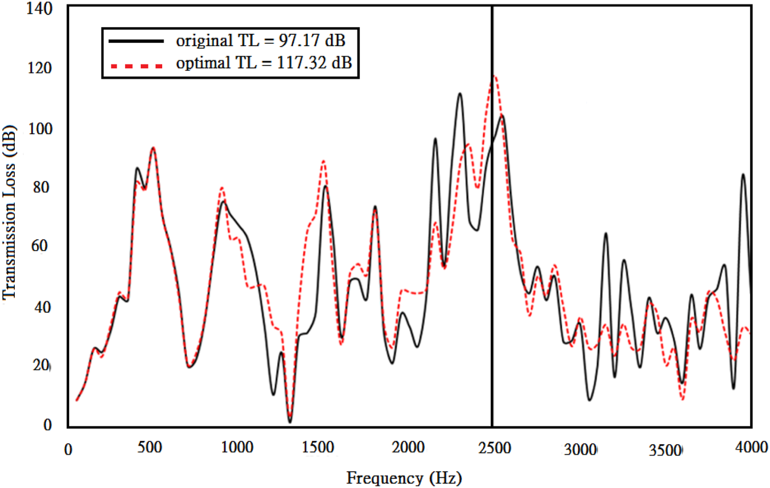
Bring original data and optimal design data into COMSOL, the theoretical TL’s profiles before and after optimization is performed are plotted in Figure 18 and Figure 19. As displayed in Figure 18, the TLs at the targeted frequency of 1000 Hz before and after the optimization is implemented are 67.3 dB and 72.2 dB. Moreover, as depicted in Figure 19, the TLs at the targeted frequency of 2500 Hz before and after the optimization is performed are 97.1 dB and 117.3 dB. The comparison of TL before and after the optimization is performed (target frequency of 1000 Hz) (case I). The comparison of TL before and after the optimization is performed (target frequency of 2500 Hz) (case I).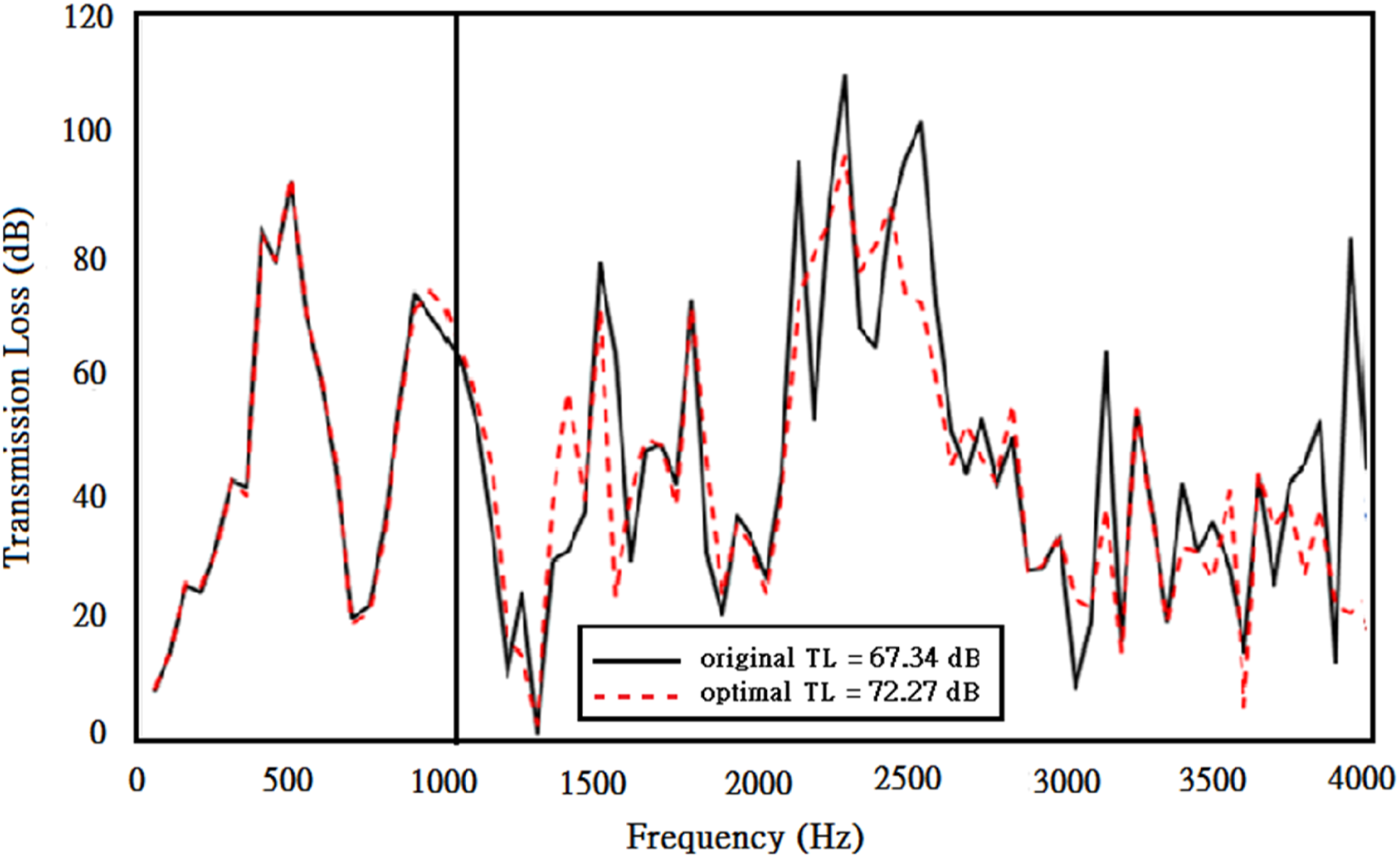
Case II
Accuracy check between the ANN model and COMSOL (optimal design set at 2500 Hz) (case II).

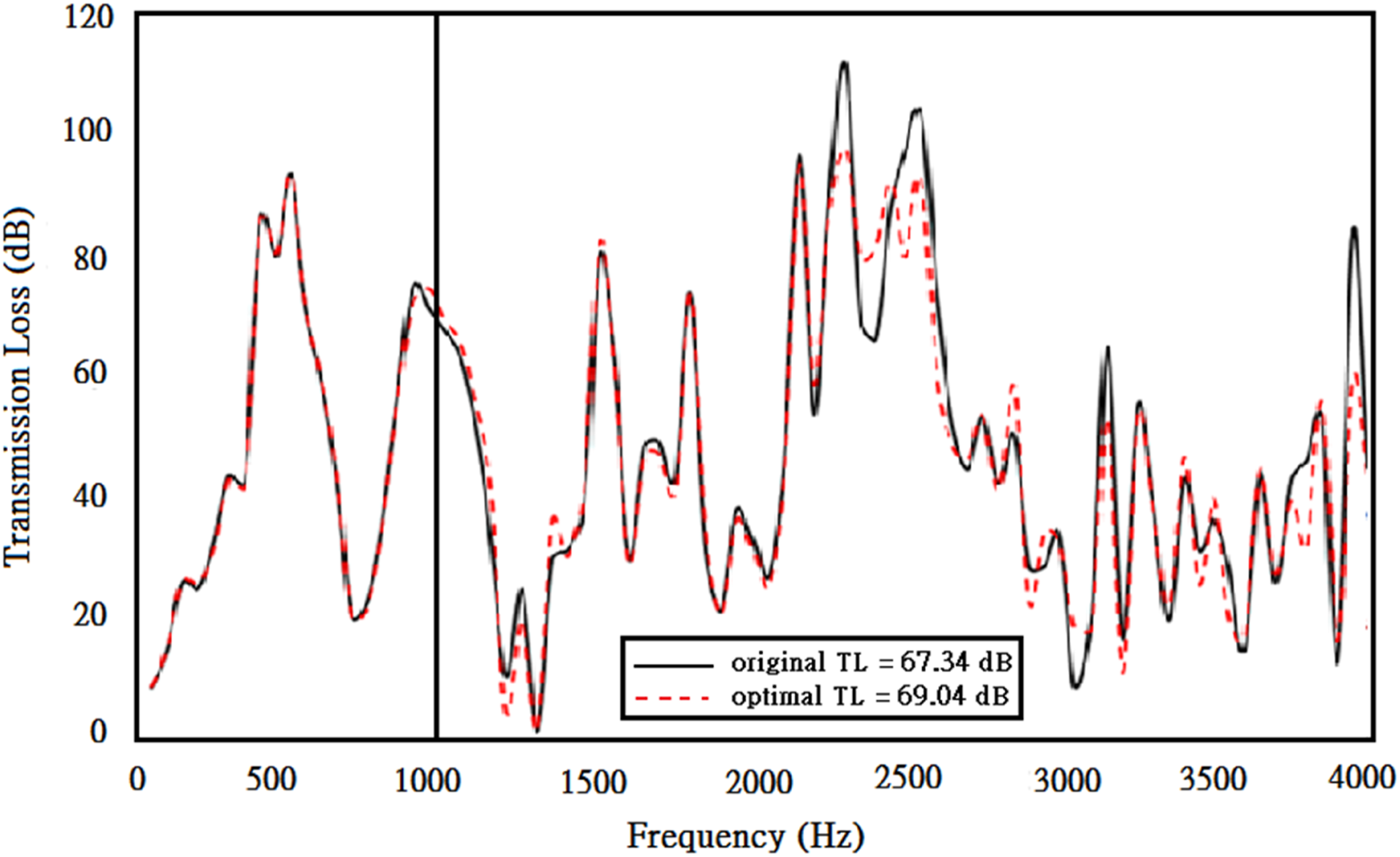
The comparison of TL before and after the optimization is performed (target frequency of 1000 Hz) (case II).
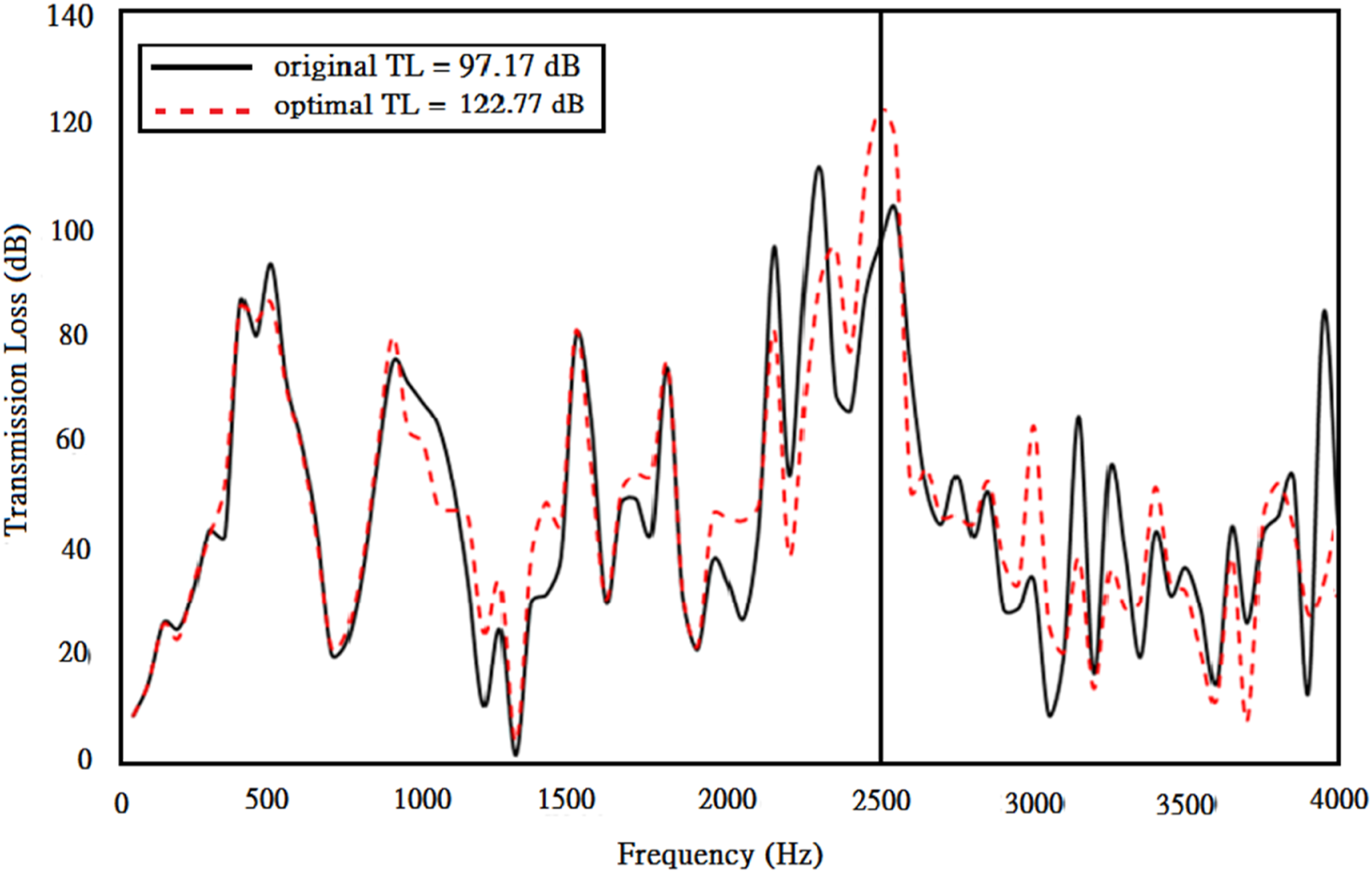
The comparison of TL before and after the optimization is performed (target frequency of 2500 Hz) (case II).
Discussion
As seen in Sensitivity Analysis, the influence of TL with respect to five kinds of geometric data, including L1, L2, D, X, and δ, is obvious. The tendencies of L1 and X are positively related to TL at the frequency regions of 1500 Hz below. And, the curvature ratio δ is negatively related to TL at the frequency regions of 1500 Hz below. For the influence of L2 to TL curve, the TL will be tuned and horizontally shifted when the L2 (length of the third chamber’s middle tube) varies. Regarding to the influence of TL to D (diameter of the perforated/non-perforated tube), it is obvious that the TL increases when D decreases.
In order to explore an optimal design data of the four-chamber and eccentric ellipse muffler, two kinds of design parameter sets, including (Lin, Lout) and (Lin1, Lout1) shown in Figure 16 and Figure 17, have been adopted in the muffler optimization and discussed in case I and case II, individually. For case I, the simulated results of Figure 18 and Figure 19 point out that the noise abatement of muffler at the target tones of 1000 Hz and 2500 Hz can be improved by 4.9 dB and 20.2 dB when using optimization process. Moreover, as indicated in Table 8 and Table 9, the accuracy of ANN model confirmed by the FEM’s simulation is between 1.92% and 3.74%. Similarly, the simulated results in case II are depicted in Figure 20 and Figure 21. Results in Figure 20 and Figure 21 reveal that the noise abatement of muffler at the target tones of 1000 Hz and 2500 Hz can be improved by 1.7 dB and 25.6 dB after performing optimization process. And, as illustrated in Table 12 and Table 13, the accuracy of ANN verified by FEM’s simulation is between 0.305% and 9.08%. Furthermore, as indicated in Table 6 and Table 7, the maximal TLs (case I) at targeted frequencies of 1000 Hz and 2500 Hz reach if (Lin and Lout) is justified from (6m, 6m) to (5.02 m, 4.5 m) and (5.37 m, 7.98 m). And, as shown in Table 10 and Table 11, the maximal TLs (case II) at targeted frequencies of 1000 Hz and 2500 Hz reach if (Lin1 and Lout1) is justified from (6m, 6m) to (1.01 m, 5m) and (1.68 m, 7.99 m). Apparently, the TL curve can be tuned and shifted by adjusting the length of horizontal tube which has the reactive effect in muffler.
Conclusion
In order to improve the acoustical performance of mufflers, a four-chamber and eccentric ellipse muffler internally partitioned with three baffles and inserted with four perforated/non-perforated tube has been proposed. Before the muffler optimization is performed, a sensitivity analysis for the muffler’s acoustical performance to geometric factors is explored. Result of sensitivity analysis shows that the geometrical parameters of L1, L2, D, X and δ have large influences to the muffler’s acoustical performance. Both of L1 and X are positively related to the TL cure at frequency zone of 1500 Hz below. In addition, the TL curve is negatively related to the δ at the frequency region of 1500 Hz below. For the relationship between TL and L2, TL will be resonated and shifted at certain frequency when L2 is adjusted. Moreover, the whole TL curve will increase when D decreases. Apparently, L1, L2, D, X and δ have reactive effect to the muffler and will lead to TL’s fluctuation. And, the reactive effect is also remarkable at the lower frequency region of 1500 Hz below when varying L1, X and δ.
To enable advanced muffler optimization, a neural network (ANN) model served as a simplified objective function and linked to a GA optimizer during optimization process is adopted. Concerning human’s hearing health, two sensitive frequencies of 1000 Hz and 2500 Hz are chosen as the targeted frequencies. To seek for an optimally shaped muffler, two kinds of design parameter sets, including (Lin, Lout) and (Lin1, Lout1), are considered in the muffler optimization and discussed in case I and case II, individually. Results reveal that the TL (case I) at target tones of 1000 Hz and 2500 Hz reaches 73.69 dB, and 121.8 dB when the GA control parameter set (pm, pc, pop, bit, itermax) is (0.5, 0.6, 100, 20, 1000). The accuracy verification of ANN (case I) at target frequencies of 1000 Hz, and 2500 Hz is 1.92%, and 3.74%. Similarly, using the same GA control parameter set (pm, pc, pop, bit, itermax), TL (case II) at target tones of 1000 Hz and 2500 Hz reaches 68.86 dB, and 135.04 dB. The related accuracy verification of ANN (case II) at target frequencies of 1000 Hz, and 2500 Hz is 0.305%, and 9.08%, respectively. Furthermore, results reveal that the TL curve will tuned up and horizontally shifted when the lengths of horizontal tubes (Lin, Lout, and Lin1) are optimally adjusted. Actually, the lengths of horizontal tubes have a reactive effect to the muffler’s TL. Presently, the mathematical model used in the paper does not consider the influence of acoustical performance relating to flow, heat, and gas composition. Nonetheless, an effort by including these parameters into the mathematical model is possible and will be planned in future work.
Consequently, the acoustical analysis of above four-chamber and eccentric ellipse muffler can deliver a design concept to the muffler engineer in adjusting the related geometric parameters. And, this paper also demonstrated an easy way in optimizing a multi-chamber and eccentric ellipse muffler.
Footnotes
Declaration of conflicting interests
The author(s) declared no potential conflicts of interest with respect to the research, authorship, and/or publication of this article.
Funding
The author(s) received no financial support for the research, authorship, and/or publication of this article.
Nomenclature
This paper is constructed on the basis of the following notations: