
Abstract
In this study, an optimized dynamic vibration absorber (DVA) was applied to improve the sound absorption performance and simultaneously attenuate vibrations and structure-borne noise at multiple frequencies. As the size parameters and eigenfrequencies of a DVA demonstrate a nonlinear relationship, tuning the eigenfrequencies by heuristically modifying the geometric parameters of the DVA is difficult. To avoid this intricate process, geometric parameters were optimized using a gradient method solver to tune the eigenvalues of the DVA to the target frequencies. Post-processing was performed for the sake of manufacturing. To confirm the validity of the performance of the sound absorption and vibration/noise attenuation, impedance tube experiments and impact experiments were conducted using the manufactured DVA. The impedance tube experiment verified that the values of the sound absorption coefficient increased with the application of the DVA. From the impact experiments, it was verified that the values of the frequency response function and sound pressure level decreased with the application of the DVA. The present study validates the notion that optimized DVAs improve the sound absorption performance of structures and simultaneously reduce vibrations and sound pressures at multiple desired frequencies.
Introduction
Vibration and sound pressure reduction is an important subject in the field of engineering. To analyze structural vibrations and sound pressures, several studies have been conducted on noise sources inside electric vehicles, 1 sound emission characteristics of wheel parts, 2 advanced sound radiation models of tires with contact, 3 and sound radiations of refrigerator noise. 4 Studies have also analyzed sound pressures and vibrations generated by plate structures, which are widely used in engineering environments. Relevant research has been conducted on the sound radiation of rectangular orthotropic plates resulting from forced excitation 5 and on prediction models for sound radiation of plate-like structures. 6 Moreover, studies have investigated the sound radiation of complicated structures such as box structures, including structural-acoustic vibrations in paneled boxes, 7 sound radiation characteristics of a box-type structure using the finite element method and boundary element method, 8 and sound radiation of hollow box timber floors using impact excitation. 9 To reduce sound pressures using existing engineering methods and approaches, most studies have employed sound absorbers. Methods using metamaterial beams consisting of a uniform isotropic beam and an arrayed small two-mass spring-mass damper, 10 meta-surface absorbers based on the slow wave effect, 11 meta-surface–based perfect absorbers, 12 broadband compact acoustic absorbers, 13 locally resonant metamaterials consisting of a subwavelength array of resonators, 14 and photonic blackholes 15 have been proposed to attenuate the sound pressure of structures using metamaterials. Methods using composite structures consisting of embedded I-plates with porous polyurethane sponges 16 and composite-loaded sound absorbers using a Helmholtz resonator have also been proposed to reduce sound pressures of structures using porous foams. Several innovative analyses have also considered sound absorbers using impedance-matched absorbing surfaces 17 and optimized damping treatments. 18
Dynamic vibration absorbers have traditionally been employed in several engineering fields for vibration attenuation. Several studies considering DVAs have aimed to reduce the vibrations of rotating cutting tools 19 to effectively suppress resonant vibrations of a flexible car body 20 and to attenuate vibrations of vehicle suspension structures. 21 Furthermore, a few studies have attempted to improve the performance of DVAs. Methods using multiple nonlinear vibration absorbers for the mitigation of several nonlinear resonances and x-shaped tunable and nonlinear structures have also been presented to improve the vibration reduction performance of DVAs.22,23 Moreover, the power flow transmission characteristics of a system with and without DVAs have been investigated to evaluate the vibration reduction performance of DVAs. 24 Recently, the simultaneous reduction of sound pressure and vibration has emerged as an important issue, DVAs have received considerable attention for adjusting sound pressures in vibro-acoustic systems.25–28A DVA is a practical device for suppressing vibration and noise at a specific frequency by splitting and shifting the eigenfrequencies of a structure.29,30 Relevant research has been conducted using DVAs to investigate the vibration and noise control of fuselage31,32 and distributed absorbers that attenuate passive wide-band frequency vibrations. 33 Despite several contributions of DVAs, numerous limitations still exist; several sound absorbers have been designed to only reduce pressure at a single frequency value.
In other words, increasing the values of the sound absorption coefficient or lowering the values of the sound pressure level (SPL) at several frequencies is challenging. In this paper, an optimized dynamic vibration absorber (DVA) is presented to attenuate vibrations and sound pressures of structures at multiple desired frequencies. We adopt the mechanism of a previously developed DVA, which operates at multiple frequencies.
34
The parameters of the DVA were adjusted using the size optimization process to absorb vibrations and sound pressures at multiple targeted frequencies. There are several studies which are compared with the optimized DVA. Pendulum tuned mass damper commonly attenuates low frequency vibration due to the length limit of the pendulum.
35
Also, omnidirectional acoustic absorber using metamaterial reduced ineffectively in the frequency range bellow 1.2 kHz.
36
In addition, the single mass dynamic vibration absorber can only attenuate vibrations and noise at single frequency.
30
The double mass dynamic vibration absorber can increase the target frequencies, but it is limited to two.
37
In the case of parallel multi mass absorber, there is a disadvantage that the mass of the absorber increases when the number of target frequency is increased.
38
Compared with the other absorbers, the benefits of the optimized DVAs in this study lies in the fact that it is possible easily tune or optimize the geometric parameters of the DVAs to adjust wide-band target frequencies. It can reduce vibrations of hosting structures at multiple frequencies by utilizing their multiple modes. Figure 1 shows the effect of optimized DVA. The sound absorption coefficient is improved by attaching the optimized DVA to reduce the transmitted and reflective wave. Moreover, structure-borne noise is decreased by attaching the optimized DVA. The effects of the optimized DVA were experimentally verified by applying it to various structures. The purpose of the present research is to reduce vibrations and sound pressures at multiple targeted frequencies using an optimized DVA. Owing to the nonlinearity between the size parameters and eigenfrequencies, manually determining an optimal design with desired frequencies is challenging. Therefore, in this study, the optimization formula was formulated and solved using a numerical optimization algorithm and several constraints. A gradient-based optimizer (fmincon implemented in MATLAB) was employed to solve the size optimization problem. In the optimization formulation, the squared 2-norm of the differences between the frequencies of the DVA and the target frequencies was set as the objective function. Several parameters considering the size of the DVA were set as design variables. The optimized design variables were rounded to 0.1 mm for manufacturing during post-processing. To validate the proposed approach, several experiments were conducted with a circular plate, rectangular plate, and bottomless box structure. In the first example, the values of the sound absorption coefficient for the circular plate were improved by attaching an optimized DVA. The attached DVA affected the system of the circular plate and increased the value of the sound absorption coefficient at multiple targeted frequencies. The second and third examples were constructed to reduce vibrations and structure-borne noise using optimized DVAs. In the second example, vibrations and structure-borne noise of a rectangular plate were reduced using the optimized DVA. In the final example, vibrations and structure-borne noise of a simply supported bottomless box were attenuated using the optimized DVA. Analyses of these examples were conducted to verify the effects of optimized DVAs on increasing the values of sound absorption coefficients and attenuating the values of the frequency response function (FRF) and SPL for various structures. Schematic of vibration and sound pressure reduction with a dynamic vibration absorber: (a) improving sound absorption performance for normal incident sound and (b) reducing vibration and structure-borne noise.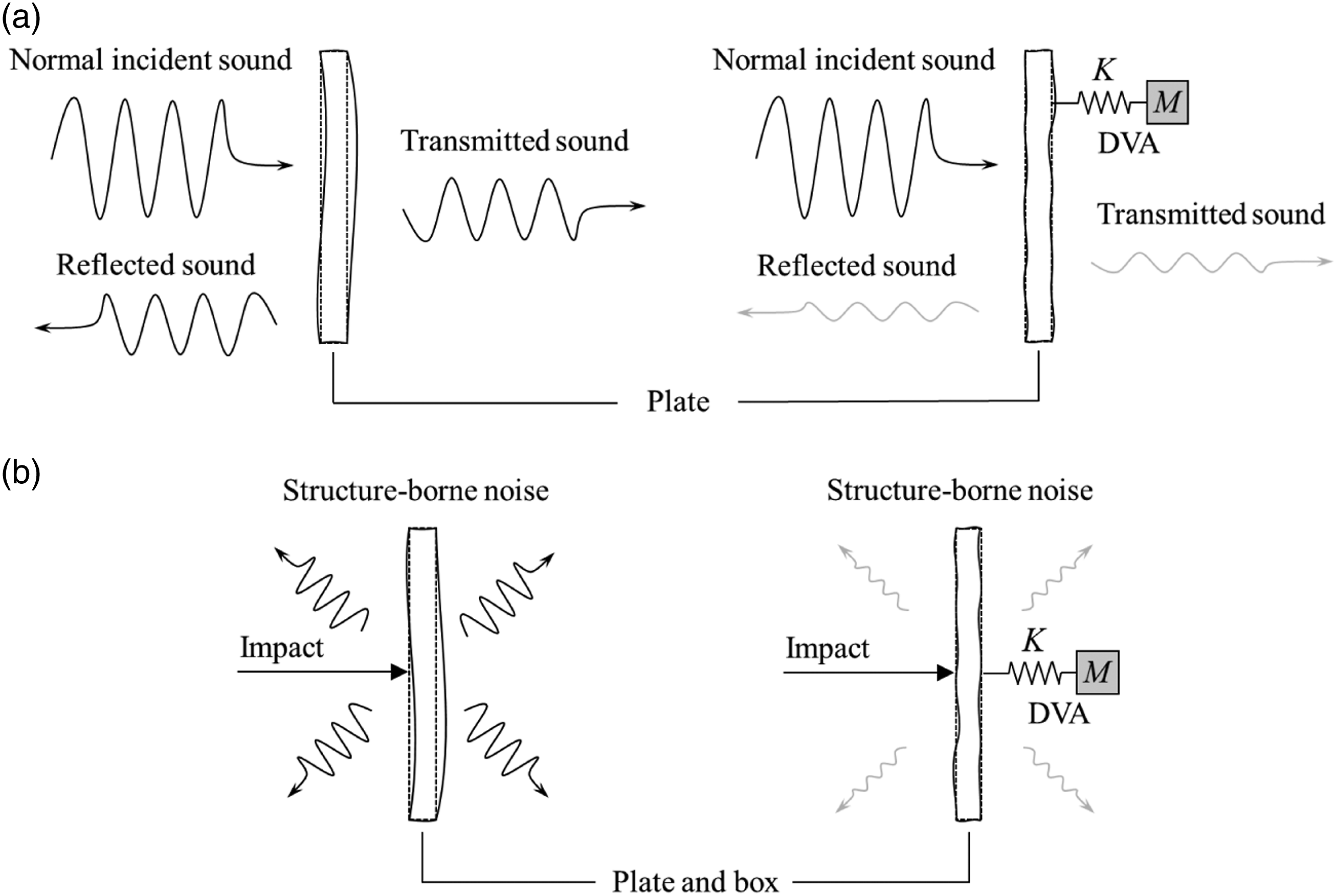
The remainder of this paper is organized as follows. Section 2 provides background information on dynamic vibration absorption at multiple frequencies. The advantages of the proposed DVA and size optimization procedure are also discussed. In Section 3, several optimizations and applications of the proposed DVA are presented. The experiments that were conducted to validate the performance of the designed DVAs are outlined herein. Section 4 provides conclusions and suggestions for future research.
Experimental method and tools
For the impedance tube experiment, the two microphones method is applied (Bruel Kær Type 4947(1/2-INCH PRESSURE-FIELD MICROPHONE, PREPOLARIZED)). For impact experiment, a uniaxial accelerometer (PCB Piezotronics model 352C33), an ICP-type impact hammer (PCB Piezotronics model 086C03), and a DAQ (NI cDAQ-9171, NI 9234) are employed. The signal processing (FFT) is carried out with MATLAB.
DVA for multiple frequencies
A DVA is a classical mechanical system used to attenuate vibrations. The principle of the DVA is to attach a spring–mass system to a system of interest for the absorption of vibration energy, as shown in Figure 1. In this study, the DVA shown in Figure 2 was adopted,
1
and it consists of three beams. Two identical beams with b
s
× l
s
× t
s
support a beam with l
m
× b
m
× t
m
(see Figure 2). The two beams function as springs, and the last beam functions as a mass. Two bending and twisting modes are observed. The eigenmodes of DVA are shown in Figure 6, Figure 8, Figure 12 and Figure 16. One of the benefits of this DVA is that it can simultaneously utilize the first three vibration modes and eigenfrequencies. It should be noted that the eigenfrequencies of the DVA depend on the values of the size parameters. Geometric parameters of the dynamic vibration absorber used in this study.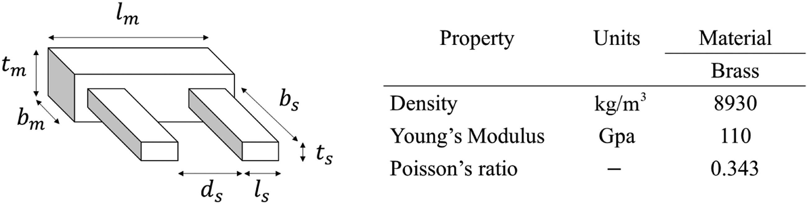
Size optimization for DVA
Manually determining the geometric parameters of the DVA, presented in Figure 2, to maximize its performance is challenging owing to the nonlinear characteristics of the eigenfrequencies and geometric parameters. Therefore, to effectively determine the geometric parameters of the DVA, we can adopt the structural optimization scheme presented in Figure 3. To consider the nonlinearity between the geometric parameters and eigenfrequencies, the optimizer, SQP(Sequential quadratic programming), is used. In the present study, a well-developed optimization algorithm in MATLAB (SQP) was adopted to solve an optimization formulation with an objective function with several constraints. The squared 2-norm of the differences between the frequencies of the DVA and target frequencies was set as the objective function. Seven geometric parameters existed in the proposed DVA system and were used as design variables. The following optimization formulation was set up to improve the eigenfrequencies of the DVA Optimization process of the present dynamic vibration absorber.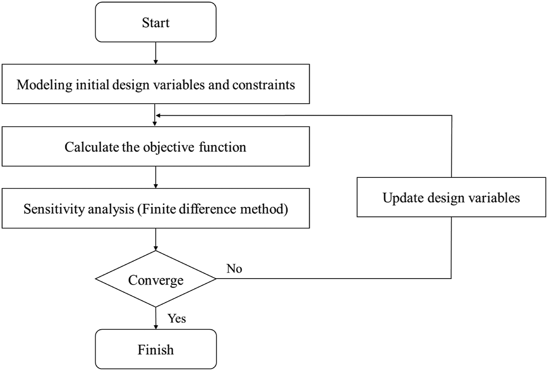
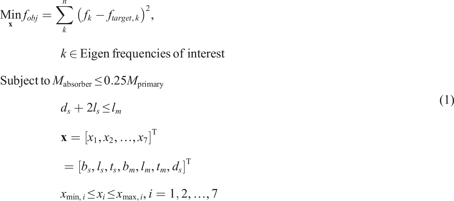
When DVA whose eigenvalues are tailored to the eigenvalues of target system, it effectively reduces the vibration and noise and increase the sound absorption coefficient. Where the target frequencies and actual eigenfrequencies of an intermediate design are denoted by f target , k and f k , respectively. The seven design variables denote the geometric parameters of the DVA. The mass of the absorber and that of the primary structure are denoted by Mabsorber and Mprimary, respectively. The DVA suppresses vibration and noise at a specific frequency by splitting and shifting the eigenfrequencies of a structure.19,20 By increasing the mass ratio Mabsorber and Mprimary m, commonly the gap between the split eigenfrequencies becomes wider. In this research, the mass ratio between DVA and structure is set under 0.25. Note that with a higher mass ratio than 0.25, the dynamic properties such as vibration mode, mode shape and eigenfrequencies are subject to be changed by DVA. The second constraint is imposed to satisfy the geometric constraint (see Figure 2). The lower and upper bounds of the design variables are denoted as xmin,i and xmax,i, respectively.
Figure 3 illustrates the optimization process. After initializing the design variables and the finite element model of the DVA system, the objective function and constraints are computed with respect to the given design variables. Sensitivity analysis is performed using the finite difference method. Subsequently, the gradient-based optimizer ( fmincon implemented in MATLAB) updates the current design variables to minimize the objective function while satisfying the constraints. We assume that at least one local optimum exists for the given target frequencies. If an obtained local optimum with a sufficiently small objective value does not exist, the initial design variables are altered, and the proposed optimization procedure is reapplied to obtain a better local optimum.
Application of the proposed DVA
Further, to prove the concept of a DVA operating at multiple frequencies in an acoustic-structure interaction system, we solved several optimization problems considering DVAs operating at multiple frequencies. The objective of the optimization problem was set to the norm of the differences between the frequency and target frequency values. After obtaining local optima with sufficiently small objective values from an engineering perspective, the designed DVAs were manufactured with brass and were then experimentally tested.
Example 1 Improvement of sound absorption with dynamic vibration absorber
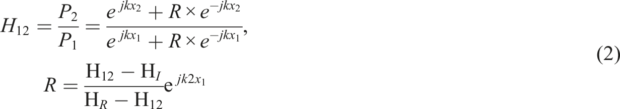
For the first example, two DVAs were designed to improve the absorption performance of circular plates, as shown in Figure 4(b). The determination of the sound absorption coefficient of a material is a well-developed acoustic theory. The sound incident on the surface of a material of interest is reflected, absorbed, and transmitted. The ratio of the reflected wave to the transmitted wave changes depending on the material of interest. To measure the absorption performance of a sound absorption material, an impedance tube can be employed, which measures the reflected sound wave based on the principle of standing waves. The impedance tube, illustrated in Figure 4(a), measures pressure values at two different locations. Subsequently, the following FRF is computed


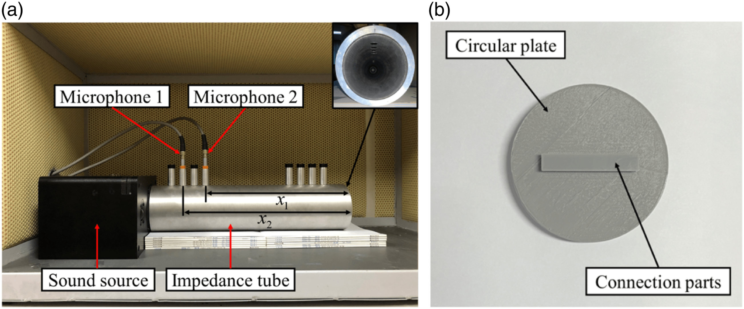
Acoustic experiment for the sound absorption coefficient: (a) experimental measurement setup and (b) circular plate.
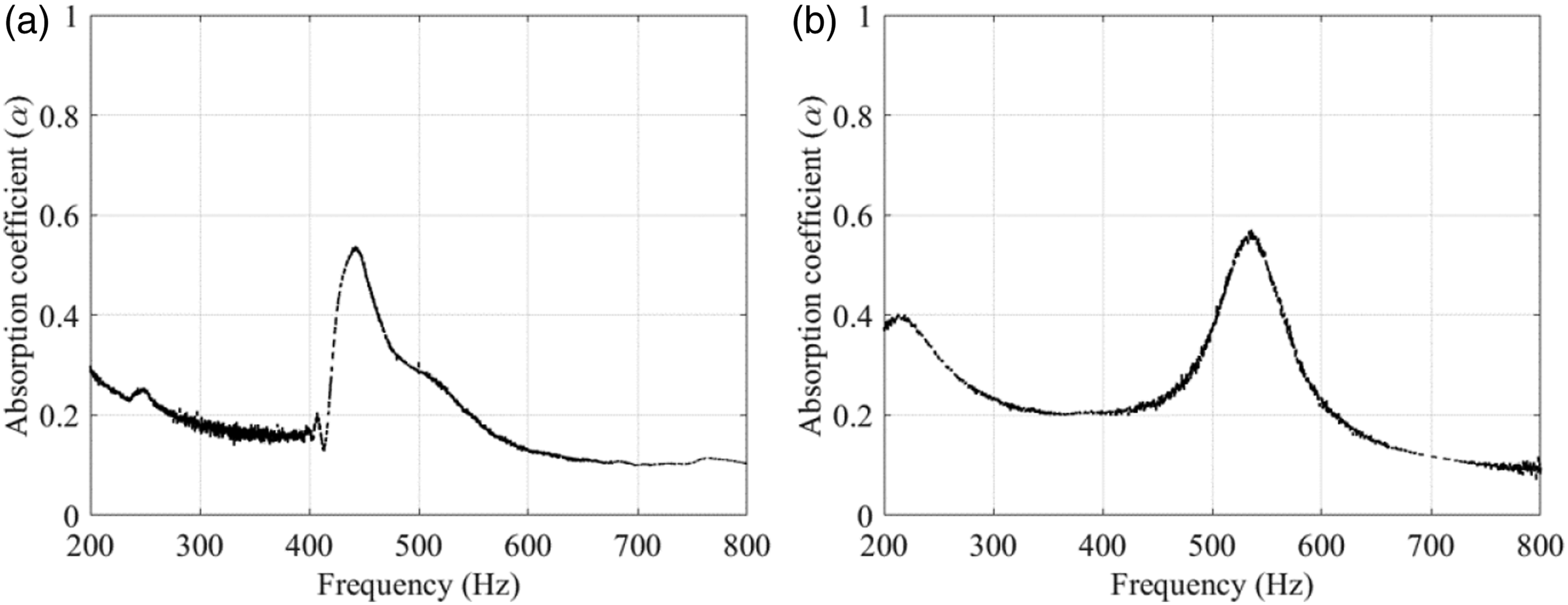
Sound absorption coefficients of the circular plate: (a) 430 Hz and (b) 530 Hz.
Optimization of DVA with two frequencies
In the first example, the DVA was optimized to improve the sound absorption coefficients at two target frequencies. The sound absorption coefficients of the circular plate are presented in Figure 5(a). The circular plate was placed at the right end of the tube, and a sound source and microphones were placed at the opposite end to measure the sound pressures at different locations between the sound source and circular plate (see Figure 4(a)). The experimental results revealed that the absorption coefficient was maximized at approximately 430 Hz. The maximized value of the sound absorption coefficient is determined by the eigenvalue of the circular plate.
39
To improve the sound-absorbing performance of the circular plate at multiple frequencies, a DVA can be attached. First, we aimed to design a DVA with eigenfrequencies of 300 Hz and 700 Hz. Consequently, an application of the DVA, with the two target eigenfrequencies, to the circular plate would allow the circular plate to achieve better sound absorption performance at both 300 Hz and 700 Hz. To achieve this, the following optimization formulation was considered
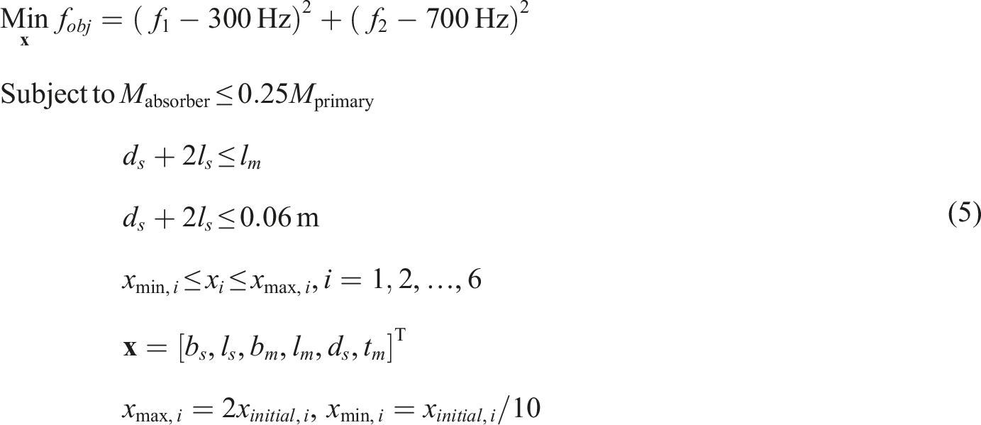
The design variables of the DVA are presented in Figure 2. The k-th eigenfrequency of the DVA is f
k
. The squared 2-norm of the differences between the frequencies of the DVA and the target frequencies was set as the objective function. The constraints were set by considering the mass and geometry of the DVA. The first constraint was imposed such that the mass ratio between the circular plate and DVA remained under 0.25, and the second constraint was imposed to maintain the configuration of the DVA, wherein two identical beams supported a single beam, as shown in Figure 2. The third constraint was imposed to ensure that the length of the DVA was less than that of the connection part of the circular plate. The fourth, fifth, and sixth constraints were imposed to set lower and upper bounds for the six design variables. The initial design variables, x
i
,
initial
, of the optimization problem were set to (0.0150 m, 0.0150 m, 0.0150 m, 0.0500 m, 0.0150 m, 0.0010 m). The upper and lower bounds of the design variables were set to twice and one-tenth the initial values of the design variables, respectively. As a brass plate with a thickness of 0.0005 m was prepared in the present case study, t
s
was set to 0.0005 m. The design variables after the optimization process are presented in Figure 6. Because the optimization process involved convergence of the objective function, as presented in Figure 6(a), it was possible to realize the design presented in Figure 6(b). The detailed convergence of the design variables is illustrated in Figure 6(c). Optimization of the dynamic vibration absorber at 300 Hz and 700 Hz: (a) optimization history; (b) optimized layout; (c) design variable evolution; and (d) post-processed design for manufacturing. The differences between the eigenfrequencies of the optimized and post-processed DVAs are 0.7076% and 0.8946% for 300 Hz and 700 Hz, respectively.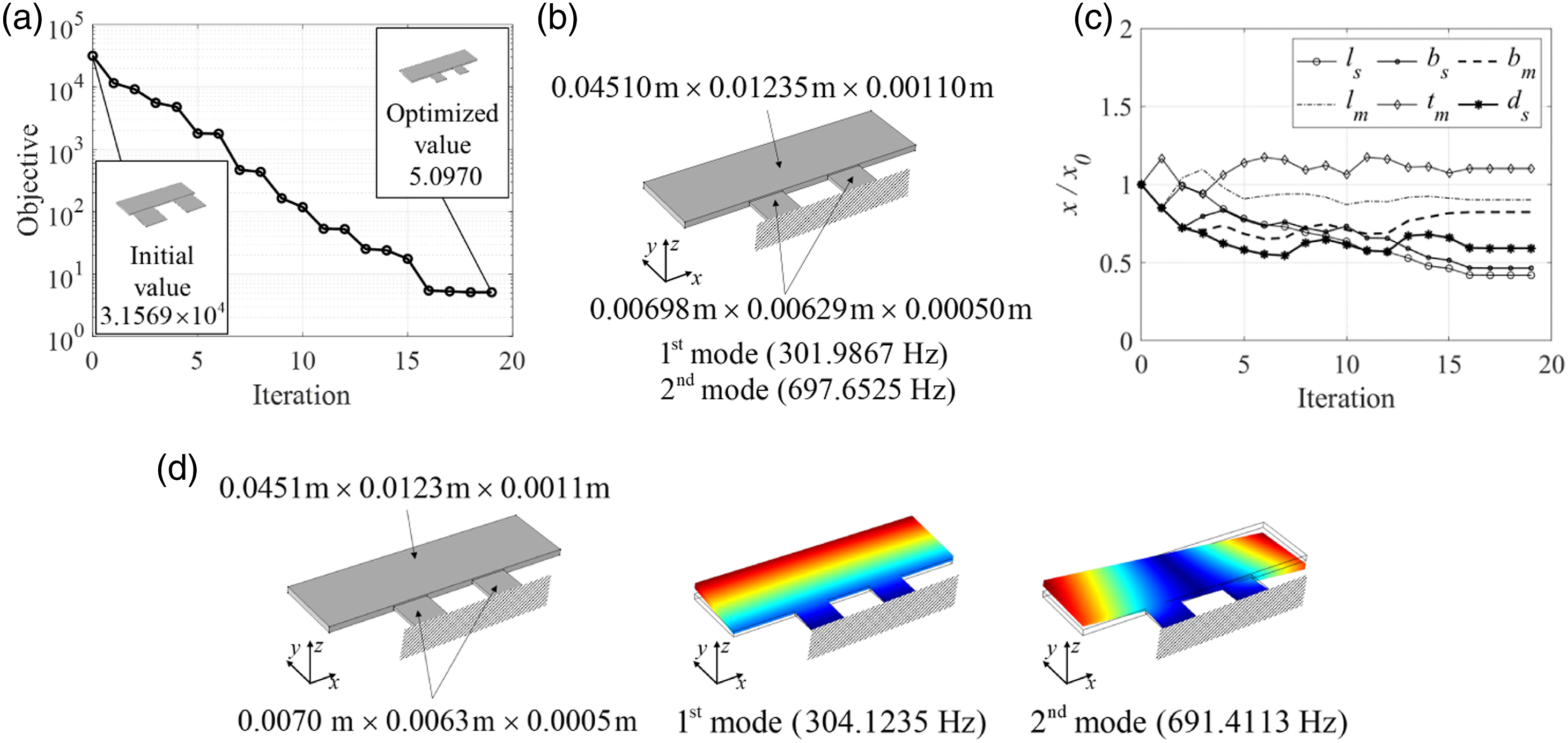
Comparison of the absorption coefficient with and without Dynamic vibration absorber.
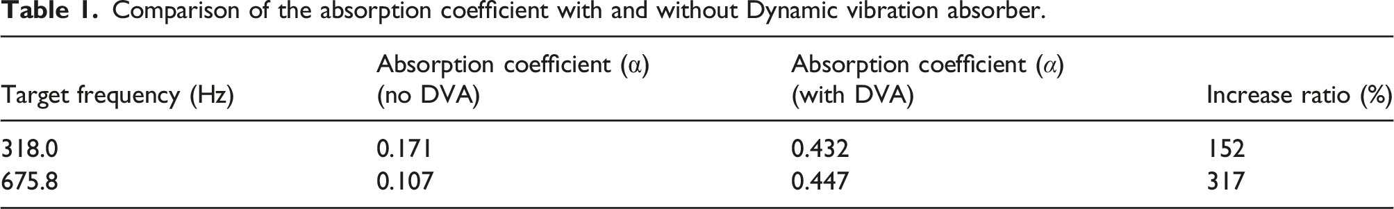
Based on the optimized design, a DVA was manufactured and attached to the circular plate, as shown in Figure 7(a). The values of the sound absorption coefficient for the circular plate with the DVA were measured using an impedance tube, and the responses are plotted in Figure 7(b). As expected, the values of the absorption coefficient improved at the target frequencies of interest. The measured peaks appeared at 318 Hz and 675.8 Hz. The values of the sound absorption coefficient at the peak values increased by 152.2743% and 317.3748%, respectively. These results demonstrate that the sound absorption coefficients can be improved using the optimized DVA. Experimental results at 300 Hz and 700 Hz: (a) circular plate with the optimized Dynamic vibration absorber and (b) comparison of results for the circular plate with and without the DVA. The differences between the eigenfrequencies of the optimized and manufactured DVAs are 5.3027% and 3.1323% for 300 Hz and 700 Hz, respectively.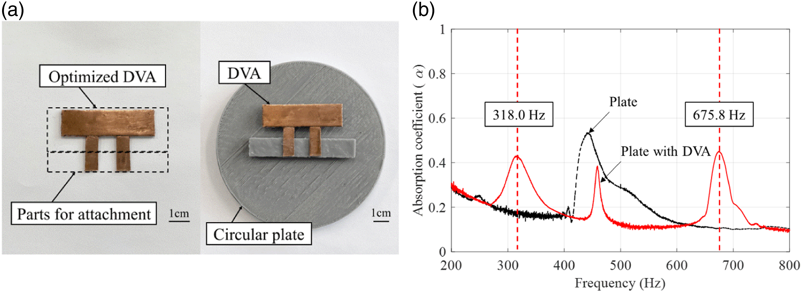
Optimization of DVA at three frequencies
As a second case study, the DVA was optimized to improve the values of the sound absorption coefficients for an identical circular plate at three target frequency values. The sound absorption coefficients of the circular plate are presented in Figure 5 (b). The maximized value of the sound absorption coefficient is determined by the eigenvalue of the circular plate.
39
This case aimed to design a DVA with eigenfrequencies of 300 Hz, 700 Hz, and 900 Hz. Attaching the DVA to the circular plate enabled the circular plate to achieve better sound absorption performances at 300 Hz, 700 Hz, and 900 Hz; the target frequency values were arbitrarily chosen. To achieve the desired optimization, the following optimization formulation was considered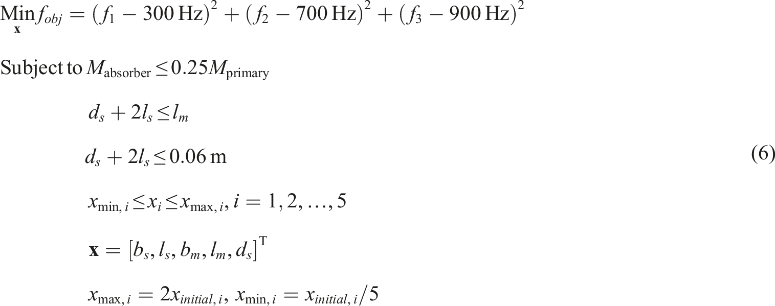
The optimization formulation was slightly modified from that used in the first case study (for two frequencies); the objective function was modified to consider the third frequency value. For simplicity, the number of design variables was reduced to five by fixing t
m
at 0.0005 m. Moreover, the upper and lower bounds of the design variables were set to two times and one-fifth of the initial values of the design variables, respectively. An identical brass plate with a thickness of 0.0005 m was prepared; thus, t
s
was set to 0.0005 m. Because the optimization process involved convergence of the objective function, presented in Figure 8(a), it was possible to realize the design illustrated in Figure 8(b). The detailed convergence of the design variables is illustrated in Figure 8(c). Optimization of the Dynamic vibration absorber at 300 Hz, 700 Hz, and 900 Hz: (a) optimization history; (b) optimized layout; (c) design variable evolution; and (d) post-processed design for manufacturing. The differences between the eigenfrequencies of the optimized and post-processed DVAs are 4.3085%, 5.1359% and 1.2502% for 300 Hz, 700 Hz, and 900 Hz, respectively.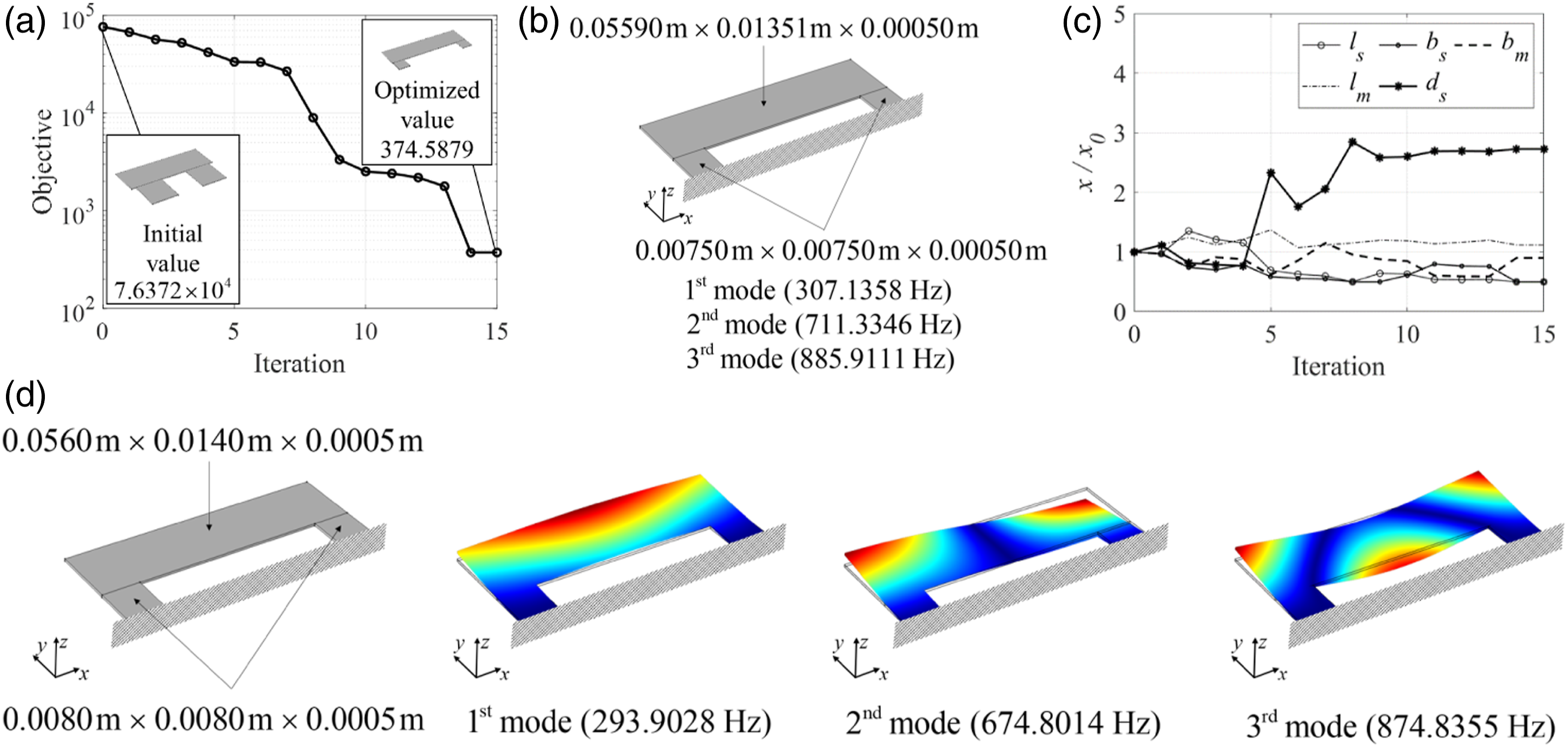
The optimized layout had eigenfrequency values of 307.1358 Hz, 711.3346 Hz, and 885.9111 Hz, which were close to the target frequencies from an engineering perspective. From a practical point of view, post-processing was performed, as illustrated in Figure 6(d), by rounding the values up to five decimal places. Consequently, the frequencies were changed to 293.9028, 674.8014, and 874.8355 Hz. The first, second, and third modes of the optimized design are presented in Figure 8(d). Compared to the design of two frequencies, in this case study, the width between the two supporting structures became wider, and the structure playing the role of mass became larger. The frequencies of the second and third modes differed slightly from the target frequencies by approximately 30 Hz. Although this aspect raises questions regarding the existence of a global optimum design whose frequencies are sufficiently close to the target frequencies from an engineering point of view, the present research accepts these local optima.
Based on the optimized design, the DVA was manufactured and attached to the circular plate, as shown in Figure 9(a). The values of the sound absorption coefficient for the circular plate with the DVA were measured using the impedance tube, and the responses are plotted in Figure 9(b). Note that the values of the sound absorption coefficient were improved at the target frequencies of interest. The measured peaks appeared at 312 Hz, 681 Hz, and 884.8 Hz. The peak values of the sound absorption coefficient increased by 124.1297%, 81.6309%, and 341.1410%, respectively. These results indicate that the frequencies of the proposed DVA can be optimized and that the sound absorption coefficients can be improved by optimizing the DVA Table 2. Experimental results at 300 Hz, 700 Hz, and 900 Hz: (a) circular plate with the optimized Dynamic vibration absorber and (b) comparison of results for the circular plate with and without the DVA. The differences between the eigenfrequencies of the optimized and manufactured DVAs are 1.5837%, 4.2645% and 0.1254% for 300 Hz, 700 Hz, and 900 Hz, respectively. Comparison of the absorption coefficient with and without dynamic vibration absorber.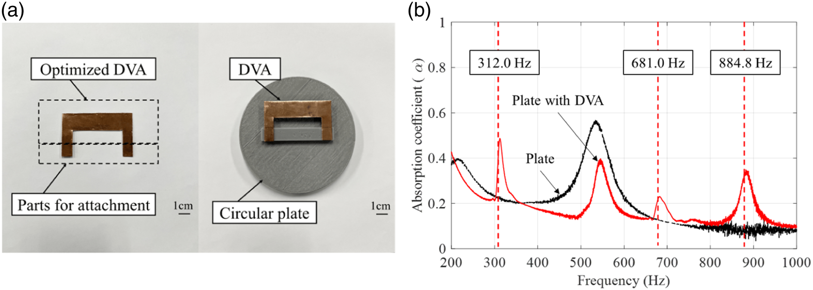
Example 2 Reduction of the transmitted sound considering acoustic-structure interaction
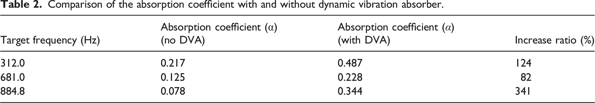
For the next example, a DVA structure was designed to reduce the SPL in a vibro-acoustic system. When a structure is impacted, it vibrates and generates noise. The generated noise contains the vibration modes of the structure, that is, the acoustic-structure interactions. By utilizing the suggested DVA, noise reduction from a rectangular plate is possible. To verify the effects of applying the DVA, a rectangular plate was manufactured, as shown in Figure 10(a). The SPL of the rectangular plate under impact is presented in Figure 10(b). The experimental setup is illustrated in Figure 11. The optimization formulation for the present example is as follows:
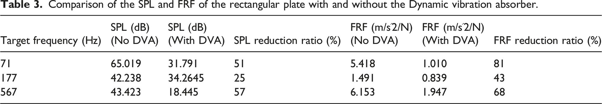
The optimization formulation was slightly modified from that used for the circular plate. The objective function was modified to consider frequency values of 71 Hz, 177 Hz, and 567 Hz. The three target frequencies are determined by the measurements of the structure eigenfrequencies. The first and second constraints were identically imposed to consider the mass ratio and maintenance of the configuration. The third constraint was modified by considering the change in the length of the connecting part. As in the second case study of the first example, five design variables were optimized, and their initial values were set to (0.1000 m, 0.0400 m, 0.0400 m, 0.1000 m, 0.0200 m). The upper and lower bounds of the design variables were set to five times and one-fifth of their initial values, respectively. Because a brass plate of 0.0005 m was considered in this example, t s and t m were set to 0.0005 m. Because the optimization process involved convergence of the objective function illustrated in Figure 12(a), it was possible to obtain the design presented in Figure 12(b). The detailed convergence of the design variables is illustrated in Figure 12(c). The optimized layout had eigenfrequency values of 70.4679 Hz, 180.4822 Hz, and 565.0612 Hz. For manufacturing, post-processing was performed by rounding the design variable values up to five decimal places, as presented in Figure 12(d). Consequently, the frequencies were slightly changed to 69.9990 Hz, 181.8145 Hz, and 559.8805 Hz. The first, second, and third modes of the optimized design are illustrated in Figure 12(d). Based on the optimized design, the DVA was manufactured and attached to the plate, as shown in Figure 13(a). The values of SPL and FRF for the rectangular plate with DVA are plotted in Figures 13(b) and (c), respectively. Both the SPL and FRF graphs exhibit similar peak frequency values, indicating that the acoustic-structure interaction is well considered in this example. The reduction ratios of SPL and FRF are presented in Table 3. These results indicate that the values of FRF and SPL can be lowered using the optimized DVA.
Structure-borne noise experiment for SPL: (a) impact experiment with a rectangular plate and (b) impact SPL of the rectangular plate.
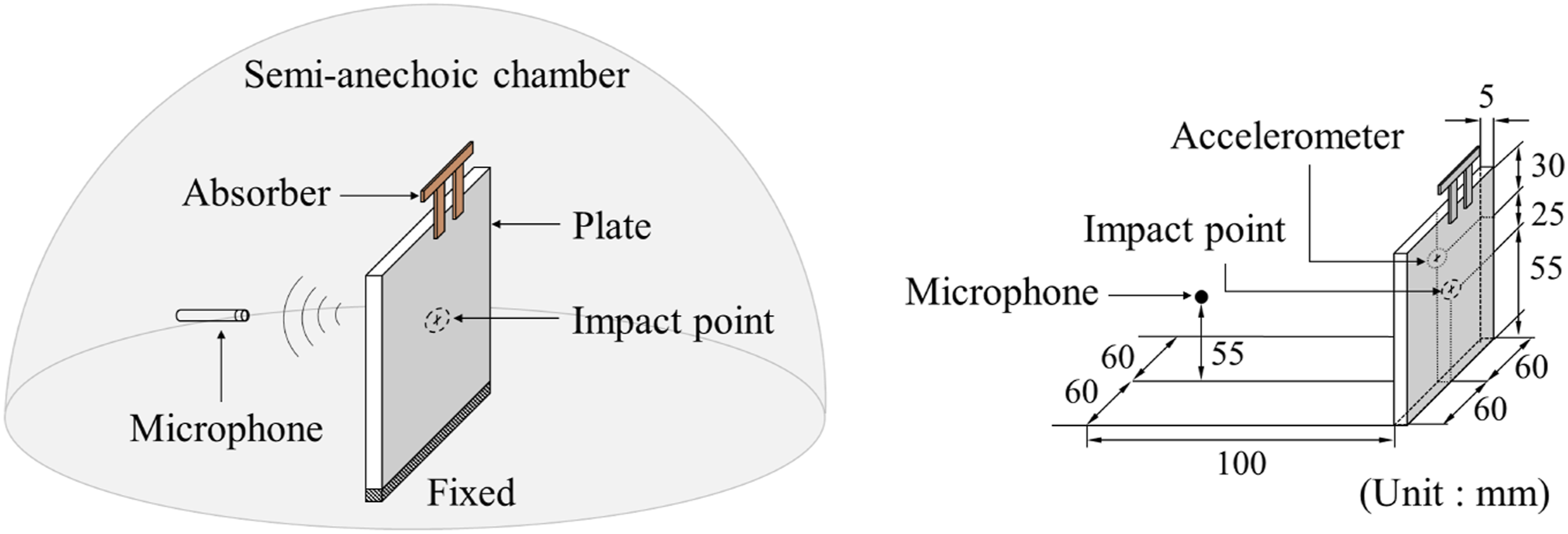
Experimental schematic for a rectangular plate with the dynamic vibration absorber.
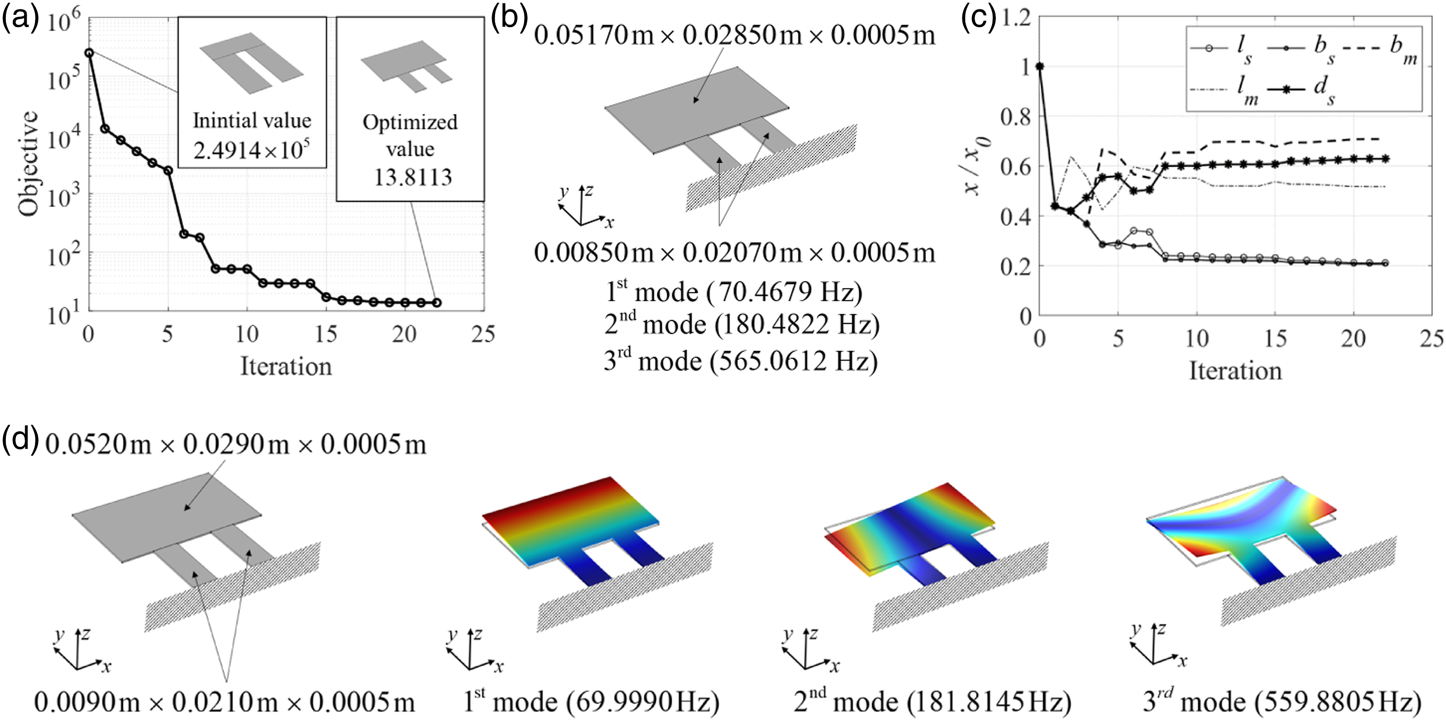
Optimization of the Dynamic vibration absorber at 71 Hz, 177 Hz and 567 Hz: (a) optimization history; (b) optimized layout; (c) design variable evolution; and (d) post-processed design for manufacturing. The differences between the eigenfrequencies of the optimized and post-processed DVAs are 1.2610%, 0.6899%, and 0.3598% for 71 Hz, 177 Hz, and 567 Hz, respectively.
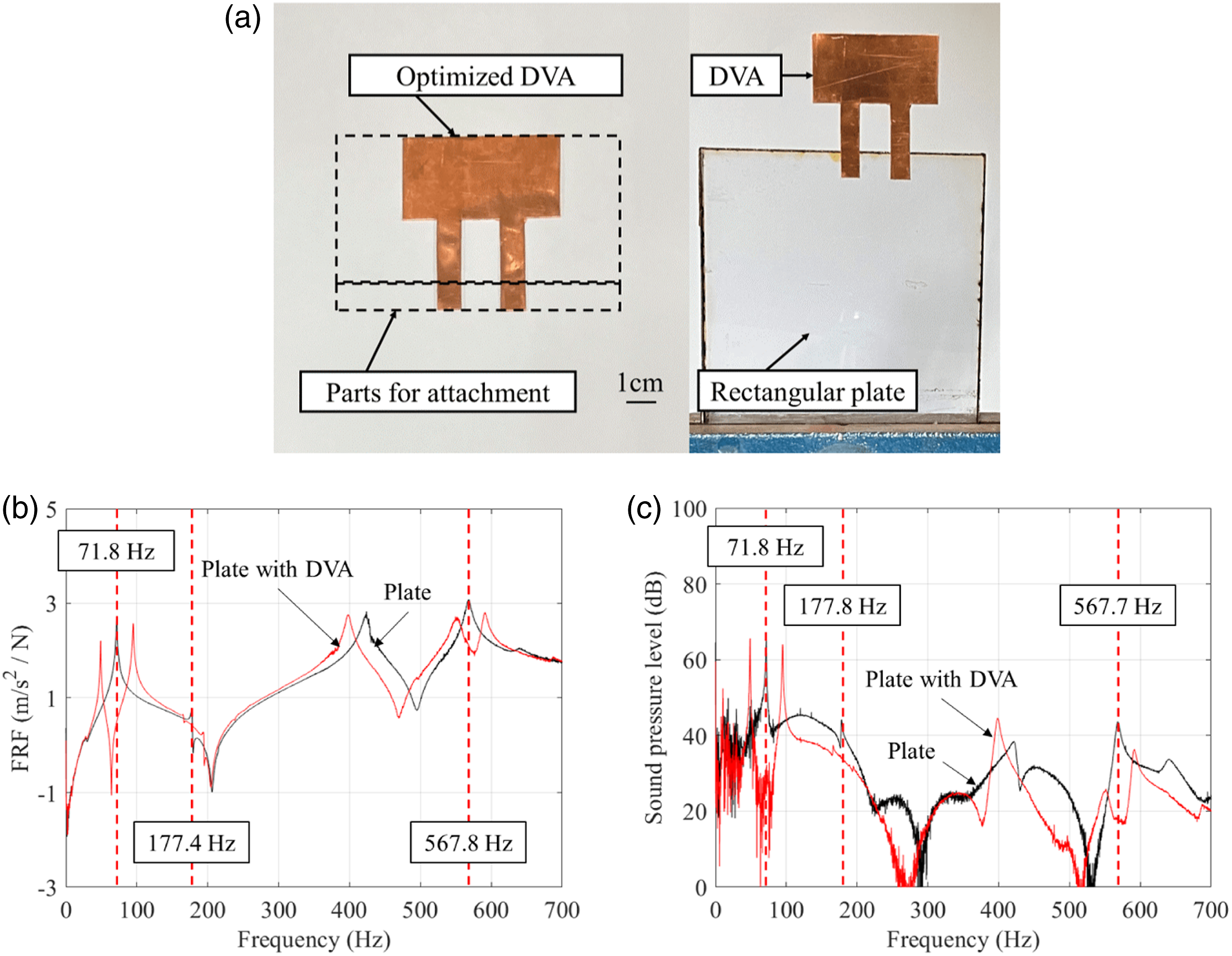
Experimental results of the rectangular plate at 71 Hz, 177 Hz, and 567 Hz: (a) with the optimized Dynamic vibration absorber; (b) SPL with and without the optimized DVA; and (c) FRF with and without the optimized DVA.
Comparison of the SPL and FRF of the rectangular plate with and without the Dynamic vibration absorber.
Example 3 Reduction of the transmitted sound of the bottomless box with several surfaces
As a third example, a DVA structure was designed to reduce the sound radiation of a vibro-acoustic system, as illustrated in Figure 14(a) and 15(a). With a mechanical impact force, the structure vibrates and generates noise owing to acoustic-structure interaction. The SPL in Figure 14(b) exhibits multiple resonance peaks owing to resonance. In this example, the positions of the microphone and impact were fixed, as shown in Figure 18(a). The optimization problem is formulated as follows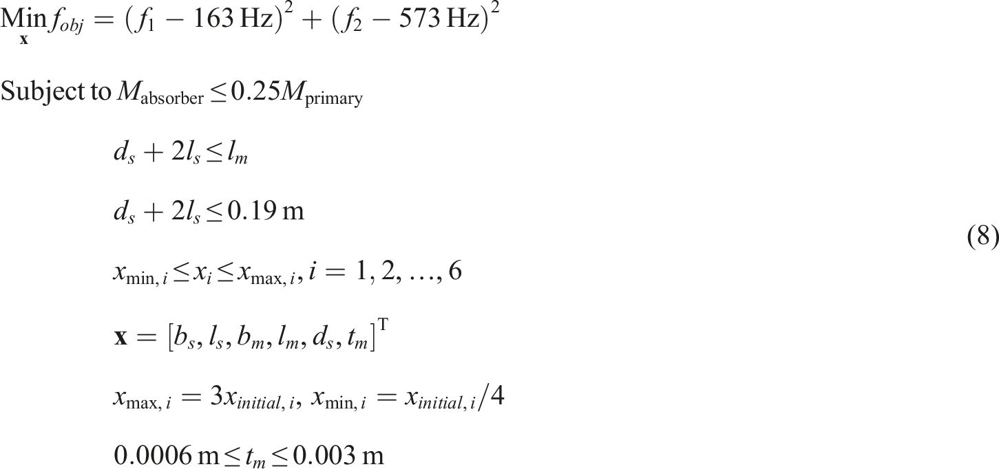
The optimization formulation was similar to that used for the circular and rectangular plates. The two target frequencies are determined by the measurements of the structure eigenfrequencies. The objective function was modified to consider the frequency values of 163 Hz and 574 Hz, which displayed the highest SPL values at a fixed microphone position. The first and second constraints were established to consider the mass ratio and maintenance of the DVA configuration. The third constraint was modified by considering the change in the length of the connecting part. Identical to the first case study of the circular plate, six design variables were considered, and their initial values were set to (0.0500 m, 0.0300 m, 0.0500 m, 0.0700 m, 0.0100 m, 0.0010 m). Except for t s , the upper and lower bounds of the design variables were set to three times and one-fourth of the initial values of the design variables, respectively. For t m , the upper and lower bounds were set as 0.003 m and 0.0006 m, respectively. A brass plate of 0.0006 m was considered for this example; thus, t s was set to 0.0006 m. Because the optimization process involved convergence of the objective function illustrated in Figure 16(a), it was possible to realize the design presented in Figure 16(b). The detailed convergence of the design variables is illustrated in Figure 16(c). The optimized layout had eigenfrequency values of 163.3967 Hz and 578.7101 Hz, which were close to the target frequencies from an engineering perspective. From a practical point of view, post-processing was performed, as illustrated in Figure 16(d), by rounding the design variable values up to five decimal places. Consequently, the frequencies were changed to 162.8574 Hz and 578.2572 Hz, respectively; these values were sufficiently close from an engineering point of view. The modes of the optimized design are presented in Figure 16(d).
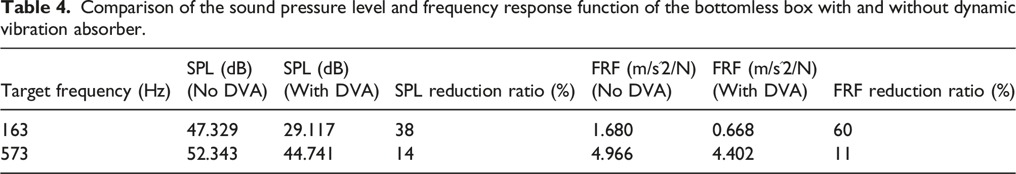
Figure 17 illustrates the FRF results used to determine the positions of the DVAs. As the opposite sides of the bottomless box are symmetrical, accelerometers were attached to the center of the three sides to compare the values of the amplitudes of FRF. The FRF curve obtained from point 2 is smaller than the curves obtained from points 1 and 3. Thus, the manufactured DVAs were attached to points 1 and 3 of the bottomless box. The SPL and FRF for the bottomless box with DVAs are presented in Figures 18(a) and (b), respectively. Both the SPL and FRF graphs exhibited identical peak frequency values, indicating that the acoustic-structure interaction was well implemented. The reduction ratios of the SPL and FRF are presented in Table 4. These results indicate that a DVA can be optimized and that multiple DVAs can be utilized to reduce both the SPL and FRF of bottomless box structures, which are employed in various acoustic-related engineering problems.
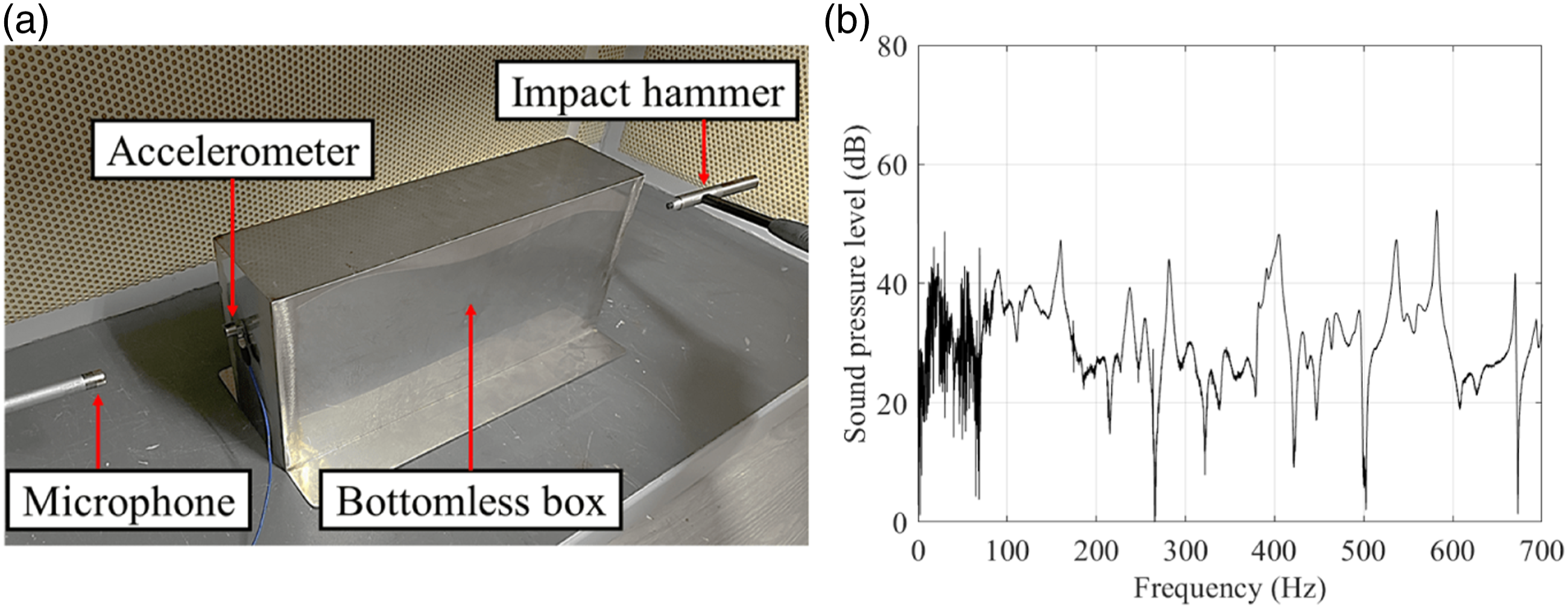
Structure-borne noise experiment for a bottomless box: (a) structure-borne noise from the impact and (b) SPL from the impact.
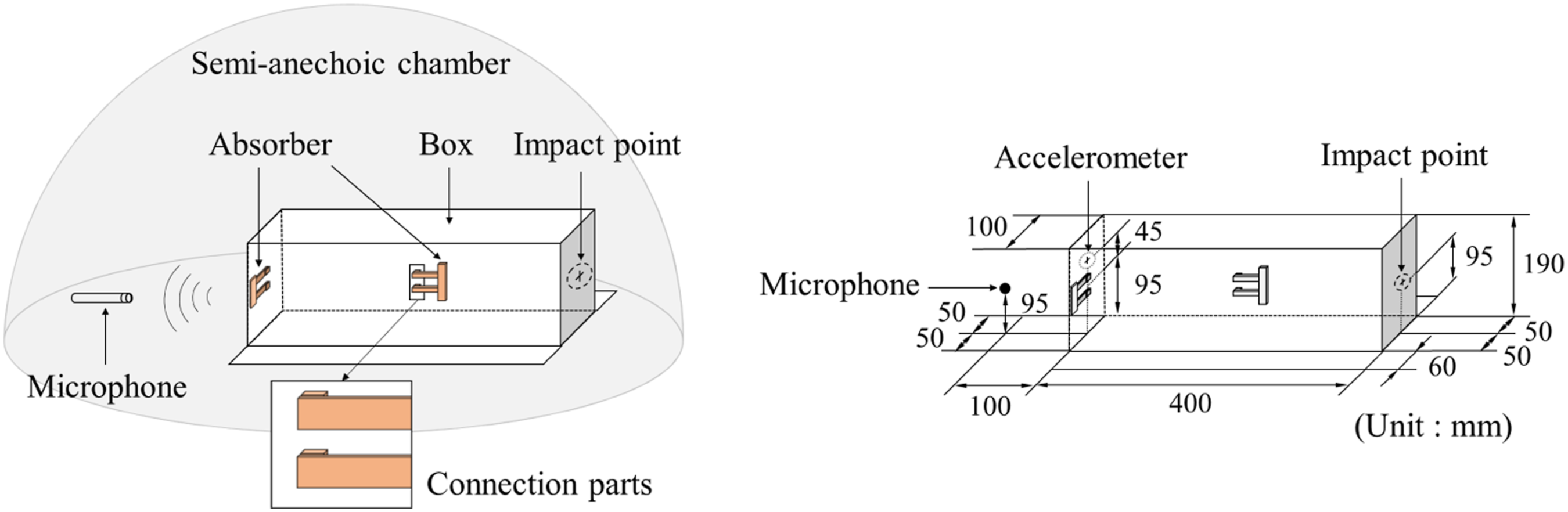
Experimental schematic for the bottomless box with dynamic vibration absorbers.
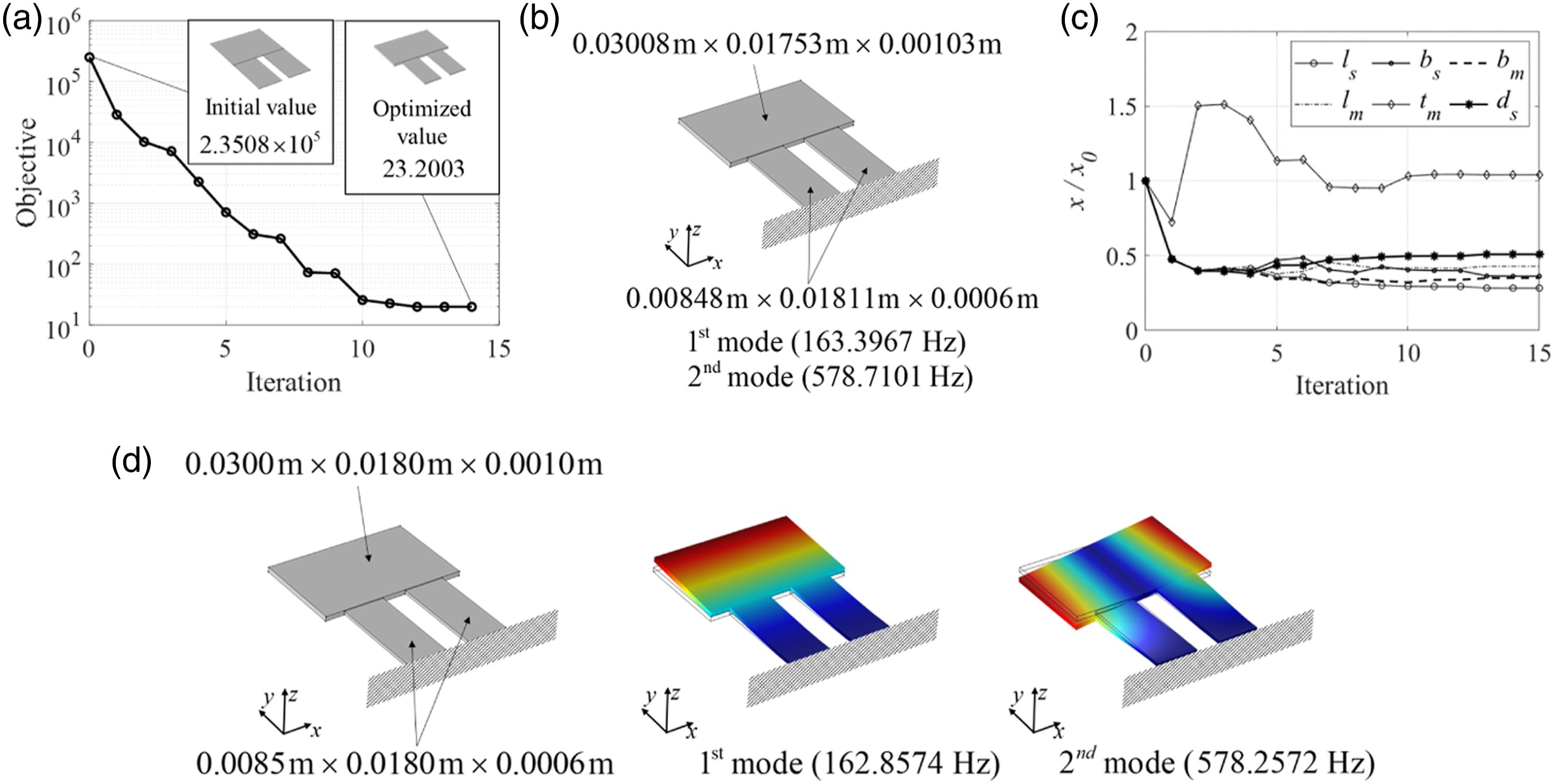
Optimization of the optimized dynamic vibration absorber at 163 Hz and 573 Hz: (a) optimization history; (b) optimized layout; (c) design variable evolution; and (d) post-processed design for manufacturing. The differences between the eigenfrequencies of the optimized and post-processed DVAs are 0.9966% and 0.9992% for 163 and 573 Hz, respectively.
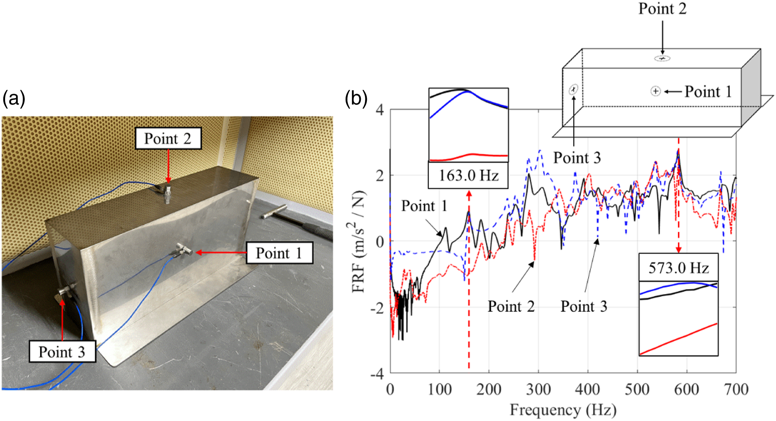
Frequency response function measurements to determine the positions of DVAs: (a) points of the accelerometers and (b) FRF at three different points in the bottomless box experiment.
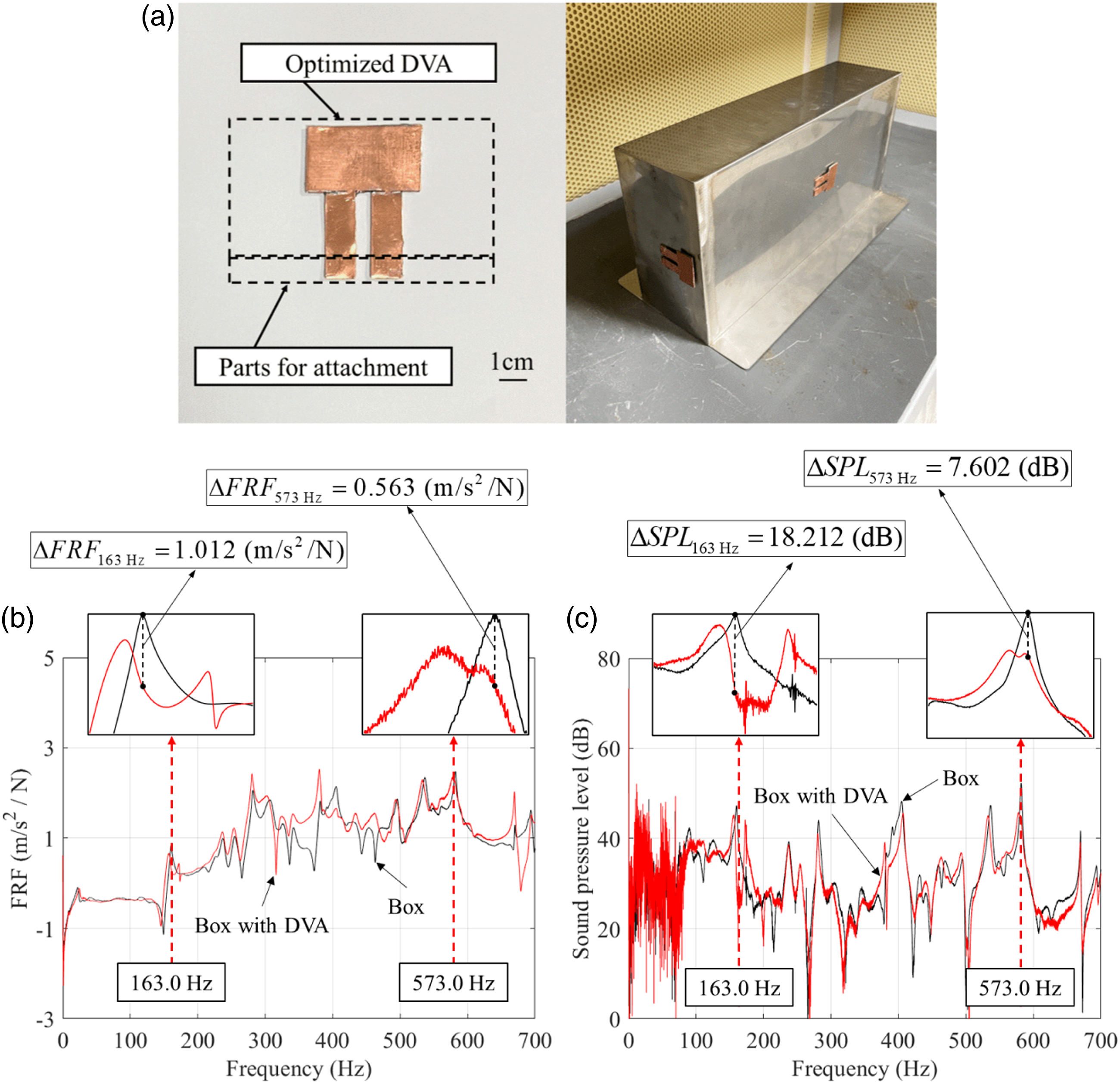
Experimental results of the bottomless box at 163 Hz and 573 Hz: (a) with the optimized dynamic vibration absorber; (b) sound pressure level with and without the DVA; and (c) frequency response function with and without the DVA.
Comparison of the sound pressure level and frequency response function of the bottomless box with and without dynamic vibration absorber.
Discussion and conclusion
It is an important subject to suppress irritating vibrations and noises. This study presents a dynamic vibration absorber that attenuates the vibration and induced noises of structure at multiple frequencies. To tune the first two or three eigenfrequencies of the present DVA, the geometry parameters of the DVA are modified accordingly. However, it is an intricate process to tune the eigenfrequencies by modifying the geometry parameters of the DVA. The determination of the geometry parameters, that is, five or six design variables is done with a gradient-based optimizer. The size optimization of DVA allows the modification of eigenfrequencies close to the target frequencies. Post-processing is done after the optimization procedure for manufacturing of DVA based on the optimization results. The geometric dimensions of the DVA are rounded to 0.1 mm and alterations of eigenfrequencies are observed in this process with maximum value of 5%. Despite these alterations, the reductions of vibrations and noises are still observed at target frequencies. After manufacturing DVAs, experiments considering impedance tube and impact hammer are conducted to confirm validity. The values of sound absorption coefficient are measured and analyzed in the impedance tube experiments. With the effects of the DVA, it is possible to get increased sound absorption coefficients at target frequencies. In the impedance tube experiment at the first case, the values of sound absorption coefficient are approximately increased 152% and 317% at frequencies of peak values respectively. In the impedance tube experiment at the second case, the values of sound absorption coefficient are approximately increased 124%, 82% and 317% at frequencies of peak values respectively. The values of SPL and vibration response are measured and analyzed in the impact hammer experiments. In the impact experiment considering rectangular plate, the values of FRF and SPL are approximately attenuated by 81% and 51% in the first mode, 43% and 25% in the second mode, 68% and 57% in the fourth mode of the rectangular plate, respectively. In the impact experiment of the bottomless box, the values of FRF and SPL are approximately attenuated by 60% and 38% in the first targeted frequency, 11% and 14% in the second targeted frequency, respectively. We can obtain the high repeatability for the first example improving the sound absorption coefficient of a circular plate with DVA and the second example decreasing the sound pressure level and the vibration of a rectangular plate with fixed boundary condition. In the third example, the performance of DVA for a bottomless box is tested. In this example, the contact condition of the box significantly influences the experiment results. It is observed that the in-plane vibrations orthogonal to the direction of gravity and the associated sound propagation are sensitivity to the contact condition. In addition, due to the rigidity of the corners, the vibration modes became perplex and it is difficult to install the two DVAs in proper locations and obtain the consistent experiment results. Therefore, the two DVAs are manufactured with a high precision and the two locations are chosen by trial and error.
The benefits of the present DVAs lie in the fact that they can reduce vibrations of hosting structures at multiple frequencies by utilizing their multiple modes. It is also possible easily tune the geometric parameters of the DVAs to adjust wide-band target frequencies. In addition, this research validates through simulations and experiments that the present DVAs can reduce vibration and structure-borne sound simultaneously. It is observed that the performance in terms of vibration and sound absorption is significantly improved at target frequencies of DVA. However, vibration and noise level at other frequencies can be higher due to the law of conservation of energy. One of the novelties of the present study lies in the fact that with optimized DVA, it is possible to consider the vibrations and noises at multiple target frequencies. The performance of the optimized DVA is verified considering the acoustic-structure interaction. For future research topic, it may be possible to optimize the design variables considering the manufacturing process and the robustness. It also may be possible to optimize DVA location which is the place to reduce the sound pressure.
Footnotes
Declaration of conflicting interests
The author(s) declared no potential conflicts of interest with respect to the research, authorship, and/or publication of this article.
Funding
This work was supported by the National Research Foundation of Korea (NRF) grant funded by the Korea government (MSIT) (No.2018R1A5A7025522).