
Abstract
In order to reduce the natural frequency of the piezoelectric vibration energy harvester, improve the output power of the piezoelectric vibration energy harvester, and meet the demand of power supply for the low-power wireless switch in the low-frequency vibration environment, an asymmetric hybrid supported beam piezoelectric vibration energy harvester is proposed. The theoretical model of the hybrid support beam was established. The correlation factors affecting the open-circuit voltage and the total output power of the hybrid braced beam were analyzed. The dimensional parameters of the hybrid supported beam piezoelectric energy harvester were optimized by using the optimization method of orthogonal experiments. Different coincidence degrees experiments were used to further optimize the structural design of the hybrid support beam. The test results show that the maximum output power is 770 μW, when the external excitation frequency is 1.0 g and the external resistance is 50 kΩ. Finally, a wireless switch test system was established, and the piezoelectric vibration energy harvester was experimentally verified to be capable of powering the wireless switch.
Introduction
With the continuous development of wireless switch technology, both wireless switch network and Internet of Things technology, with wireless switch as the core component, have been highly developed and widely used in academic and industrial fields, while the development of wireless switch low-power technology is the power source to promote relevant development.1–2 At present, the wireless switch is still powered by the traditional chemical battery, but the traditional chemical battery power supply is limited in service life, large volume, difficult to replace in harsh environments and other shortcomings, which limit the application of chemical battery.3–5 The idea of converting vibration energy widely existing in the environment into electric energy has been proposed by many scholars.6–8 According to the different energy conversion mechanisms, it can be divided into piezoelectric type, electrostatic type and electromagnetic induction type. Due to the advantages of piezoelectric type, such as simple structure, high energy density and small heat generation, piezoelectric type has become a research hotspot.
At present, the more mature piezoelectric energy harvesting structure is the classical rectangular cantilever beam structure,9–11 but this structure has the disadvantages of high natural frequency and low output energy during energy harvesting. To improve the above problems, Liu Yanbin 12 studied an equal strength beam type piezoelectric vibration energy harvesting structure. Compared with the traditional equal section piezoelectric vibration energy harvesting structure, the proposed structure can effectively reduce the natural frequency of energy harvesting and increase the energy output. However, the fabrication of equable-strength beam is not convenient, and the toughness of the structure decreases. Xiao et al. 13 proposed a vibration energy harvesting structure composed of a piezoelectric disk and four mass blocks. This structure can effectively improve the energy output in the high frequency range, but the device’s own weight is large and the natural frequency of energy harvesting is high. Wang Hai et al. 14 proposed a multi-mass piezoelectric energy harvesting structure, whose first-order natural frequency reached the lowest 28 Hz and the maximum output power reached 31 mW. However, with the increase of mass blocks, the piezoelectric ceramics were prone to fracture and the stability of the piezoelectric energy harvesting system was reduced. Sun et al. 15 proposed a horizontal asymmetric U-shaped vibration energy harvesting structure, which can effectively reduce the natural frequency obtained during energy harvesting. Although this structure is relatively complex and prone to electromagnetic interference during energy harvesting, the asymmetric structure opens up a new research idea for energy harvesting. Yang 16 et al. proposed a vibration energy harvesting structure of circular piezoelectric wafer, which can make full use of the utilization rate of piezoelectric materials and improve the output power of the energy harvesting structure. However, the circular piezoelectric wafer is not only difficult to make but also easy to be damaged.
The traditional piezoelectric vibration energy harvester has the limitations of high natural frequency and low output performance in the energy harvesting process. In order to improve the above deficiencies and meet the power supply requirements of low-power wireless switches used in low-frequency vibration environments, an asymmetric hybrid supported beam piezoelectric vibration energy harvester is proposed in this paper. This harvester changes the traditional cantilever beam type to a hybrid support beam type with the left end supported by the peripheral fixed hinge and the right end supported by the living hinge, and changes the traditional completely overlapping upper and lower piezoelectric ceramic plate structure into an incompletely overlapping upper and lower piezoelectric ceramic plate structure. In this paper, the method of orthogonal analysis is used to optimize the parameters of the piezoelectric energy harvester, which greatly reduces the number of analysis and improves the optimization efficiency. The energy output characteristics under different connection methods and overlapping degrees of piezoelectric ceramic plates are analyzed, and the optimal matching load of the energy harvester is obtained through analysis, and the experiment of supplying energy to the wireless switch is carried out. It is finally confirmed that the asymmetric hybrid supported beam piezoelectric vibration energy harvester designed in this paper can achieve the purpose of reducing the natural frequency and improving the energy output performance, and can meet the power supply requirements of low-power wireless switches in a low-frequency vibration environment.
Theoretical analysis
In order to theoretically analyze the dynamic characteristics of the hybrid braced beam structure and establish the dynamic model, the following simplifications and assumptions are made: a. The bending deformation of the beam conforms to the assumption of small deformation in the mechanics of materials, and the beam cross-section remains flat and perpendicular to the longitudinal fibers of the beam after deformation. b. Due to the extremely thin thickness of electrodes and colloids, the influence of electrodes and colloids on the mechanical properties of both materials is not considered.
Using the Euler–Bernoulli equation, the dynamic equation of the piezoelectric vibrator shown in Figure 1 can be expressed as Hybrid beam with supports.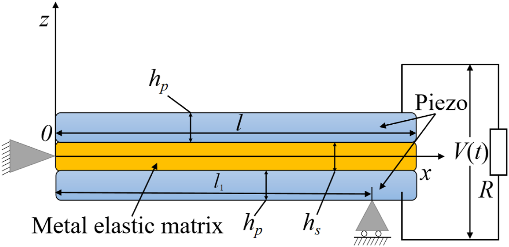

In the formula:
m represents the mass of the beam per unit length. The mass m per unit length is given by

In the formula:

When considering the electromechanical coupling effect, the bending moment is


Under the action of

The hybrid support beam has a perimeter fixed hinge support at the left end and a movable hinge support at the right end.


The hybrid support beam piezoelectric energy collector is analyzed according to electro elastic dynamics. In a load resistor circuit, electrical governing equation derived from the Gauss law20–21 is

In the formula: b,

According to Kirchhoff’s law, it is obtained that

The capacitance of the piezoelectric ceramic in the circuit is

Combining equations (6) and (11), the distributed parameter model of the hybrid support beam piezoelectric vibrator was obtained. As a result, the relative vibration displacement of the piezoelectric beam, the output voltage and the captured power of the system were calculated.
Based on the proportional damping assumption, the relative vibration response of the hybrid support beam can be written in the form of a convergent series of eigenfunctions according to the modal superposition method


For


The mode shapes shown satisfy the orthogonal condition, and then


In the formula:


Under harmonic excitation, the output voltage of the piezoelectric vibrator here should also be in the form of harmonics,

Suppose the stable solution is

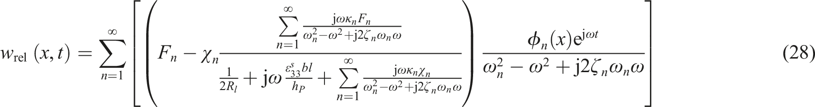
The lateral relative displacement response at any point in the physical coordinates of the hybrid support beam can be obtained as
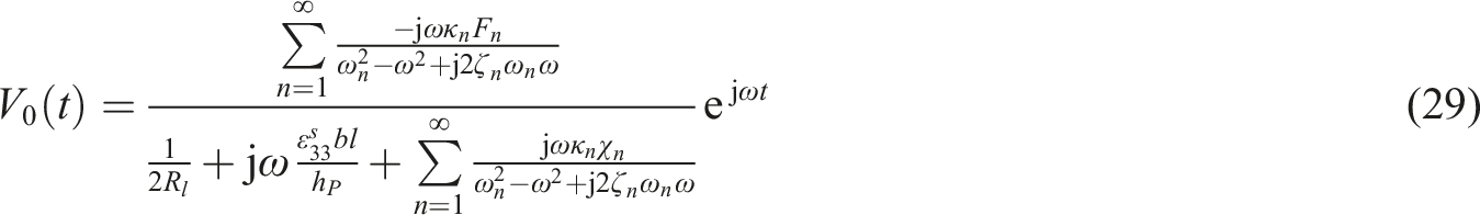
The steady-state voltage response of the piezoelectric energy harvester with the hybrid support beam structure is
The instantaneous output power across the load resistor can be written as
So far, the analytical solution of the distributed parameter model of the hybrid support beam piezoelectric oscillator under harmonic vibration excitation is obtained. From the above analysis, it can be concluded that the piezoelectric ceramic on the piezoelectric energy harvester can be equivalent to a capacitor and a controlled power supply when the energy harvesting is performed by the piezoelectric energy harvester. They are both related to parameters such as the piezoelectric sheet size. And, it can be seen from equation (29) that the size length l, width b and thickness
Structural design and analysis of hybrid support beam
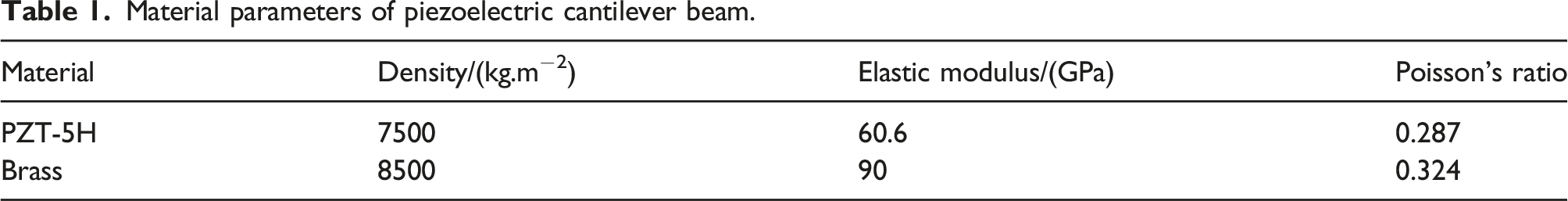
The structures of the four different support methods are shown in Figure 2. The modal analysis and piezoelectric analysis of piezoelectric vibrators of cantilever beam type, peripheral fixed support type, simply supported beam type and hybrid supported beam type are carried out by COMSOL finite element analysis software. Among them, the hybrid support beam is simply supported around one end and simply supported at one end. PZT-5H is selected as the piezoelectric material for the piezoelectric oscillator and brass plate is selected as the elastic substrate. The specific material properties are shown in Table 1. Different support methods of piezoelectric vibrator. Material parameters of piezoelectric cantilever beam.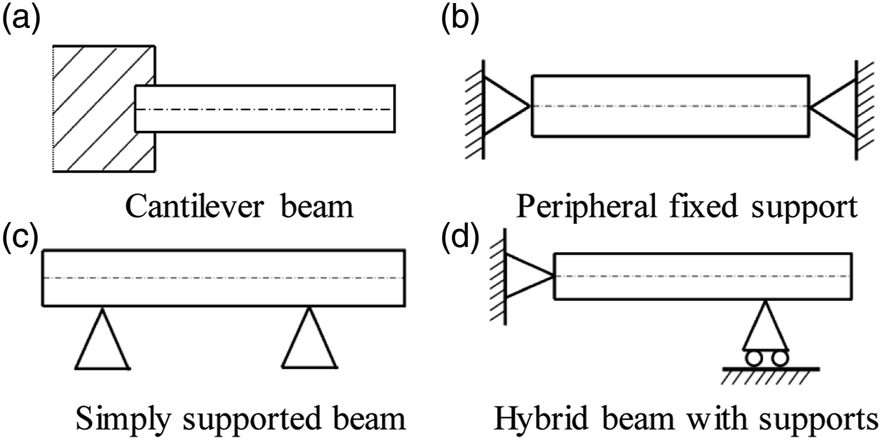
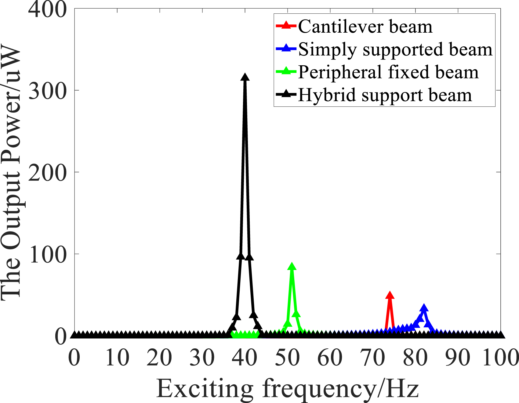
The size of the elastic substrate of the piezoelectric vibrator is 70 mm*10 mm*0.2 mm, and the size of the piezoelectric ceramic sheet is initially set to 40 mm*6 mm*0.2 mm. The distance from the left fixed end of the piezoelectric sheet is 15 mm. The modal analysis results are shown in Figure 3, and the piezoelectric analysis results are shown in Figure 4. Figure 3 is the natural frequency histogram of the piezoelectric vibrators with different support modes. The natural frequencies of cantilever beam type, peripheral fixed beam type, simply supported beam type and hybrid supported beam type are 74.5 Hz, 54.5 Hz, 82.6 Hz and 40.4 Hz. Figure 4 is the output power-frequency curve of the piezoelectric vibrators with different support modes. The output power is respectively 49 μW, 84 μW, 33 μW, 315 μW. From the above, it can be seen that among the four support modes, the hybrid support beam has the lowest intrinsic frequency and the highest output power, so the hybrid support beam piezoelectric vibration energy harvester is chosen as the research object of the energy harvesting structure. Natural frequencies of piezoelectric vibrators with different support methods. Output power-frequency curves of different support methods.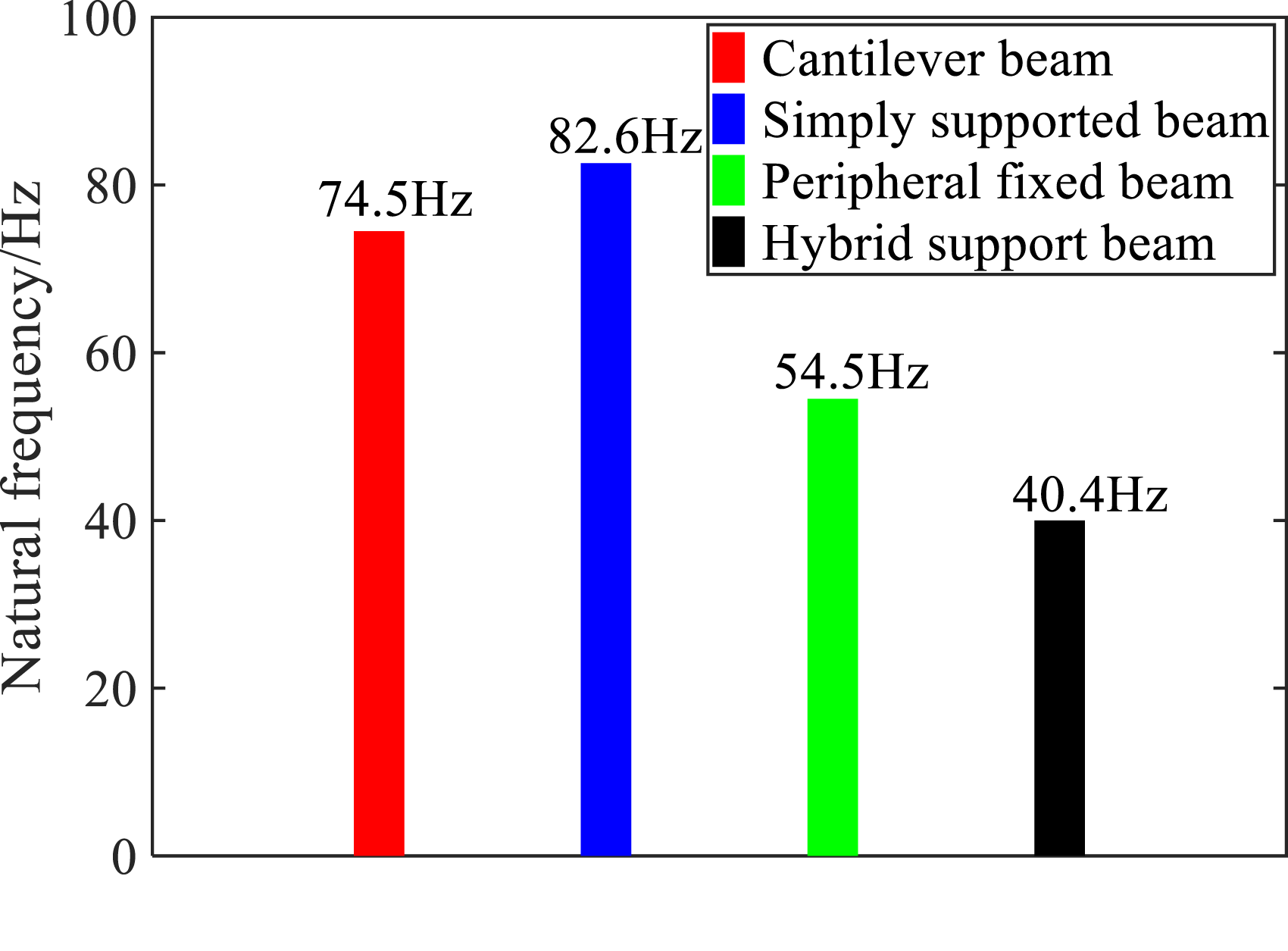
The dimensions of the piezoelectric energy harvesting structure of the hybrid support beam are shown in Figure 5. Wherein, the size of the elastic substrate (length*width*thickness) is 70 mm*10 mm*0.2 mm, and the size of the piezoelectric ceramic sheet (length*width*thickness) is L*W*h. Because the size of the piezoelectric ceramic sheet will affect the natural frequency and output power of the harvesting structure, Therefore, later in this paper, the dimensions of the piezoelectric ceramic plate located at the center of the piezoelectric oscillator are optimized through orthogonal experiments to reduce the intrinsic frequency of the structure and increase the output power of the system. Dimensional drawing of hybrid support beam piezoelectric energy capture structure.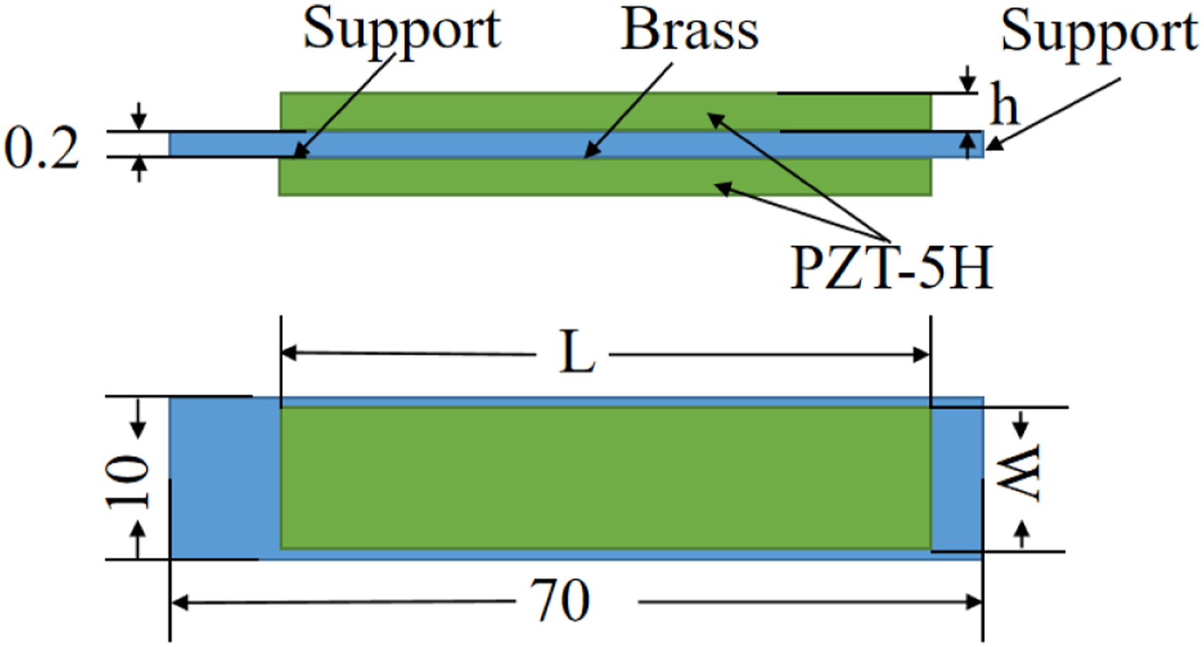
Optimization of dimensional parameters based on orthogonal analysis
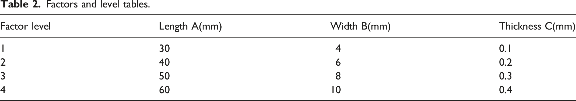
As mentioned above, the length l, width b and thickness
Factors and level tables.
Orthogonal table of natural frequency and output power calculation results.
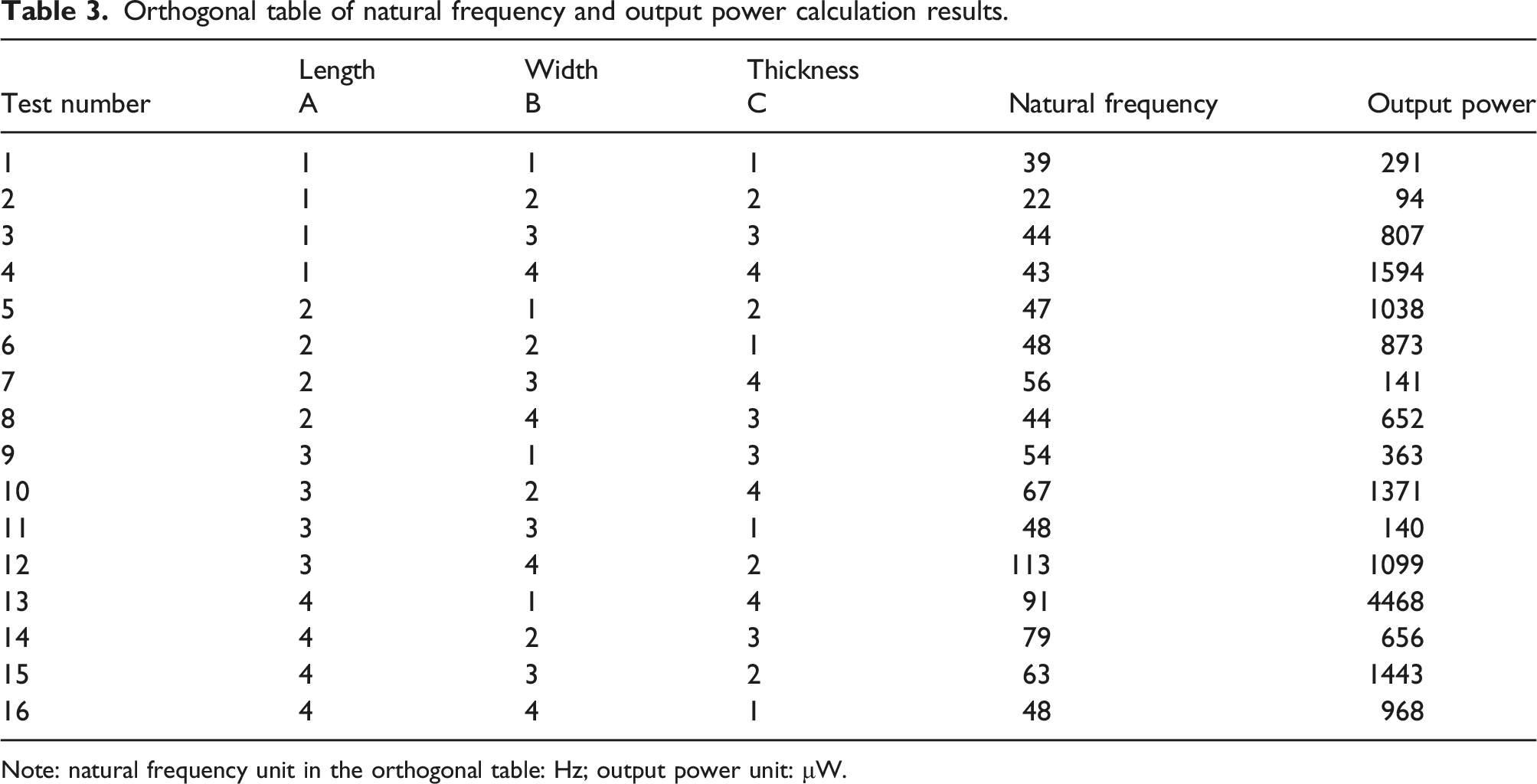
Note: natural frequency unit in the orthogonal table: Hz; output power unit: μW.
Range analysis and results of natural frequency.
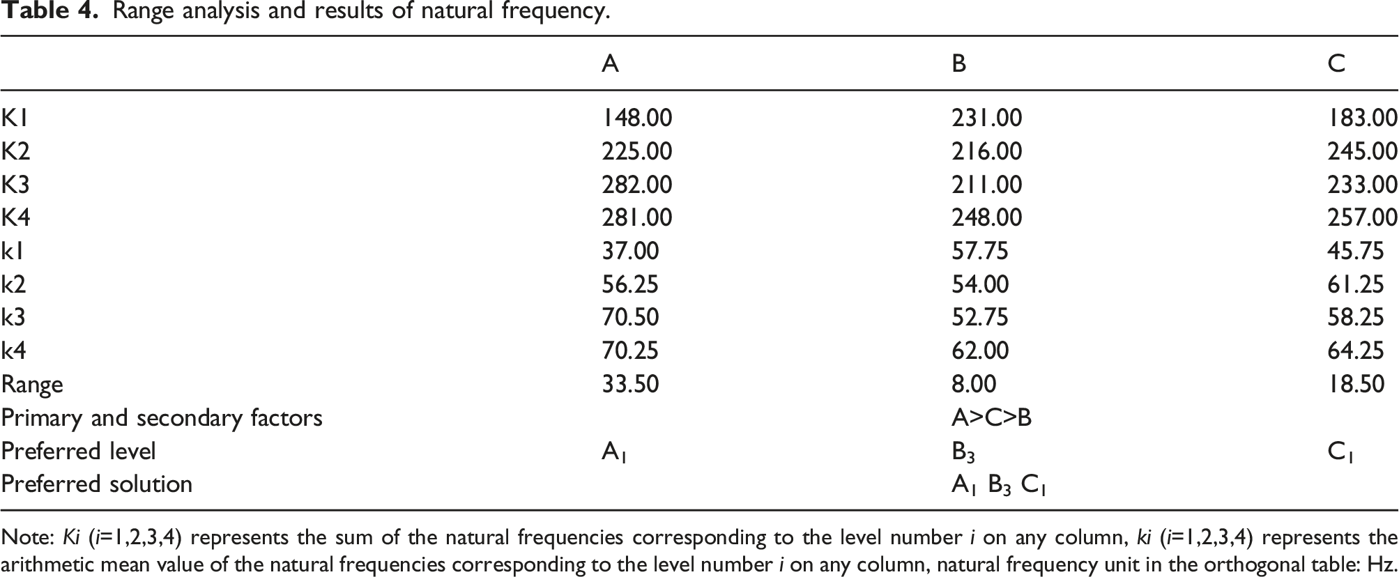
Note: Ki (i=1,2,3,4) represents the sum of the natural frequencies corresponding to the level number i on any column, ki (i=1,2,3,4) represents the arithmetic mean value of the natural frequencies corresponding to the level number i on any column, natural frequency unit in the orthogonal table: Hz.
Analysis of output power range and results.
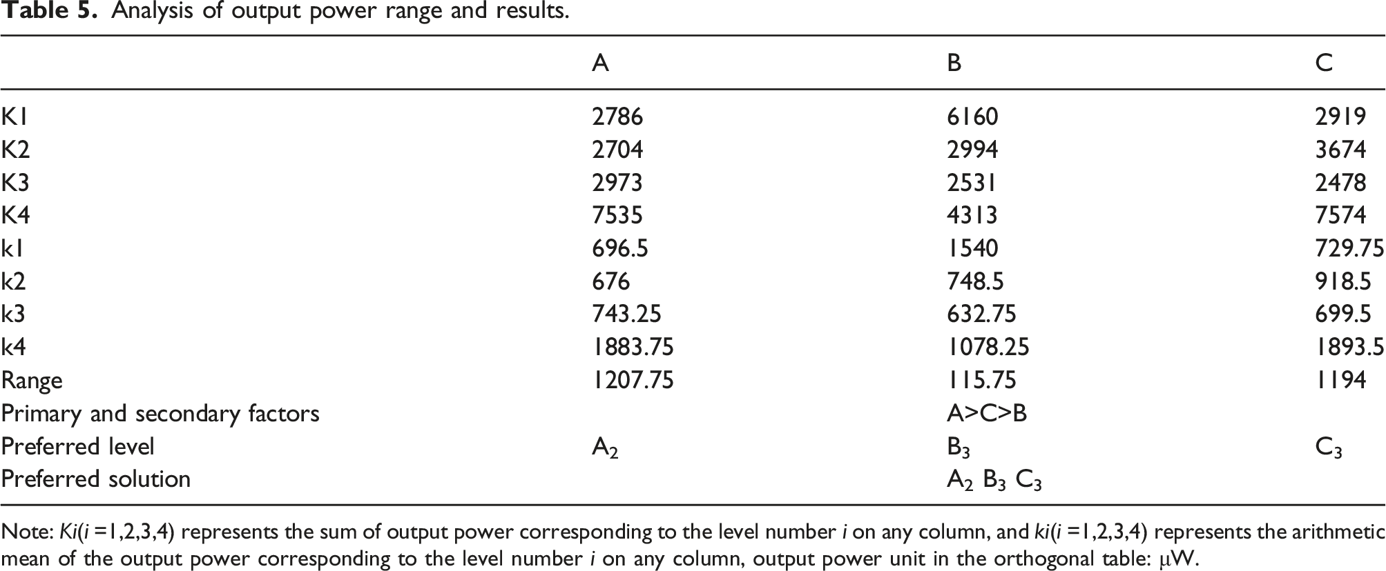
Note: Ki(i =1,2,3,4) represents the sum of output power corresponding to the level number i on any column, and ki(i =1,2,3,4) represents the arithmetic mean of the output power corresponding to the level number i on any column, output power unit in the orthogonal table: μW.
Basic experimental research
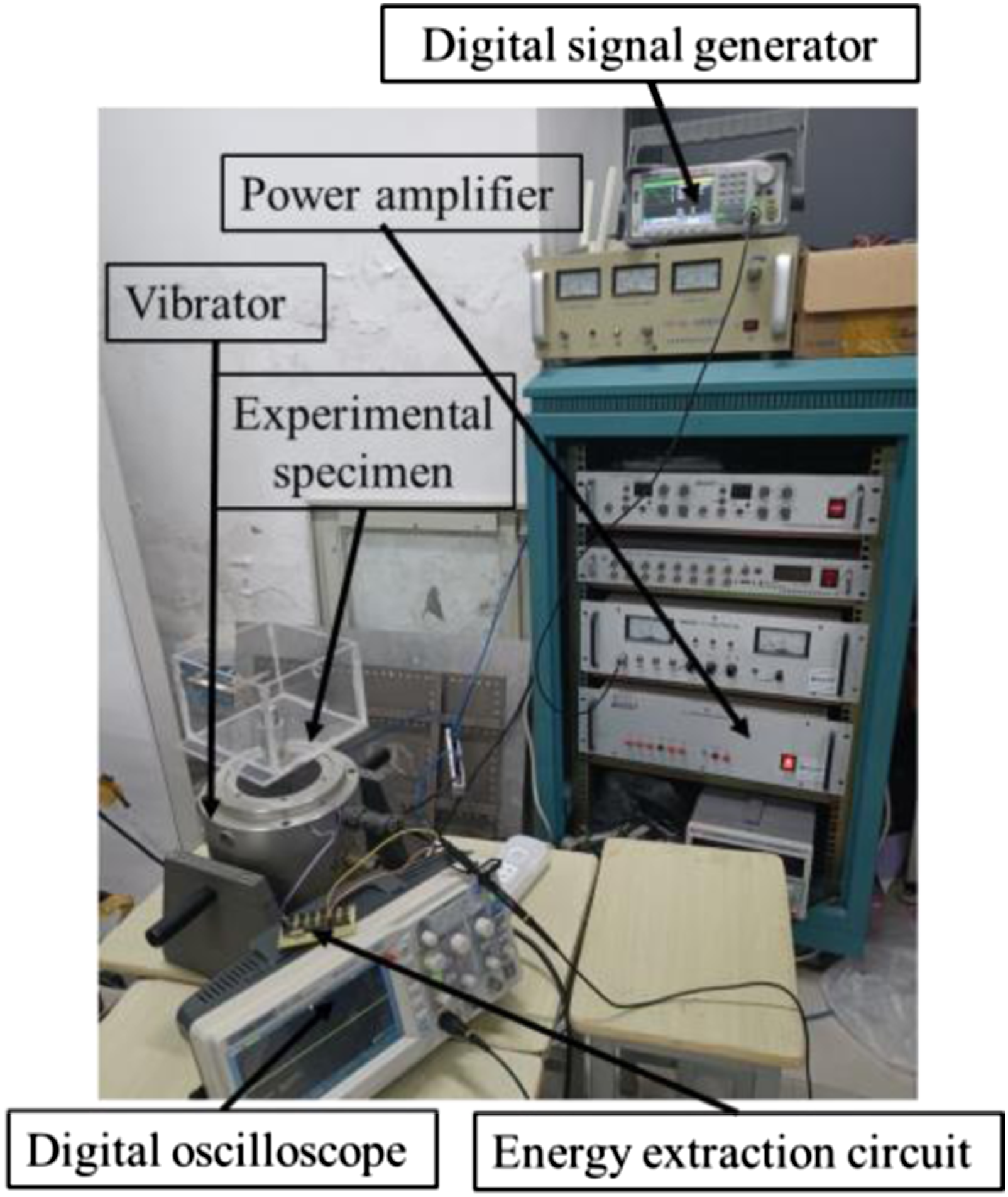
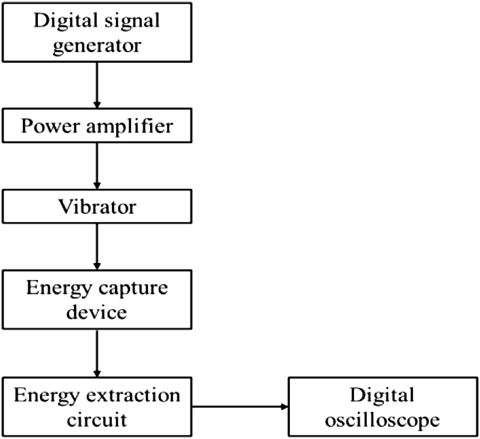
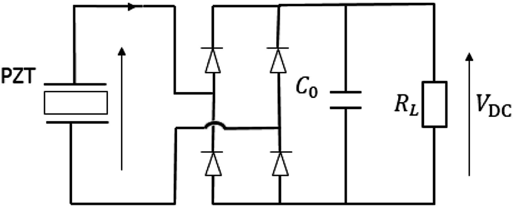
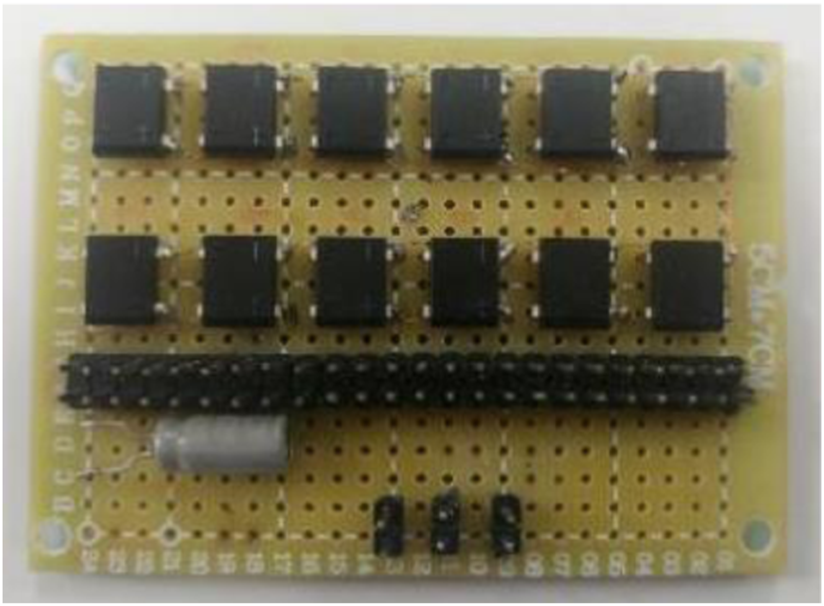
Figure 6 shows the hybrid support beam tested specimens made according to the results of orthogonal optimization, from left to right are single crystal connection, double crystal series, and double crystal parallel piezoelectric beams, respectively. As shown in Figure 7, the piezoelectric beams are mounted on the experimental test rig for voltage and power tests. As shown in Figure 8, the workflow of the experiment is as follows: the digital signal generator generates a sinusoidal excitation signal, which is amplified by the power amplifier and then drives the shaker, the piezoelectric energy harvester converts the vibration energy generated by the shaker into electrical energy. The open-circuit output voltage of the piezoelectric energy harvester is measured directly by a digital oscilloscope. And when measuring the output power, the electrode of the piezoelectric sheet is connected to a standard energy extraction circuit, and the circuit diagram is shown in Figure 9. The alternating current generated by the piezoelectric sheet is rectified and filtered to form a stable voltage output. The output power can be calculated from the voltage and resistance after connecting a load with a specific resistance value. The actual circuit is shown in Figure 10. Tested specimens. Experiment platform. Experimental work flow chart. Circuit diagram. Real circuit figure.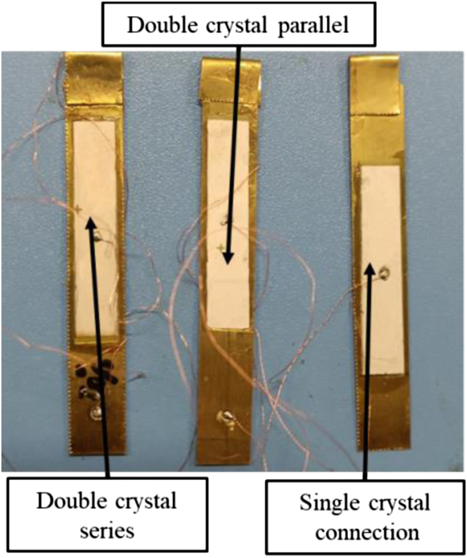
When the value of external excitation acceleration is 1.0 g and the excitation frequency is its natural frequency, the maximum output voltage under different connection modes is shown in Figure 11. As can be seen from the figure, the maximum output voltage of single crystal connection is the same as that of double crystal parallel connection. Double crystal connection means that two piezoelectric plates are pasted on the upper and lower surfaces of the piezoelectric matrix, single crystal means that only one piezoelectric ceramic plate is pasted on the surface of the piezoelectric matrix, while the maximum output voltage of double crystal series connection is twice that of single crystal connection and double crystal parallel connection. The polarization directions of the upper and lower piezoelectric ceramic crystals in parallel and series are all in the 3 direction, that is, the surface of charge generation is perpendicular to the z axis, and the d31 working mode is adopted. The polarization direction of the upper and lower piezoelectric ceramic plates with double crystal parallel is the same, forming potential with the different sign charge on the elastic substrate, respectively, and the thickness of the piezoelectric oscillator is the same, so the output voltage of double crystal parallel and single crystal connection is the same. The polarization directions of the upper and lower piezoelectric ceramic plates in double crystal series are opposite, and positive and negative charges are formed on the surface of the upper and lower piezoelectric ceramic plates. Therefore, the maximum output voltage of the double crystal series is twice that of the single crystal connection. Maximum output voltage under different connection modes.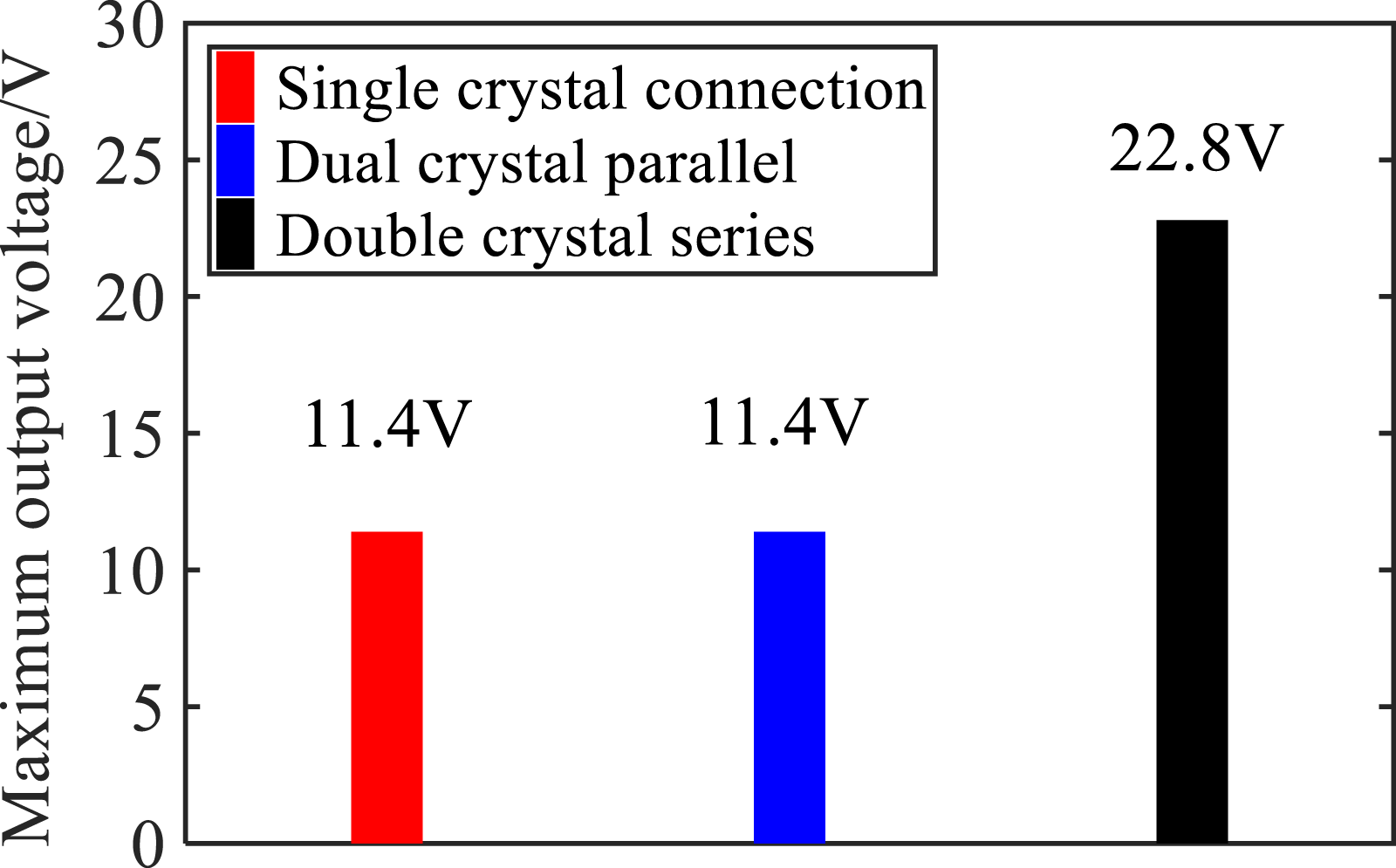
When the external load resistance is 1kΩ and the external excitation acceleration is 1.0 g, and the excitation frequency is its natural frequency, the maximum output power of different connection modes is shown in Figure 12. It can be seen from the figure that, under the same experimental conditions, the maximum output power of the double crystal connection in series is greater than that of the single crystal connection and the double crystal parallel connection. According to the high output voltage and high output power, the connection mode of the upper and lower piezoelectric ceramic plates of the energy harvesting structure is double crystal series. Maximum output power of different connection methods.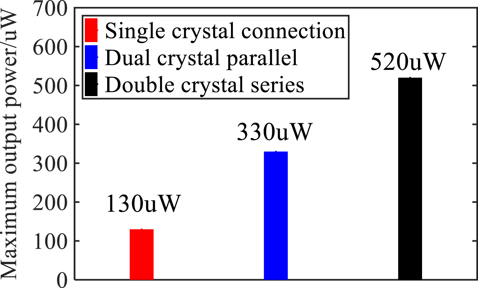
Based on the double crystal series, the sizes of the upper and lower piezoelectric ceramic pieces are exactly the same in the coincidence degree test, and the selected piezoelectric ceramic piece size is 40 mm*8 mm*0.3 mm. In this paper, the ratio of the overlap area of the upper and lower piezoelectric plates to the area of the single piezoelectric plate is defined as the overlap degree, which can be expressed by γ. The value of γ is 0–1. When γ is 0, it means that the projection overlap area of the upper and lower piezoelectric ceramic slices on the horizontal plane is 0, and when γ is 1, it means that the projection overlap of the upper and lower piezoelectric ceramic slices on the horizontal plane is completely. In this paper, voltage and power tests of piezoelectric vibrators with different degrees of coincidence are carried out to explore the optimal degree of coincidence.
When the value of external excitation acceleration is 1.0 g, the first order natural frequency of different coincidence degrees as shown in Figure 13, the figure shows that when the coincidence degree increased from 0 to 1, the first order natural frequency of piezoelectric vibrator first increases then decreases, that is due to the change of coincidence degree can change the stiffness of the piezoelectric vibrator, the change of the stiffness influence the first-order natural frequency of piezoelectric vibrator. Among them, the maximum difference between the first-order natural frequencies with different coincidence degrees is 7 Hz. This indicates that the adjustment of the acquisition band of the energy harvester can be achieved by changing the degree of coincidence, thus enhancing the environmental adaptability of the piezoelectric energy harvester. If multiple arrays of specimens with different coincidence degrees are used, the acquisition band can be further broadened to improve the energy acquisition efficiency. First-order natural frequencies of different coincidence degrees.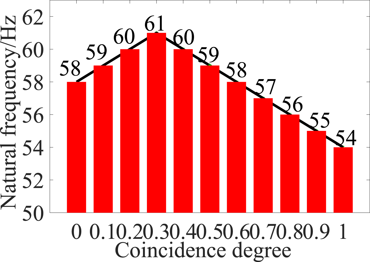
When the value of external excitation acceleration is 1.0 g, the output voltages of different coincidence degrees are shown in Figure 14. As can be seen from the figure, when the coincidence degree increases from 0 to 1, the output voltage of the piezoelectric vibrator first increases and then decreases. As can be seen from Figure 14, the difference in the maximum output voltage for different degrees of the coincidence is 7.02 V. Therefore, changing the coincidence degree can adjust the harvesting output voltage within a certain range. Output voltages with different degrees of coincidence.
When an external load for 1 kΩ and external excitation acceleration of 1.0 g, different coincidence degrees of output power as shown in Figure 15, the figure shows that when the coincidence degree increased from 0 to 1, the output of the piezoelectric vibrator work first increases then decreases, coincidence degree is 0.7 with maximum output power, the maximum is 592 μW, minimizes the output power when the coincidence degree of 0, minimum 297 μW, The maximum difference is 295 μW, because the different coincidence degree will change the axial stress distribution of the piezoelectric vibrator, and the change of stress distribution will affect the utilization rate of the piezoelectric ceramic sheet, and then affect the output power of the piezoelectric vibrator. Output power with different degree of coincidence.
In conclusion, the output voltage and output power of the piezoelectric vibrator are the maximum when the coincidence degree is 0.7. With the large output voltage and the large output power as the optimization objectives, the optimal connection mode is double crystal series, and the optimal coincidence degree is 0.7. Based on this, the output characteristics will be studied.
Different external load power output are shown in Figure 16, the figure shows that when external demand is gradually increasing load, the maximum output of piezoelectric vibrator work first increases then decreases, that external load blindly does not always increase output power, so there is optimal load, it is due to the power relationship between size and resistance relationship of a quadratic function, There is an optimal output power at the optimal load. Output power of different external loads.
Rated power of common low-power sensors.
Test system construction
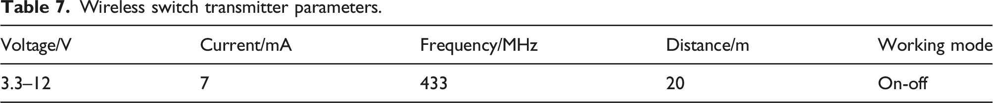
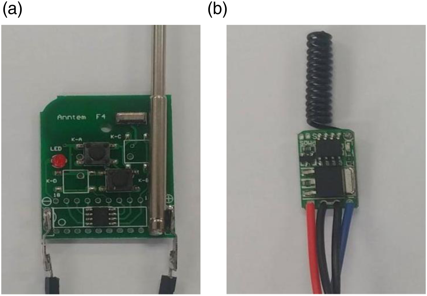
The energy harvesting structure was installed on the experimental platform, and the self-powered wireless switch test system was built. The performance test was carried out under the condition of the external excitation frequency of 50–60 Hz. Among them, the wireless switch power supply test system structure diagram as shown in Figure 17, when the inside of the storage capacitor DC to power a wireless switch transmitter, wireless switch the receiver to receive the launch of the signal transmitter, whether by LED light up successful signal whether receive and display the receiving end since the wireless switch power supply test system can work normally, Table 7 is the working parameters of the transmitting end of the wireless switch, and Figure 18 is the physical diagram of the transmitting end and the receiving end of the wireless switch. Schematic diagram of self-powered wireless switch test system. Wireless switch transmitter parameters. Physical Picture of Wireless Switch: (a) Wireless switch transmitter and (b) Wireless switch receiving end.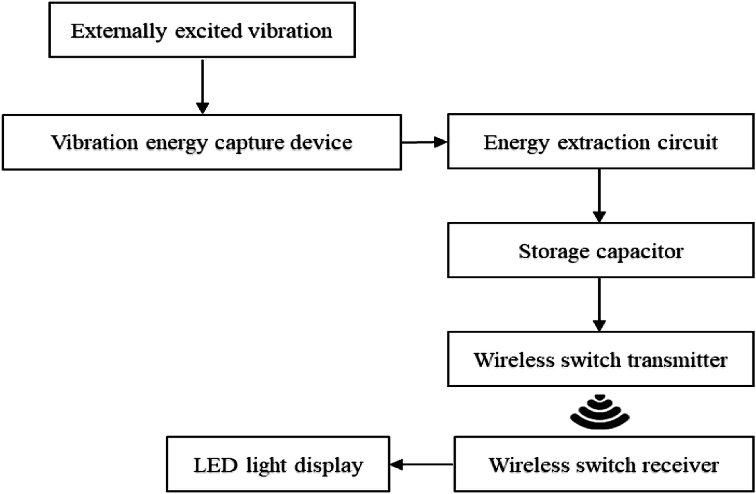
The primary process of the wireless switch power supply experiment is as follows: First, connect the capacitor in the standard energy extraction circuit to the wireless transmitter, and use the vibrator to excite the piezoelectric energy harvester. When the oscilloscope shows that the voltage across the capacitor reaches 3.3 V, press the transmit button at the wireless transmitter, and then the blue indicator at the wireless receiver lights up, as shown in Figure 19, indicating that the wireless receiver has received the signal from the wireless transmitter, which proves that the energy harvester can supply power to the wireless transmitting node or other low-power devices. The above effect can be achieved by repeating the above experimental process for many times, which proves that the output of the capture energy structure is stable and the experimental repeatability is good. Wireless switch self-powered experimental diagram.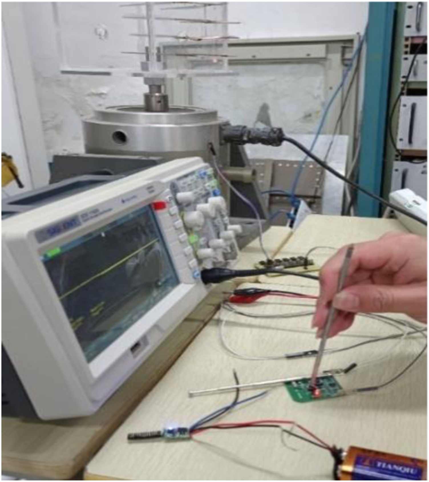
By building a test system, the transmitter of the wireless switch can transmit signals normally, which verifies the feasibility of the asymmetric hybrid beam piezoelectric vibration energy harvesting structure to power the wireless switch. Moreover, the asymmetric hybrid beam piezoelectric vibration energy harvesting structure proposed in this paper has a certain research and application value.
Conclusions
In order to meet the needs of powering low-power wireless switches in low-frequency vibration environments, an asymmetric hybrid supported beam piezoelectric vibration energy harvester is proposed. Firstly, the structure was analyzed theoretically and the optimization parameters were determined. Secondly, the support mode of the structure was optimized, and the size of the piezoelectric ceramic sheet was optimized by orthogonal analysis method. Subsequently, the connection mode and coincidence degree of the upper and lower piezoelectric ceramic sheets were optimized, and the test samples were made to test their power generation performance through experiments. The results show that the asymmetric hybrid supported beam piezoelectric vibration energy harvester has a low effective collection frequency band and good output performance. When the excitation acceleration is 1.0 g and the load is 50 kΩ, the output power of the harvester can reach 770 μW. Finally, by building a wireless switch test platform, it is verified that the energy harvester designed in this paper can supply power to the wireless switch.
Footnotes
Declaration of conflicting interests
The author(s) declared no potential conflicts of interest with respect to the research, authorship, and/or publication of this article.
Funding
This work is supported by The University Natural Science Research Program of Anhui Province (Grant No. KJ2020A0281), Anhui Provincial Natural Science Foundation (Grant No. 2008085ME178), The University Synergy Innovation Program of Anhui Province (Grant No. GXXT-2019-048), The Top Talent Program of Anhui Province (Grant No. gxbjZD202020063), The Key Research and Development Program of Anhui Province (Grant No. 202104a07020005), and Supported by the State Key Laboratory of Science and Technology of China (Grant No. SKLMRDPC20ZZ01).